1
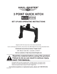
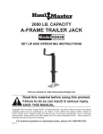
120w fountain pump
66514
Set up, Operating and maintenance
Instructions
Distributed exclusively by Harbor Freight Tools®.
3491 Mission Oaks Blvd., Camarillo, CA 93011
Visit our website at: http://www.harborfreight.com
Read this material before using this product.
Failure to do so can result in serious injury.
Save this manual.
Copyright© 2008 by Harbor Freight Tools®. All rights reserved. No portion of this manual or any artwork
contained herein may be reproduced in any shape or form without the express written consent of
Harbor Freight Tools. Diagrams within this manual may not be drawn proportionally. Due to continuing
improvements, actual product may differ slightly from the product described herein. Tools required for
assembly and service may not be included.
For technical questions or replacement parts, please call 1-800-444-3353.
of California to cause cancer, and
birth defects or other reproductive
harm. Wash hands after handling.
(California Health & Safety Code §
25249.5, et seq.)
CAUTION
This pump has been evaluated for
use with water only.
WARNING
Important! For your own safety –
before starting to run the pump, please
have the following items checked by an
expert:
1.
Risk of electric shock – This pump is
supplied with a grounding conductor
and grounding-type attachment plug.
To reduce the risk of electric shock,
connect only to a properly grounded,
grounding-type receptacle.
2.
Risk of electric shock – This pump
has not been investigated for use in
swimming pool areas.
3.
The electrical connections must be
protected from moisture.
4.
If there is danger of flooding, the
electrical connections must be taken
to higher ground.
5.
Circulation of caustic or explosive
fluids, as well as the circulation of
abrasive materials, must be avoided
at all costs.
6.
The pump must be protected from
frost.
7.
The pump must be protected from
running dry.
8.
Access by children should also be
prevented with appropriate measures.
9.
WARNING: Handling the Power Cord
on this product will expose you to
lead, a chemical known to the State
SKU 66514
10. The warnings, precautions, and instructions discussed in this instruction
manual cannot cover all possible conditions and situations that may occur.
It must be understood by the operator
that common sense and caution are
factors which cannot be built into this
product, but must be supplied by the
operator.
Fluid Type
The Pump is designed for use with
water with a maximum temperature of 77°
F (25°C). Do not use the pump for other
fluids, especially not fuels, cleaning fluids,
or other chemical products.
Specifications
Flow
15.4 GPM
Maximum Height
8 ft.
Electrical Requirements
120 V~, 60 Hz
E197437
For technical questions, please call 1-800-444-3353.
Page 2
Unpacking
When unpacking, check to make sure
that the item is intact and undamaged. If
any parts are missing or broken, please
call Harbor Freight Tools at the number
shown on the cover of this manual as soon
as possible.
Installation
Read the entire Important
Safety Instructions
section at the beginning of this
manual including all text under
subheadings therein before set
up or use of this product.
To prevent
serious injury
from accidental
operation:
Unplug the Fountain Pump
from its electrical outlet
before assembling,
inspecting, making any
adjustments, or servicing.
Note: For additional information regarding
the parts listed in the following pages,
refer to the Assembly Diagram near
the end of this manual.
SKU 66514
Figure 1
Spray Nozzle (9)
Output Tube (7)
Tee Fitting System
(10)
Coupling
Nut (5)
Main Housing (4)
1.
Thread the Coupling Nut (5) to the
Main Housing (4).
2.
Thread the Tee Fitting System (10) to
the top of the Coupling Nut (5).
NOTE: There are two ON/OFF Switches
on the Tee Fitting System (10).
Turning either Switch 90° changes
it from OFF to ON, or ON to OFF.
(Stamped onto the Fountain Pump
parts are PLUS/MINUS symbols
showing either open, or closed.)
See Figure 2.
Figure 2
3.
Thread the Output Tube (7) to the top
of the Tee Fitting System (10).
4.
Thread the Bell Nozzle (8), the Bubbling Nozzle (6), or the Spray Nozzle
For technical questions, please call 1-800-444-3353.
Page 3
(9) to the top of the Output Tube (7)
depending on what type of water display you desire. See Figure 1.
5.
The Spray Nozzle (9) is threaded to
the top of the Output Tube (7) when
needed.
Available Accessories/
Attachments
This Fountain Pump comes with
three separate heads for different
types of water spray:
3.
When the plug is inserted into the
receptacle the pump will be on.
WARNING! If the power cord or plug is
damaged, do not use the pump. The
power cord or plug may only be repaired by a certified electrician.
Area of use
This pump is designed for use as a
fountain pump in an area not used for
swimming.
a.Bubbling Nozzle (6) features tiny
holes that disperse water in all directions at once.
b.Bell Nozzle (8) will shoot water
straight up to a maximum height of
8 ft.
c. Spray Nozzle (9) shoots many small
streams of water in a tight pattern.
d.All three spray heads thread onto
and off of the top of the Output tube
(7) for quick interchanging.
WARNING! Always unplug the Fountain
from the power outlet and put on a
pair of heavy-duty, insulated rubber gloves, before sticking hands
in water to change spray heads or
any other handling of the Fountain
Pump.
Power Supply
1.
The pump is equipped with a grounded plug according to regulations. The
pump is designed to be connected to
120 V~, 60 Hz receptacle.
2.
Make sure that the receptacle is sufficiently secured and is in excellent
condition.
SKU 66514
For technical questions, please call 1-800-444-3353.
Page 4
Operating Instructions
Maintenance And
Servicing
Read the entire Important
Safety Information section
at the beginning of this manual
including all text under
subheadings therein before set
up or use of this product.
1.
Procedures not specifically
explained in this manual
must be performed only by a
qualified technician.
To prevent
serious injury
from accidental
operation or electric
shock:
Unplug the Fountain Pump
from its electrical outlet
before performing any
accessory change, inspection,
maintenance, and/or cleaning
procedures.
After reading these instructions,
consider the following points before
starting the pump:
a.Verify that the pump rests on the
floor of the fountain.
b.Verify that the electrical connection
is 120 V~, 60 Hz.
c. Verify that the electrical receptacle is
in good condition.
d.Verify that water and moisture cannot get near the power supply receptacle.
To prevent serious
injury from tool
failure:
Do not use damaged
equipment. If abnormal noise
or vibration occurs, have the
problem corrected before
further use.
e.Verify that the pump is installed so
as to prevent running dry.
2.
To prevent tripping, run any extension
cord used away from walkways that
lead to your location.
4.
Place the Fountain Pump on a surface slightly elevated (to prevent collection of excessive mud), and open
either or both switches located on the
Tee Fitting System (10) by rotating
them towards the + symbol.
5.
Plug the Fountain Pump into the
power outlet. The Fountain Pump will
begin operating automatically.
6.
When not using the Fountain Pump
for a long period of time, unplug the
power cord, remove it from the water,
rinse with cold, clean, water and let it
dry before storing it inside away from
children.
SKU 66514
Cleaning, Maintenance, and
Lubrication
1.
BEFORE EACH USE, inspect the
general condition of the Fountain
Pump. Check for loose screws, misalignment or binding of moving parts,
cracked or broken parts, damaged
electrical wiring, and any other condition that may affect its safe operation.
2.
After Use, clean external surfaces
of the appliance with clean, moist
cloth.
For technical questions, please call 1-800-444-3353.
Page 5
WARNING! If the supply cord of this appliance is damaged, it must be replaced
only by a qualified service technician.
Figure 3
Back Cover (3)
Cleaning the Filter Sponge
1.
Wash the Filter Sponge out regularly, especially if the Fountain Pump
power starts to drop.
2.
Unplug the Fountain Pump from the
power source and wear heavy-duty
insulated rubber gloves before putting
your hands into the water.
3.
Press the sides of the Filter Cover
(14) together and pull it off the Main
Housing (4). Pull the Filter Sponge
out of the Plastic Filter (13) and rinse
with cold, clean water. Replace into
the Plastic Filter (13) and reassemble
the Filter Cover (14).
4.
When not using the Fountain Pump,
(as in the Winter months), protect and
preserve the Filter Sponge by keeping it in a glass jar in water stored
near the Fountain Pump for easy
location.
Impeller (11)
Metal Washer
3.
Replace the Impeller (11) as in number 1 of this section using reverse
procedure. Check for Metal Washer
before replacing the Back Cover (3).
Cleaning the Impeller
1.
Unscrew the Back Cover (3), (twist it
1/4 turn to left and pull). Remove the
Impeller (11). See Figure 3.
NOTE: There is a small Metal Washer
attached to the rear of the Impeller Shaft. Be careful not to lose
it when removing, cleaning, and
replacing the Impeller.
2.
Flush with lots of lukewarm, clean
water to remove built up debris. Use
of a small medium stiff toothbrush is
helpful.
SKU 66514
For technical questions, please call 1-800-444-3353.
Page 6
Troubleshooting
Problem
Possible Causes
Fountain Pump will not 1. No power at outlet.
start
2. Circuit breaker tripped.
3. Cord not connected.
Low flow from
1. Possible clogging of Filter Sponge.
Nozzle(s)
2. Possible excess debris lodged in
Impeller.
3. Possibly the two Switches located
on the Tee Fitting System are only
partially ON.
Likely Solutions
1. Check power at outlet.
2. Check circuit breaker for outlet.
3. Check that cord is plugged in.
1. Check and clean the Filter Sponge
per instructions in Maintenance
Section on Page 8.
2. Check and clean debris from
Impeller per instructions on Page 8.
3. Check both Switches. Turn both
fully towards the symbol of the open
bicycle lock.
Follow all safety precautions whenever diagnosing or servicing the
appliance. Disconnect power supply before service.
PLEASE READ THE FOLLOWING CAREFULLY
The manufacturer and/or distributor has provided the parts list and assembly
diagram in this manual as a reference tool only. Neither the manufacturer or
distributor makes any representation or warranty of any kind to the buyer that
he or she is qualified to make any repairs to the product, or that he or she is
qualified to replace any parts of the product. In fact, the manufacturer and/
or distributor expressly states that all repairs and parts replacements should
be undertaken by certified and licensed technicians, and not by the buyer. The
buyer assumes all risk and liability arising out of his or her repairs to the
original product or replacement parts thereto, or arising out of his or her
installation of replacement parts thereto.
PARTS LIST and Assembly Diagram
Part
1
3
4
5
6
7
8
9
10
11
12
13
14
Description
Power Plug
Back Cover
Main Housing
Coupling Nut
Bubbling Nozzle
Output Tube
Bell Nozzle
Spray Nozzle
Tee Fitting System
Impeller
Filter Body
Plastic Filter
Filter Cover
SKU 66514
Q’ty
1
1
1
1
1
1
1
1
1
1
1
1
1
For technical questions, please call 1-800-444-3353.
Page 7
Record Product’s Serial Number Here:
Note: If product has no serial number, record month and year of purchase instead.
Note: Some parts are listed and shown for illustration purposes only, and are not available individually as replacement parts.
Limited 1 year / 90 Day warranty
Harbor Freight Tools Co. makes every effort to assure that its products meet high
quality and durability standards, and warrants to the original purchaser that for a period
of ninety days from date of purchase that the engine/motor, the belts (if so equipped),
and the blades (if so equipped) are free of defects in materials and workmanship. Harbor Freight Tools also warrants to the original purchaser, for a period of one year from
date of purchase, that all other parts and components of the product are free from
defects in materials and workmanship (90 days if used by a professional contractor or
if used as rental equipment). This warranty does not apply to damage due directly or
indirectly, to misuse, abuse, negligence or accidents, repairs or alterations outside our
facilities, normal wear and tear, or to lack of maintenance. We shall in no event be liable
for death, injuries to persons or property, or for incidental, contingent, special or consequential damages arising from the use of our product. Some states do not allow the
exclusion or limitation of incidental or consequential damages, so the above limitation
of exclusion may not apply to you. This warranty is expressly in lieu of all
other warranties, express or implied, including the warranties of
merchantability and fitness.
To take advantage of this warranty, the product or part must be returned to us with
transportation charges prepaid. Proof of purchase date and an explanation of the complaint must accompany the merchandise. If our inspection verifies the defect, we will either repair or replace the product at our election or we may elect to refund the purchase
price if we cannot readily and quickly provide you with a replacement. We will return repaired products at our expense, but if we determine there is no defect, or that the defect
resulted from causes not within the scope of our warranty, then you must bear the cost
of returning the product.
This warranty gives you specific legal rights and you may also have other rights
which vary from state to state.
3491 Mission Oaks Blvd. • PO Box 6009 • Camarillo, CA 93011 • (800) 444-3353
SKU 66514
For technical questions, please call 1-800-444-3353.
Page 8