1
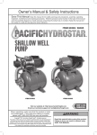
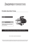
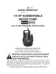
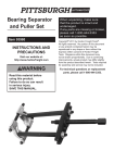
Owner’s Manual & Safety Instructions
Save This Manual Keep this manual for the safety warnings and precautions, assembly, operating,
inspection, maintenance and cleaning procedures. Write the product’s serial number in the back of the manual
near the assembly diagram (or month and year of purchase if product has no number). Keep this manual and
the receipt in a safe and dry place for future reference.
ITEM 69297
CLEAR WATER
PUMP
Visit our website at: http://www.harborfreight.com
Email our technical support at: [email protected]
When unpacking, make sure that the product is intact
and undamaged. If any parts are missing or broken,
please call 1-800-444-3353 as soon as possible.
Copyright© 2011 by Harbor Freight Tools®. All rights reserved.
No portion of this manual or any artwork contained herein may be reproduced in
any shape or form without the express written consent of Harbor Freight Tools.
Diagrams within this manual may not be drawn proportionally. Due to continuing
improvements, actual product may differ slightly from the product described herein.
Tools required for assembly and service may not be included.
Read this material before using this product.
Failure to do so can result in serious injury.
Save this manual.
WARNING
When using electric pumps, basic safety
precautions should always be followed to reduce the
risk of fire, electric shock, and personal injury. Read
all instructions before using this pump!
1. This Pump has not been investigated for
use in swimming pool or marine areas.
2. Use only with clear water. Do not use
with flammable liquids such as gasoline,
chemicals or and corrosive liquids.
3. Do not use extension cords with this Pump.
4. Risk of electric shock – This pump is supplied
with a grounding conductor and grounding‑type
attachment plug. To reduce the risk of
electric shock, connect only to a properly
grounded, grounding-type receptacle.
5. If there is danger of flooding, the electrical
connections must be taken to higher ground.
11. REPLACEMENT PARTS AND ACCESSORIES.
When servicing, use only identical replacement
parts. Use of any other parts will void the
warranty. Only use accessories intended for
use with this pump. Approved accessories
are available from Harbor Freight Tools.
12. The pump must be protected from frost.
13. The pump must be protected from running dry.
14. Do not run the pump with the outlet
closed or blocked. The connections may
burst due to excessive pressure.
15. WARNING: Handling the cord on this product will
expose you to lead, a chemical known to the State
of California to cause cancer, and birth defects or
other reproductive harm. Wash hands after handling.
(California Health & Safety Code § 25249.5, et seq.)
6. DO NOT IMMERSE IN WATER. This is not
a submersible pump. Use indoors only.
7. Always lock up pumps and keep
out of reach of children.
8. Wear ANSI-approved safety
goggles during installation.
9. DISCONNECT POWER. Unplug when not in use,
before servicing, and when changing accessories.
10. CHECK DAMAGED PARTS. Before using any
pump, check for alignment and binding of moving
parts; any broken parts or mounting fixtures; and
any other condition that may affect proper operation.
Any part that is damaged should be properly
repaired or replaced by a qualified technician.
Page 2
For technical questions, please call 1-800-444-3353.
SKU 69297
Grounding Instructions
To prevent electric shock and death from incorrect grounding wire connection
Read and follow these instructions:
Check with a qualified electrician if you
2. The grounding prong in the plug is connected through
are in doubt as to whether the outlet is
the green wire inside the cord to the grounding
properly grounded. Do not modify the
system in the tool. The green wire in the cord must
power cord plug provided with the tool.
be the only wire connected to the tool’s grounding
Never remove the grounding prong from the plug. Do
system and must never be attached to an electrically
not use the tool if the power cord or plug is damaged.
“live” terminal. (See 3-Prong Plug and Outlet.)
If damaged, have it repaired by a service facility
3. The tool must be plugged into an appropriate outlet,
before use. If the plug will not fit the outlet, have a
properly installed and grounded in accordance with
proper outlet installed by a qualified electrician.
all codes and ordinances. The plug and outlet should
look like those in the preceding illustration.
(See 3-Prong Plug and Outlet.)
4. This pump is intended for use on a circuit that has
an outlet that looks like the one illustrated above in
125 V~ 3-Prong Plug and Outlet. The pump has
a grounding plug that looks like the plug illustrated
above in 125 V~ 3-Prong Plug and Outlet.
Grounding
Pin
125 V~ 3-Prong Plug and Outlet
(for up to 125 V~ and up to 15 A)
1. Tools marked with “Grounding Required” have a three
wire cord and three prong grounding plug. The plug
must be connected to a properly grounded outlet.
If the tool should electrically malfunction or break
down, grounding provides a low resistance path to
carry electricity away from the user, reducing the risk
of electric shock. (See 3-Prong Plug and Outlet.)
5. The outlet must be properly installed and grounded
in accordance with all codes and ordinances.
6. Do not use extension cords with this pump.
7. Do not use an adapter to connect
this pump to a different outlet.
Symbology
Double Insulated
Read the manual before
set-up and/or use.
Canadian Standards Association
WARNING marking
concerning Risk of Fire.
Do not cover ventilation ducts.
Keep flammable objects away.
WARNING marking concerning
Risk of Electric Shock.
Properly connect power cord
to appropriate outlet.
WARNING marking concerning
Risk of Explosion.
Do not use to pump
explosive materials.
Underwriters Laboratories, Inc.
V~
A
Volts Alternating Current
Amperes
n0 xxxx/min. No Load Revolutions per Minute (RPM)
WARNING marking concerning Risk
of Eye Injury. Wear ANSI‑approved
safety goggles with side shields.
SKU 69297
For technical questions, please call 1-800-444-3353.
Page 3
Specifications
Power Requirements
Discharge/Intake
Maximum Flow
Maximum Delivery Height
Suction Lift
Pressure
Cord Length
120V~ 60Hz 5A
1 IN. NPT
650 GPH
98 FT.
20 FT.
43 PSI
6 FT.
Set up
To prevent electric shock and death from incorrect usage follow
these instructions:
This is NOT a submersible pump.
Do not immerse in water.
Pipe Connection
The Pump uses 1" NPT piping (sold separately).
Purchase the necessary length of pipe, including any
needed fittings and bends. Mount the Pump as close to
the source of water as possible and within the range of
the rated Suction Lift. The connections must be airtight.
Wrap all threaded connections with PTFE tape (sold
separately).
Priming Plug Outlet
1. Remove the Inlet and Outlet Covers from the Pump.
2. Attach the water source to the Inlet, using appropriate
methods. The Inlet hose or pipe must be collapseproof to properly withstand the suction force.
3. Install a foot valve (sold separately)
at the bottom of the inlet.
4. Attach the outlet connection to the Outlet. A
Y-fitting with dual valves (sold separately) is
helpful for priming the pump (see next section).
Inlet
Figure 1
Page 4
Pump
Housing
For technical questions, please call 1-800-444-3353.
SKU 69297
Operation
To prevent electric shock and death:
Make sure that the Motor Cover is properly closed and sealed before priming or operation.
Note:
A foot valve on the inlet connection is critical to help prevent the pump from losing prime.
Note: Check that the water source and piping are clear of sand, dirt and debris.
2. Close the valve on the outlet side of the Y-fitting, and
open the valve on the priming side of the Y-fitting.
3. Remove the Priming Plug and wait until water
starts coming out of the Priming Plug. Replace
the Priming Plug and tighten securely.
Bucket
full of
clean
water
4. To start the pump:
Pr
im
Y-fitting
a. Open the valve on the outlet side of the Y-fitting.
in
g
Ho
se
Outlet Pipe
b. Make sure your hands are dry.
c. Plug in the pump.
d. Close the valve on the priming side of the Y-fitting.
(with one valve
for each outlet)
Inlet Pipe
Pump
Foot
Valve
1. Connect a bucket full of at least 3 gallons of water
to one side of the Y-fitting using a hose, as shown
above. (If available, a continuous water supply,
such as a spigot, may be used instead.) The bucket
must be positioned higher than the pump’s outlet.
CAUTION: Do not run the Pump Dry!
Turn off the Pump immediately if water
stops coming out the Outlet.
5. If you operate the Pump and no water comes
out, shut the Pump off IMMEDIATELY. Check the
pipes for air-tightness. Check also that the bottom
of the Inlet pipe is underneath the surface of the
water and a foot valve is properly installed.
6. After the pump is running properly, the priming
hose and bucket can be disconnected.
Storage
1. If you will not be using the Pump for an
extended period of time, drain the Pump
Housing. First disconnect both the suction
and outlet lines, then tip the pump so that all
the water is drained from the pump cavity.
2. If the Pump sits idle for a period of 5 days
or more, it should be unplugged and rotated
with a screwdriver through the middle hole of
the fan cover through several revolutions to
prevent it from taking a permanent set.
3. If you use the Pump only occasionally, when
you are done pumping, replace the Inlet
and Outlet Covers to protect the unit.
SKU 69297
For technical questions, please call 1-800-444-3353.
Page 5
Troubleshooting
Problem
Motor will
not start.
Possible Causes
1. Cord not connected.
2. No power at outlet.
3. Fuse is blown or breaker tripped.
Motor runs
but water isn’t
pumping.
Pump does not
deliver water at
full capacity.
Excessive noise
or rattling.
4. Internal damage or wear. (Carbon
brushes or switch, for example.)
1. Improper priming.
2. Clogged filter at end of
intake connections.
3. Discharge valve closed.
4. Pipe size too small.
Likely Solutions
1. Check that cord is plugged in.
2. Check power at outlet. If outlet is unpowered,
turn off tool and check circuit breaker. If breaker
is tripped, make sure circuit is right capacity
for tool and circuit has no other loads.
3. Turn off and unplug pump, have fuse replaced
by a qualified service technician.
4. Have serviced by a qualified service technician.
1. Re-prime according to directions.
2. Clean filter.
3. Open discharge valve.
4. Re-pipe using pipe of the same size as
the Pump inlet and outlet ports.
5. Impeller plugged.
5. Have Impeller cleaned by qualified service technician.
6. Pipes frozen.
6. Thaw pipes. Check for damage before using pump.
1. Corroded pipes.
1. Replace pipes.
2. Piping size too small.
2. Re-pipe using pipe of the same size as
the Pump inlet and outlet ports.
3. Not enough water supplied to Pump. 3. Enlarge inlet pipe. Check well pump system.
4. Low Voltage.
4. Check that outlet is 120V.
Internal damage or wear. (Carbon
Have technician service tool.
brushes or bearings, for example.)
Follow all safety precautions whenever diagnosing or servicing the tool. Disconnect power
supply before service.
PLEASE READ THE FOLLOWING CAREFULLY
THE MANUFACTURER AND/OR DISTRIBUTOR HAS PROVIDED THE PARTS DIAGRAM IN THIS MANUAL AS A
REFERENCE TOOL ONLY. NEITHER THE MANUFACTURER NOR DISTRIBUTOR MAKES ANY REPRESENTATION OR WARRANTY OF ANY KIND TO THE BUYER THAT HE OR SHE IS QUALIFIED TO MAKE ANY REPAIRS
TO THE PRODUCT OR THAT HE OR SHE IS QUALIFIED TO REPLACE ANY PARTS OF THE PRODUCT. IN
FACT, THE MANUFACTURER AND/OR DISTRIBUTOR EXPRESSLY STATES That ALL REPAIRS AND PARTS
REPLACEMENTS SHOULD BE UNDERTAKEN BY CERTIFIED AND LICENSED TECHNICIANS AND NOT BY THE
BUYER. THE BUYER ASSUMES ALL RISK AND LIABILITY ARISING OUT OF HIS OR HER REPAIRS TO THE
ORIGINAL PRODUCT OR REPLACEMENT PARTS THERETO, OR ARISING OUT OF HIS OR HER INSTALLATION
OF REPLACEMENT PARTS THERETO.
Page 6
For technical questions, please call 1-800-444-3353.
SKU 69297
Parts list and Diagram
Item
1
2
3
4
5
6
7
8
9
10
11
12
13
14
15
16
17
Description
Bolt
Pump Housing
Priming Plug
O-Ring
Impeller
C-clip
Washer
Mechanical Seal
Bolt
O-Ring
Seal
Frame
Ball Bearing
Key
Rotor
Ball Bearing
Wave Spring
Qty
3
1
1
1
1
2
1
1
3
1
1
1
1
1
1
1
1
Item
18
19
20
21
22
23
24
25
26
27
28
29
30
31
32
33
34
Description
Capacitor Box
Terminal Board
Motor Housing
Cable Holder
End Plate
Hex Bolt
Fan
Fan Cover
Screw
Capacitor
Screw
Cord Clip
Screw
Spring Washer
Washer
Power Cord
Cover
Qty
1
1
1
1
1
3
1
1
2
1
2
1
1
1
1
1
2
Record Product’s Serial Number Here:
Note: If product has no serial number, record month and year of purchase instead.
Note: Some parts are listed and shown for illustration purposes only,
and are not available individually as replacement parts.
SKU 69297
For technical questions, please call 1-800-444-3353.
Page 7
Limited 90 Day Warranty
Harbor Freight Tools Co. makes every effort to assure that its products meet high quality and durability
standards, and warrants to the original purchaser that this product is free from defects in materials and workmanship
for the period of 90 days from the date of purchase. This warranty does not apply to damage due directly or
indirectly, to misuse, abuse, negligence or accidents, repairs or alterations outside our facilities, criminal activity,
improper installation, normal wear and tear, or to lack of maintenance. We shall in no event be liable for death,
injuries to persons or property, or for incidental, contingent, special or consequential damages arising from the use
of our product. Some states do not allow the exclusion or limitation of incidental or consequential damages, so the
above limitation of exclusion may not apply to you. This warranty is expressly in lieu of all other
warranties, express or implied, including the warranties of merchantability and fitness.
To take advantage of this warranty, the product or part must be returned to us with transportation charges
prepaid. Proof of purchase date and an explanation of the complaint must accompany the merchandise.
If our inspection verifies the defect, we will either repair or replace the product at our election or we may
elect to refund the purchase price if we cannot readily and quickly provide you with a replacement. We will
return repaired products at our expense, but if we determine there is no defect, or that the defect resulted
from causes not within the scope of our warranty, then you must bear the cost of returning the product.
This warranty gives you specific legal rights and you may also have other rights which vary from state to state.
3491 Mission Oaks Blvd. • PO Box 6009 • Camarillo, CA 93011 • (800) 444-3353
3491 Mission Oaks Blvd. • PO Box 6009 • Camarillo, CA 93011 • (800) 444-3353
Page 8
For technical questions, please call 1-800-444-3353.
SKU 69297