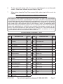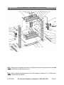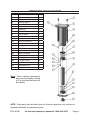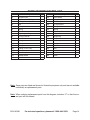
1
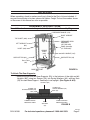
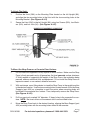
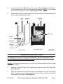
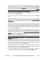
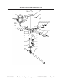
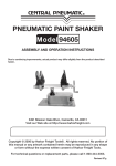
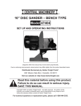
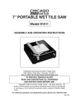
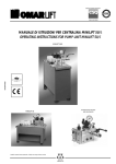
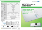
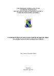
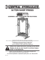
50 TON SHOP PRESS
Model 96188
ASSEMBLY AND OPERATION INSTRUCTIONS
Diagrams within this manual may not be drawn proportionally.
Due to continuing improvements, actual product may differ slightly from the product described herein.
Distributed exclusively by Harbor Freight Tools®.
3491 Mission Oaks Blvd., Camarillo, CA 93011
Visit our website at: http://www.harborfreight.com
Read this material before using this product.
Failure to do so can result in serious injury.
Save this manual.
Copyright© 2007 by Harbor Freight Tools®. All rights reserved. No portion of this
manual or any artwork contained herein may be reproduced in any shape or form
without the express written consent of Harbor Freight Tools.
For technical questions or replacement parts, please call 1-800-444-3353.
REV 11h
Specifications
Maximum Capacity
50 Tons
Compressed Air PSI Range
70 to 150 PSI
Overall Dimensions
67-1/2” H x 56-1/2” W x 31-1/2” D
Rail Width
9-1/4”
Pressure Gauge Markings
0-70 Tons
Pressure Gauge Thread
1/2” NPT
Piston Rod Diameter
2-1/4”
Piston Rod Travel
6-5/8”
Air Inlet Connector Size
1/4” - 18 NPT
Mounting Holes
4 at 3/4” Diameter
Weight
645 Pounds
SAVE THIS MANUAL
You will need this manual for the safety warnings and precautions, assembly,
operating, inspection, maintenance, and cleaning procedures. Keep your invoice
with this manual. Write the invoice number on the inside of the front cover. Keep
this manual and invoice in a safe and dry place for future reference.
GENERAL SAFETY WARNINGS
1.
Keep work area clean and dry. Cluttered, dark or wet work areas invite injuries.
2.
Keep children and bystanders away from work area. Do not allow children or
untrained individuals to handle this product.
3.
Store idle equipment. When not in use, tools and equipment should be stored in
a dry location to inhibit rust. Always lock up tools and equipment and keep out of
reach of children.
4.
Do not use a power tool while tired or under the influence of drugs, alcohol,
or medication. A moment of inattention while operating power tools may result in
serious personal injury. Read warning labels on prescriptions to determine if your
judgment or reflexes are impaired while taking drugs. If there is any doubt, do not
use this product.
5.
Dress with safety in mind. Wear ANSI approved safety impact eyeglasses and
heavy-duty work gloves when using this product. Non-skid footwear or safety shoes
should be used when working with this product. Do not wear loose clothing or jewelry as they can become caught in moving parts. Wear a protective hair covering
to prevent long hair from becoming caught in moving parts.
6.
Industrial applications must follow OSHA requirements.
REV 07j
SKU 96188
For technical questions, please call 1-800-444-3353.
Page 2
7.
Do not overreach. Keep proper footing and balance at all times. Proper footing
and balance enable better control in unexpected situations.
8.
Stay alert. Watch what you are doing at all times. Use common sense. Do not
use this product when you are tired or distracted from the job at hand.
9.
Check for misalignment or binding of moving parts, breakage of parts, and any
other condition that may affect the tool’s operation. If damaged, have the tool
serviced before using. Many accidents are caused by poorly maintained tools.
10.
Maintain this product with care. Keep this tool clean and dry for better and safer
performance.
11.
Maintenance: For your safety, service and maintenance should be performed
regularly by a qualified technician.
12.
Do not force the tool. Use the correct tool for your application. The correct tool
will do the job better and safer at the rate for which it is designed. Do not force the
tool and do not use the tool for a purpose for which it is not intended.
SPECIFIC PRODUCT WARNINGS
1.
Warning: if you detect anything that may indicate imminent structural failure
to the Shop Press, discontinue use immediately. Disconnect the Shop Press
from its compressed air supply source and have the problem corrected before further use.
2.
Do not install this equipment on any asphalt or wood surface. Make sure the
Shop Press is firmly secured to a dry, oil/grease free, flat, level concrete surface
capable of supporting the combined weight of the Shop Press, the workpiece being
pressed, and any additional tools and equipment. Do not install the Shop Press on
expansion seams or on cracked, defective concrete.
3.
Maintain a safe work environment. Do not use the Shop Press near wet areas. Do
not expose this tool to rain. Make sure there is adequate surrounding work space.
Use this tool in a well-ventilated area. Do not operate this tool in the presence of
flammable liquids, gases, or dust.
4.
Read and understand all instructions and safety precautions in the manufacturer’s manual for the workpiece you are pressing. Always use the manufacturer’s
recommended pressing points, minimum/maximum pressing force required, etc. for
the workpiece you are pressing.
5.
Never exceed the maximum PSI and pressing capacity. This Shop Press will do
the work better and safer at the speed and capacity for which it is designed. Do not
exceed the maximum 150 psi compressed air supply or the 50 ton press capacity.
SKU 96188
For technical questions, please call 1-800-444-3353.
Page 3
6.
Remove adjusting keys or wrenches before turning the Shop Press on. A
wrench or a key that is left attached to a rotating part of the power tool may result
in personal injury.
7.
Avoid unintentional starting. Make sure you are prepared to begin work before
squeezing the handle on the Air Valve (40A).
8.
Avoid off-center loads. If the Pressure Head Assembly (22A) seems unusually
hard to press, immediately stop the operation. Disconnect the Shop Press from its
compressed air supply source, and adjust the workpiece to eliminate or diminish
an off-center load. Do not operate the Shop Press if the workpiece tilts or binds
during the down movement of the Pressure Head Assembly.
9.
Prior to lowering the Pressure Head Assembly (22A) remove tool trays, stands,
and all other tools and equipment from the Press Table (6A).
10.
Always keep hands, fingers, and feet away from the Pressure Head Assembly
(22A) and Press Table (6A) during the pressing process.
11.
Never attempt to remove a workpiece stuck in the moving parts of the Shop
Press while it is connected to the compressed air supply source.
12.
The workpiece must be supported and controlled at all times during operation. Use a roller stand (not provided) with a larger workpiece. Whenever possible,
secure the workpiece with clamps (not provided).
13.
Once contact between the pressure head and workpiece has been made,
step away as far as possible and continue to slowly apply pressure until the
procedure is complete.
14.
Never leave a compressed workpiece unattended. When a workpiece is compressed, there is a large degree of force that has been stored in the workpiece, this
must be controlled until the Pressure Head Assembly is released.
15.
Keep the Shop Press properly filled with hydraulic oil. For instructions, see
“Inspection, Maintenance, and Cleaning” section in this manual.
16.
Before performing service or maintenance release the load from the Shop
Press and disconnect it from the compressed air supply source.
17.
WARNING: This product contains or, when used, produces a chemical known
to the State of California to cause cancer and birth defects or other reproductive harm. (California Health & Safety Code § 25249.5, et seq.)
Warning: The warnings, cautions, and instructions discussed in this instruction manual cannot cover all possible conditions and situations that may occur. It
must be understood by the operator that common sense and caution are factors
which cannot be built into this product, but must be supplied by the operator.
SKU 96188
For technical questions, please call 1-800-444-3353.
Page 4
UNPACKING
When unpacking, check to make sure all parts listed in the Parts List are included. If
any parts are missing or broken, please call Harbor Freight Tools at the number shown
on the cover of this manual as soon as possible.
ASSEMBLY INSTRUCTIONS
For additional references to the parts listed below, refer to Assembly Diagrams.
PRESSURE GAUGE (17A)
RIGHT UPRIGHT
(8A)
TOP SHAFT (30A)
PRESSURE HEAD
ASSEMBLY
(1B THRU 22B)
PUMP Assembly.
(1C THRU 35C)
LEFT UPRIGHT
(8A)
HOIST (29A)
ARBOR
PLATE
(23A)
SUPPORT PIN (9A)
JACK HANDLE (19C)
SUPPORT PIN (9A)
Press Table
(6A)
FIGURE A
BASE SUPPORT
(5A)
To Attach The Base Supports:
• Secure the right and left Base Supports (5A) to the bottoms of the right and left
Uprights (8A), using two Screws (2A), two Spring Washers (4A), and two Nuts
(3A) for each Base Support. Seek help to set upright. (See Figure A & B)
UPRIGHT (8A)
SCREW (2A)
SPRING WASHER (4A)
NUT (3A)
SCREW (2A)
SPRING WASHER (4A)
NUT (3A)
FLOOR SURFACE
MOUNTING HOLE
BASE
SUPPORT
(5A)
FLOOR SURFACE
MOUNTING HOLE
FIGURE B
REV 07j
SKU 96188
For technical questions, please call 1-800-444-3353.
Page 5
To Attach An Air Inlet Connector:
• To attach the1/4”-18 NPT Air Inlet Connector to the Air Valve (40A), wrap the male
threads of the Air Inlet Connector with about 4” of Teflon® tape. Then, screw the
Air Inlet Connector clockwise into the female connection of the Air Valve (40A).
(See Figure C
To Attach The Pressure Gauge:
• To attach the Pressure Gauge (17A), wrap the male threads of the Pressure Gauge
with about 4” of Teflon® tape. Then, screw the Pressure Gauge clockwise onto
the top of the Pressure Head Assembly (22A). (See Figure A)
OIL POWER UNIT (1C)
OIL POWER UNIT
FILL PLUG (2C)
AIR VALVE (40A)
RUBBER PIPE Assembly. (11A)
1/4” 18 NPT
MALE CONNECTOR (40A)
BACK OIL VALVE (10C)
SLOW PUMP CORE (16C)
FAST PUMP CORE (21C)
JACK HANDLE (19C)
FIGURE C
To Attach The Rubber Pipe Assembly, Oil Backing Pipe, And Air Valve:
• To attach the Rubber Pipe Assembly (11A), wrap both male threaded ends of
the Rubber Pipe Assembly with about 4” of Teflon® tape. Then, connect one end
of the Rubber Pipe Assembly to the Screw Cap (27C), and connect the other end
to the Rubber Pipe Assembly Connector. (See Figures C & D)
• To attach the Oil Backing Pipe (12A), wrap both male threaded ends of the
Oil Backing Pipe with about 4” of Teflon® tape. Then, connect one end of the Oil
Backing Pipe to the Oil Tube Connector (28C), and connect the other end to the
Oil Backing Pipe Connector (18B). (See Figure D)
• To attach the Air Valve (40A), wrap the male threaded end of the Air Valve Hose
with about 4” of Teflon® tape. Then, connect the male threaded end of the Air
Valve to the Right Angular Plug (8C). (See Figure D)
SKU 96188
For technical questions, please call 1-800-444-3353.
Page 6
To Attach The Hoist:
1.
Position the Hoist (29A) on the Mounting Plate located on the left Upright (8A),
and align the four mounting holes in the Hoist with the four mounting holes in the
Mounting Bracket. (See Figures A & E)
2.
Secure the Hoist (29A) to the left Upright (8A), using four Screws (25A), four Washers (33A), and four Nuts (3A). (See Figures A & E).
RUBBER PIPE ASSEMBLY CONNECTION
18
28
8
27C
To Mount the Shop Press on a Concrete Floor Surface:
1.
Do not install this equipment on any asphalt or wood surface. Make sure the Shop
Press is firmly secured to a dry, oil/grease free, flat, level concrete surface (minimum
4” thick) capable of supporting the weight of the Shop Press, the workpiece being
pressed, and any additional tools and equipment. Do not install the Shop Press on
expansion seams or on cracked, defective concrete.
2.
With assistance, use a lifting device to stand the Shop Press in the upright position
in the desired location. Use the two mounting holes located in each of the two Base
Supports (part #5A) as a template to mark the points where mounting holes will
be drilled in the concrete floor surface. Then, temporarily remove the Shop Press.
(See Figures A & B)
3.
Drill four previously marked 3/4” diameter, 4” deep, holes in the concrete floor surface. NOTE: Be sure to blow out the cement dust from the drilled holes.
4.
Move the Shop Press back to the desired location, aligning the Base Support (part
#5A) mounting holes with the mounting holes drilled in the concrete.
REV 07j
SKU 96188
For technical questions, please call 1-800-444-3353.
Page 7
5.
If necessary, level the Shop Press by inserting steel shims between the base of
the two Uprights (part #8A) and the concrete floor surface. NOTE: Do not exceed
more than 1/2” thickness of shims. (See Figures A & B)
6.
Secure the Shop Press to the concrete floor surface, using four cement anchor bolts
(not provided) of appropriate length.
HOIST
(29A)
UPRIGHT
(8A)
UPRIGHT
(8A)
HOIST (29A)
SCREW
(25A)
MOUNTING
PLATE
WASHER
(33A)
NUT (3A)
(FRONT VIEW)
(LEFT/SIDE VIEW)
FIGURE E
OPERATING INSTRUCTIONS
For additional references to the parts listed below, refer to the Assembly Parts
Lists and Diagrams at the end of this manual.
Caution: Always keeps hands and all tools clear of the Pressure Head and Press Table
when working.
1.
Place the two Arbor Plates (23A) evenly and centered on the Press Table (6A).
(See Figure A)
2.
Place the workpiece to be pressed evenly and centered on the two Arbor Plates
(23A). If necessary, secure the workpiece and Arbor Plates to the Press Table (6A)
with clamps (not included). (See Figure A)
SKU 96188
For technical questions, please call 1-800-444-3353.
Page 8
3.
Turn the Hoist (29A) clockwise to raise the Press Table (6A) to the desired height.
Pull out the two Support Pins (9A) from the right and left Uprights (8A) completely.
Then, reinsert the two Support Pins completely into the two nearest front/back holes
(in each Upright) directly beneath the bottom edge of the Press Table. Caution:
Always visually check to make sure the Support Pins are reinserted all the
way through the front and back holes in each Upright. (See Figures A & E)
4.
Turn the Hoist (29A) counterclockwise to lower the Press Table (6A) onto the Support Pins (9A). (See Figures A & E)
5.
Make sure the Back Oil Valve (10C) is turned all the way clockwise. (See Figure
C)
6.
Connect the compressed air supply hose to the Air Valve (40A). Turn on the air
compressor. Set the compressor’s air pressure regulator at no more than 150
maximum PSI, and allow sufficient time for the air pressure to build up. (See Figures C & D)
7.
The Shop Press features a Fast Pump Core (21C) and a Slow Pump Core (16C).
The Fast Pump Core allows the Pressure Head Assembly (1B through 22B) to
lower and make contact with the workpiece that is to be pressed more quickly than
the Slow Pump Core. Whenever possible, it is recommended that the Slow Pump
Core be used. (See Figure C)
8.
To lower the Pressure Head Assembly (1B through 22B) to make contact with the
workpiece that is to be pressed, insert the Jack Handle (19C) into either the Fast
Pump Core or Slow Pump Core. Then, step as far away from the workpiece as
possible, squeeze the Handle on the Air Valve (40A), and slowly pump the Jack
Handle up and down. (See Figures A & C)
9.
Visually check the Pressure Gauge (17A), so as not to exceed the manufacturer’s recommended pressing capacity on the workpiece for which you are
pressing. (See Figure A)
10.
Continue squeezing the Air Valve (40A) and pumping the Jack Handle (19C) up and
down until the pressing procedure is completed. Then release pressure on the Air
Valve, pull the Jack Handle all the way up, and remove the Jack Handle from the
Fast or Slow Pump Core (16C, 21C). (See Figure C.)
11.
Turn the Back Oil Valve (10C) counterclockwise to allow the Pressure Head Assembly (1B through 22B) to fully retract to its upper position. Then, close the Back
Oil Valve by turning it clockwise. (See Figures A & C)
12.
Turn off the air compressor. Disconnect the air compressor supply hose from the
Air Valve (40A). And remove the finished workpiece. (See Figures C & D)
SKU 96188
For technical questions, please call 1-800-444-3353.
Page 9
INSPECTION, MAINTENANCE, AND CLEANING
1.
Caution: Always release load from the Shop Press, and disconnect the Shop
Press from the compressed air supply source before performing any inspection,
maintenance, or cleaning.
2.
Before each use, inspect the general condition of the Shop Press. Inspect the compressed air and hydraulic oil lines for damage. Check for structural failure, loose,
cracked, bent or damaged parts, misalignment or binding of moving parts, frayed
or broken wire cable, and any other condition that may affect its safe operation. If
abnormal noise or vibration occurs, disconnect the Shop Press from the compressed
air supply source immediately and have the problem corrected before further use.
Do not use damaged equipment.
3.
Periodically, lubricate the Hoist (29A) and both Shafts (30A, 42A) with a light weight
oil. (See Figures A & E)
4.
To prevent rust, it to coat all exposed surfaces with a light weight oil.
5.
Always keep the Arbor Plates (23A) and Press Table (6A) area clean and free
of oil and other lubricants. (See Figure A)
6.
Periodically, check the hydraulic oil level in the Oil Power Unit (1C):
a. Connect the compressed air supply hose to the Air Valve (40A) and turn on the
air compressor.
b. Turn the Back Oil Valve (10C) counterclockwise .
c. Insert the Jack Handle (19C) into the Handle Socket (17C) that is attached to
the Slow Pump Core (16C). Slowly pump the Jack Handle up and down several
times to force unwanted air out of the hydraulic system.
d. Retighten the Back Oil Valve by turning it clockwise. (See Figures A & C)
6.
If the Pressure Head Assembly (1B through 22B) still does not operate properly:
a. Unscrew and remove the Oil Power Unit Fill Plug (2C) to expose the Oil Fill
Hole.
b. Through the Oil Fill Hole, top off the hydraulic oil.
c. Insert the Jack Handle (19C) into the Handle Socket (17C) that is attached to
the Slow Pump Core (16C).
d. Slowly pump the Jack Handle up and down to force unwanted air out of the Oil
Fill Hole. As you pump the Jack Handle, watch for the first sign of hydraulic oil
leaking from the Oil Fill Hole.
e. As soon as it occurs, discontinue pumping the Jack Handle, and screw the Oil
Power Unit Fill Plug (2C) back into the Oil Fill Hole. (See Figure C)
SKU 96188
For technical questions, please call 1-800-444-3353.
Page 10
6.
To clean, wipe with a damp cloth. You may use a mild detergent or a non-flammable
solvent. Once clean, lubricate the parts listed in Step #3.
7.
When storing, keep the Shop Press covered with a clean drop cloth in a cool, dry
location.
PLEASE READ THE FOLLOWING CAREFULLY
The manufacturer and/or distributor has provided the parts list and assembly diagram in this manual as a reference tool only. Neither the manufacturer
or distributor makes any representation or warranty of any kind to the buyer
that he or she is qualified to make any repairs to the product, or that he or
she is qualified to replace any parts of the product. In fact, the manufacturer
and/or distributor expressly states that all repairs and parts replacements
should be undertaken by certified and licensed technicians, and not by the
buyer. The buyer assumes all risk and liability arising out of his or her repairs
to the original product or replacement parts thereto, or arising out of his
or her installation of replacement parts thereto.
Shop press Parts list
Part
DESCRIPTION
QTY
Part
DESCRIPTION
QTY
1
Spreader
2
24A
Wire Cable
2
2A
Screw (M12×15)
4
25A
Screw (M12×30)
4
3A
Nut (M12)
8
26A
Screw (M10×20)
3
4A
Spring Washer (12)
4
27A
Washer (10)
3
5A
Base Support
2
28A
Washer (12)
8
6A
Press Table
1
29A
Hoist
1
7A
Vise Wheel Shaft Assembly
3
30A
Top Shaft
1
8A
Upright
2
31A
Pull Rod
2
9A
Support Pin
2
32A
Nut (M10)
3
10A
Pump Assembly
1
33A
Washer (24)
14
11A
Rubber Pipe Assembly
1
34A
Nut (M30)
1
12A
Oil Backing Pipe
1
35A
Tube Splice
1
13A
Oil Pipe
1
36A
Oil Pipe Hook
1
14A
Screw (M24×55)
6
37A
Bushing
4
15A
Nut (M24)
18
38A
Washer
1
16A
Spring Washer (24)
14
39A
Washer (20)
4
17A
Pressure Gauge
1
40A
Air Valve
1
18A
Jack Ring/header
1
41A
Pulley (large)
1
19A
Screw (20×65)
4
42A
Bottom Shaft
3
20A
Spring Washer (20)
4
43A
Pulley (small)
3
21A
Nut (M20)
4
44A
C-ring
4
22A
Pressure Head Assembly
1
45A
Table
1
23A
Arbor Plate
2
SKU 96188
For technical questions, please call 1-800-444-3353.
Page 11
shop press Assembly diagram
Note: Some parts are listed and shown for illustration purposes only, and are not available
individually as replacement parts.
Note: When ordering replacement parts from this diagram, include an “A” so that the correct part will be ordered.
SKU 96188
For technical questions, please call 1-800-444-3353.
Page 12
pressure head diagram
Part
Description
Qty
1B
Extension Spring Bolt
2
2B
Cylinder Assembly
1
3B
Extension Spring
2
4B
Piston Seal Ring
1
5B
Pressure Head
1
6B
Piston Rod
1
7B
O-ring Kit 63x5
1
8B
O-ring Kit 80x7
1
9B
Guide Sleeve
1
10B
Spring Plate
1
11B
Pressure Head Base
1
12B
Locking Screw M8x16
1
13B
Backing Oil Bolt
1
14B
Limit Cross Bar
1
15B
Steel Ball 5
1
16B
Press Limit Spring
1
17B
Limit Copper Washer
1
18B
Backing Oil Pipe Connector
1
19B
O-ring Kit 7.5x1.8
2
20B
Bolt M10x18
1
21B
Spring Washer 10
1
22B
O-ring Kit 80x5.3
1
Note: When ordering replacement
parts from this diagram, include
a “B” so that the correct part will
be ordered.
NOTE: Some parts are listed and shown for illustration purposes only, and are not
available individually as replacement parts.
SKU 96188
For technical questions, please call 1-800-444-3353.
Page 13
Pump assembly parts list
Part
Description
Qty
Part
Description
Qty
1C
Oil Power Unit
1
19C
Jack Handle
1
2C
Oil Power Unit Fill Plug
1
20C
Pump Core Pin
6
3C
O-Ring (6.0 x 1.8)
1
21C
Fast Pump Core
1
4C
Bolt
4
22C
O-ring 25x3.55
2
5C
O-ring 10.6x1.8
1
23C
Triangle Valve
1
6C
Spring
2
24C
Spring
1
7C
Steel Ball 9
4
25C
Adjustable Pressure Screw
1
8C
Right Angular Plug
1
26C
Copper Washer
1
9C
O-ring 12.5x2.65
1
27C
Screw Cap
1
10C
Back Oil Valve
1
28C
Oil Tube Connector
1
11C
Spring
2
29C
Air Pump
1
12C
O-ring 6.6x3
1
30C
Spring
1
13C
O-ring 11.88x3
1
31C
Washer
1
14C
O-Ring (12.5 x 2.65)
1
32C
Bolt
1
15C
Connector
2
33C
Washer
1
16C
Slow Pump Core
1
34C
Steel Ball 8
1
17C
Handle Socket
2
35C
Ball 6
1
18C
Split Pin
6
Note: Some parts are listed and shown for illustration purposes only, and are not available
individually as replacement parts.
Note: When ordering replacement parts from this diagram, include a “C” so that the correct part will be ordered.
SKU 96188
For technical questions, please call 1-800-444-3353.
Page 14
pump assembly diagram
SKU 96188
For technical questions, please call 1-800-444-3353.
Page 15
90 day Warranty
Harbor Freight Tools Co. makes every effort to assure that its products meet high quality
and durability standards, and warrants to the original purchaser that this product is free
from defects in materials and workmanship for the period of 90 days from the date of
purchase. This warranty does not apply to damage due directly or indirectly, to misuse,
abuse, negligence or accidents, repairs or alterations outside our facilities, criminal
activity, improper installation, normal wear and tear, or to lack of maintenance. We shall
in no event be liable for death, injuries to persons or property, or for incidental, contingent,
special or consequential damages arising from the use of our product. Some states do
not allow the exclusion or limitation of incidental or consequential damages, so the above
limitation of exclusion may not apply to you. This warranty is expressly in lieu of all other
warranties, express or implied, including the warranties of merchantability and fitness.
To take advantage of this warranty, the product or part must be returned to us with
transportation charges prepaid. Proof of purchase date and an explanation of the complaint
must accompany the merchandise. If our inspection verifies the defect, we will either
repair or replace the product at our election or we may elect to refund the purchase price
if we cannot readily and quickly provide you with a replacement. We will return repaired
products at our expense, but if we determine there is no defect, or that the defect resulted
from causes not within the scope of our warranty, then you must bear the cost of returning
the product.
This warranty gives you specific legal rights and you may also have other rights which
vary from state to state.
3491 Mission Oaks Blvd. • PO Box 6009 • Camarillo, CA 93011 • (800) 444-3353
Record Product’s Serial Number Here:
Note: If product has no serial number, record month and year of purchase instead.
Note: Some parts are listed and shown for illustration purposes only, and are not available
individually as replacement parts.
REV 11h
SKU 96188
For technical questions, please call 1-800-444-3353.
Page 16