1
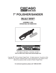
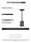
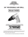
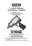
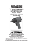
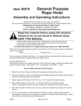
AIR FILTER SYSTEM - REMOTE CONTROL
Model 46361
OPERATING INFORMATION
®
3491 Mission Oaks Blvd., Camarillo, CA 93011
Visit our Web site at http://www.harborfreight.com
Copyright 2001 by Harbor Freight Tools ® . All rights reserved. No portion of this
manual or any artwork contained herein may be reproduced in any shape or form without the express written consent of Harbor Freight Tools.
For technical questions please call 1-800-444-3353
SPECIFICATIONS TABLE
%
!
**+
67+
&%
%
<+;
&%?@
&6?@
&;
%E
!
"##$
&
'&()
/5'&
8:;'
)
=>/=>=
D=>=>=
8=>8D=
=
7'
SAVE THIS MANUAL
You will need this manual for the safety warnings and precautions, operating and
maintenance procedures, parts list and diagram. Keep your invoice with this
manual. Write the invoice number on the inside of the front cover. Keep this
manual and invoice in a safe and dry place for future reference.
SAFETY WARNINGS AND PRECAUTIONS
1.
KEEP WORK AREA CLEAN AND DRY. Cluttered, damp or wet work areas
invite injuries.
2.
KEEP CHILDREN AWAY FROM WORK AREA. Do not allow children to handle
this product.
3.
STORE IDLE EQUIPMENT. When not in use, tools and equipment should be
stored in a dry location to inhibit rust. Always lock up tools and equipment and
keep out of reach of children.
4.
DO NOT USE THIS PRODUCT IF UNDER THE INFLUENCE OF ALCOHOL OR
DRUGS. Read warning labels on prescriptions to determine if your judgement or
reflexes are impaired while taking drugs. If there is any doubt, do not attempt to
use this product.
5.
INDUSTRIAL APPLICATIONS MUST FOLLOW OSHA REQUIREMENTS.
SKU 46361
PAGE 2
REV 07/03
6.
CHECK FOR DAMAGED PARTS. Before using this product, carefully check that
the Air Filter System will operate properly and perform its intended function.
Check for damaged parts and any other conditions that may affect the operation
of this machine. Replace or repair damaged or worn parts immediately.
7.
REPLACEMENT PARTS AND ACCESSORIES. When servicing, use only
identical replacement parts. Only use accessories intended for use with this
product. Approved accessories are available from Harbor Freight Tools.
8.
MAINTAIN THIS PRODUCT WITH CARE. Keep this product clean and dry for
better and safer performance.
9.
MAINTENANCE: For your safety, service and maintenance should be performed
regularly by a qualified technician.
10.
USE THE RIGHT PRODUCT FOR THE RIGHT JOB. There are certain applications for which this product was designed. Do not use small equipment to do the
work of larger industrial equipment. Do not use this product for a purpose for
which it was not intended.
11.
WARNING: The warnings, cautions, and instructions discussed in this manual
cannot cover all possible conditions and situations that may occur. It must be
understood by the operator that common sense and caution are factors which
cannot be built into this product, but must be supplied by the operator.
SPECIFIC PRODUCT WARNINGS AND PRECAUTIONS
1.
IF PLACING THE AIR FILTER SYSTEM ON A TABLE OR SHELF, MAKE
SURE THE MACHINE IS PLACED SECURELY ON A FLAT, LEVEL, STURDY
TABLE OR SHELF CAPABLE OF SUPPORTING THE WEIGHT OF THE
MACHINE.
2.
IF ATTACHING THE AIR FILTER SYSTEM TO A CEILING OR WALL, MAKE
SURE THE MACHINE IS ATTACHED SECURELY TO CEILING JOISTS
CAPABLE OF SUPPORTING THE WEIGHT OF THE MACHINE.
3.
ALWAYS DISCONNECT THIS MACHINE FROM ITS ELECTRICAL SUPPLY
SOURCE BEFORE PERFORMING ANY SERVICES OR MAINTENANCE. Make
sure to turn off the Air Filter System prior to it being cleaned, replacing the Filter
Net (part #1), etcetera.
4.
GROUND THIS MACHINE. The electrical power cord for this product is equipped
with a grounded, 3-prong plug. Make sure this product is always plugged into a
grounded, 3-hole electrical receptacle.
SKU 46361
PAGE 3
5.
MAKE SURE THE POWER SWITCH (part #19) IS IN THE “OFF” POSITION
BEFORE PLUGGING IN THE POWER CORD.
6.
DO NOT ABUSE THE POWER CORD. Do not yank the Power Cord (part #8) to
disconnect it from the electrical receptacle. Do not move this machine with the
power cord in the outlet. Keep the cord away from heat, oil, and sharp edges.
7.
IF YOU USE AN EXTENSION CORD, MAKE SURE TO USE ONLY UL APPROVED CORDS HAVING THE CORRECT GAUGE AND LENGTH.
(SEE FIGURE A.)
6 8
8D
D8
8
8
]
:
:
/
> #7%E
]
]
]
]
:
:
/
:
/
/
8
8
8
8
]
8
8
8
8
FIGURE A
8.
KEEP THE FILTER NET (part #1) AND FILTER BAG (part #2) CLEAN, IN
PLACE, AND IN WORKING ORDER.
9.
DO NOT PUT ANY OBJECT(S) INTO THE VENTILATION OPENINGS.
10.
MAINTAIN A SAFE WORK ENVIRONMENT. Do not use this product in or near
damp or wet areas. Do not expose this product to rain. Keep work area well lit.
Make sure there is adequate surrounding work space. Use this product in a well
ventilated area. Do not operate this product in the presence of flammable liquids,
gasses, or dust. To avoid accidental electric shock, do not let your body come in
contact with grounded surfaces such as pipes, radiators, ranges, etcetera.
11.
WARNING: People with pacemakers should consult with their physician(s)
before using this product. Operation of equipment in close proximity to a heart
pacemaker could cause interference or failure of the pacemaker. (California
Health & Safety Code 25249.5, et seq.)
12.
WARNING: This product contains or, when used, produces a chemical known to
the State of California to cause cancer and birth defects or other reproductive
harm. (California Health & Safety Code 25249.5, et seq.)
SKU 46361
PAGE 4
UNPACKING
When unpacking, check to make sure all parts shown on the Parts List (page 11) are
included. If any parts are missing or broken, please call Harbor Freight Tools at the
number shown on the cover of this manual as soon as possible.
ASSEMBLY AND OPERATING INSTRUCTIONS
NOTE: All parts listed below refer to the parts listed and shown on pages 10 and
11 of this manual.
Placement Of The Air Filter System:
1.
Caution: Make sure the Air Filter System is unplugged from its electrical supply
source before moving or placing the machine in a particular location.
2.
Caution: If placing the Air Filter System on a table or shelf, make sure the machine is placed securely on a flat, level, sturdy table or shelf capable of supporting the weight of the machine.
3.
Caution: If attaching the Air Filter System to a ceiling, make sure the machine is
attached securely to ceiling joists capable of supporting the weight of the machine.
4.
To attach the Air Filter System to a ceiling; locate the four Hangers (part #31) that
are threaded into the four Nuts (#32) attached to the top edges of the machine.
(See Figure B, and Assy. Diagram.)
HANGER (#31)
NUT (#32)
FIGURE B
SKU 46361
PAGE 5
REV 07/03
5.
Locate the desired ceiling location, and ceiling joists, upon which to attach the Air
Filter System.
6.
With assistance and proper lifting equipment (not provided), raise the Air Filter
System to the desired ceiling location. Caution: Make sure all other people are
kept well clear of the surrounding area during this procedure.
7.
Align the four Hangers (part #31) with the ceiling joists and measure for eyelet
bolt location. Then insert four eyelet bolts (not included) throught the ceiling into
the underside of the ceiling joists. Note: Eyelet bolts must be of a size that are
capable of safely supporting the weight of the Air Filter System. When hanging
the Air Filter System, make sure each Hanger fits completely inside the loop of
each eyelet bolt to insure a safe mounting of the Air Filter System. (See Figure
C, and Assy. Diagram.)
CEILING JOISTS
CEILING
Air Filter System
EYELET BOLT
(not included)
HANGER (#31)
FIGURE C
The Manual Power Switch And Remote Control:
1.
The Air Filter System is equipped with a manual Power Switch (part #19) and a
hand held Remote Control (part #34). (See Figures D, E, and Assy. Diagram.)
3A CIRCUIT BREAKER
Remote Control
(#34)
POWER SWITCH (#19)
FIGURE D
SKU 46361
PAGE 6
REV 07/03
2.
When the manual Power Switch (part #19) is turned to its “NON-REMOTE CONTROL” position, the Air Filter System will run continuously until the manual Power
Switch is turned to its “REMOTE CONTROL” position. The Air Filter System will
then automatically shut off. (See Figures D, G, and Assy. Diagram.)
3.
The Air Filter System may also be operated by a hand held Remote Control (part
#34). The Remote Control has an operating range of up to 25 feet. (See Figure
E, and Assy. Diagram.)
REMOTE CONTROL (#34)
(FRONT)
REMOTE CONTROL (#34)
(BACK)
BATTERY LEAD
9 VOLT BATTERY
BATTERY
COVER
SKU 46361
PAGE 7
FIGURE E
REV 09/02 REV 03/03 REV 07/03
4.
NOTE: The Remote Control requires a 9 Volt battery. To install a 9 Volt battery in
the Remote Control, remove the Battery Cover located on the back of the Remote
Control and connect the battery poles to the Battery Lead on the Remote Control.
Then, replace the Battery Cover. (See Figure E, and Assy. Diagram.)
5.
To begin using the Remote Control (part #34) feature, turn the Power Switch
(part #19) to its “REMOTE CONTROL” position and leave it in that position.
Then, to turn the Air Filter System on, press the “ON” button located on the
Remote Control. To turn the Air Filter System off, press the “OFF” button located
on the Remote Control. (See Figure E, G, and Assy. Diagram.)
POWER SWITCH (#19)
3A CIRCUIT BREAKER
NON-REMOTE
CONTROL
POSITION
REMOTE
CONTROL
POSITION
POWER CORD (#8)
FIGURE G
SWITCH PLATE
SKU 46361
PAGE 8
REV 09/02
REV 07/03
CLEANING AND MAINTENANCE
1.
Caution: Always disconnect the Air Filter System from its electrical supply
source before performing any cleaning, servicing, or maintenance.
2.
Before each use, inspect the general condition of the Air Filter System. Check
for loose screws, misalignment, binding of moving parts, broken parts, loose or
damaged electrical power cord, and any other condition that may affect its safe
operation. If abnormal noise or vibration occurs, disconnect the Air Filter System
from its electrical supply source immediately and have the problem corrected
before further use. Do not use damaged equipment.
3.
Periodically, inspect the Filter Net (part #1) for dirt and debris and, if necessary,
remove and change the Filter Net. The Filter Net is located at the rear of the Air
Filter System unit. To remove the Filter Net, unlock the two Clips located on the
rear/top and bottom panels of the unit. Then, remove the Filter Net to inspect its
condition. Then, replace the old (or new) Filter Net in the rear of the unit and lock
it back in place with the two Clips. (See Figure H.)
CLIP
AIR FILTER SYSTEM
(REAR VIEW)
CLIP
4.
FILTER NET (#1)
FIGURE H
Periodically, inspect the Filter Bag (part #2) for dirt and debris and, if necessary,
remove and clean the Filter Bag. The Filter Bag is located at the rear of the Air
Filter System unit. To remove the Filter Bag, unlock the two Clips located on the
rear/top and bottom panels of the unit. Remove the Filter Net (part #1). Then,
remove the Filter Bag to inspect its condition. If necessary, use compressed air
to blow the dirt and debris from the Filter Bag. Caution: During this procedure,
make sure to wear ANSI approved safety impact glasses, ANSI approved hearing
protection, and ANSI approved dust protection. ANSI approved safety impact
glasses, ANSI approved hearing protection, and ANSI approved dust protection
are available from Harbor Freight Tools. Then, replace the Filter Bag and Filter
Net in the rear of the unit and lock them back in place with the two Clips. (See
Figures H, I, and Assy. Diagram.)
SKU 46361
PAGE 9
FILTER BAG (#2)
FIGURE I
5.
If necessary, wipe the outside of the Air Filter System with a damp cloth. You
may use a mild detergent.
PLEASE READ THE FOLLOWING CAREFULLY
THE MANUFACTURER AND/OR DISTRIBUTOR HAS PROVIDED THE PARTS DIAGRAM
IN THIS MANUAL AS A REFERENCE TOOL ONLY. NEITHER THE MANUFACTURER NOR
DISTRIBUTOR MAKES ANY REPRESENTATION OR WARRANTY OF ANY KIND TO THE
BUYER THAT HE OR SHE IS QUALIFIED TO MAKE ANY REPAIRS TO THE PRODUCT
OR THAT HE OR SHE IS QUALIFIED TO REPLACE ANY PARTS OF THE PRODUCT. IN
FACT, THE MANUFACTURER AND/OR DISTRIBUTOR EXPRESSLY STATES THAT ALL
REPAIRS AND PARTS REPLACEMENTS SHOULD BE UNDERTAKEN BY CERTIFIED
AND LICENSED TECHNICIANS AND NOT BY THE BUYER. THE BUYER ASSUMES ALL
RISK AND LIABILITY ARISING OUT OF HIS OR HER REPAIRS TO THE ORIGINAL
PRODUCT OR REPLACEMENT PARTS THERETO, OR ARISING OUT OF HIS OR HER
INSTALLATION OF REPLACEMENT PARTS THERETO.
Parts Diagram
34
SKU 46361
PAGE 10
PARTS LIST
Power Cord
34
REMOTE CONTROL
1
NOTE: Some parts are listed and shown for illustration purposes only, and are not
available individually as replacement parts.
SKU 46361
PAGE 11
REV 07/03