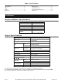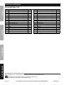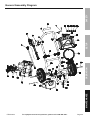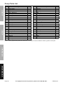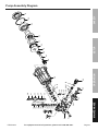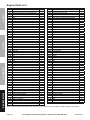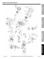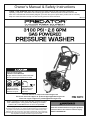
1
Owner’s Manual & Safety Instructions
Save This Manual Keep this manual for the safety warnings and precautions, assembly,
operating, inspection, maintenance and cleaning procedures. Write the product’s serial number in the
back of the manual near the assembly diagram (or month and year of purchase if product has no number).
Keep this manual and the receipt in a safe and dry place for future reference.
REV 15a
Using an engine indoors
CAN KILL YOU IN MINUTES.
Engine exhaust contains carbon monoxide.
This is a poison you cannot see or smell.
NEVER use inside
a home or garage,
EVEN IF doors and
windows are open.
Only use OUTSIDE
and far away from
windows, doors,
and vents.
Visit our website at: http://www.harborfreight.com
Email our technical support at: [email protected]
Email our engine support at: [email protected]
When unpacking, make sure that the product is intact
and undamaged. If any parts are missing or broken,
please call 1-888-866-5797 as soon as possible.
Copyright© 2014 by Harbor Freight Tools®. All rights reserved.
No portion of this manual or any artwork contained herein may be reproduced in
any shape or form without the express written consent of Harbor Freight Tools.
Diagrams within this manual may not be drawn proportionally. Due to continuing
improvements, actual product may differ slightly from the product described herein.
Tools required for assembly and service may not be included.
Read this material before using this product.
Failure to do so can result in serious injury.
SAVE THIS MANUAL.
Table of Contents
Specifications.............................................. 2
Safety��������������������������������������������������������� 3
Setup........................................................... 7
Operationr��������������������������������������������������� 12
Maintenances���������������������������������������������� 17
Troubleshooting.......................................... 20
Parts Lists and Diagrams........................... 24
Warranties.................................................. 30
Specifications
Pressure Washer Specifications
Pump
Drive
Maximum Pressure
Flow Rate
Hose Length
Wand Length
Nozzles
Axial
Direct
3100 PSI
2.8 GPM
25'
21"
Quick Connect 0°, 15°,
25°, 40° + Soap Nozzle
Engine Specifications
Displacement
Engine Type
Cooling System
Fuel
Engine Oil
Type
Capacity
Type SAE
Capacity
Run Time @ 50% Load
with full tank
Bore x Stroke
Compression Ratio
Rotation viewed from PTO
(power takeoff - the output shaft)
Spark Plug
Valve Clearance
Speed
212 cc
Horizontal Single Cylinder
4-stroke OHV
Forced air cooled
87+ octane stabilizer treated
unleaded gasoline
0.95 Gallon (3.6 Liter)
10W-30 above 32° F
5W-30 at 32° F or below
0.5 Quart (0.5 Liter)
3 hr.
70 mm x 55 mm
8.5:1
Counterclockwise
Type
NGK® BP-6ES
NHSP® / Torch® F6TC
Gap
Intake
Exhaust
Idle
0.7 – 0.8 mm
0.10 – 0.15 mm
0.15 – 0.20 mm
1800± 50 RPM
The emissions control system for this Engine is warranted for standards set by the
U.S. Environmental Protection Agency and by the California Air Resources Board (also known as CARB).
For warranty information, refer to the last pages of this manual.
Page 2
For equipment technical questions, please call 1-888-866-5797.
ITEM 62214
WARNING SYMBOLS AND DEFINITIONS
This is the safety alert symbol. It is used to alert you to potential
personal injury hazards. Obey all safety messages that
follow this symbol to avoid possible injury or death.
Safety
Indicates a hazardous situation which, if not avoided,
will result in death or serious injury.
Indicates a hazardous situation which, if not avoided,
could result in death or serious injury.
Indicates a hazardous situation which, if not avoided,
could result in minor or moderate injury.
Addresses practices not related to personal injury.
RPM
HP
Property or Statement
Revolutions Per Minute
Horsepower
WARNING marking concerning
Risk of Eye Injury. Wear ANSI-approved
safety goggles with side shields.
Read the manual before
set-up and/or use.
WARNING marking concerning
Risk of Hearing Loss.
Wear hearing protection.
Symbol
Property or Statement
WARNING marking concerning
Risk of Respiratory Injury.
Operate engine OUTSIDE and far away
from windows, doors, and vents.
WARNING marking concerning
Risk of Fire while handling fuel.
Do not smoke while handling fuel.
WARNING marking concerning
Risk of Fire.
Do not refuel while operating.
Keep flammable objects
away from engine.
WARNING marking concerning
Risk of Injection.
Do not direct water stream/nozzle at body.
IMPORTANT SAFETY INSTRUCTIONS
Operation
Symbol
Setup
Symbol Definitions
WARNING! Read all instructions.
Failure to follow all instructions listed below may result in fire, serious injury and/or DEATH.
The warnings and precautions discussed in this manual cannot cover all possible conditions and
situations that may occur. It must be understood by the operator that common sense and caution
are factors which cannot be built into this product, but must be supplied by the operator.
Maintenance
SAVE THESE INSTRUCTIONS
ITEM 62214
For equipment technical questions, please call 1-888-866-5797.
Page 3
Set Up Precautions
Safety
1. Gasoline fuel and fumes are flammable, and
potentially explosive. Use proper fuel storage
and handling procedures. Do not store fuel
or other flammable materials nearby.
2. Have multiple ABC class fire extinguishers nearby.
3. Operation of this equipment may create sparks that
can start fires around dry vegetation.
A spark arrestor may be required. The operator
should contact local fire agencies for laws or
regulations relating to fire prevention requirements.
4. Set up and use only on a flat, level,
well‑ventilated surface.
5. The work area should have adequate
drainage to reduce the possibility of
a fall due to slippery surfaces.
6. Wear ANSI-approved safety goggles, heavy-duty
work gloves, and dust mask/respirator during set up.
7. Use only lubricants and fuel recommended
in the Specifications chart of this manual.
8. Only use cold water or pressure washer
detergent in this tool. Do not use caustic
materials, solvents, flammable materials, or
detergents not designed for pressure washers.
Use of any such material can cause injury,
or damage this tool or personal property.
9. Do not dry run this product. Dry running
will cause serious damage to the seals.
Make sure the water supply used for the
Pressure Washer is not dirty or sandy.
10. Prior to starting the Pressure Washer in
cold weather, check all of the parts of the
unit to make sure ice has not formed. Do
not store the unit anywhere that the
temperature will fall below 32° F (0° C).
Setup
Operating Precautions
CARBON MONOXIDE HAZARD
Using an engine indoors
CAN KILL YOU IN MINUTES.
Engine exhaust contains
carbon monoxide. This is a poison
you cannot see or smell.
1.
5. Do not carry the spray handle with your finger on
the trigger, whether engine is operating or not.
6. In case of an emergency during use, immediately
release the trigger on the spray handle, turn
the engine off and then shut off gas supply
to the engine. Do not set the spray handle
down without turning off the engine.
7. This Pressure Washer is intended for
outdoor residential use only.
Operation
8. The high pressure water flow can damage
the work surface if not used properly. Always
test the spray in an open area first.
NEVER use inside a home or garage,
EVEN IF doors and windows are open.
9. When dispensing detergent, apply the detergent
to the cleaning area at low pressure only.
Detergent dispensing only works when the
spray wand is in the low-pressure position.
10. Keep all spectators at least six feet
from the Engine during operation.
Only use OUTSIDE and far away from windows,
doors, and vents.
2. Keep children away from the equipment,
especially while it is operating.
Maintenance
3. Parts of the Pressure Washer, especially
exhaust system components, get very hot
during use. Stay clear of hot parts.
4.
Injection Hazard! The high pressure
water jet produced by this tool can cut
skin or cause injury to hands or eyes.
Do not allow spray to strike you and do
not spray toward people or animals. Do not spray
the tool itself or any electrical wiring/receptacle.
Page 4
11. Fire Hazard! Do not fill fuel tank while engine is
running. Do not operate if gasoline has been spilled.
Clean spilled gasoline before starting engine.
Do not operate near pilot light or open flame.
12. Do not touch engine during use.
Let engine cool down after use.
13. Do not leave the equipment unattended when it is
running. Turn off the equipment (and remove safety
keys, if available) before leaving the work area.
14. The equipment can produce high noise levels.
Prolonged exposure to noise levels
above 85 dBA is hazardous to hearing.
Wear ear protection when operating the equipment
or when working nearby while it is operating.
15. Wear ANSI-approved safety glasses
and hearing protection during use.
For equipment technical questions, please call 1-888-866-5797.
ITEM 62214
19. Stay alert, watch what you are doing and use
common sense when operating this piece of
equipment. Do not use while tired or under the
influence of drugs, alcohol or medication.
20. Do not overreach. Keep proper footing and
balance at all times. This enables better control
of the equipment in unexpected situations.
21. Use this equipment with both hands only.
Using equipment with only one hand
can easily result in loss of control.
22. Dress properly. Do not wear loose clothing or
jewelry. Keep hair, clothing and gloves away
from moving parts. Loose clothes, jewelry or
long hair can be caught in moving parts.
23. Do not cover the engine or
equipment during operation.
24. Keep the equipment, engine, and
surrounding area clean at all times.
27. WARNING: This product contains or, when
used, produces a chemical known to the State
of California to cause cancer and birth defects
or other reproductive harm. (California Health
& Safety Code § 25249.5, et seq.)
28. WARNING: The brass components of this product
contain lead, a chemical known to the State
of California to cause cancer and birth defects
or other reproductive harm. (California Health
& Safety Code § 25249.5, et seq.)
29. When spills of fuel or oil occur, they must be
cleaned up immediately. Dispose of fluids and
cleaning materials as per any local, state, or
federal codes and regulations. Store oil rags in
a bottom-ventilated, covered, metal container.
30. Keep hands and feet away from moving parts. Do
not reach over or across equipment while operating.
31. Before use, check for misalignment or binding of
moving parts, breakage of parts, and any other
condition that may affect the equipment’s operation.
If damaged, have the equipment serviced
before using. Many accidents are caused
by poorly maintained equipment.
32. Use the correct equipment for the application.
Do not modify the equipment and do not use the
equipment for a purpose for which it is not intended.
Vibration Precautions
This tool vibrates during use. Repeated or
long-term exposure to vibration may cause
temporary or permanent physical injury,
particularly to the hands, arms and shoulders.
To reduce the risk of vibration-related injury:
1. Anyone using vibrating tools regularly or for an
extended period should first be examined by a
doctor and then have regular medical checkups to ensure medical problems are not being
caused or worsened from use. Pregnant women
or people who have impaired blood circulation
to the hand, past hand injuries, nervous system
disorders, diabetes, or Raynaud’s Disease should
not use this tool. If you feel any medical or
physical symptoms related to vibration (such as
tingling, numbness, and white or blue fingers),
seek medical advice as soon as possible.
ITEM 62214
Setup
18. Do not operate in explosive atmospheres,
such as in the presence of flammable
liquids, gases, or dust. Gasoline-powered
engines may ignite the dust or fumes.
26. Do not operate the equipment with known
leaks in the engine’s fuel system.
2. Do not smoke during use. Nicotine reduces
the blood supply to the hands and fingers,
increasing the risk of vibration-related injury.
Operation
17. Use only accessories that are recommended
by Harbor Freight Tools for your model.
Accessories that may be suitable for one
piece of equipment may become hazardous
when used on another piece of equipment.
25. Use the equipment, accessories, etc., in
accordance with these instructions and in the
manner intended for the particular type of
equipment, taking into account the working
conditions and the work to be performed.
Use of the equipment for operations different from
those intended could result in a hazardous situation.
3. Wear suitable gloves to reduce the
vibration effects on the user.
4. Use tools with the lowest vibration when there
is a choice between different processes.
5. Include vibration-free periods each day of work.
6. Grip tool as lightly as possible (while still keeping
safe control of it). Let the tool do the work.
7. To reduce vibration, maintain the tool as
explained in this manual. If any abnormal
vibration occurs, stop use immediately.
For equipment technical questions, please call 1-888-866-5797.
Page 5
Maintenance
16. People with pacemakers should consult their
physician(s) before use. Electromagnetic fields in
close proximity to a heart pacemaker could cause
pacemaker interference or pacemaker failure.
Caution is necessary when near the
engine’s magneto or recoil starter.
Safety
Operating Precautions (continued)
Service Precautions
1. Before service, maintenance, or cleaning:
a. Turn the engine switch to its “OFF” position.
Safety
b. Allow the engine to completely cool.
c. Then, remove the spark plug cap
from the spark plug.
2. Keep all safety guards in place and in
proper working order. Safety guards include
muffler, air cleaner, mechanical guards,
and heat shields, among other guards.
3. Do not alter or adjust any part of the
equipment or its engine that is sealed by the
manufacturer or distributor. Only a qualified
service technician may adjust parts that may
increase or decrease governed engine speed.
4. Wear ANSI-approved safety goggles,
heavy‑duty work gloves, and
dust mask/respirator during service.
Setup
5. Keep the high pressure hose connected to
the pressure washer and spray gun while the
system is pressurized. Disconnecting the
pressure hose while the unit is pressurized
is dangerous, and may cause injury.
10. Have the equipment serviced by a qualified repair
person using only identical replacement parts.
This will ensure that the safety of the equipment
is maintained. Do not attempt any service or
maintenance procedures not explained in this
manual or any procedures that you are uncertain
about your ability to perform safely or correctly.
11. Store equipment out of the reach of children.
12. Follow scheduled engine and
equipment maintenance.
Refueling:
1. Do not smoke, or allow sparks, flames,
or other sources of ignition around the
equipment, especially when refuelling.
2. Do not refill the fuel tank while the
engine is running or hot.
3. Do not fill fuel tank to the top.
Leave a little room for the fuel to expand as needed.
TO PREVENT FUEL LEAKAGE AND
FIRE HAZARD, do not fill fuel above
the bottom of fuel strainer.
6. Do not allow the high pressure hose to come
in contact with any hot part of the unit. The
hose might be damaged, possibly causing
it to burst or leak under high pressure.
7. Maintain labels and nameplates on the equipment.
These carry important information.
If unreadable or missing, contact
Harbor Freight Tools for a replacement.
Operation
8. If water is leaking out of the Pressure Washer
immediately turn off the unit. Unplug the
Pressure Washer, and discharge all pressure
before tightening fittings or having repair
work done by a qualified technician.
9. When the engine is running, do not allow
the Pressure Washer to remain idle for more
than two minutes. If allowed to remain idle,
the water in the unit will heat up, possibly
causing damage to the Pressure Washer.
Max Fuel
DO NOT OVERFILL!
4. Refuel in a well-ventilated area only.
5. Wipe up any spilled fuel and allow excess
to evaporate before starting engine.
To prevent FIRE, do not start the engine
while the smell of fuel hangs in the air.
SAVE THESE INSTRUCTIONS.
Maintenance
Page 6
For equipment technical questions, please call 1-888-866-5797.
ITEM 62214
Set Up
TO PREVENT SERIOUS INJURY:
Operate only with proper spark arrestor installed.
Operation of this equipment may create sparks that can start fires around dry vegetation.
A spark arrestor may be required.
The operator should contact local fire agencies for laws or regulations
relating to fire prevention requirements.
Safety
Read the ENTIRE IMPORTANT SAFETY INFORMATION section at the beginning of this manual
including all text under subheadings therein before set up or use of this product.
TO PREVENT SERIOUS INJURY FROM ACCIDENTAL STARTING: Turn the Power Switch
of the equipment to its “OFF” position, wait for the engine to cool, and unplug the spark
plug wire(s) before assembling or making any adjustments to the equipment.
Note: For additional information regarding the parts listed in the following pages,
refer to the Assembly Diagrams near the end of this manual.
Setup
Assembly
Handle
2. Attach the Spray Gun Holder (3)
to the Handle with a Knob (4).
Hose Hanger
Knob
Handle Knob
Operation
1. Attach the Handle (5) onto
the Frame (13) with the
Handle Knobs (12).
Spray Gun
Holder
3. Attach the Hose Hanger (7) to
the Handle with a Knob (4).
Frame
4. Attach the two Wand Holders (14)
to the Frame using Bolts (20).
Wand Holder
Wand Holder
Maintenance
Bolt
Bolt
Figure A
ITEM 62214
For equipment technical questions, please call 1-888-866-5797.
Page 7
Assembly (continued)
Safety
5. Connect the Pressure Hose (15) to the
outlet fitting on the Pump (32) and firmly
hand-tighten the nut. See Figure B.
Figure B
6. Connect the Pressure Hose to the handle
of the Spray Gun (2) and firmly handtighten the nut. See Figure C.
Setup
Figure C
Wand
7. Remove the protective cap on the Wand (1)
inlet. Insert the Wand into the Spray Gun tip
and firmly hand-tighten the nut. See Figure D.
Spray
Gun Tip
Figure D
Operation
Nozzle
8. Attach the Nozzle (8) to the Wand by
pulling back the quick connect collar and
pushing the Nozzle onto the end of the
Wand. Make sure the quick connect collar
locks the Nozzle in place. See Figure E.
Quick Connect
Collar
Wand
Figure E
Maintenance
9. Connect the water supply hose to the water inlet
connection on the Pump (32) and hand-tighten
the Inlet Fitting. See Figure F.
The water source must be able to provide a
minimum of five gallons of clean, cold water per
minute at 20 PSI. Only use a 5/8" inner diameter
(or larger) hose that is rated to meet this capacity.
Water
Supply
Hose
Inlet
Fitting
Figure F
Page 8
For equipment technical questions, please call 1-888-866-5797.
ITEM 62214
Spray Gun
Handle
Safety
Components and Controls
Handle
Spray Gun
Trigger
Pressure
Hose
Trigger
Lock
Nozzles
Setup
Wand
Frame
Engine
Pump
Detergent
Tank Lid
Operation
Detergent
Tank
Thermal
Relief Valve
ITEM 62214
Maintenance
Pump Outlet
Fitting
Water Inlet
Fitting
For equipment technical questions, please call 1-888-866-5797.
Page 9
Engine Controls
Safety
Air Filter
Fuel Cap
Setup
Starter
Handle
Muffler
Oil Drain Plug
Operation
Throttle
Choke
Fuel Valve
Engine
Switch
Maintenance
Oil Cap/Dipstick
Page 10
For equipment technical questions, please call 1-888-866-5797.
ITEM 62214
High Altitude Operation Above 3000 feet
NOTICE: Warranty void if necessary adjustments are not made for high altitude use.
At high altitudes, the engine’s carburetor, governor (if so equipped), and any other parts that control the fuel-air
ratio will need to be adjusted by a qualified mechanic to allow efficient high-altitude use and to prevent damage
to the engine and any other devices used with this product. The fuel system on this engine may be influenced by
operation at higher altitudes. Proper operation can be ensured by installing an altitude kit at altitudes higher than
3000 ft. above sea level. At elevations above 8000 ft, the engine may experience decreased performance, even
with the proper main jet. Operating this engine without the proper altitude kit installed may increase the engine’s
emissions and decrease fuel economy and performance. The kit should be installed by a qualified mechanic.
Safety
WARNING! TO PREVENT SERIOUS INJURY FROM FIRE:
Follow instructions in a well-ventilated area away from ignition sources.
If the engine is hot from use, shut the engine off and wait for it to cool before proceeding. Do not smoke.
1. Turn off the engine.
2. Close the fuel valve.
3. Place a bowl under the fuel cup to catch any spilled fuel.
CAUTION! Carburetor bowl may have gas in it which will leak upon removing the bolt.
5. Remove the bolt, Bolt Seal, fuel cup, Fuel Cup Seal and Main Jet from the body of the carburetor assembly.
A carburetor screwdriver (not included) is needed to remove and install the Main Jet.
Note: The mixing tube is held in place by the Main Jet and might fall out when it is removed.
If it falls out, replace it in the same orientation before replacing the Main Jet.
Setup
4. Unthread the bolt holding the fuel cup.
6. Replace the Main Jet with the replacement Main Jet needed for your altitude range (part 1a or 2a).
Note: The Fuel Cup Seal and Bolt Seal may be damaged during removal
and should be replaced with the new ones from the kit.
7. Replace the Fuel Cup Seal (4a), fuel cup, Bolt Seal (3a), and bolt. Tighten in place.
8. Wipe up any spilled fuel and allow excess to evaporate
before starting engine. To prevent FIRE, do not start the
engine while the smell of fuel hangs in the air.
High Altitude Kit Parts List - A
Part
1a
2a
3a
4a
Description
Main Jet 3000-6000 ft.
Main Jet 6000-8000 ft.
Bolt Seal
Fuel Cup Seal
Qty
1
1
1
2
Carburetor
Assembly
Fuel Cup Seal
Mixing Tube
(might remain
inside carburetor)
Operation
CAUTION: Do not cross thread bolt when tightening.
Finger tighten first and then use a wrench to make sure the bolt is properly threaded.
Main Jet
Fuel Cup
Maintenance
Bolt Seal
Bolt
ITEM 62214
For equipment technical questions, please call 1-888-866-5797.
Page 11
Operation
Read the ENTIRE IMPORTANT SAFETY INFORMATION section at the beginning of this manual
including all text under subheadings therein before set up or use of this product.
Safety
Pre-Start Checks
Inspect engine and equipment looking for damaged, loose, and missing parts before set up and starting.
If any problems are found, do not use equipment until fixed properly.
Checking and Filling Engine Oil
NOTICE: Your Warranty is VOID if the engine’s
crankcase is not properly filled with oil before
each use. Before each use, check the oil level.
Do not run the engine with low or no engine oil.
Running the engine with no or low engine oil
WILL permanently damage the engine.
Full level
Full level
1. Make sure the engine is stopped and is level.
2. Close the Fuel Valve.
Setup
3. Clean the top of the Dipstick and the area around it.
Remove the Dipstick by turning it counterclockwise,
and wipe it off with a clean, lint free rag.
4. Reinsert the Dipstick without threading it in and
remove it to check the oil level. The oil level
should be up to the full level as shown above.
5. If the oil level is at or below the low mark add the
appropriate type of oil until the oil level is at the
proper level. SAE 10W‑30 oil is recommended for
general use. (The SAE Viscosity Grade chart on
page 18 in the Maintenance section shows other
viscosities to use in different average temperatures.)
6. Thread the dipstick back in clockwise.
NOTICE: Do not run the engine with too little oil.
The engine will be permanently damaged.
Checking and Filling Fuel
Operation
WARNING! TO PREVENT SERIOUS
INJURY FROM FIRE:
Fill the fuel tank in a well-ventilated area
away from ignition sources. If the engine
is hot from use, shut the engine off and
wait for it to cool before adding fuel. Do not smoke.
1. Clean the Fuel Cap and the area around it.
2. Unscrew and remove the Fuel Cap.
3. Remove the Strainer and remove any dirt
and debris. Then replace the Strainer.
Note: Do not use gasoline containing more than
10% ethanol (E10). Do not use E85 ethanol.
Note: Do not use gasoline that has been stored in a
metal fuel container or a dirty fuel container. It can
cause particles to enter the carburetor, affecting
engine performance and/or causing damage.
4. If needed, fill the Fuel Tank to about 1 inch under
the fill neck of the Fuel Tank with 87 octane or
higher unleaded gasoline that has been treated
with a fuel stabilizer additive. Follow fuel stabilizer
manufacturer’s recommendations for use.
5. Then replace the Fuel Cap.
6. Wipe up any spilled fuel and allow excess
to evaporate before starting engine.
To prevent FIRE, do not start the engine
while the smell of fuel hangs in the air.
Maintenance
Page 12
For equipment technical questions, please call 1-888-866-5797.
ITEM 62214
Starting the Engine
a. Inspect the equipment and engine.
b. Fill the engine with the proper amount and type of both unleaded gasoline and oil.
c. TURN ON WATER SUPPLY, REMOVE NOZZLE, POINT WAND IN SAFE DIRECTION, AND HOLD
DOWN TRIGGER UNTIL ALL AIR IS RELEASED FROM THE SYSTEM, AT LEAST 30 SECONDS.
Then release the Trigger, lock it in the safety position and replace Nozzle before starting engine.
Manual Start
1. To start a cold engine, move the Choke to the
START position.
To restart a warm engine, leave the Choke in the
RUN position.
Safety
Before Starting the Engine
Setup
1
2. Open the Fuel Valve.
3
Note: Some tools have a Speed Control Lever located
elsewhere on the tool which functions the same as the
Throttle. Use the Speed Control Lever in place of the
Throttle when the tool is so equipped.
O
OFF
4. Turn the Engine Switch on.
ITEM 62214
ON
ON
I
4
For equipment technical questions, please call 1-888-866-5797.
Page 13
Maintenance
3. Slide the Throttle or Speed Control Lever to 1/3
away from the SLOW position (the “turtle”).
Operation
2
Starting the Engine (continued)
Safety
5. Grip the Starter Handle of the Engine loosely and pull
it slowly two times to allow the gasoline to flow into
the Engine’s carburetor. Then pull the Starter Handle
gently until resistance is felt. Allow Cable to retract fully
and then pull it quickly. Repeat until the engine starts.
5
Note: Do not let the Starter Handle snap back against the engine.
Hold it as it recoils so it doesn't hit the engine.
6. Allow the Engine to run for several seconds.
Then, if the Choke lever is in the START position,
move the Choke Lever very slowly to its RUN position.
6
Setup
Note: Moving the Choke Lever too
fast could stall the engine.
7. Adjust the Throttle as needed.
Break-in Period:
a. Breaking-in the engine will help to ensure proper equipment and engine operation.
b. The operational break-in period will last about 3 hours of use. During this period:
• Do not apply a heavy load to the equipment.
• Do not operate the engine at its maximum speed.
c. The maintenance break-in period will last about 20 hours of use.
Operation
• Change the engine oil after this period.
Under normal operating conditions subsequent maintenance follows
the schedule explained in the Maintenance section.
Maintenance
Page 14
For equipment technical questions, please call 1-888-866-5797.
ITEM 62214
CAUTION
Use the Pressure Washer only on surfaces
able to withstand the force of the spray.
1. Choose the Nozzle that best meets the needs of
the job. See Chart below. Only use the Nozzles
on surfaces capable of withstanding the force of
the spray. Only use the Black Nozzle when using
pressure washer detergent. The power of the
other Nozzles will propel mist back at the operator
and can embed detergent into the surface.
nozzle selection chart
nozzle
use for
Use with pressure
Black – Low Pressure
washer detergent.
Moderate cleaning for
White – Wide Spray
autos and boats.
Standard cleaning for
Green – Medium Spray
driveways and paint removal.
Heavy cleaning for
Yellow – Narrow Spray
decks and siding.
Intense cleaning for stubborn
stains and dirt. Use only on
Red – Pencil Spray
hard surfaces – can damage
concrete, wood, paint, etc.
2. Pull back the quick connect collar and push the
Nozzle onto the end of the Wand. Make sure the
quick connect collar locks the Nozzle in place.
If using detergent:
5. Hold the Wand at about a 45° angle when
cleaning; spraying the surface directly could
embed dirt into the surface (especially with
the high pressure Nozzles). Spray at a
distance of about three to five feet.
6. Clean vertical and sloped surfaces
from the top down.
7. When cleaning horizontal surfaces, occasionally
use the stream to clear the area of excess water.
CAUTION! Do not allow the Pressure Washer
to idle without the Trigger held down for more than
two minutes. The water will heat up and damage the
Pressure Washer. RISK OF BURNS! The Pump
will expel very hot water if allowed to idle too long.
Note: During normal operation the Thermal Relief Valve
may release small amounts of water intermittently.
8. Hold the Trigger down and move the Wand back
and forth slowly and steadily to pressure wash the
surface. Take special care when spraying surfaces
made of two different materials (brick and mortar,
for example), so as to not damage the softer of
the two materials during pressure washing.
9. If the surface is streaked or uneven at the end
of a job, switch to a Nozzle that has a wider
spray pattern to blend the affected area.
Maintenance
Read detergent directions. Only use detergents
specified for use with pressure washers. Open
the Detergent Tank Lid, fill Detergent Tank with
prepared detergent solution and close the Lid. The
Pressure Washer will draw one gallon of detergent
for every seven gallons of water. Only use the Black
(low pressure) Nozzle when spraying detergents.
4. Start with a low pressure Nozzle, and gradually
use higher pressures as needed. Test spray the
edge of the surface to be cleaned first to make sure
that the stream is not too strong for the surface.
If the stream damages the surface, move further
away from the surface being cleaned to reduce the
pressure being applied to the surface. If the stream
is still too strong, lock the Trigger in the safety
position and change to a lower pressure Nozzle.
Setup
Do not direct spray from the Pressure Washer at a
person or an animal.
The water stream could cause serious injury.
3. With water supply on and Engine running
following directions in Starting the Engine
on page 13, unlock and hold down the
Trigger to start the stream. Be aware that
when it is first started, the gun will kick.
Operation
WARNING
Safety
Pressure Washer Operation
ITEM 62214
For equipment technical questions, please call 1-888-866-5797.
Page 15
Stopping the Engine and Pressure Washer
1. To stop the engine in an emergency,
turn the Engine Switch off.
Safety
OFF
2. Under normal conditions, use the following procedure:
O
I
a. Release the Trigger on the Spray Gun handle.
b. Slide the Throttle or Speed Control
Lever to SLOW (the “turtle”).
c. Turn the Engine Switch off.
d. Close the Fuel Valve.
e. Turn the water supply off.
3. Squeeze the Trigger to release excess pressure.
Setup
4. If pressure washer detergent has been used,
run clean water through the system to eliminate
detergent residue using the following procedure:
a. Turn off the Engine as detailed in step 2.
b. Fill the Detergent Tank with clean water.
c. Remove the Nozzle and restart the
Engine following directions in Starting
the Engine on page 13.
d. Point Wand in safe direction and hold down
Trigger to flush water through system until clean.
e. Turn off the Engine as detailed in step 2.
Folding and Storing
Operation
1. Disconnect the water supply hose from the
water inlet connection on the Pump.
Spray Gun
Handle Knobs
2. Drain all water out of the Pressure Washer and lock
the Trigger. Clean external parts with clean cloth.
3. Disconnect the Pressure Hose from the Pump
and Spray Gun, drain water from Hose and coil.
Handle
4. Loosen the nut and remove the
Wand from the Spray Gun.
Wand
5. Loosen Handle Knobs, fold Handle forward to a
horizontal position and tighten the Handle Knobs.
Maintenance
6. Clip the Wand into the Wand Holders
and hang the Spray Gun from the Spray
Gun Holder as shown in Figure G.
7. Store the equipment indoors out of children’s reach.
Figure G
NOTICE
Drain fuel at end of season or warranty is void.
See Long-Term Storage on page 20 for complete storage instructions.
Page 16
For equipment technical questions, please call 1-888-866-5797.
ITEM 62214
Maintenance
TO PREVENT SERIOUS INJURY FROM ACCIDENTAL STARTING:
Turn the Power Switch of the equipment to its “OFF” position, wait for the engine to cool, and disconnect
the spark plug cap before performing any inspection, maintenance, or cleaning procedures.
TO PREVENT SERIOUS INJURY FROM EQUIPMENT FAILURE:
Do not use damaged equipment. If abnormal noise, vibration, or excess
smoking occurs, have the problem corrected before further use.
Safety
WARNING
Follow all service instructions in this manual. The engine may fail critically if not serviced properly.
Many maintenance procedures, including any not detailed in this manual, will need to be performed
by a qualified technician for safety. If you have any doubts about your ability to safely service the
equipment or engine, have a qualified technician service the equipment instead.
Note: This maintenance schedule is intended solely as a general guide. If performance decreases or if
equipment operates unusually, check systems immediately. The maintenance needs of each piece of equipment
will differ depending on factors such as duty cycle, temperature, air quality, fuel quality, and other factors.
Note: The following procedures are in addition to the regular checks and maintenance
explained as part of the regular operation of the engine and equipment.
Before
Each Use
Procedure
Monthly or
Every 3 mo. or Every 6 mo. or
every 20
50 hr. of use 100 hr. of use
hr. of use
Yearly or
every 300
hr. of use
Every
2 Years
Setup
Cleaning, Maintenance, and Lubrication Schedule
Brush off outside of engine
Check engine oil level
Check air cleaner
Check sediment cup
Change engine oil
Check and clean spark plug
1. Check/adjust idle speed
*
2. Check/adjust valve clearance
3. Clean fuel tank, strainer
and carburetor
**
4. Clean carbon build-up from
combustion chamber
Replace fuel line if necessary
**
**
Operation
Clean/replace air filter
Maintenance
*Service more frequently when used in dusty areas. **These items should be serviced by a qualified technician.
ITEM 62214
For equipment technical questions, please call 1-888-866-5797.
Page 17
Safety
Checking and Filling Fuel
Engine Oil Change
WARNING! TO PREVENT SERIOUS
INJURY FROM FIRE:
Fill the fuel tank in a well-ventilated area
away from ignition sources. If the engine is
hot from use, shut the engine off and wait
for it to cool before adding fuel. Do not smoke.
CAUTION! Oil is very hot during operation and can
cause burns. Wait for engine to cool before changing oil.
1. Clean the Fuel Cap and the area around it.
2. Unscrew and remove the Fuel Cap.
3. Remove the Strainer and remove any dirt
and debris. Then replace the Strainer.
Note: Do not use gasoline containing more than
10% ethanol (E10). Do not use E85 ethanol.
Note: Do not use gasoline that has been stored in a
metal fuel container or a dirty fuel container. It can
cause particles to enter the carburetor, affecting
engine performance and/or causing damage.
Setup
4. If needed, fill the Fuel Tank to about 1 inch under
the fill neck of the Fuel Tank with 87 octane or
higher unleaded gasoline that has been treated
with a fuel stabilizer additive. Follow fuel stabilizer
manufacturer’s recommendations for use.
5. Then replace the Fuel Cap.
6. Wipe up any spilled fuel and allow excess
to evaporate before starting engine.
To prevent FIRE, do not start the engine
while the smell of fuel hangs in the air.
1. Make sure the engine is stopped and is level.
2. Close the Fuel Valve.
3. Place a drain pan (not included) underneath
the crankcase’s drain plug.
4. Remove the drain plug and, if possible,
tilt the crankcase slightly to help drain
the oil out. Recycle used oil.
5. Replace the drain plug and tighten it.
6. Clean the top of the Dipstick and the area around it.
Remove the Dipstick by turning it counterclockwise,
and wipe it off with a clean, lint free rag.
Full level
Full level
7. Add the appropriate type of oil until the oil level is at
the full level. SAE 10W‑30 oil is recommended for
general use.
The SAE Viscosity Grade chart shows other
viscosities to use in different average temperatures.
SAE Viscosity Grades
Pump Maintenance
30
Operation
The Pressure Washer Pump is maintenance free.
If any sign of oil leakage is present on or around
the Pump, DO NOT operate the Pressure Washer.
Have the unit serviced by a qualified technician.
10W-30
5W-30
-20
0
20
40
60
80
Average outdoor temperature
100°F
8. Thread the dipstick back in clockwise.
NOTICE: Do not run the engine with too little oil.
The engine will be permanently damaged.
Maintenance
Page 18
For equipment technical questions, please call 1-888-866-5797.
ITEM 62214
Spark Plug Maintenance
Air Filter Maintenance
1. Remove the Air Cleaner Cover and the air filter(s)
and check for dirt. Clean as described below.
Spark
Plug
Cap
1. Disconnect spark plug cap from end of plug.
Clean out debris from around spark plug.
2. Using a spark plug wrench, remove the spark plug.
3. Inspect the spark plug:
If the electrode is oily, clean it using a clean, dry rag.
If the electrode has deposits on it, polish it using
emery paper. If the white insulator is cracked or
chipped, the spark plug needs to be replaced.
• For paper filters:
To prevent injury from dust and debris,
wear ANSI-approved safety goggles,
NIOSH‑approved dust mask/respirator, and
heavy-duty work gloves. In a well‑ventilated
area away from bystanders, use pressurized
air to blow dust out of the filter. If this does not
get the filter clean, replace it.
• For foam filters:
Wash the filter in warm water and mild
detergent several times. Rinse. Squeeze out
excess water and allow it to dry completely.
Soak the filter in lightweight oil briefly,
then squeeze out the excess oil.
3. Install the cleaned filter(s). Secure the
Air Cleaner Cover before use.
Setup
Recommended Spark Plugs
NGK®
BP-6ES
NHSP® / TORCH®
Safety
2. Cleaning:
F6TC
NOTICE: Using an incorrect spark plug
may damage the engine.
4. When installing a new spark plug,
adjust the plug’s gap to the specification on the
Specifications chart. Do not pry against the
electrode, the spark plug can be damaged.
5. Install the new spark plug or
the cleaned spark plug into the engine.
Operation
• Gasket-style:
Finger-tighten until the gasket
contacts the cylinder head,
then tighten about 1/2-2/3 turn more.
• Non-gasket-style:
Finger-tighten until the plug
contacts the cylinder head,
then tighten about 1/16 turn more.
NOTICE: Tighten the spark plug properly.
If loose, the spark plug will cause the
engine to overheat.
If overtightened, the threads in the
engine block will be damaged.
ITEM 62214
For equipment technical questions, please call 1-888-866-5797.
Maintenance
6. Apply dielectric spark plug boot protector
(not included) to the end of the spark plug
and reattach the wire securely.
Page 19
Long-Term Storage
When the equipment is to remain idle for longer than
20 days, prepare the Engine for storage as follows:
Safety
1. CLEANING:
Wait for Engine to cool, then clean Engine with
dry cloth. NOTICE: Do not clean using water.
The water will gradually enter the Engine
and cause rust damage. Apply a thin coat
of rust preventive oil to all metal parts.
2. FUEL:
To protect the fuel tank during storage, fill the
tank with gasoline that has been treated with
a fuel stabilizer additive. Follow fuel stabilizer
manufacturer’s recommendations for use. Refer
to Checking and Filling Fuel on page 12.
Setup
WARNING! TO PREVENT SERIOUS
INJURY FROM FIRE:
Fill tank in a well-ventilated area away from
ignition sources. If the engine is hot from
use, shut the engine off and wait for it to
cool before adding fuel. Do not smoke.
3. LUBRICATION:
a. Change engine oil.
b. Clean out area around spark plug.
Remove spark plug and pour one tablespoon of
engine oil into cylinder through spark plug hole.
c. Replace spark plug, but leave
spark plug cap disconnected.
Operation
d. Pull Starter Handle to distribute oil in cylinder.
Stop after one or two revolutions when you
feel the piston start the compression stroke
(when you start to feel resistance).
4. PUMP PREPARATION:
a. Disconnect the Pressure Hose and
water supply hose from the Pump.
b. Connect a short length of garden hose
with a male hose connector on one end
to the Pump’s water inlet connection.
c. Use a funnel to add approximately six
ounces of RV antifreeze to the Pump.
NOTICE: Use only RV antifreeze.
Other types of antifreeze are corrosive
and can damage Pump.
Maintenance
d. With spark plug cap disconnected and
Engine switch in OFF position, pull Starter
Handle several times until antifreeze begins
to come out of Pump outlet fitting.
Page 20
e. Remove garden hose from Pump.
5. STORAGE AREA:
Cover and store in a dry, level, well-ventilated
area out of reach of children. Storage area should
also be away from ignition sources, such as
water heaters, clothes dryers, and furnaces.
6. EVERY 3 MONTHS, TO PROTECT ENGINE
AND WARRANTY COVERAGE:
a. Safely drain antifreeze, and dispose of properly.
b. Connect Pressure Hose and water supply hose.
c. Turn on water supply, remove nozzle, point
wand in safe direction, and hold down
trigger until all air is released from the
system, at least 30 seconds. Then release
the Trigger, lock it in the safety position and
replace Nozzle before starting engine.
d. Discharge nozzle in safe direction
run engine for 15-20 minutes or the
Warranty is VOID. Turn off engine.
e. Discharge nozzle in safe direction, and
then disconnect hoses and drain water.
f. Connect a short length of garden hose
with a male hose connector on one end
to the Pump’s water inlet connection.
g. Use a funnel to add approximately six
ounces of RV antifreeze to the Pump.
NOTICE: Use only RV antifreeze.
Other types of antifreeze are corrosive
and can damage Pump.
7. AFTER STORAGE:
a. Before starting the Engine during or after
storage, keep in mind that untreated gasoline
will deteriorate quickly. Drain the fuel
tank and change to fresh fuel if untreated
gasoline has been sitting for a month, if
treated gasoline has been sitting beyond the
fuel stabilizer’s recommended time period,
or if the Engine does not start.
b. With spark plug cap disconnected and
Engine switch in OFF position, pull
Starter Handle several times to discharge
antifreeze out of the Pump outlet fitting
before using Pressure Washer.
For equipment technical questions, please call 1-888-866-5797.
ITEM 62214
Troubleshooting
FUEL RELATED:
FUEL RELATED:
1. No fuel in tank or fuel valve closed.
1. Fill fuel tank with fresh 87+ octane unleaded
stabilizer-treated gasoline and open fuel valve.
Do not use gasoline with more than
10% ethanol (E15, E20, E85, etc.).
2. Choke not in START position, cold engine.
2. Move Choke to START position.
3. Gasoline with more than 10% ethanol used.
(E15, E20, E85, etc.)
3. Clean out ethanol rich gasoline from fuel
system. Replace components damaged by
ethanol. Use fresh 87+ octane unleaded
stabilizer-treated gasoline only.
Do not use gasoline with more than
10% ethanol (E15, E20, E85, etc.).
4. Low quality or deteriorated, old gasoline.
4. Use fresh 87+ octane stabilizer-treated
unleaded gasoline.
Do not use gasoline with more than
10% ethanol (E15, E20, E85, etc.).
5. Carburetor not primed.
5. Pull on Starter Handle to prime.
6. Dirty fuel passageways.
6. Clean out passageways using fuel additive.
Heavy deposits may require further cleaning.
7. Carburetor needle stuck.
Fuel can be smelled in the air.
7. Gently tap side of carburetor float
chamber with screwdriver handle.
8. Too much fuel in chamber. This can be caused
by the carburetor needle sticking.
8. Turn Choke to RUN position. Remove
spark plug and pull the start handle several
times to air out the chamber. Reinstall
spark plug and set Choke to START position.
9. Clogged Fuel Filter.
9. Replace Fuel Filter.
IGNITION (SPARK) RELATED:
IGNITION (SPARK) RELATED:
1. Spark plug cap not connected securely.
1. Connect spark plug cap properly.
2. Spark plug electrode wet or dirty.
2. Clean spark plug.
3. Incorrect spark plug gap.
3. Correct spark plug gap.
4. Spark plug cap broken.
4. Replace spark plug cap.
5. Incorrect spark timing or faulty ignition system.
5. Have qualified technician diagnose/
repair ignition system.
COMPRESSION RELATED:
COMPRESSION RELATED:
1. Cylinder not lubricated.
Problem after long storage periods.
1. Pour tablespoon of oil into spark plug
hole. Crank engine a few times
and try to start again.
2. Loose or broken spark plug.
(Hissing noise will occur
when trying to start.)
2. Tighten spark plug.
If that does not work, replace spark plug.
If problem persists, may have head
gasket problem, see #3.
3. Loose cylinder head or damaged head gasket.
(Hissing noise will occur when trying to start.)
3. Tighten head.
If that does not remedy problem,
replace head gasket.
4. Engine valves or tappets mis‑adjusted or stuck.
4. Have qualified technician adjust/
repair valves and tappets.
ITEM 62214
For equipment technical questions, please call 1-888-866-5797.
Maintenance
Follow all safety precautions whenever diagnosing or servicing the equipment or engine.
Safety
Probable Solutions
Setup
Engine will not start
Possible Causes
Operation
Problem
Page 21
Problem
Engine misfires
Possible Causes
Probable Solutions
1. Check wire connections.
2. Incorrect spark plug gap or
damaged spark plug.
2. Re-gap or replace spark plug.
3. Defective spark plug cap.
3. Replace spark plug cap.
4. Old or low quality gasoline.
4. Use only fresh 87+ octane stabilizer-treated
unleaded gasoline.
Do not use gasoline with more than
10% ethanol (E15, E20, E85, etc.).
5. Incorrect compression.
5. Diagnose and repair compression.
(Use Engine will not start:
COMPRESSION RELATED section.)
1. Fuel tank empty or full of impure or low quality
gasoline.
1. Fill fuel tank with fresh 87+ octane stabilizertreated unleaded gasoline.
Do not use gasoline with more than
10% ethanol (E15, E20, E85, etc.).
2. Low oil shutdown.
2. Fill engine oil to proper level.
Check engine oil before EVERY use.
3. Defective fuel tank cap creating vacuum,
preventing proper fuel flow.
3. Test/replace fuel tank cap.
4. Faulty magneto.
4. Have qualified technician service magneto.
5. Disconnected or improperly
connected spark plug cap.
5. Secure spark plug cap.
Engine stops when
under heavy load
1. Dirty air filter
1. Clean or replace element.
2. Engine running cold.
2. Allow engine to warm up prior
to operating equipment.
Engine knocks
1. Old or low quality gasoline.
1. Fill fuel tank with fresh 87+ octane stabilizertreated unleaded gasoline.
Do not use gasoline with more than
10% ethanol (E15, E20, E85, etc.).
2. Engine overloaded.
2. Do not exceed equipment’s load rating.
3. Incorrect spark timing, deposit buildup,
worn engine, or other mechanical problems.
3. Have qualified technician diagnose
and service engine.
1. Impure or low quality gasoline.
1. Fill fuel tank with fresh 87+ octane stabilizertreated unleaded gasoline.
Do not use gasoline with more than
10% ethanol (E15, E20, E85, etc.).
2. Engine too cold.
2. Use cold weather fuel and oil additives
to prevent backfiring.
3. Intake valve stuck or overheated engine.
3. Have qualified technician diagnose
and service engine.
4. Incorrect timing.
1. Diameter of water supply hose too small
4. Check engine timing.
1. Replace hose with a 3/4-inch hose.
2. Water supply is restricted.
2. Check water supply hose for
kinks, leaks, or blockage.
3. Not enough water supply.
3. Open water faucet all the way.
4. Throttle set too low.
1. Not enough water supply.
4. Adjust throttle to increase engine speed.
1. Check water supply hose for kinks, leaks,
or blockage. Open faucet all the way.
2. Water inlet screen is clogged.
2. Remove inlet screen and rinse out.
3. Nozzle is clogged.
3. Remove Nozzle and clean.
4. Nozzle has mineral build up.
4. Remove Nozzle and clean with vinegar.
Safety
1. Spark plug cap loose.
Engine stops
suddenly
Setup
Engine backfires
Operation
Does not produce
high pressure
Output pressure
varies
Maintenance
Follow all safety precautions whenever diagnosing or servicing the equipment or engine.
Page 22
For equipment technical questions, please call 1-888-866-5797.
ITEM 62214
Possible Causes
Probable Solutions
1. Push firmly into injector.
2. Tube cracked or split.
2. Replace tube.
3. Wrong Nozzle.
3. Switch to Black Nozzle.
4. Injector turned off.
4. Turn collar counterclockwise.
5. Injection tube strainer clogged.
5. Clean strainer.
6. Nozzle blocked.
6. Clean Nozzle.
7. Dried detergent in injector.
7. Dissolve by running warm water
through the injection tube. Run clean
water through injector until clear.
Safety
Problem
No intake of detergent 1. Detergent hose not properly inserted into unit.
Follow all safety precautions whenever diagnosing or servicing the equipment or engine.
Maintenance
Operation
THE MANUFACTURER AND/OR DISTRIBUTOR HAS PROVIDED THE PARTS LIST AND ASSEMBLY DIAGRAM
IN THIS MANUAL AS A REFERENCE TOOL ONLY. NEITHER THE MANUFACTURER OR DISTRIBUTOR
MAKES ANY REPRESENTATION OR WARRANTY OF ANY KIND TO THE BUYER THAT HE OR SHE IS
QUALIFIED TO MAKE ANY REPAIRS TO THE PRODUCT, OR THAT HE OR SHE IS QUALIFIED TO REPLACE
ANY PARTS OF THE PRODUCT. IN FACT, THE MANUFACTURER AND/OR DISTRIBUTOR EXPRESSLY
STATES THAT ALL REPAIRS AND PARTS REPLACEMENTS SHOULD BE UNDERTAKEN BY CERTIFIED AND
LICENSED TECHNICIANS, AND NOT BY THE BUYER. THE BUYER ASSUMES ALL RISK AND LIABILITY
ARISING OUT OF HIS OR HER REPAIRS TO THE ORIGINAL PRODUCT OR REPLACEMENT PARTS
THERETO, OR ARISING OUT OF HIS OR HER INSTALLATION OF REPLACEMENT PARTS THERETO.
Setup
PLEASE READ THE FOLLOWING CAREFULLY
ITEM 62214
For equipment technical questions, please call 1-888-866-5797.
Page 23
Parts Lists and Diagrams
General Parts List
Safety
Part
Setup
1
2
3
4
5
6
7
8-1
8-2
8-3
8-4
8-5
9
10
11
12
13
14
15
Description
Wand
Spray Gun
Spray Gun Holder
Knob
Handle
Handle Grip
Hose Hanger
Red Nozzle – 0°
Yellow Nozzle – 15°
Green Nozzle – 25°
White Nozzle – 40°
Black Nozzle – Detergent
Nozzle Grommet
Bolt
Nozzle Panel
Handle Knob
Frame
Wand Holder
Pressure Hose
Qty.
1
1
1
2
1
1
1
1
1
1
1
1
5
4
1
2
1
2
1
Part
16
17
18
19
20
21
22
23
24
25
26
27
28
29
30
31
32
33
34
Description
Flange Nut
Engine Mounting Bolt
Flange Nut
Pin
Bolt
Washer
Axle
Detergent Tank Lid
Detergent Tank
Bolt
Rubber Pad
Gasket
Wheel
Engine
Key
Bolt
Pump
Detergent Tube
Bolt
Qty.
4
4
4
2
2
4
2
1
1
1
1
1
2
1
1
4
1
1
1
Operation
Maintenance
Record Product’s Serial Number Here:
Note: If product has no serial number, record month and year of purchase instead.
Note: Some parts are listed and shown for illustration purposes only,
and are not available individually as replacement parts.
Page 24
For equipment technical questions, please call 1-888-866-5797.
ITEM 62214
Safety
General Assembly Diagram
-
-
-
-
Maintenance
Operation
Setup
-
ITEM 62214
For equipment technical questions, please call 1-888-866-5797.
Page 25
Pump Parts List
Part
Safety
Setup
1A
2A
6A
7A
8A
9A
10A
11A
12A
13A
14A
15A
16A
17A
18A
19A
20A
21A
22A
23A
24A
25A
26A
27A
28A
29A
30A
Description
Head Bolt M8 x 45
Pump Head
Plug
O-Ring Ø7.66 x 1.78
Plug - Aluminum
O-Ring Ø14 x 1.7
Check Valve
O-Ring Ø9 x 1
Seat
By-Pass Jet
O-Ring Ø10.82 x 1.78
Piston Guide
Ring
O-Ring Ø6.07 x 1.78
O-Ring Ø6.02 x 2.62
Piston
Nut M6
Grub Screw M6 x 16
Handle Insert
Plate Spring
Spring
Gasket
O-Ring Ø23.52 x 1.78
Bushing
Bushing
Oil Seal
Housing
Qty.
3
1
1
1
3
4
6
1
1
1
1
1
1
1
1
1
1
1
1
2
1
6
3
3
3
3
1
Part
31A
32A
33A
34A
35A
36A
37A
38A
39A
40A
41A
42A
43A
44A
46A
48A
49A
50A
51A
52A
53A
54A
55A
56A
57A
58A
Description
Qty.
O-Ring Ø6.75 x 1.78
Oil Plug
O-Ring Ø4.48 x 1.78
Hose Nipple
Ball
Spring
O-Ring Ø4 x 2.5
Jet
Spring
O-Ring Ø8.73 x 1.78
Detergent Injector
Inlet Fitting 3/4" NH
Suction Fitting
Filter
Outlet Fitting
Spring
Piston
Ring
Thrust Washer
Bushing
Thrust Washer
Hollow Shaft
Bearing
Circlip Øi72
Seal
O-Ring Ø14 x 2
1
1
2
1
1
1
1
1
1
2
1
1
1
1
1
3
3
3
1
1
1
1
1
1
1
2
When ordering replacement parts from this list, the “A” suffix must be included in order to get the correct part.
Operation
Maintenance
Page 26
For equipment technical questions, please call 1-888-866-5797.
ITEM 62214
ITEM 62214
1
2
7
6
For equipment technical questions, please call 1-888-866-5797.
58
10
Maintenance
10
9
8
19
18
17
16
15
9
14
13
12
11
42
37 38
25 26
27
43
32 31
29
44
46
30
Operation
34
33
35
36 40 41 58
28
39
25
23
24
23
22
21
20
48
49
51
Setup
50
52
53
54
Safety
55
56
57
Pump Assembly Diagram
Page 27
Engine Parts List
Part
Safety
Setup
Operation
Maintenance
1B
2B
3B
4B
5B
6B
7B
8B
9B
10B
11B
12B
13B
14B
15B
16B
17B
18B
19B
20B
21B
22B
23B
24B
25B
26B
27B
28B
29B
30B
31B
32B
33B
34B
35B
36B
37B
38B
39B
40B
41B
42B
43B
44B
45B
46B
47B
48B
49B
50B
51B
52B
53B
54B
55B
56B
57B
Description
Cylinder Head Gasket
Cylinder Head Cover Subassembly
Cylinder Head Cover Gasket
Breather Tube
Bolt
Stud
Stud
Stud
Pin
Cylinder Head Bolt
Spark Plug
Cylinder Head Subassembly
Crankcase Subassembly.
Engine Oil Sensor
Gear Assembly, Governor
Arm, Governor
Drain Plug Bolt
Washer
Bearing
Oil Seal
Washer
Pin
Bolt
Crankcase Cover Assembly
Bearing
Oil Seal
Crankcase Gasket
Pin
Oil Dipstick Subassembly
Engine Oil Plug Subassembly
Bolt
Crankshaft Assembly
Key
Piston Pin Clip
Piston
Piston Pin
Connecting Rod
Primary Compression Ring
Secondary Compression Ring
Oil Ring Set
Camshaft Assembly
Exhaust Valve
Intake Valve
Valve Spring Seat
Exhaust Valve Retainer
Valve Rotator
Seal Guide
Valve Tappet
Valve Lifter
Lifter Stop Plate Subassembly
Valve Adjusting Bolt
Valve Rocker Arm
Valve Adjusting Nut
Valve Lock Nut
Valve Spring
Recoil Starter Assembly
Bolt
Qty.
1
1
1
1
4
1
1
2
2
4
1
1
1
1
1
1
2
2
1
1
1
1
2
1
1
1
1
2
1
1
6
1
1
2
1
1
1
1
1
1
1
1
1
1
1
1
1
2
2
1
2
2
2
2
2
1
3
Part
58B
59B
60B
61B
62B
63B
64B
65B
66B
67B
68B
69B
70B
71B
72B
73B
74B
75B
76B
77B
78B
79B
80B
81B
82B
83B
84B
85B
86B
87B
88B
89B
90B
91B
92B
93B
94B
95B
96B
97B
98B
99B
100B
101B
102B
103B
104B
105B
106B
107B
108B
109B
110B
111B
112B
113B
Description
Shroud
Cylinder Body Shroud
Lower Shield
Oil Protector
Stop Engine Switch Subassembly
Bolt
Bolt
Collar
Bolt
Bolt
Carburetor Assembly
Air Cleaner Gasket
Carburetor Gasket
Carburetor Insulator Plate
Carburetor Insulator Gasket
Nut
Air Cleaner
Exhaust Outlet Gasket
Nut
Muffler Assembly
Bolt
Air Valve Flange Gasket
Muffler Air Valve
Fuel Tank
Fuel Strainer
Fuel Tank Cover
Fuel Tank Oil Outlet Subassembly
Collar
Fuel Tube
Bolt
Nut
One Way Valve
Fuel Steam Rubber Hose
Clamp
Fuel Steam Collector
Clamp
Air Cleaner Rubber Hose
Clamp
Bolt
Fuel Steam Collector Cover
Rubber Jacket
Clip
Flywheel Nut
Starter Pulley
Impeller
Flywheel Subassembly
Bolt
Ignition Coil
Throttle Control Assembly
Governor Spring
Governor Rod
Throttle Valve Returning Spring
Governor Support Subassembly
Bolt
Governor Support Bolt
Nut
Qty.
1
1
1
1
1
2
1
1
1
4
1
1
1
1
1
2
1
1
2
1
2
1
1
1
1
1
1
2
1
1
2
1
1
2
1
1
1
1
2
1
1
1
1
1
1
1
2
1
1
1
1
1
1
2
1
1
When ordering replacement parts from this list, the “B” suffix must be included in order to get the correct part.
Page 28
For equipment technical questions, please call 1-888-866-5797.
ITEM 62214
Maintenance
Operation
Setup
Safety
Engine Assembly Diagram
ITEM 62214
For equipment technical questions, please call 1-888-866-5797.
Page 29
Warranties
Safety
Limited 90 Day Warranty
Harbor Freight Tools Co. makes every effort to assure that its products meet high quality and durability standards,
and warrants to the original purchaser that this product is free from defects in materials and workmanship for the
period of 90 days from the date of purchase. This warranty does not apply to damage due directly or indirectly,
to misuse, abuse, negligence or accidents, repairs or alterations outside our facilities, criminal activity, improper
installation, normal wear and tear, or to lack of maintenance. We shall in no event be liable for death, injuries
to persons or property, or for incidental, contingent, special or consequential damages arising from the use of
our product. Some states do not allow the exclusion or limitation of incidental or consequential damages, so the
above limitation of exclusion may not apply to you. THIS WARRANTY IS EXPRESSLY IN LIEU OF ALL OTHER
WARRANTIES, EXPRESS OR IMPLIED, INCLUDING THE WARRANTIES OF MERCHANTABILITY AND FITNESS.
Setup
To take advantage of this warranty, the product or part must be returned to us with transportation charges prepaid.
Proof of purchase date and an explanation of the complaint must accompany the merchandise.
If our inspection verifies the defect, we will either repair or replace the product at our election or
we may elect to refund the purchase price if we cannot readily and quickly provide you with a replacement.
We will return repaired products at our expense, but if we determine there is no defect, or that the defect resulted
from causes not within the scope of our warranty, then you must bear the cost of returning the product.
This warranty gives you specific legal rights and you may also have other rights which vary from state to state.
Operation
Maintenance
Page 30
For equipment technical questions, please call 1-888-866-5797.
ITEM 62214
Emissions Control System Warranty
Where a warrantable condition exists, HFT will repair your
engine at no cost to you including diagnosis, parts and labor.
Manufacturer’s Warranty Coverage
The 2014-2015 engines are warranted for two (2) years.
If any emissions-related part on your engine is defective,
the part will be repaired or replaced by HFT.
Harbor Freight Tools Emissions Control
Defects Warranty Coverage
Engines are warranted for a period of two (2) years relative
to emissions control parts defects, subject to the provisions
set forth below. If any emissions related part on your engine
is defective, the part will be repaired or replaced by HFT.
Owner’s Warranty Responsibilities
• As the engine owner, you are responsible for the performance
of the required maintenance listed in your Owner’s Manual.
HFT recommends that you retain all receipts covering
maintenance on your engine, but HFT cannot deny warranty
solely for the lack of receipts or for your failure to
ensure the performance of all scheduled maintenance.
• As the engine owner, you should, however, be aware
that HFT may deny you warranty coverage if your
engine or a part has failed due to abuse, neglect,
improper maintenance, or unapproved modifications.
• You are responsible for shipping your engine to a HFT
warranty station as soon as a problem exists. Contact the
HFT Customer Service department at the number below to
make shipping arrangements. The warranty repairs should be
completed in a reasonable amount of time, not to exceed 30 days.
If you have any questions regarding your warranty rights
and responsibilities, you should contact the Harbor Freight Tools
Customer Service Department at 1-888-866-5797.
Harbor Freight Tools Emissions Control
Defects Warranty Provisions
1. Length of Coverage
HFT warrants to a first retail purchaser and each
subsequent purchaser that the engine is free from
defects in materials and workmanship that cause
the failure of warranted parts for a period of two (2) years
after the date of delivery to the first retail purchaser.
Warranty claims shall be filed in accordance with the provisions
of the HFT warranty policy explained in the box at the top of the
previous page. HFT shall not be liable for any loss of use of
the engine, for any alternative usage, for any damage to goods,
loss of time, or inconvenience. Warranty coverage shall also be
excluded for any part which fails, malfunctions, or is damaged
due to failure to follow the maintenance and operating instructions
set forth in the Owner’s Manual including, but not limited to:
a) Use of parts which are not authorized by HFT
b) Improper installation, adjustment or repair of
the engine or of any warranted part unless
performed by an authorized warranty center
c) Failure to follow recommendations on fuel use
contained in the Owner’s Manual
d) Improper or inadequate maintenance of any warranted parts
e) Repairs performed outside of
the authorized warranty service dealers
f) Alterations by changing, adding to or
removing parts from the engine.
5. Service and Maintenance
Component parts which are not scheduled for replacement
as required maintenance or are scheduled only for regular
inspection to the effect of “repair or replace as necessary”
are warranted for the warranty period. Any warranted part
which is scheduled for replacement as required maintenance
is warranted for the period of time up to the first scheduled
replacement point for that part. Any replacement part, provided
it is equivalent in durability and performance, may be used
in performance of maintenance or repairs. The owner is
responsible for commissioning a qualified technician/mechanic
to perform all required maintenance, as outlined in the
Inspection, Cleaning, and Maintenance section in this manual.
6. Warranted Parts
1)
2)
3)
4)
5)
Fuel Metering System
i) Carburetor and its internal parts.
ii) Fuel pump (if so equipped).
iii) Cold start enrichment system.
Air Induction System
i) Intake pipe/manifold.
ii) Air cleaner.
Ignition System
i) Spark plug.
ii) Magneto ignition system.
Catalyst System (if so equipped)
i) Exhaust pipe stud.
ii) Muffler.
iii) Catalytic converter (if so equipped).
Miscellaneous Items Used in Above Systems
i) Vacuum, temperature and time
sensitive valves and switches.
ii) Hoses, belts, connectors, and assemblies.
2. No Charge Repair or Replacement
Repair or replacement of any warranted part will be
performed at no charge to the owner if the work is
performed through a warranty station authorized by HFT.
For emissions warranty service, contact the HFT
Customer Service Department at 1-888-866-5797.
ITEM 62214
Safety
4. Coverage Exclusions
Setup
Your emissions control system may include parts such as the
carburetor or fuel-injection system, and the ignition system.
Also included may be hoses, belts, connectors
and other emissions‑related assemblies.
Coverage under this warranty shall also extend to the failure
of any engine components caused by the failure of any
warranted part while it is still covered under this warranty.
Operation
The California Air Resources Board (herein CARB),
the United States Environmental Protection Agency (herein EPA),
and Harbor Freight Tools (herein HFT) are pleased to explain
the emissions control system warranty on your 2014-2015
Small Off‑Road Engine (herein engine). In California, the engine
must be designed, built and equipped to meet the State’s stringent
anti-smog standards. Elsewhere Within the United States, new
off‑road, spark-ignition engines certified for model year 2014-2015,
must meet similar standards set forth by the EPA. HFT must
warrant the emissions control system on your engine for the
periods of time described below, provided there has been no
abuse, neglect or improper maintenance of your engine.
3. Consequential Damages Coverage
Maintenance
California and United States Emissions
Control Defects Warranty Statement
For equipment technical questions, please call 1-888-866-5797.
Page 31
3491 Mission Oaks Blvd. • PO Box 6009 • Camarillo, CA 93011 • 1-888-866-5797