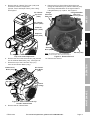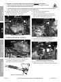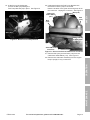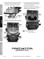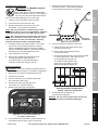
1
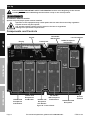
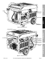
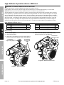
Owner’s Manual & Safety Instructions
Save This Manual Keep this manual for the safety warnings and precautions, assembly,
operating, inspection, maintenance and cleaning procedures. Write the product’s serial number in the
back of the manual near the assembly diagram (or month and year of purchase if product has no number).
Keep this manual and the receipt in a safe and dry place for future reference.
REV 15a
13,500 WATT
PORTABLE
GENERATOR
11,000 RUNNING WATTS
13,500 PEAK WATTS
Using a generator indoors CAN
KILL YOU IN MINUTES.
Generator exhaust contains
carbon monoxide. This is a poison
you cannot see or smell.
NEVER use inside
a home or garage,
EVEN IF doors and
windows are open.
Only use OUTSIDE
and far away from
windows, doors,
and vents.
ITEM 61725
Visit our website at: http://www.harborfreight.com
Email our technical support at: [email protected]
Email our engine support at: [email protected]
When unpacking, make sure that the product is intact
and undamaged. If any parts are missing or broken,
please call 1-888-866-5797 as soon as possible.
Copyright© 2013 by Harbor Freight Tools®. All rights reserved.
No portion of this manual or any artwork contained herein may be reproduced in
any shape or form without the express written consent of Harbor Freight Tools.
Diagrams within this manual may not be drawn proportionally. Due to continuing
improvements, actual product may differ slightly from the product described herein.
Tools required for assembly and service may not be included.
Read this material before using this product.
Failure to do so can result in serious injury.
SAVE THIS MANUAL.
Table of Contents
Specifications.............................................. 2
Safety��������������������������������������������������������� 3
Setup........................................................... 8
Operationr��������������������������������������������������� 16
Maintenances���������������������������������������������� 20
Troubleshooting.......................................... 24
Warranties.................................................. 26
Parts Lists and Diagrams........................... 28
Specifications
Generator
Output
120/240VAC, 60Hz, 1 Phase
11,000W Rated
13,500W Maximum
Receptacles
See Figure A: Control Panel on page 8
Displacement
Engine Type
Cooling System
Type
Fuel
Capacity
Type SAE
Engine Oil
Capacity
Run Time @ 50% Load
with full tank
Sound Level at 3 feet
Bore x Stroke
Compression Ratio
Rotation viewed from PTO
(power takeoff - the output shaft)
Spark Plug
Valve Clearance
Speed
670cc
Horizontal Dual Cylinder
4-stroke
Forced air cooled
87+ octane stabilizer treated
unleaded gasoline
7 Gallon
10W-30 above 32° F
5W30 at 32° F or below
SJ class oil
2 Quart
7.5 hr.
78 dB
78 mm x 70 mm
7.93:1
Counterclockwise
Type
NGK® BP-6ES
NHSP® / Torch® F6TC
Gap
Intake
Exhaust
Idle
0.7 - 0.8 mm
0.10 - 0.15 mm
0.15 - 0.20 mm
1800 RPM
The emissions control system for this Engine is warranted for standards set by the
U.S. Environmental Protection Agency. For warranty information, refer to the last pages of this manual.
Page 2
For technical questions, please call 1-888-866-5797.
ITEM 61725
WARNING SYMBOLS AND DEFINITIONS
This is the safety alert symbol. It is used to alert you to potential
personal injury hazards. Obey all safety messages that
follow this symbol to avoid possible injury or death.
Safety
Indicates a hazardous situation which, if not avoided,
will result in death or serious injury.
Indicates a hazardous situation which, if not avoided,
could result in death or serious injury.
Indicates a hazardous situation which, if not avoided,
could result in minor or moderate injury.
Addresses practices not related to personal injury.
RPM
HP
Property or Statement
Revolutions Per Minute
Horsepower
WARNING marking concerning
Risk of Eye Injury. Wear ANSI-approved
safety goggles with side shields.
Read the manual before
set-up and/or use.
WARNING marking concerning
Risk of Hearing Loss.
Wear hearing protection.
Symbol
Property or Statement
WARNING marking concerning
Risk of Respiratory Injury.
Operate engine OUTSIDE and far away
from windows, doors, and vents.
WARNING marking concerning
Risk of Fire while handling fuel.
Do not smoke while handling fuel.
WARNING marking concerning
Risk of Fire.
Do not refuel while operating.
Keep flammable objects
away from engine.
IMPORTANT SAFETY INSTRUCTIONS
Operation
Symbol
Setup
Symbol Definitions
WARNING! Read all instructions.
Failure to follow all instructions listed below may result in fire, serious injury and/or DEATH.
The warnings and precautions discussed in this manual cannot cover all possible conditions and
situations that may occur. It must be understood by the operator that common sense and caution
are factors which cannot be built into this product, but must be supplied by the operator.
ITEM 61725
For technical questions, please call 1-888-866-5797.
Maintenance
SAVE THESE INSTRUCTIONS
Page 3
Set up Precautions
1. Gasoline fuel and fumes are flammable, and
potentially explosive. Use proper fuel storage
and handling procedures. Do not store fuel
or other flammable materials nearby.
Safety
2. Have multiple ABC class fire extinguishers nearby.
3. Operation of this equipment may create sparks that
can start fires around dry vegetation.
A spark arrestor may be required. The operator
should contact local fire agencies for laws or
regulations relating to fire prevention requirements.
4. Set up and use only on a flat, level,
well‑ventilated surface.
5. All connections and conduits from the Generator
to the load must only be installed by trained and
licensed electricians, and in compliance with all
relevant local, state, and federal electrical codes and
standards, and other regulations where applicable.
6. Connections for standby power to a building
electrical system must be made by a qualified
electrician. The connection must isolate the
generator power from utility power, and must comply
with all applicable laws and electrical codes.
7. Wear ANSI-approved safety goggles, heavy-duty
work gloves, and dust mask/respirator during set up.
8. Use only lubricants and fuel recommended
in the Specifications chart of this manual.
9. Improper connections to a building electrical system
can allow electrical current from the generator
to backfeed into the utility lines. Such backfeed
may electrocute utility company workers or others
who contact the lines during a power outage,
and the generator may explode, burn, or cause
fires when utility power is restored. Consult
the utility company and a qualified electrician if
intending to use the generator for back up power.
Setup
10. Do not operate the Generator before grounding.
The Generator must be earth-grounded
in accordance with all relevant electrical
codes and standards before operation.
Operation
Maintenance
Page 4
For technical questions, please call 1-888-866-5797.
ITEM 61725
Operating Precautions
13. Avoid substantially overloading which will trip
the circuit breaker. Slightly overloading the
generator may not trip the circuit breaker,
but will lead to premature generator failure.
14. Do not attempt to connect or disconnect
load connections while standing in water,
or on wet or soggy ground.
2. Never use a generator indoors, including in
garages, basements, crawl spaces and sheds.
Opening doors and windows or using fans will NOT
prevent carbon monoxide build up in the home.
3. When using generators, keep them outdoors
and far away from open doors, windows,
and vents to avoid toxic levels of carbon
monoxide from building up indoors.
4. If you start to feel sick, dizzy, or weak while
using a generator, get to fresh air right away.
The carbon monoxide from generators can
quickly lead to full incapacitation and death.
5. Keep children away from the equipment,
especially while it is operating.
6. Keep all spectators at least six feet
from the Engine during operation.
7. Fire Hazard! Do not fill fuel tank while engine is
running. Do not operate if gasoline has been spilled.
Clean spilled gasoline before starting engine.
Do not operate near pilot light or open flame.
8. Do not touch engine during use.
Let engine cool down after use.
9. Never store fuel or other flammable
materials near the engine.
10. If the plugged in product operates abnormally
or unusually slow, immediately stop using the
generator as a power source. Read and adhere
to the instruction manual of the product to be
powered to make sure that it can be safely and
efficiently powered by a portable generator.
ITEM 61725
Setup
15. Do not touch electrically energized parts of
the Generator and interconnecting cables
or conductors with any part of the body, or
with any non-insulated conductive object.
Only use OUTSIDE and far away from windows,
doors, and vents.
Safety
12. Do not exceed the maximum power rating of the
generator. Make sure that the total electrical rating
of the all of the tools or appliances plugged into
the generator at the same time does not exceed
that of the generator. Check that the startup surge
will not be beyond the limit of the Generator.
16. Connect the Generator only to a load that is
compatible with the electrical characteristics
and rated capacities of the Generator.
17. Insulate all connections and disconnected wires.
18. Guard against electric shock. Prevent body contact
with grounded surfaces such as pipes,
radiators, ranges, and refrigerators.
19. Only use a suitable means of transport and
lifting devices with sufficient weight bearing
capacity when transporting the generator.
20. Secure the generator on transport vehicles to
prevent it from rolling, slipping, and tilting.
21. Industrial applications must follow
OSHA requirements.
22. Do not leave the generator unattended when it is
running. Turn off the generator (and remove safety
keys, if available) before leaving the work area.
Operation
NEVER use inside a home or garage,
EVEN IF doors and windows are open.
11. Before connecting an appliance or power cord
to the generator: Make sure that it is in good
working order. Faulty appliances or power cords
can create a potential for electrical shock.
23. The generator can produce high noise levels.
Prolonged exposure to noise levels
above 85 dBA is hazardous to hearing.
Wear ear protection when operating the generator
or when working nearby while it is operating.
24. Wear ANSI-approved safety glasses
and hearing protection during use.
25. People with pacemakers should consult their
physician(s) before use. Electromagnetic fields in
close proximity to a heart pacemaker could cause
pacemaker interference or pacemaker failure.
Caution is necessary when near the
engine’s magneto or recoil starter.
For technical questions, please call 1-888-866-5797.
Page 5
Maintenance
CARBON MONOXIDE HAZARD
Using a generator indoors
CAN KILL YOU IN MINUTES.
Generator exhaust contains
carbon monoxide. This is a poison
you cannot see or smell.
1.
Operating Precautions (cont.)
Safety
26. Use only accessories that are recommended
by Harbor Freight Tools for your model.
Accessories that may be suitable for one
piece of equipment may become hazardous
when used on another piece of equipment.
27. Do not operate in explosive atmospheres,
such as in the presence of flammable
liquids, gases, or dust. Gasoline-powered
engines may ignite the dust or fumes.
28. Stay alert, watch what you are doing and
use common sense when operating this
generator. Do not use while tired or under the
influence of drugs, alcohol or medication.
29. Dress properly. Do not wear loose clothing or
jewelry. Keep hair, clothing and gloves away
from moving parts. Loose clothes, jewelry or
long hair can be caught in moving parts.
Setup
30. Parts, especially exhaust system components,
get very hot during use. Stay clear of hot parts.
31. Do not cover the generator during operation.
32. Keep the generator and surrounding
area clean at all times.
33. Use the equipment, accessories, etc., in
accordance with these instructions and in the
manner intended for the particular type of
equipment, taking into account the working
conditions and the work to be performed.
Use of the equipment for operations different from
those intended could result in a hazardous situation.
34. Do not operate the equipment with known
leaks in the engine’s fuel system.
35. WARNING: This product contains or, when
used, produces a chemical known to the State
of California to cause cancer and birth defects
or other reproductive harm. (California Health
& Safety Code § 25249.5, et seq.)
36. When spills of fuel or oil occur, they must be
cleaned up immediately. Dispose of fluids and
cleaning materials as per any local, state, or
federal codes and regulations. Store oil rags in
a bottom-ventilated, covered, metal container.
37. Keep hands and feet away from moving parts.
Do not reach over or across
equipment while operating.
38. Before use, check for misalignment or binding of
moving parts, breakage of parts, and any other
condition that may affect the equipment’s operation.
If damaged, have the equipment serviced
before using. Many accidents are caused
by poorly maintained equipment.
39. Use the correct equipment for the application.
Do not modify the equipment and do not use the
equipment for a purpose for which it is not intended.
Operation
Maintenance
Page 6
For technical questions, please call 1-888-866-5797.
ITEM 61725
a. Unplug all devices from the generator.
b. Turn the engine switch to its “OFF” position.
c. Allow the engine to completely cool.
d. Then, remove the spark plug cap
from the spark plug.
2. Keep all safety guards in place and in
proper working order. Safety guards include
muffler, air cleaner, mechanical guards,
and heat shields, among other guards.
3. Keep all electrical equipment clean and dry.
Replace any wiring where the insulation is
cracked, cut, abraded, or otherwise degraded.
Replace terminals that are worn, discolored, or
corroded. Keep terminals clean and tight.
4. Do not alter or adjust any part of the
equipment or its engine that is sealed by the
manufacturer or distributor. Only a qualified
service technician may adjust parts that may
increase or decrease governed engine speed.
5. Wear ANSI-approved safety goggles,
heavy‑duty work gloves, and
dust mask/respirator during service.
6. Maintain labels and nameplates on the equipment.
These carry important information.
If unreadable or missing, contact
Harbor Freight Tools for a replacement.
7. Have the equipment serviced by a qualified repair
person using only identical replacement parts.
This will ensure that the safety of the equipment
is maintained. Do not attempt any service or
maintenance procedures not explained in this
manual or any procedures that you are uncertain
about your ability to perform safely or correctly.
8. Store equipment out of the reach of children.
9. Follow scheduled engine and
equipment maintenance.
Refueling:
1. Do not smoke, or allow sparks, flames,
or other sources of ignition around the
equipment, especially when refuelling.
2. Do not refill the fuel tank while the
engine is running or hot.
3. Do not fill fuel tank to the top.
Leave a little room for the fuel to expand as needed.
4. Refuel in a well-ventilated area only.
5. Wipe up any spilled fuel and allow excess
to evaporate before starting engine.
To prevent FIRE, do not start the engine
while the smell of fuel hangs in the air.
Maintenance
Operation
SAVE THESE INSTRUCTIONS.
Setup
1. Before service, maintenance, or cleaning:
Safety
Service Precautions
ITEM 61725
For technical questions, please call 1-888-866-5797.
Page 7
Set Up
Read the ENTIRE IMPORTANT SAFETY INFORMATION section at the beginning of this manual
including all text under subheadings therein before set up or use of this product.
Safety
TO PREVENT SERIOUS INJURY:
Operate only with proper spark arrestor installed.
Operation of this equipment may create sparks that can start fires around dry vegetation.
A spark arrestor may be required.
The operator should contact local fire agencies for laws or regulations
relating to fire prevention requirements.
Components and Controls
120/240VAC
46A Breakers
Switch
Setup
Display
Low Oil Indicator
12VDC Receptacle
and Breaker
Choke Knob
Operation
Maintenance
120VAC 20A
Receptacles
and Breaker
Page 8
120VAC 20A
Receptacles
and Breaker
120/240VAC
30A Receptacle
and Breakers
120VAC 30A
Receptacle
and Breaker
Figure A: Control Panel
Ground
Terminal
120/240VAC 46A
Receptacle
For technical questions, please call 1-888-866-5797.
ITEM 61725
Handle
Spark Plug
(1 of 2)
Safety
Fuel Cap
Battery
(sold separately)
Setup
Control Panel
Figure B: Generator Front
Air Cleaner
Fuel Valve
Operation
Lifting Bracket
Muffler
Oil Fill Plug
Dipstick
Maintenance
Spark Plug
(2 of 2)
Figure C: Generator Back
ITEM 61725
For technical questions, please call 1-888-866-5797.
Page 9
High Altitude Operation Above 3000 feet
WARNING! TO PREVENT SERIOUS INJURY FROM FIRE:
Follow instructions in a well-ventilated area away from ignition sources.
If the engine is hot from use, shut the engine off and wait for it to cool before proceeding. Do not smoke.
Safety
NOTICE: Warranty void if necessary adjustments are not made for high altitude use.
At high altitudes, the engine’s carburetor, governor, and any other parts that control the fuel-air ratio will need
to be adjusted by a qualified mechanic to allow efficient high-altitude use and to prevent damage to the engine
and any other devices used with this product. The fuel system on this engine may be influenced by operation
at higher altitudes. Proper operation can be ensured by installing an altitude kit at altitudes higher than 3000 ft.
above sea level. At elevations above 8000 ft, the engine may experience decreased performance, even with
the proper main jet. Operating this engine without the proper altitude kit installed may increase the engine’s
emissions and decrease fuel economy and performance. The kit should be installed by a qualified mechanic.
High Altitude Kit Parts List - A
Setup
Part
A1
A2
A3
Description
Left Main Jet 3000-6000 ft.
Right Main Jet 3000-6000 ft.
Left Main Jet 6000-8000 ft.
Qty
1
1
1
Part
Description
A4 Right Main Jet 6000-8000 ft.
137d Outer Bowl O-ring (replacement)
137e Inner Bowl O-ring (replacement)
Qty
1
1
1
Disassembly
1. Turn off the engine.
4. Remove the Air Cleaner Front Cover (101),
pulling it up then out. See Figure E.
2. Close the fuel valve.
Air Cleaner
Front Cover (101)
3. Remove the Air Cleaner Top Knob (142a) and the
two Air Cleaner Front Knobs (102). See Figure D.
Air Cleaner
Top Knob (142a)
Air Cleaner
Front Knob
(102)
Operation
Figure E: Remove Front Cover
Maintenance
Figure D: Remove Knobs
Page 10
For technical questions, please call 1-888-866-5797.
ITEM 61725
Air Cleaner
Top Cover
(142b)
9. Remove the four Shroud Nuts (99) and the two
Flange Shoulder Bolts (112) from the Shroud (100).
The Flange Shoulder Bolt on the right holds the
Lifting Bracket (111) in place. See Figure H.
Flange
Shoulder
Bolt (112)
Flange Shoulder
Bolt (112)
behind Lifting Bracket
Air Cleaner
Spacer (142c)
Safety
5. Remove the Air Cleaner Top Cover (142b) and
internal Air Cleaner components
(Spacer, Foam and Paper Filters (142c-142e)).
See Figure F.
Foam Air
Filter (142d)
Setup
Paper Air
Filter (142e)
Shroud
Nuts (99)
Figure F: Remove Air Cleaner
Top Cover and components
6. Remove the two Intake Cover Bolts (143) and the
two Air Cleaner Base Bolts (146). See Figure G.
Note: Air Cleaner Front Cover is still shown,
although it should have been removed in step 4.
Shroud (100)
Figure H: Remove Shroud
10. Remove the Shroud.
Intake Cover
Bolts (143)
Operation
7. Detach the top of the Fuel Filter Clip (147)
from the Air Cleaner Base (142g).
Air Cleaner
Base Bolts
(146)
Fuel Filter
Clip (147)
Maintenance
Air Cleaner
Base (142g)
Figure G: Remove Bolts and Clip
from Air Cleaner Base
8. Remove the Air Cleaner Base.
ITEM 61725
For technical questions, please call 1-888-866-5797.
Page 11
11. WARNING! TO PREVENT SERIOUS INJURY FROM FIRE, BEFORE CONTINUING:
a. Make sure that the work area is well‑ventilated and that there are no ignition sources.
b. Have multiple class ABC fire extinguishers available.
c. Double-check that fuel hose leading from fuel tank to Fuel Filter is clamped or fuel valve is closed.
Safety
d. Use a safe, proper means to clean up all fuel spills immediately.
12. Squeeze the Spring Clamp (140) and slide it back.
Detach the Fuel Hose (141) from the port at
the top of the Carburetor. See Figure I.
Spring
Clamp (140)
15. Disconnect the Throttle Rod Spring
from the Throttle Rod Clip.
16. Squeeze the Spring Wire Clamp (32) and slide
it back. Detach the Breather Hose (33) from the
right side of the Carburetor. See Figure L.
Spring Wire
Clamp (32)
Fuel
Hose (141)
fuel
port
Breather
Hose (33)
Setup
Figure I: Detach Fuel Hose
13. Locate the Throttle Rod (174) connection on
the left side of the carburetor. See Figure J.
Throttle
Rod (174)
Operation
Throttle Rod
Spring (175)
Figure L: Detach Breather Hose
17. Locate the Choke Rod (177) connection on the
right side of the carburetor. See Figure M.
Choke Rod
Clip (176)
Throttle Rod
Clip (139)
Choke
Rod (177)
Figure J: Disconnect Throttle Rod
Maintenance
14. A: Swing the black Throttle Rod Clip (139) down
to release the Throttle Rod. See Figure K.
B: Pull the Throttle Rod out of the Clip.
Figure M: Disconnect Choke Rod
18. Swing the black Choke Rod Clip (176) aside to
release the Choke Rod. Disconnect the Choke Rod.
B
A
Figure K: Throttle Rod Clip
Page 12
For technical questions, please call 1-888-866-5797.
ITEM 61725
20. Underneath where the Fuel Pump Bracket was,
the Solenoid Valve (138) is connected.
Note the location of the green wire and green dot on
the connector. Unplug the connector. See Figure O.
Carburetor
Intake Elbow
(131)
Fuel Pump
Bracket (40)
Bolt
(132)
Bolt (133)
Bolt
(132)
Safety
19. At the front of the Carburetor,
remove the Bolt (38) holding the
Fuel Pump Bracket (40) in place. See Figure N.
Bolt (38)
Figure N: Remove Fuel Pump Bracket
Solenoid wire
connector
Figure O: Disconnect Solenoid Valve wire connector
Setup
Note location
of dots here.
21. Remove Bolt (133) and two Bolts (132) from the
Carburetor Intake Elbow (131). See Figure O.
Maintenance
Operation
22. Remove the Carburetor assembly from the engine.
Keep it upright, it may contain fuel.
ITEM 61725
For technical questions, please call 1-888-866-5797.
Page 13
23. Hold the fuel drain port over a bowl, and open the
Carburetor Drain Plug (137a) to allow fuel to drain
out of that port. Once the carburetor is empty,
close the Carburetor Drain Plug. See Figure P.
26. Use a carburetor screwdriver (sold separately)
to remove the Left Main Jet and replace it with
the proper replacement Left Main Jet (A1 or A3)
for the altitude. See Figure R.
Safety
27. Use a carburetor screwdriver to remove the
Right Main Jet and replace it with the replacement
Right Main Jet (A2 or A4) for the same altitude
as the Left Main Jet. See Figure R.
fuel
drain
port
Carburetor
Drain Plug
(137a)
Right
Main Jet
(A2/A4)
Left
Main Jet
(A1/A3)
Figure P: Carburetor Drain
24. Turn the Carburetor assembly over.
Setup
25. Remove the four Carburetor Bowl Bolts (137b) and
remove the Carburetor Bowl (137c). See Figure Q.
Carburetor
Bowl Bolt
(137b)
Carburetor
Bowl Bolt
(137b)
Operation
Note: Since carburetor is upside-down,
left and right sides are reversed.
Figure R: Main Jets
Carburetor
Bowl
(137c)
Carburetor
Bowl Bolt
(137b)
Carburetor
Bowl Bolt
(137b)
Figure Q: Carburetor Bowl Bolts
Maintenance
Page 14
For technical questions, please call 1-888-866-5797.
ITEM 61725
Reassembly
1. Replace the Outer and Inner Bowl O-rings
(137d, 137e) with the replacements
from the altitude kit. Do not reuse existing O-rings.
5. Attach the Choke Rod on the right side of the
Carburetor, and secure it with its Clip. [#17,18]
6. Attach the Breather Hose to the Carburetor,
and secure it with its Clamp. [#16]
7. Attach the Throttle Rod Spring to the Throttle Rod
Clip on the left side of the Carburetor. [#15]
Inner Bowl
O-ring
8. Insert the Throttle Rod on the left side of the
Carburetor, and secure it with its Clip. [#14]
Safety
Note: Reassembly step references shown in brackets.
9. Attach the Fuel Hose to the port at the top of the
Carburetor and attach it using its Clamp. [#12]
Outer Bowl
O-ring
10. Install Shroud using four Shroud Bolts and two
Flange Shoulder Bolts. [#9,10] Include the Lifting
Bracket in place on the right Flange Shoulder Bolt.
2. Assemble the Carburetor Bowl using four
Carburetor Bowl Bolts. [#25] Assemble Carburetor
Intake Elbow to Intake using Bolts. [#21]
3. Attach Solenoid Valve connector, line up green
wire with the green dot on the connector. [#20]
4. Attach Fuel Pump Bracket to front of intake
using Bolt. Gently lift the Bracket after
assembly to ensure proper alignment. [#19]
13. Replace the Air Cleaner Front Cover. [#4]
14. Use the Air Cleaner Top Knob and Air Cleaner
Front Knobs to secure the Covers in place. [#3]
15. Once all connections are secure, open fuel valve.
16. Wipe up any spilled fuel and allow excess
to evaporate before starting engine.
To prevent FIRE, do not start the engine
while the smell of fuel hangs in the air.
Operation
Figure S: Replace Bowl O-rings
12. Place the Paper Air Filter, Foam Air Filter,
Air Cleaner Spacer, and Air Cleaner Top Cover
into place on the Air Cleaner Base. [#5]
Battery Setup Instructions
1. Place a fully charged, lead-acid 12 volt,
36 Ah battery (not included) in a stable,
flat location near the engine.
4. Attach the negative cable securely to
the negative battery terminal to prevent
disconnection and short circuits.
2. Use provided battery cables only.
5. Coat the terminals and cable ends with
a corrosion-preventive coating.
3. Attach the positive cable securely to
the positive battery terminal to prevent
disconnection and short circuits.
Grounding
1. The Generator must be properly grounded
in accordance with all relevant electrical
codes and standards before operation.
Have the unit grounded by a qualified electrician
if you are not qualified to do so.
2. To ground the Generator, connect a #XX AWG
grounding wire (not included) from the
Grounding Terminal on the Control Panel
to a grounding rod (not included).
The grounding rod must be an earth-driven
copper or brass rod (electrode) which can
adequately ground the Generator.
3. Refer to local regulations for
ground source information.
ITEM 61725
For technical questions, please call 1-888-866-5797.
Page 15
Maintenance
Carburetor
Bowl
Setup
11. Install Air Cleaner Base using two Air Cleaner Base
Bolts. Connect Fuel Filter Clip under left side of
Air Cleaner Base. Install the Intake Cover and
Intake Screen using the Intake Cover Bolts. [#6-8]
Operation
Read the ENTIRE IMPORTANT SAFETY INFORMATION section at the beginning of this manual
including all text under subheadings therein before set up or use of this product.
Safety
Pre-Start Checks
Inspect engine and equipment looking for damaged, loose, and missing parts before set up and starting.
If any problems are found, do not use equipment until fixed properly.
Checking and Filling Engine Oil
Setup
NOTICE: Your Warranty is VOID if the engine’s
crankcase is not properly filled with oil before
each use. Before each use, check the oil level.
Do not run the engine with low or no engine oil.
Running the engine with no or low engine oil
WILL permanently damage the engine.
Oil Fill Cap
(yellow)
Dipstick
1. Make sure the engine is stopped and is level.
2. Close the Fuel Valve.
3. On the back of the Generator, pull the Dipstick out,
and wipe its end off with a clean, lint free rag.
4. Reinsert the Dipstick fully and remove it to
check the oil level. The oil level should be
up to the full level as shown in Figure U.
5. If the oil level is at or below the low mark:
Operation
a. Clean the top of the yellow Oil Fill Cap
and the area around it.
Figure T: Oil Fill Cap and Dipstick
(on back of Generator)
b. Remove the Oil Fill Cap by turning
it counterclockwise.
c. Add the appropriate type of oil until the oil level
is at the proper level. SAE 10W‑30 oil is
recommended for general use.
(Table A: SAE Viscosity Grades on page 21 in
the Maintenance section shows other viscosities
to use in different average temperatures.)
Dipstick
6. Thread the Oil Fill Cap back in
and reinsert the Dipstick.
NOTICE: Do not run the engine with too little oil.
The engine will be permanently damaged.
Full Level
Maintenance
Figure U: Oil Fill Level
Page 16
For technical questions, please call 1-888-866-5797.
Engine
Crankcase
ITEM 61725
WARNING! TO PREVENT SERIOUS
INJURY FROM FIRE:
Fill the fuel tank in a well-ventilated area
away from ignition sources. If the engine is
hot from use, shut the engine off and wait
for it to cool before adding fuel.
Do not smoke.
1. Clean the Fuel Cap and the area around it.
2. Unscrew and remove the Fuel Cap.
Note: Do not use gasoline that has been stored in a
metal fuel container or a dirty fuel container. It can
cause particles to enter the carburetor, effecting
engine performance and/or causing damage.
4. Then replace the Fuel Cap.
5. Wipe up any spilled fuel and allow excess
to evaporate before starting engine.
To prevent FIRE, do not start the engine
while the smell of fuel hangs in the air.
Maintenance
Operation
Setup
3. If needed, fill the Fuel Tank to about 1 inch under
the fill neck of the Fuel Tank with 87 octane or
higher unleaded gasoline that has been treated
with a fuel stabilizer additive. Follow fuel stabilizer
manufacturer’s recommendations for use.
Note: Do not use gasoline containing more than
10% ethanol (E10). Do not use E85 ethanol.
Safety
Checking and Filling Fuel
ITEM 61725
For technical questions, please call 1-888-866-5797.
Page 17
Starting the Engine
Safety
Before starting the engine:
a. Inspect the generator and engine.
b. Disconnect all electrical loads from the generator.
c. Fill the engine with the proper amount and type of both unleaded gasoline and oil.
1. To start a cold engine, pull the START Knob out
to the START position.
To restart a warm engine, push the START Knob in
to the RUN position.
1
Setup
2. Open the Fuel Valve.
2
OFF
ON
ON
3. Turn the Engine Switch to START.
OFF
START
Operation
4. Allow the Engine to run for several seconds.
Then, if the START lever is in the START position,
move the START Lever very slowly to its RUN position.
Note: Moving the START Lever too
fast could stall the engine.
3
4
Maintenance
IMPORTANT: Allow the engine to run at no load for five minutes with no
load after each start‑up so that the engine can stabilize.
5. Adjust the Throttle as needed.
Break-in Period:
a. Breaking-in the engine will help to ensure proper equipment and engine operation.
b. The break‑in period will last about 25 hours of use. DO NOT exceed
75% of the Generator’s rated capacity during this period.
• Change the engine oil after this period.
Under normal operating conditions subsequent maintenance follows
the schedule explained in the Maintenance section.
Page 18
For technical questions, please call 1-888-866-5797.
ITEM 61725
Wattage Estimates
1. The total combined load through the outlet
on the Generator must not exceed the
rated maximum power of the unit.
Wattages listed below are estimates for that
type of equipment only. Check nameplate wattages
on all loads before connecting to Generator.
This Unit Can Power Any
Running Start-up
2. Reduce the load if the AC Circuit Breaker turns off.
One of the Following Items:
Watts
Watts
Once the load is reduced, press the Circuit Breaker
600
900
Button to reset the Generator and continue operation. 1/4 HP Air Compressor
1/6 HP Motor
500
800
3/8"
Drill
400
600
Calculate Power Draw:
Mini Refrigerator
400
700
Table/Box
Fan
200
Power draw can be calculated by multiplying volts
15 Amp Battery Charger
380
and amps. The resulting number is wattage.
String Trimmer
350
• Never exceed the rated maximum wattage for
Hedge Trimmer
500
the Generator or any outlet amperage rating.
Radio
50
Ten 75 Watt Light Bulbs
750
• Refer to appliance/tool owner’s manuals to
determine the wattage of electrical load devices.
3. Allow the Engine to run at no load for five minutes
• Long power cords and extension cords draw
after each start‑up to allow the Engine to stabilize.
additional power. Keep cord length at a minimum.
Setup
Load and Circuit Breaker:
Safety
Connecting Loads to the Generator
Figure V: Plug Load In
4. Plug the power cord of the 120 volt appliance/
tool into the 120 volt AC Outlet on the Generator.
Note: Do not allow the generator to completely run out of fuel with devices attached.
A generator’s output may sharply spike as it runs out of fuel, causing damage to attached devices.
Operation
Stopping the Engine
1. To stop the engine in an emergency,
turn the Engine Switch off.
2. Under normal conditions, use the following procedure:
Maintenance
a. Remove all electrical load devices
from the Generator.
b. Turn the Engine Switch off.
c. Close the Fuel Valve.
NOTICE
See Long-Term Storage on page 23
for complete storage instructions.
ITEM 61725
For technical questions, please call 1-888-866-5797.
Page 19
Maintenance
WARNING
Safety
TO PREVENT SERIOUS INJURY FROM ACCIDENTAL STARTING:
Turn the Power Switch of the equipment to its “OFF” position, wait for the engine to cool, and disconnect
the spark plug cap before performing any inspection, maintenance, or cleaning procedures.
TO PREVENT SERIOUS INJURY FROM EQUIPMENT FAILURE:
Do not use damaged equipment. If abnormal noise, vibration, or excess
smoking occurs, have the problem corrected before further use.
Follow all service instructions in this manual. The engine may fail critically if not serviced properly.
Many maintenance procedures, including any not detailed in this manual, will need to be performed
by a qualified technician for safety. If you have any doubts about your ability to safely service the
equipment or engine, have a qualified technician service the equipment instead.
Cleaning, Maintenance, and Lubrication Schedule
Setup
Note: This maintenance schedule is intended solely as a general guide. If performance decreases or if
equipment operates unusually, check systems immediately. The maintenance needs of each piece of equipment
will differ depending on factors such as duty cycle, temperature, air quality, fuel quality, and other factors.
Note: The following procedures are in addition to the regular checks and maintenance
explained as part of the regular operation of the engine and equipment.
Before
Each Use
Procedure
Monthly or
Every 3 mo. or Every 6 mo. or
every 20
50 hr. of use 100 hr. of use
hr. of use
Yearly or
every 300
hr. of use
Every
2 Years
Brush off outside of engine
Check engine oil level
Check air cleaner
Check sediment cup
Change engine oil
Operation
*
Clean air filter
Check and clean spark plug
1. Check/adjust idle speed
2. Check/adjust valve clearance
3. Clean fuel tank, strainer
and carburetor
**
4. Clean carbon build-up from
combustion chamber
Replace fuel line if necessary
**
**
*Service more frequently when used in dusty areas.
**These items should be serviced by a qualified technician.
Maintenance
Page 20
For technical questions, please call 1-888-866-5797.
ITEM 61725
WARNING! TO PREVENT SERIOUS
INJURY FROM FIRE:
Fill the fuel tank in a well-ventilated area
away from ignition sources. If the engine is
hot from use, shut the engine off and wait
for it to cool before adding fuel. Do not smoke.
7. Reinsert the Dipstick fully and remove it to
check the oil level. The oil level should be
up to the full level as shown in Figure X.
Dipstick
1. Clean the Fuel Cap and the area around it.
2. Unscrew and remove the Fuel Cap.
3. Remove the Strainer and remove any dirt
and debris. Then replace the Strainer.
Note: Do not use gasoline that has been stored in a
metal fuel container or a dirty fuel container. It can
cause particles to enter the carburetor, affecting
engine performance and/or causing damage.
Full Level
4. If needed, fill the Fuel Tank to about 1 inch under
the fill neck of the Fuel Tank with 87 octane or
higher unleaded gasoline that has been treated
with a fuel stabilizer additive. Follow fuel stabilizer
manufacturer’s recommendations for use.
8. If the oil level is at or below the low mark:
5. Then replace the Fuel Cap.
6. Wipe up any spilled fuel and allow excess
to evaporate before starting engine.
To prevent FIRE, do not start the engine
while the smell of fuel hangs in the air.
Engine Oil Change
Setup
Figure X: Oil Fill Level
Engine
Crankcase
a. Clean the top of the yellow Oil Fill Cap
and the area around it.
b. Remove the Oil Fill Cap by turning
it counterclockwise.
c. Add the appropriate type of oil until the oil level
is at the proper level. SAE 10W‑30 oil is
recommended for general use.
The SAE Viscosity Grade chart
shows other viscosities to use in
different average temperatures.
CAUTION! Oil is very hot during operation and can
cause burns. Wait for engine to cool before changing oil.
30
Operation
Note: Do not use gasoline containing more than
10% ethanol (E10). Do not use E85 ethanol. Add fuel
stabilizer to the gasoline or the Warranty is VOID.
1. Make sure the engine is stopped and is level.
2. Close the Fuel Valve.
10W-30
3. Place a drain pan (not included) underneath
the crankcase’s drain plug.
4. Remove the drain plug and allow the
oil to drain out. Recycle used oil.
5. Replace the drain plug and tighten it.
Safety
Checking and Filling Fuel
5W-30
-20
0
20
40
60
80
Average outdoor temperature
100°F
Table A: SAE Viscosity Grades
Dipstick
9. Thread the Oil Fill Cap back in
and reinsert the Dipstick.
NOTICE: Do not run the engine with too little oil.
The engine will be permanently damaged.
Figure W: Oil Fill Cap and Dipstick
(on back of Generator)
6. On the back of the Generator, pull the Dipstick out,
and wipe its end off with a clean, lint free rag.
ITEM 61725
For technical questions, please call 1-888-866-5797.
Page 21
Maintenance
Oil Fill Cap
(yellow)
Air Filter Maintenance
Spark plug Maintenance
1. Remove the Air Cleaner Cover and the air filters
and check for dirt. Clean as described below.
1. Disconnect spark plug caps from end of plugs.
Clean out debris from around spark plugs.
2. Cleaning:
2. Using a spark plug wrench, remove the spark plugs.
Safety
• For paper filters:
To prevent injury from dust and debris,
wear ANSI-approved safety goggles,
NIOSH‑approved dust mask/respirator, and
heavy-duty work gloves. In a well‑ventilated
area away from bystanders, use pressurized
air to blow dust out of the filter.
• For foam filters:
Wash the filter in warm water and mild
detergent several times. Rinse. Squeeze out
excess water and allow it to dry completely.
Soak the filter in lightweight oil briefly,
then squeeze out the excess oil.
3. Install the cleaned filters. Secure the
Air Cleaner Cover before use.
3. Inspect the spark plugs:
If the electrode is oily, clean it using a clean, dry rag.
If the electrode has deposits on it, polish it using
emery paper. If the white insulator is cracked or
chipped, the spark plug needs to be replaced.
Recommended Spark Plugs
NGK®
NHSP® / TORCH®
BP-6ES
F6TC
NOTICE: Using an incorrect spark plug
may damage the engine.
Setup
4. When installing a new spark plug,
adjust the plug’s gap to the specification on the
Specifications chart. Do not pry against the
electrode, the spark plug can be damaged.
5. Install the new spark plugs or
the cleaned spark plugs into the engine.
• Gasket-style:
Finger-tighten until the gasket
contacts the cylinder head,
then tighten about 1/2-2/3 turn more.
• Non-gasket-style:
Finger-tighten until the plug
contacts the cylinder head,
then tighten about 1/16 turn more.
Operation
NOTICE: Tighten the spark plugs properly.
If loose, the spark plugs will cause the
engine to overheat.
If overtightened, the threads in the
engine block will be damaged.
6. Apply dielectric spark plug boot protector
(not included) to the end of the spark plugs
and reattach the wires securely.
Maintenance
Page 22
For technical questions, please call 1-888-866-5797.
ITEM 61725
When the equipment is to remain idle for longer than
20 days, prepare the engine for storage as follows:
c. Replace spark plug, but leave
spark plug cap disconnected.
1. CLEANING:
Wait for engine to cool, then clean engine with
dry cloth. NOTICE: Do not clean using water.
The water will gradually enter the engine
and cause rust damage. Apply a thin coat
of rust preventive oil to all metal parts.
d. Pull Starter Handle to distribute oil in cylinder.
Stop after one or two revolutions when you
feel the piston start the compression stroke
(when you start to feel resistance).
To protect the fuel tank during storage, fill the
tank with gasoline that has been treated with
a fuel stabilizer additive. Follow fuel stabilizer
manufacturer’s recommendations for use. Refer
to Checking and Filling Fuel on page 23.
WARNING! TO PREVENT SERIOUS
INJURY FROM FIRE:
Fill tank in a well-ventilated area away from
ignition sources. If the engine is hot from
use, shut the engine off and wait for it to
cool before adding fuel. Do not smoke.
3. LUBRICATION:
a. Change engine oil.
NOTICE: During extended storage periods the
Engine must be started every 3 months and allowed
to run for 15 – 20 minutes or the Warranty is VOID.
6. AFTER STORAGE:
Before starting the engine during or after
storage, keep in mind that untreated gasoline
will deteriorate quickly. Drain the fuel
tank and change to fresh fuel if untreated
gasoline has been sitting for a month, if
treated gasoline has been sitting beyond the
fuel stabilizer’s recommended time period,
or if the engine does not start.
Maintenance
Operation
b. Clean out area around spark plug.
Remove spark plug and pour one tablespoon of
engine oil into cylinder through spark plug hole.
5. STORAGE AREA:
Cover and store in a dry, level, well-ventilated
area out of reach of children. Storage area should
also be away from ignition sources, such as
water heaters, clothes dryers, and furnaces.
Setup
2. FUEL:
4. BATTERY:
Disconnect battery cables (if equipped).
Recharge batteries monthly while in storage.
Safety
Long-Term Storage
ITEM 61725
For technical questions, please call 1-888-866-5797.
Page 23
Troubleshooting
Problem
Possible Causes
Engine will not start FUEL RELATED:
Probable Solutions
FUEL RELATED:
Safety
Setup
Operation
Maintenance
1. No fuel in tank or fuel valve closed.
1. Fill fuel tank with fresh 87+ octane
stabilizer-treated unleaded gasoline and
open fuel valve.
Do not use gasoline with more than
10% ethanol (E15, E20, E85, etc.).
2. START not in START position, cold engine.
2. Move START to START position.
3. Gasoline with more than 10% ethanol used.
(E15, E20, E85, etc.)
3. Clean out ethanol rich gasoline from fuel
system. Replace components damaged by
ethanol. Use fresh 87+ octane stabilizertreated unleaded gasoline only.
Do not use gasoline with more than
10% ethanol (E15, E20, E85, etc.).
4. Low quality or deteriorated, old gasoline.
4. Use fresh 87+ octane stabilizer-treated
unleaded gasoline.
Do not use gasoline with more than
10% ethanol (E15, E20, E85, etc.).
5. Carburetor not primed.
5. Pull on Starter Handle to prime.
6. Dirty fuel passageways.
6. Clean out passageways using
fuel additive. Heavy deposits
may require further cleaning.
7. Carburetor needle stuck.
Fuel can be smelled in the air.
7. Gently tap side of carburetor float
chamber with screwdriver handle.
8. Too much fuel in chamber. This can be
caused by the carburetor needle sticking.
8. Turn START to RUN position.
Remove spark plug and pull the start
handle several times to air out the
chamber. Reinstall spark plug and
set START to START position.
9. Clogged Fuel Filter.
9. Replace Fuel Filter.
IGNITION (SPARK) RELATED:
IGNITION (SPARK) RELATED:
1. Spark plug cap not connected securely.
1. Connect spark plug cap properly.
2. Spark plug electrode wet or dirty.
2. Clean spark plug.
3. Incorrect spark plug gap.
3. Correct spark plug gap.
4. Spark plug cap broken.
4. Replace spark plug cap.
5. Circuit breaker tripped.
5. Reset circuit breaker. Check wiring and
starter motor if breaker continues to trip.
6. Incorrect spark timing or
faulty ignition system.
6. Have qualified technician diagnose/
repair ignition system.
COMPRESSION RELATED:
COMPRESSION RELATED:
1. Cylinder not lubricated.
Problem after long storage periods.
1. Pour tablespoon of oil into
spark plug hole. Crank engine a
few times and try to start again.
2. Loose or broken spark plug.
(Hissing noise will occur
when trying to start.)
2. Tighten spark plug.
If that does not work, replace spark plug.
If problem persists, may have
head gasket problem, see #3.
3. Loose cylinder head or damaged
head gasket. (Hissing noise will
occur when trying to start.)
3. Tighten head.
If that does not remedy problem,
replace head gasket.
4. Engine valves or tappets
mis‑adjusted or stuck.
4. Have qualified technician adjust/
repair valves and tappets.
Follow all safety precautions whenever diagnosing or servicing the generator or engine.
Page 24
For technical questions, please call 1-888-866-5797.
ITEM 61725
1. Check wire connections.
2. Incorrect spark plug gap or
damaged spark plug.
2. Re-gap or replace spark plug.
3. Defective spark plug cap.
3. Replace spark plug cap.
4. Old or low quality gasoline.
4. Use only fresh 87+ octane stabilizer-treated
unleaded gasoline.
Do not use gasoline with more than
10% ethanol (E15, E20, E85, etc.).
5. Incorrect compression.
5. Diagnose and repair compression.
(Use Engine will not start:
COMPRESSION RELATED section.)
1. Fuel tank empty or full of impure or low
quality gasoline.
1. Fill fuel tank with fresh 87+ octane
stabilizer-treated unleaded gasoline.
Do not use gasoline with more than
10% ethanol (E15, E20, E85, etc.).
2. Low oil shutdown.
2. Fill engine oil to proper level.
Check engine oil before EVERY use.
3. Defective fuel tank cap creating vacuum,
preventing proper fuel flow.
3. Test/replace fuel tank cap.
4. Faulty magneto.
4. Have qualified technician service magneto.
5. Disconnected or improperly
connected spark plug cap.
5. Secure spark plug cap.
Engine stops when
under heavy load
1. Dirty air filter
1. Clean element.
2. Engine running cold.
2. Allow engine to warm up prior
to operating equipment.
Engine knocks
1. Old or low quality gasoline.
1. Fill fuel tank with fresh 87+ octane
stabilizer-treated unleaded gasoline.
Do not use gasoline with more than
10% ethanol (E15, E20, E85, etc.).
2. Engine overloaded.
2. Do not exceed equipment’s load rating.
3. Incorrect spark timing, deposit buildup,
worn engine, or other mechanical problems.
3. Have qualified technician
diagnose and service engine.
1. Impure or low quality gasoline.
1. Fill fuel tank with fresh 87+ octane
stabilizer-treated unleaded gasoline.
Do not use gasoline with more than
10% ethanol (E15, E20, E85, etc.).
2. Engine too cold.
2. Use cold weather fuel and
oil additives to prevent backfiring.
3. Intake valve stuck or overheated engine.
3. Have qualified technician
diagnose and service engine.
4. Incorrect timing.
4. Check engine timing.
Engine stops
suddenly
Engine backfires
1. Device not plugged in properly.
Attached device
doesn’t have power
Attached device
begins to operate
abnormally
1. Turn off and unplug the device,
then plug it back in again and turn on.
2. Circuit Breaker tripped.
2. Turn off and unplug device, reset Circuit
Breaker, plug in device and turn on.
3. Product needs service.
3. Have product repaired.
1. Problem with device.
1. Immediately unplug device.
Have device repaired by a qualified
technician, or replace device.
2. Rated load capacity exceeded.
2. Lower the number of items plugged into
the generator to stay within the rated
capacity, or use a more powerful generator.
Follow all safety precautions whenever diagnosing or servicing the generator or engine.
ITEM 61725
Setup
1. Spark plug cap loose.
Safety
Probable Solutions
Operation
Engine misfires
Possible Causes
For technical questions, please call 1-888-866-5797.
Page 25
Maintenance
Problem
Warranties
Safety
Limited 90 Day Warranty
Harbor Freight Tools Co. makes every effort to assure that its products meet high quality and durability standards,
and warrants to the original purchaser that this product is free from defects in materials and workmanship for the
period of 90 days from the date of purchase. This warranty does not apply to damage due directly or indirectly,
to misuse, abuse, negligence or accidents, repairs or alterations outside our facilities, criminal activity, improper
installation, normal wear and tear, or to lack of maintenance. We shall in no event be liable for death, injuries
to persons or property, or for incidental, contingent, special or consequential damages arising from the use of
our product. Some states do not allow the exclusion or limitation of incidental or consequential damages, so the
above limitation of exclusion may not apply to you. THIS WARRANTY IS EXPRESSLY IN LIEU OF ALL OTHER
WARRANTIES, EXPRESS OR IMPLIED, INCLUDING THE WARRANTIES OF MERCHANTABILITY AND FITNESS.
Setup
To take advantage of this warranty, the product or part must be returned to us with transportation charges prepaid.
Proof of purchase date and an explanation of the complaint must accompany the merchandise.
If our inspection verifies the defect, we will either repair or replace the product at our election or
we may elect to refund the purchase price if we cannot readily and quickly provide you with a replacement.
We will return repaired products at our expense, but if we determine there is no defect, or that the defect resulted
from causes not within the scope of our warranty, then you must bear the cost of returning the product.
This warranty gives you specific legal rights and you may also have other rights which vary from state to state.
Emissions Control System Warranty
Operation
United States Emissions Control
Defects Warranty Statement
Harbor Freight Tools Emissions Control
Defects Warranty Coverage
The United States Environmental Protection Agency (herein EPA)
and Harbor Freight Tools (herein HFT) are pleased to explain the
emissions control system warranty on your 2014-2015 Small Off‑Road
Engine (herein engine). Within the United States, new off‑road,
spark-ignition engines certified for model year 2014-2015,
must meet similar standards set forth by the EPA. HFT must
warrant the emissions control system on your engine for the
periods of time described below, provided there has been no
abuse, neglect or improper maintenance of your engine.
Engines are warranted for a period of two (2) years relative
to emissions control parts defects, subject to the provisions
set forth below. If any emissions related part on your engine
is defective, the part will be repaired or replaced by HFT.
Your emissions control system may include parts such as the
carburetor or fuel-injection system, and the ignition system.
Also included may be hoses, belts, connectors
and other emissions‑related assemblies.
Where a warrantable condition exists, HFT will repair your
engine at no cost to you including diagnosis, parts and labor.
Manufacturer’s Warranty Coverage
Maintenance
The 2014-2015 engines are warranted for two (2) years.
If any emissions-related part on your engine is defective,
the part will be repaired or replaced by HFT.
Owner’s Warranty Responsibilities
• As the engine owner, you are responsible for the performance
of the required maintenance listed in your Owner’s Manual.
HFT recommends that you retain all receipts covering
maintenance on your engine, but HFT cannot deny warranty
solely for the lack of receipts or for your failure to
ensure the performance of all scheduled maintenance.
• As the engine owner, you should, however, be aware
that HFT may deny you warranty coverage if your
engine or a part has failed due to abuse, neglect,
improper maintenance, or unapproved modifications.
• You are responsible for shipping your engine to a HFT
warranty station as soon as a problem exists. Contact the
HFT Customer Service department at the number below to
make shipping arrangements. The warranty repairs should be
completed in a reasonable amount of time, not to exceed 30 days.
If you have any questions regarding your warranty rights
and responsibilities, you should contact the Harbor Freight Tools
Customer Service Department at 1-888-866-5797.
Page 26
For technical questions, please call 1-888-866-5797.
ITEM 61725
HFT warrants to a first retail purchaser and each
subsequent purchaser that the engine is free from
defects in materials and workmanship that cause
the failure of warranted parts for a period of two (2) years
after the date of delivery to the first retail purchaser.
2. No Charge Repair or Replacement
Repair or replacement of any warranted part will be
performed at no charge to the owner if the work is
performed through a warranty station authorized by HFT.
For emissions warranty service, contact the HFT
Customer Service Department at 1-888-866-5797.
Component parts which are not scheduled for replacement
as required maintenance or are scheduled only for regular
inspection to the effect of “repair or replace as necessary”
are warranted for the warranty period. Any warranted part
which is scheduled for replacement as required maintenance
is warranted for the period of time up to the first scheduled
replacement point for that part. Any replacement part, provided
it is equivalent in durability and performance, may be used
in performance of maintenance or repairs. The owner is
responsible for commissioning a qualified technician/mechanic
to perform all required maintenance, as outlined in the
Inspection, Cleaning, and Maintenance section in this manual.
6. Warranted Parts
1)
3. Consequential Damages Coverage
Coverage under this warranty shall also extend to the failure
of any engine components caused by the failure of any
warranted part while it is still covered under this warranty.
2)
4. Coverage Exclusions
3)
4)
5)
Operation
Warranty claims shall be filed in accordance with the provisions
of the HFT warranty policy explained in the box at the top of the
previous page. HFT shall not be liable for any loss of use of
the engine, for any alternative usage, for any damage to goods,
loss of time, or inconvenience. Warranty coverage shall also be
excluded for any part which fails, malfunctions, or is damaged
due to failure to follow the maintenance and operating instructions
set forth in the Owner’s Manual including, but not limited to:
a) Use of parts which are not authorized by HFT
b) Improper installation, adjustment or repair of
the engine or of any warranted part unless
performed by an authorized warranty center
c) Failure to follow recommendations on fuel use
contained in the Owner’s Manual
d) Improper or inadequate maintenance of any warranted parts
e) Repairs performed outside of
the authorized warranty service dealers
f) Alterations by changing, adding to or
removing parts from the engine.
Fuel Metering System
i) Carburetor and its internal parts.
ii) Fuel pump (if so equipped).
iii) Cold start enrichment system.
Air Induction System
i) Intake pipe/manifold.
ii) Air cleaner.
Ignition System
i) Spark plug.
ii) Magneto ignition system.
Catalyst System (if so equipped)
i) Exhaust pipe stud.
ii) Muffler.
iii) Catalytic converter (if so equipped).
Miscellaneous Items Used in Above Systems
i) Vacuum, temperature and time
sensitive valves and switches.
ii) Hoses, belts, connectors, and assemblies.
Safety
1. Length of Coverage
5. Service and Maintenance
Setup
Harbor Freight Tools Emissions Control
Defects Warranty Provisions
THE MANUFACTURER AND/OR DISTRIBUTOR HAS PROVIDED THE PARTS LIST AND ASSEMBLY DIAGRAM
IN THIS MANUAL AS A REFERENCE TOOL ONLY. NEITHER THE MANUFACTURER OR DISTRIBUTOR
MAKES ANY REPRESENTATION OR WARRANTY OF ANY KIND TO THE BUYER THAT HE OR SHE IS
QUALIFIED TO MAKE ANY REPAIRS TO THE PRODUCT, OR THAT HE OR SHE IS QUALIFIED TO REPLACE
ANY PARTS OF THE PRODUCT. IN FACT, THE MANUFACTURER AND/OR DISTRIBUTOR EXPRESSLY
STATES THAT ALL REPAIRS AND PARTS REPLACEMENTS SHOULD BE UNDERTAKEN BY CERTIFIED AND
LICENSED TECHNICIANS, AND NOT BY THE BUYER. THE BUYER ASSUMES ALL RISK AND LIABILITY
ARISING OUT OF HIS OR HER REPAIRS TO THE ORIGINAL PRODUCT OR REPLACEMENT PARTS
THERETO, OR ARISING OUT OF HIS OR HER INSTALLATION OF REPLACEMENT PARTS THERETO.
Record Product’s Serial Number Here:
Note: If product has no serial number, record
month and year of purchase instead.
ITEM 61725
Note: Some parts are listed and shown for
illustration purposes only, and are not available
individually as replacement parts.
For technical questions, please call 1-888-866-5797.
Page 27
Maintenance
PLEASE READ THE FOLLOWING CAREFULLY
Parts Lists and Diagrams
Parts List
Safety
Part
Setup
Operation
Maintenance
1
2
3
4
5
6
7
8
9
10
11
12
13
14
15
16
17
18
19
20
21
22
23
24
25
26
27
28
29
30
31
32
33
34
35
36
37
38
39
40
41
42
43
44
45
46
47
48
49
50
51
52
53
54
55
56
57
58
59
60
61
62
63
64
65
66
67
68
Page 28
Description
Cylinder Head Cover Bolt
Cover, Cylinder Head
Gasket, Cylinder Head Cover
Plug, Spark
Bolt, Cylinder Head
Cylinder Head
Right Cylinder Head
Pin
Gasket, Cylinder Head
Cross-Band Veneer
Stud
Stud
Cover, Cylinder Head
Plug , Engine Oil
Ring, Seal
Crankcase
Pin
Washer, Flat
Arm, Governor
Seal, Oil
Bolt, Drain Plug
Washer, Flat
Seal, Oil
Strainer, Breath Groove
Piece, Breath
Gasket, Breath Groove
Gasket, Breath Groove
Plate, Breath Groove Cover
Clamp
Bolt
Bolt
Clamp
Tube, Breather
Gasket, Inlet
Tube, Intake
Nut
Pump Asm, Gasoline
Bolt
Sleeve, Gasoline Pump Rubber
Support, Gasoline Pump
Strainer, Fuel
Clamp
Tube, Negative Pressure
Tube, Negative Pressure
Clamp
Tube, Fuel
Separator, Gas and Oil
Tube, Fuel
Mouth, Negative Pressure
Sensor, Engine Oil
Bolt
Bolt
Bolt
Cover , Crankcase
Pin
Gasket, Crankcase
Seal, Oil
Tube, Suction Oil
Washer
Bolt
Bolt
Pin
Pump Asm, Oil
Cover, Oil Pump
Spring, Pressure Relief Valve
Ball, Steel
Strainer, Oil
Gear Asm, Governor
Qty
2
1
2
2
8
1
1
4
4
2
4
4
1
1
1
1
2
3
1
1
2
2
1
1
1
1
1
1
1
2
2
2
1
2
1
4
1
3
2
1
1
6
1
1
2
1
1
1
1
1
2
7
2
1
2
1
1
1
1
2
2
2
1
1
1
1
1
1
Part
69
70
71
72
73
74
75
76
77
78
79
80
81
82
83
84
85
86
87
88
89
90
91
92
93
94
95
96
97
98
99
100
101
102
103
104
105
106
107
108
109
110
111
112
113
114
115
116
117
118
119
120
121
122
123
124
125
126
127
128
129
130
131
132
133
134
135
136
Description
Oil Dipstick
Gasket, Oil Pump
Crankshaft Asm.
Washer, Thrust
Rod, Connecting
Piston
Pin, Piston
Clip, Piston Pin
Ring, The First
Ring, The Second
Ring Set, Oil
Nut, Valve Lock
Nut, Valve Adjusting
Rocker, Valve
Bolt, Valve Adjusting
Lifter, Valve
Tappet, Valve
Seat, Valve Spring
Check Ring
Clamp, Valve Lock
Spring, Valve
Guide, Seal
Retainer, Valve Spring
Valve, Exhaust
Valve, Intake
Camshaft Asm.
Washer, Camshaft
Shield, Shroud
Screw
Nut
Shroud Asm.
Plate, Fan Shield Decorated
Handle , Lock
Shroud 2, Cylinder Body
Diode
Shroud, Cylinder Body
Shield, Lower
Bolt
Sensor, Pressure
Shield, Crankcase Side
Bolt, Flange Shoulder
Lug
Bolt, Flange Shoulder
Shield
Shield
Gasket, Oil Filter Cover
Oil Filter Block
Ring, Seal
Tube, Oil Filter Installation
Oil Filter
Washer, Flat
Adapter, Cooling Pipe
Clamp
Pipe, Cooling
Pipe, Cooling
Radiator Asm.
Bolt
Gasket
Regulator, Voltage
Clamp
Gasket, Carburetor
Gasket, Carburetor Insulator
Joint, Intake Tube
Bolt
Bolt
Washer
Tube, Air Cleaner Connecting
Bolt
For technical questions, please call 1-888-866-5797.
Qty
1
1
1
1
1
2
2
4
2
2
2
4
4
4
4
4
4
4
4
8
4
4
2
2
2
1
1
1
3
4
1
1
2
1
1
1
1
13
1
1
1
2
1
1
1
1
1
1
1
1
2
2
4
1
1
1
2
1
1
1
2
1
1
2
1
1
1
4
ITEM 61725
Parts List (continued)
ITEM 61725
1
1
1
1
1
2
2
1
1
1
1
1
2
2
2
1
6
1
1
1
1
1
3
2
1
2
1
1
1
2
1
1
1
1
1
1
1
1
1
1
2
4
2
1
1
1
1
2
1
2
4
4
4
4
1
1
1
1
1
1
1
1
1
1
16
16
4
4
4
8
4
Part
208
209
210
211
212
213
214
215
216
217
218
219
220
221
222
223
224
225
226
227
228
229
230
231
232
233
234
235
236
237
238
239
240
241
242
243
244
245
246
247
248
249
250
251
252
253
254
255
256
257
258
259
260
261
262
263
264
265
266
267
268
269
270
271
272
273
274
275
276
277
278
Description
Lifting Handle
Screw
Support, Engine Frame Shock Absorption
Bolt
Seat, Engine Frame Shock Absorption
Bolt
Regulator, Voltage
Battery
Bolt, Battery
Nut
Clamp, Battery
Wire, Anode
Wire, Cathode
Clip
Bolt
Panel, Control
Oil Temp Ind
Protector, Overcurrent
DC Cigarette Lighter
Terminal, Grounding
Socket, Power Supply
Socket, Power Supply
Socket, Power Supply
Socket, Power Supply
Harness, Control Panel Wiring
Timer
Key, Stop Engine Switch
Switch
Choke Zip Combination
Protector, Overcurrent
Protector, Overcurrent
Breaker, Double-Pole
Panel , Control
Bolt
Cover, Motor Front End
Bracket, Motor
Cover, Rear Motor
Bolt, Stator
Bolt, Rotor
Washer, Flat
Bolt
Block, Terminal
Brush , Carbon
Band
Nut
Bolt
Nut
Washer, Flat
Bolt
Screw
Motor Asm.
Plate, Muffler Insulator
Bolt
Frame Cover Hinge
Nut
Guard Unit
Protective Sleeve
Bar, Handle
Screw Cross Groove Pan
Guard Unit 2
Bolt
Thermal Baffle
Tube, Handle
Tube, Handle
Seat, Handle Tube Connecting
Bolt
Nut
Wheel, Front
Nut
Washer, Flat
Shaft, Front Wheel
For technical questions, please call 1-888-866-5797.
Qty
1
1
2
8
2
2
1
1
2
2
1
1
1
2
2
1
1
1
1
1
1
1
1
2
1
1
1
1
1
3
2
1
1
6
1
1
1
4
1
1
8
1
1
4
4
4
2
4
2
1
1
1
4
2
8
1
1
1
2
2
8
1
1
2
2
6
6
2
4
2
2
Page 29
Safety
Qty
Setup
Description
Carburetor Asm.
Clip, Governor Rod
Line, Solenoid Valve AC
Cleaner, Air
Cover, Intake Tube
Bolt
Screw
Collar
Washer
Tube, Fuel
Coil, Ignition
Coil, Ignition
Bolt
Stud
Stud
Coil , Charge
Bolt
Flywheel Asm.
Washer
Bolt, Flywheel
Impeller
Tray, Impeller Setting
Bolt
Pin
Motor Asm,Starting
Bolt
Protector, Oil
Bolt
Control Asm, Throttle
Bolt
Spring, Governor
Spring, Choke Return
Spring, Governor
Nut
Bolt, Governor Support
Support , Governor
Rod, Governor
Spring, Throttle Valve Returning
Rod, Choke
Clip, Choke Rod
Bolt
Nut
Gasket, Exhaust Outlet
Muffler Asm.
Spark Collector
Tank, Fuel
Leveler Asm, Oil
Screw, Cross Groove Pan
Valve, One Way
Tube, Fuel
Sleeve, Fuel Tank Rubber
Bush
Washer, Flat
Bolt
Strainer, Fuel
Chain Clip
Cap Off The Chain
Cover, Fuel Tank
Cock Asm, Fuel
Clamp
Bellows
Clamp
Frame Asm, Engine
Power Support Combination
Bolt
Nut
Nut
Washer, Flat
Cushion, Engine Frame
Bolt
Bolt
Operation
137
138
139
140
141
142
143
144
145
146
147
148
149
150
151
152
153
154
155
156
157
158
159
160
161
162
163
164
165
166
167
168
169
170
171
172
173
174
175
176
177
178
179
180
181
182
183
184
185
186
187
188
189
190
191
192
193
194
195
196
197
198
199
200
201
202
203
204
205
206
207
Maintenance
Part
Assembly Diagram
273
271
270
272
260
273
273
274
Safety
262
262
274
274
260
261
262
260
276
277
274
274
274
271
273
262
261
262
276
276
278
259
260
262
262
278
275
262
272
273
273
269
275
266
266
265
206
205
211
211
276
264
277
Setup
263
268
268
206
210
211
211
212
207
206
211
211
207
268
214
268
206
205
210
211
211
212
209
207
208
207
206
267
206
206
205
213
213
206
205
216
268
268
267
201
252
202
186
199
215 217
216
252
17
217
218
252
252
Operation
190
189
188
187
190
189
188
187
202
200
201
197
186 185
221
222
196
221
222
201
203
204 203
204
201
220
253
253
253
253
202
203
204
195
268
268
203
204
219
242
258
194
193
192
191
184
184
183
254
255
255
256
190
189
188
187
182
198
248
243
190
245
189
188
187
257
247
254
255
255
256
245
248
245
245
246
248
248
251
251
249
248250
248
248
Maintenance
244
248
251
251
ITEM 61725
For technical questions, please call 1-888-866-5797.
Page 30
237237
235
234
239
240
52
54
224
225
223
230 229
227
Safety
237
236
231
52
57
228
226
241
241
56
55
55
241
241
241
241
62
62
63
70
64
60
69
59 58
61 60
68
61
178
178
77
78
79
177
178
178
73
181
123
121
106
108
104 106
106
106
102
177
107
106
76
74
179
Setup
238
231
52
52
53
65
76
75
109
110
124106
105
106
121
114 122
119
120
121
180
179
76 74
113
81
1
83 83
2
4
84
87 88
3
84
71
5
88
86 86 87
88
88
89
127
81 82
82
77
78
79
76
106
103
106
106
111
126
75
80 80
72
106 128
110
112
106
5
5
12
90
90
12
5
89
85
6
85
92
91 91
22
17
18
20
17
18
1918
21
147
49
8 8
85
12
95
93
12
8
9
85
14
15
5
13
3
5
9
10
8
9
80
81
10
82
83
1
11
7
5
9
35
36
42
36
38
42
39
38
33
89
32
90
91
4
5
11
11
11
80
81
82
93
30
37
38
163
162
162
161
157
155
156
160
41
36
36
34
2931
30
154
160
31
28
32
86
87
88
83
89
90
91
84
92
94
26
34
153
153
152
27
25
21
50
51
22
24
148
149
23
84
51
16
150
149 150
153
86
87
88
Operation
238
233
232
53
52
52
52
67
66
125
119
120
125
115
117 116
118
121
151
151
153
136
136
111
166
136
167
136
139
42
44
45 47
42
43 45
46
48
42
42
39
40
164
158
159
159
159
135
134
138
165
166
140a
140b
140c
140d
140e
140
142
141
145
140f
143
146
97
98
98
97
168
96
140g
175
171
176
173 172
129
130
129
131
133
132
132
143
142
144
137
128
169
170
174
99
98
97
98
100
101
101
Page 31
For technical questions, please call 1-888-866-5797.
ITEM 61725
Maintenance
Assembly Diagram (continued)
3491 Mission Oaks Blvd. • PO Box 6009 • Camarillo, CA 93011 • 1-888-866-5797