1
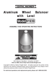
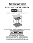
3 Ton Round Bottom
Long Ram Hydraulic Jack
36396
ASSEMBLY & OPERATING INSTRUCTIONS
3491 Mission Oaks Blvd., Camarillo, CA 93011
Visit our Web site at http://www.harborfreight.com
TO PREVENT SERIOUS INJURY,
READ AND UNDERSTAND ALL WARNINGS
AND INSTRUCTIONS BEFORE USE.
Copyright© 2003,2004 by Harbor Freight Tools®. All rights reserved. No
portion of this manual or any artwork contained herein may be reproduced in
any shape or form without the express written consent of Harbor Freight Tools.
For technical questions and replacement parts, please call 1-800-444-3353
THANK YOU for choosing a HARBOR FREIGHT TOOLS product. For future reference, please
complete the owner’s record below:
Model______________
Serial No._____________
Purchase Date_______________
SAVE THE RECEIPT, WARRANTY AND THESE INSTRUCTIONS. It is important that you read the
entire manual to become familiar with the unit BEFORE you begin assembly.
Finish:
Capacity:
Maximum Height:
Minimum Height:
Stroke:
Shaft Diameter:
Pinhole Size:
Weight:
Technical Specifications
Baked enamel
3 Ton
44-1/2”
24”
20”
1-7/64”
5/ ”
8
27-1/2 LBS.
The Round Bottom Jack is ideal for use on hydraulic cranes and engine hoists. The Jack
has a 20” stroke for jobs requiring a large lift.
Safety Warnings and Precautions
WARNING: When using product, basic safety precautions should always be followed to
reduce the risk of personal injury and damage to equipment.
Read all instructions before using this product!
1.
Keep work area clean. Cluttered areas invite injuries.
2.
Observe work area conditions. Keep work area well lit.
3.
Store idle equipment. When not in use, the Hydraulic Jack or the product it mounts on must be
stored in a dry location to inhibit damage from moisture and salt air.
4.
Check for damaged parts. Before using the Hydraulic Jack, any part that appears damaged
should be carefully checked to determine that it will operate properly and perform its intended
function. Check for any broken or damaged parts and any other conditions that may affect its
operation. Replace or repair damaged or worn parts immediately.
5.
Replacement parts and accessories. When servicing, use only identical replacement parts.
Use of any other parts will void the warranty.
6.
Do not force product. Do not use inappropriate attachments in an attempt to exceed the Hydraulic
Jack’s lifting capacity.
7.
Use the right product for the job. Do not attempt to force a small Jack or attachment to do the
work of a larger industrial Jack. There are certain applications for which this Jack was designed.
Do not modify this Jack and do not use this Jack for a purpose for which it was not intended. Do
not use on airplanes. Never attempt to install a base onto this Jack.
8.
Use eye and ear protection. Always wear ANSI approved impact safety goggles when installing
or using this product.
9.
Dress properly. Do not wear loose clothing or jewelry as they can be caught in moving parts.
Protective, electrically non-conductive clothes and non-skid footwear are recommended when
installing or using this product. Wear restrictive hair covering to contain long hair. Wear gloves to
protect hands.
SKU 36396
Page 2
10. Keep children away. Children must never be allowed in the work area.
11. Do not overreach. Keep proper footing and balance at all times. Do not reach over or
across the Jack during use.
12. Never leave the product unattended while supporting an object.
13. Remove adjusting keys and wrenches. Check that keys and adjusting wrenches are removed
from the tool or machine work surface before operating.
14. Never place your hands or other body parts near a hydraulic fluid leak. Never check for a
leak with your hands or other body parts. High-pressure fluid can be forced under your skin
resulting in serious injury.
15. Always make certain that the Hydraulic Jack and the product it is used with are set on a
flat, level and secure surface that is capable of supporting the combined weight of the
Hydraulic Jack, accompanying accessories and the weight of any material that is moved or
lifted. Make certain that the Jack is undamaged and mounted securely before use.
16. Read and adhere to the entire owner’s manual of any product that is used with the Hydraulic
Jack.
17. Always use the Jack within its rated weight load capacity, (3 tons = 6,000 Lbs.).
18. The Jack is designed for lifting only. Always use stationary supports after object is lifted.
Avoid using the Jack on slanted surfaces. Loading should be centered on the ram perpendicular
to the base.
19. Never put any part of your body under any object supported by the Jack at any time.
20. Not to be used for aircraft purposes.
Warning:
The warnings, cautions, and instructions discussed in this
instruction manual cannot cover all possible conditions and
situations that may occur. It must be understood by the operator
that common sense and caution are factors which cannot be built
into this product, but must be supplied by the operator.
Assembly/Operation
NEVER operate the Jack with low or no hydraulic oil
(see section on “Adding Hydraulic Oil”, page 4).
Mounting
Hole #1
Your 3 Ton Long Ram Round Bottom Hydraulic Jack will require complete
Ram (6)
assembly and installation prior to use. It is important that you read the entire
manual to become familiar with the product BEFORE you assemble and use the
Mounting
Hydraulic Jack. Before assembling and operating the Hydraulic Jack be sure
Points
that you have all parts described in the Parts List and Assembly Diagram located
on the last pages of this manual.
Valve
1. Attach the Hydraulic Jack to the product you are using. Secure the Valve
Body (1)
Body (1) to the product by inserting a pin (not included) through the holes in
Mounting
the Valve Body (1) and properly securing it, (See Mounting Hole #1, right).
Hole #2
Slide another pin (not included) through the product and Ram (6) (See
Mounting Hole #2, right), securing it as well. Make sure the pins’ diameters are a push fit with
just enough clearance so they move freely. The pins should be held in place with appropriate
e-clips or hardened cotter pins (neither one included).
SKU 36396
Page 3
Note: Only use pins that are intended for supporting this type of Jack, are capable of
supporting 3 Tons, and ensure that the pins are properly secured before use.
Note: This Jack is not intended for horizontal use.
2.
Insert the Handle (26) into the Handle Socket (27).
Raising and Lowering
1.
To raise the Hydraulic Jack turn the Release Valve (18) clockwise until the valve is tightly
closed. Pump the Handle (26) to raise the Jack. Continue to pump the Handle (26) until the
Hydraulic Jack is at the desired height.
2.
To lower the Jack, first verify that the area under the object is clear, then turn the Release Valve
(18) counterclockwise. This will release pressure in the Jack and cause the Jack to lower.
Adding Hydraulic Oil
1.
Turn the Release Valve (18) counterclockwise until Jack is completely lowered. Remove the
Oil Plug (11) from the Oil Chamber (10). Fill the Oil Chamber (10) with oil. Use a high quality
hydraulic oil. Note: The capacity of the oil chamber is 17.6 ounces.
Hydraulic System Bleeding Instructions
If the Hydraulic Jack begins to lose power and efficiency, it may be a result of air being trapped
in the hydraulic system. Follow the steps shown below to bleed the air from the hydraulic system.
Caution: Make certain that the Hydraulic Jack is not under load while bleeding the system.
1.
Remove oil chamber’s Oil Plug (11).
2.
Pump the Handle (26) to raise the Jack to its highest position. Open the Release Valve (18).
Release the Handle (26) to lower the Jack. Repeat pumping the Handle a number of times to
force the hydraulic oil through the system.
3.
Top off the oil chamber with hydraulic oil. Tighten the Oil Plug (11). The bleeding process is
now complete.
4.
Test the Hydraulic Jack to be certain it is working properly. Only proceed after you ensure that
it is working properly.
PLEASE READ THE FOLLOWING CAREFULLY
THE MANUFACTURER AND/OR DISTRIBUTOR HAS PROVIDED THE PARTS DIAGRAM IN THIS
MANUAL AS A REFERENCE TOOL ONLY. NEITHER THE MANUFACTURER NOR DISTRIBUTOR MAKES ANY
REPRESENTATION OR WARRANTY OF ANY KIND TO THE BUYER THAT HE OR SHE IS QUALIFIED TO MAKE
ANY REPAIRS TO THE PRODUCT OR THAT HE OR SHE IS QUALIFIED TO REPLACE ANY PARTS OF THE
PRODUCT. IN FACT, THE MANUFACTURER AND/OR DISTRIBUTOR EXPRESSLY STATES THAT ALL REPAIRS
AND PARTS REPLACEMENTS SHOULD BE UNDERTAKEN BY CERTIFIED AND LICENSED TECHNICIANS
AND NOT BY THE BUYER. THE BUYER ASSUMES ALL RISK AND LIABILITY ARISING OUT OF HIS OR HER
REPAIRS TO THE ORIGINAL PRODUCT OR REPLACEMENT PARTS THERETO, OR ARISING OUT OF HIS OR
HER INSTALLATION OF REPLACEMENT PARTS THERETO.
SKU 36396
Page 4
Unpacking
When unpacking your 3 Ton Long Ram Hydraulic Round Bottom Jack, check to make sure
the following parts are included. If any parts are missing or broken, please call HARBOR
FREIGHT TOOLS at 1-800-444-3353.
Part #
1
2
3
4
5
Description
Valve Body
Copper Washer
Cylinder
O-Ring
O-Ring Retainer
Qty.
1
1
1
1
1
Part #
17
18
19
20
21
Description
Seal Ring
Release Valve
Steel Ball
Copper Washer
Pump Cylinder
Qty.
1
1
1
1
1
6
Ram
1
22
O-ring
1
7
8
9
10
11
12
13
16
Top Nut
O-Ring
Sealing Gasket
Oil Chamber
Oil Plug
Seal Ring
Tube
Steel Ball
1
1
1
1
1
1
1
1
23
24
25
26
27
28
29
Back Up Ring
Plunger
Link Pin
Handle
Handle Socket
Connecting Pin
Cotter Pin
1
1
1
1
1
3
3
Note: Some parts are listed and shown for illustration purposes only and are not available
individually as replacement parts.
Assembly/Parts Diagram
26
SKU 36396
Page 5