1
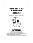
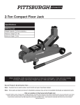
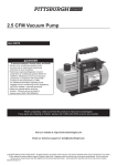
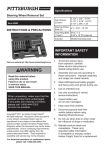
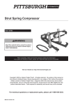
12 VDC AIR HORNS
WITH COMPRESSOR
94862
ASSEMBLY AND OPERATING INSTRUCTIONS
Due to continuing improvements, actual product may
differ slightly from the product described herein.
3491 Mission Oaks Blvd., Camarillo, CA 93011
Visit our Web site at http://www.harborfreight.com
Copyright © 2006 by Harbor Freight Tools®. All rights reserved. No portion of this
manual or any artwork contained herein may be reproduced in any shape or form
without the express written consent of Harbor Freight Tools.
For technical questions and replacement parts, please call 1-800-444-3353
Specifications
Item
Power Requirement
Horn Sizes
Horn Material
Sound
Air Source
Wire
Weight
Description
12 VDC, 10 watts, 8 ohms
Bell mouth: 3” and 2-7/8”; Length: 5-3/4”, 63/8” and 8-1/2”
Plastic, Red; Brass diaphragm
135 dB, high/low blast; Tones: high, medium,
low, and music
Compressor, electric (supplied)
14-16 AWG auto wire
2.95 lbs.
Save This Manual
You will need the manual for the safety warnings and precautions, assembly
instructions, operating and maintenance procedures, parts list and diagram. Keep
your invoice with this manual. Write the invoice number on the inside of the front
cover. Keep the manual and invoice in a safe and dry place for future reference.
Safety Warnings and Precautions
WARNING: When using tool, basic safety precautions should always be followed to reduce the risk of personal injury and damage to equipment.
Read all instructions before using this tool!
1.
Keep work area clean. Cluttered areas invite injuries.
2.
Observe work area conditions. Do not use machines or power tools in
damp or wet locations. Don’t expose to rain. Keep work area well lighted.
Do not use electrically powered tools in the presence of flammable gases or
liquids.
3.
Keep children away. Children must never be allowed in the work area. Do
not let them handle machines, tools, or extension cords.
4.
Use the right product for the job. There are certain applications for which
this product was designed. It will do the job better and more safely at the rate
for which it was intended. Do not modify this product and do not use for a
purpose for which it was not intended.
5.
Dress properly. Do not wear loose clothing or jewelry as they can be caught
in moving parts. Protective, electrically non-conductive clothes and non-skid
footwear are recommended when working. Wear restrictive hair covering to
contain long hair.
6.
Do not overreach. Keep proper footing and balance at all times. Do not
reach over or across running machines.
SKU 94862
For technical questions, please call 1-800-444-3353
Page 2
7.
Check for damaged parts. Before using this product, any part that appears
damaged should be carefully checked to determine that it will operate
properly and perform its intended function. Check for any other condition that
may affect proper operation. Any part that is damaged should be properly
repaired or replaced by a qualified technician. Do not use the product if the
switch does not turn On and Off properly.
8.
Replacement parts and accessories. When servicing, use only identical
replacement parts. Use of any other parts will void the warranty. Only use
accessories intended for use with this product. Approved accessories are
available from Harbor Freight Tools.
9.
Do not operate tool if under the influence of alcohol or drugs. Read
warning labels if taking prescription medicine to determine if your judgment or
reflexes are impaired while taking drugs. If there is any doubt, do not operate
this product.
Note: Performance of this tool may vary depending on variations in battery power.
Product Specific Safety Precautions
Warning: The brass components of this product contain lead, a chemical known
to the State of California to cause birth defects (or other reproductive harm).
(California Health & Safety Code 25249.5 et seq.)
1.
During installation, remove ignition keys from the vehicle and set the parking
brake.
2.
Only connect the positive (+) hot lead to a fused terminal or circuit.
3.
Avoid short circuits or burns. Do not wear rings, watches, or other metallic
objects around your hands and arms.
Warning: The warnings, cautions, and instructions discussed in this instruction
manual cannot cover all possible conditions and situations that may occur. It
must be understood by the operator that common sense and caution are factors
which cannot be built into this product, but must be supplied by the operator.
Warning: People with pacemakers should consult their physician(s) before using
this product. Electromagnetic fields in close proximity to a heart pacemaker could
cause interference to or failure of the pacemaker.
Unpacking
When unpacking, check to make sure the following parts are included. Refer to the
Parts List and Parts Photo at the end of this manual. If any parts are missing or
broken, please call Harbor Freight Tools at the number on the cover of this manual.
SKU 94862
For technical questions, please call 1-800-444-3353
Page 3
Installation
Caution: If you are not familiar with working around vehicle engine
compartments, the installation should be completed by a qualified technician.
Before attempting installation of the Air Horns, remove the keys from the vehicle
ignition, set the emergency brake, and place wheel chocks.
1.
Lift the vehicle hood and find a suitable location to mount the Horns and
Compressor.
This location must shelter the Compressor (4) and Horns (1, 2, and 3) from
incoming rain, road water, and mud from under the vehicle. It also must be
away from all moving engine parts and heat.
2.
Using a Bolt and Nut (9), mount the Compressor (4) to the vehicle chassis in
a vertical position (air outlets facing up). See illustration middle-right.
A hole may need to be drilled in the chassis frame to accomplish this.
Always be careful that no electrical wires or cables are in the drilling path.
The head of the Bolt slides into the Compressor mounting bracket. Securely
tighten Nut.
3.
Mount the Horns near the Compressor so that they are pointing forward and
slightly downward for maximum efficiency. The head of the Bolt slides into the
Horn mounting bracket. Securely tighten Nut. See illustration middle-left.
Horn Mounting
Compressor
Mounting
4.
Mount the Electric Relay (6) to the chassis frame near the Compressor using
a Bolt and Nut. Securely tighten.
5.
Connect the Compressor to the Horns using the rubber Tubing (5) and the
Y-Connector (8). Cut the rubber tubing to the desired length. Do not fold or
kink tubing. See illustration below.
SKU 94862
For technical questions, please call 1-800-444-3353
Page 4
Tubing (5)
Horns (1, 2, and 3)
Compressor (4)
Y-Connector (8)
6.
Make the connections to the Compressor (4) and the Electric Relay (6) as
shown on the wiring diagram below.
Wiring Diagrams
Always use vehicle terminal type connectors (not supplied) on all connections.
Never wrap wires around terminals as they could fall off. Connect terminal #30 on
the Electric Relay (6) to a 30A fused circuit.
Note: Some vehicles may employ a positive ground system. If this is the case, refer
to the wiring diagram above-left. Pay attention to polarity. If the Compressor turns on
and the Horns do not sound, reverse the Compressor connections (+ / -).
7.
The Air Horns will now sound when the vehicle horn is pushed.
Maintenance
1.
Periodically add a few drops of light oil to each air outlet of the Compressor.
First remove air outlet tubes. Energize the Compressor. Excess oil will be
blown out. Wear ANSI approved safety glasses for this process.
2.
Periodically check the Air Horn, Relay, and Compressor hardware for
tightness. Also check for secure wire connections.
SKU 94862
For technical questions, please call 1-800-444-3353
Page 5
Parts List
Item
1
2
3
4
5
6
7
8
9
10
Description
Horn, Large
Horn, Medium
Horn, Small
Compressor
Tubing
Relay
Switch
Y-Connector, Tubing
Hardware, Nuts and Bolts
Separator, Mounting
Qty
1
1
2
1
1
1
1
1
4
3
NOTE: Some parts are listed and shown for illustration purposes only and are not
available individually as replacement parts.
Parts Photo
(1)
(4)
(3)
(2)
(6)
(9)
(7)
(5)
(10)
(8)
SKU 94862
(9)
(9)
For technical questions, please call 1-800-444-3353
Page 6
PLEASE READ THE FOLLOWING CAREFULLY
THE MANUFACTURER AND/OR DISTRIBUTOR HAS PROVIDED THE PARTS DIAGRAM
IN THIS MANUAL AS A REFERENCE TOOL ONLY. NEITHER THE MANUFACTURER NOR
DISTRIBUTOR MAKES ANY REPRESENTATION OR WARRANTY OF ANY KIND TO THE
BUYER THAT HE OR SHE IS QUALIFIED TO MAKE ANY REPAIRS TO THE PRODUCT OR
THAT HE OR SHE IS QUALIFIED TO REPLACE ANY PARTS OF THE PRODUCT. IN FACT,
THE MANUFACTURER AND/OR DISTRIBUTOR EXPRESSLY STATES THat ALL REPAIRS
AND PARTS REPLACEMENTS SHOULD BE UNDERTAKEN BY CERTIFIED AND
LICENSED TECHNICIANS AND NOT BY THE BUYER. THE BUYER ASSUMES ALL RISK
AND LIABILITY ARISING OUT OF HIS OR HER REPAIRS TO THE ORIGINAL PRODUCT
OR REPLACEMENT PARTS THERETO, OR ARISING OUT OF HIS OR HER INSTALLATION
OF REPLACEMENT PARTS THERETO.
SKU 94862
For technical questions, please call 1-800-444-3353
Page 7