1
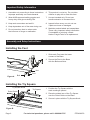
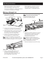
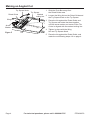
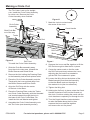
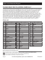
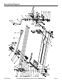
Important Safety Information
1. Assemble only according to these instructions.
Improper assembly can create hazards.
6. This product is not a toy. Do not allow
children to play with or near this item.
2. Wear ANSI-approved safety goggles and
heavy-duty work gloves during use.
7. Use as intended only. Do not use
handle extension to increase force.
3. Keep work area clean and well lit.
8. Inspect before every use; do not use
if parts are loose or damaged.
4. Keep bystanders out of the area during use.
5. Do not use when tired or when under
the influence of drugs or medication.
9. Maintain product labels and nameplates.
These carry important safety information.
If unreadable or missing, contact
Harbor Freight Tools for a replacement.
Assembly and Setup Instructions
Installing the Feet
1. Slide each Foot onto the lower
corners of the Base.
2. Secure the Feet to the Base
with the Bolts and Nuts.
Nut
Figure A
Foot
Bolt
Installing the Try Square
Try Square Knob
Ruled Guide
Try Square
1. Position the Try Square with the
scale markings upward.
2. Place the slotted arm of the Try Square
over the Ruled Guide on the Base.
3. Secure in place with the Try Square Knob.
Figure B
Page 2
For technical questions, please call 1-888-866-5797.
ITEM 68979
Operating Instructions
Make several practice cuts on scrap tile
before attempting to make finish cuts.
Use a sturdy workbench, or place the machine
on the floor to increase your leverage.
Before beginning, mark the cut line on
the tile with a soft carpenter’s pencil,
a grease pencil or a washable marker.
Making a Straight Cut
1. Remove the Circle Cutter
assembly if it is installed.
Try Square Knob
Ruled Guide
Try Square
Tile
Note: Good results require applying proper
pressure and scoring the tile properly.
This depends largely upon the
operator and requires practice.
Push Bar
Figure C
Cutting Line
2. Loosen the Try Square Knob and slide the
Try Square out so there is room for the tile.
3. With the glazed side up, place the tile against
the Ruled Guide, with the marked cutting
line directly under the Cutting Wheel.
4. Slide the Try Square to the edge of the
tile and tighten the Try Square Knob.
Note: Once the Try Square is secured at the
desired setting, you can make multiple cuts of the
same size without marking the cut line on the tile.
Breaking Bar
Figure E
6. Slide the Push Bar handle back until the
Breaking Bar is centered over the tile,
and lower the Handle to press the
Breaking Bar onto the tile.
Note: Make sure that the score line is
aligned with the center of the Breaking Bar
and the Breaking Bar is centered over
the tile, straddling the score line.
7. Remove tile pieces from the Tile Cutter.
Figure D
Cutting Wheel
5. Swing the Breaking Bar up and out of
the way, then holding the tile firmly,
score along the marked cutting line with
the Cutting Wheel several times.
ITEM 68979
For technical questions, please call 1-888-866-5797.
Page 3
Making an Angled Cut
Try Square Knob
Ruled Guide
1. Slide the Push Bar away from
the Ruled Guide area.
Try Square
Marked
2. Loosen the Wing Nut on the Ruled Guide and
cutting line
the Try Square Knob on the Try Square.
Wing Nut
Arrow
Marker
Figure F
Cente
r of Til
Tile
e Cutt
er
3. Place the tile against the Ruled Guide and
Try Square and rotate the them together
until the arrow marker and center of the Tile
Cutter is aligned with the marked cutting line.
4. Tighten in place with the Wing
Nut and Try Square Knob.
5. Place the tile against the Ruled Guide, and
make the cut following steps 4-6 on page 4.
Page 4
For technical questions, please call 1-888-866-5797.
ITEM 68979
Making a Circle Cut
The Tile Cutter is set up for straight
cuts. Install the Circle Cutter Assembly
for circle cuts. Remove the Circle
Cutter Assembly when finished.
Figure H
Circle Cutter
Assembly
7. Mark the circle to cut and mark
the center of the circle.
Lever
Crank Handle
Slide Push Bar
out of the way
Nut
Bar
Tracks
Lever
Threaded Rod
Bar
Drill Point
Blade
Figure G
Pressing Plate
Drill Point
To install the Circle Cutter Assembly:
1. Slide the Push Bar assembly away
from the circle cutter area, towards the
Buffer Sleeves and Ruled Guide.
2. Remove the Nut holding the Pressing Plate
to the Assembly and set both pieces aside.
Figure I
8. Squeeze the Lever and Bar together to lift the
Drill Point enough to slide the tile in place.
9. Center the center mark on the tile under
the Drill Point and slowly release the Lever,
adjusting the tile location as needed to
get the Drill Point centered in place.
3. Place the Circle Cutter Assembly onto the
Tracks with the Lever pointed away from
the Buffer Sleeves and Ruler Guide.
10. Loosen the Wing Nut on the bottom of the
Blade Assembly and slide the Assembly
so that the Blade rests on the edge of
the marked circle (the circumference).
4. Align the Drill Point with the center
of the hole in the Base.
11. Tighten the Wing Nut.
5. Place the Pressing Plate under the Tracks
and Circle Cutter Assembly, with the threaded
rod inserted upward through the hole in
the base of the Circle Cutter Base. Reinstall the Nut and Washer and tighten.
6. Assemble the Circle Cutter Assembly onto
the Tile Cutter (see Assembly section).
ITEM 68979
12. Holding the tile firmly in place, rotate the Crank
Handle clockwise to drill into the tile and cut
the circle. Continue rotating the crank until the
circle has been completely cut through the tile.
13. Turn the Crank Handle counterclockwise
to raise the Blade above the tile, then
squeeze the Lever and Bar together
and remove the cut tile pieces.
For technical questions, please call 1-888-866-5797.
Page 5
Parts List and Assembly Diagram
PLEASE READ THE FOLLOWING CAREFULLY
THE MANUFACTURER AND/OR DISTRIBUTOR HAS PROVIDED THE PARTS LIST AND ASSEMBLY
DIAGRAM IN THIS MANUAL AS A REFERENCE TOOL ONLY. NEITHER THE MANUFACTURER
OR DISTRIBUTOR MAKES ANY REPRESENTATION OR WARRANTY OF ANY KIND TO THE
BUYER THAT HE OR SHE IS QUALIFIED TO MAKE ANY REPAIRS TO THE PRODUCT, OR
THAT HE OR SHE IS QUALIFIED TO REPLACE ANY PARTS OF THE PRODUCT. IN FACT, THE
MANUFACTURER AND/OR DISTRIBUTOR EXPRESSLY STATES THAT ALL REPAIRS AND PARTS
REPLACEMENTS SHOULD BE UNDERTAKEN BY CERTIFIED AND LICENSED TECHNICIANS,
AND NOT BY THE BUYER. THE BUYER ASSUMES ALL RISK AND LIABILITY ARISING OUT OF
HIS OR HER REPAIRS TO THE ORIGINAL PRODUCT OR REPLACEMENT PARTS THERETO,
OR ARISING OUT OF HIS OR HER INSTALLATION OF REPLACEMENT PARTS THERETO.
Parts List
Part
1
2
3
4
5
6
7
8
9
10
11
12
13
14
15
16
17
18
19
20
21
22
Description
Nut
Foot
Washer
Bolt
Base
Cushion
Bolt
Washer
Nut
Nut
Lock Washer
Washer
Angle Indicator
Bolt
Angle Scale
Width Guide
Washer
Angle Nut
Washer
Width Knob
Bolt
Breaking Bar
Part
23
24
25
26
27
28
29
30
31
32
33
34
35
36
37
38
39
40
41
42
43
44
Description
Bolt
Cutting Wheel
Support
Washer
Bolt
Collar
Slide
Bolt
Lock Nut
Pivot
Carriage
Lock Nut
Bushing
Bar
Handle
Nut
Knob
Crank
Nut
Washer
Arbor
Nut
Part
45
46
47
48
49
50
51
52
53
54
55
56
57
58
59
60
61
62
63
64
Description
Washer
Nut
Washer
Circle Cutter Base
Lever
Spring
Bolt
Washer
Pin
Cover
Washer
Bolt
Nut
Washer
Press Plate
Center Blade
Wing Nut
Washer
Blade
Nut
Record Product’s Serial Number Here:
Note: If product has no serial number, record month and year of purchase instead.
Note: Some parts are listed and shown for illustration purposes only,
and are not available individually as replacement parts.
Page 6
For technical questions, please call 1-888-866-5797.
ITEM 68979
Assembly Diagram
ITEM 68979
For technical questions, please call 1-888-866-5797.
Page 7
Limited 90 Day Warranty
Harbor Freight Tools Co. makes every effort to assure that its products meet high quality
and durability standards, and warrants to the original purchaser that this product is free from
defects in materials and workmanship for the period of 90 days from the date of purchase. This
warranty does not apply to damage due directly or indirectly, to misuse, abuse, negligence or
accidents, repairs or alterations outside our facilities, criminal activity, improper installation,
normal wear and tear, or to lack of maintenance. We shall in no event be liable for death,
injuries to persons or property, or for incidental, contingent, special or consequential damages
arising from the use of our product. Some states do not allow the exclusion or limitation of
incidental or consequential damages, so the above limitation of exclusion may not apply to
you. THIS WARRANTY IS EXPRESSLY IN LIEU OF ALL OTHER WARRANTIES, EXPRESS
OR IMPLIED, INCLUDING THE WARRANTIES OF MERCHANTABILITY AND FITNESS.
To take advantage of this warranty, the product or part must be returned to us with
transportation charges prepaid. Proof of purchase date and an explanation of the complaint
must accompany the merchandise. If our inspection verifies the defect, we will either repair or
replace the product at our election or we may elect to refund the purchase price if we cannot
readily and quickly provide you with a replacement. We will return repaired products at our
expense, but if we determine there is no defect, or that the defect resulted from causes not
within the scope of our warranty, then you must bear the cost of returning the product.
This warranty gives you specific legal rights and you may also
have other rights which vary from state to state.
3491 Mission Oaks Blvd. • PO Box 6009 • Camarillo, CA 93011 • 1-888-866-5797