1
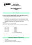
Pallet Jack
Item 68760 / 68761
Instructions and precautions
Specifications
Capacity
2-1/2 Ton (5,000 LB.)
Control Lever
Fork
Height
3 Position
Maximum 7-1/2 IN.
Minimum
3 IN.
Fork Length
47-1/2 IN.
Fork Width
6-1/4 IN.
Width over Forks
27 IN.
Steering Wheel Dia.
7 IN.
Visit our website at:
http://www.harborfreight.com
Read this material before
using this product.
Failure to do so can result
in serious injury.
Save this manual.
When unpacking, make sure that the product is intact and undamaged.
If any parts are missing or broken, please call
1‑800‑444‑3353 as soon as possible.
Copyright© 2011 by Harbor Freight Tools®. All rights reserved. No portion of this document or any
artwork contained herein may be reproduced in any shape or form without the express written consent
of Harbor Freight Tools. Diagrams within this document may not be drawn proportionally. Due to
continuing improvements, actual product may differ slightly from the product described herein. Tools
required for assembly and service may not be included.
For technical questions or replacement parts, please call 1‑800‑444‑3353.
Important Safety Information
1. Do not exceed 5,000 lb. capacity.
Be aware of dynamic loading!
Sudden load movement may
briefly create excess load
causing product failure.
Do not use the Jack unless all
components are operating properly.
13. Maintain product labels and
nameplates. These carry important
safety information. If unreadable
or missing, contact Harbor
Freight Tools for a replacement.
2. Wear ANSI-approved safety
goggles, heavy-duty work
gloves and non-skid footwear
during assembly and use.
3. Use as intended only. Do not
use to support people or animals
or use for aircraft purposes.
4. Keep clear of fork and
load while raised.
5. Only use on flat, level
surface able to withstand
weight of truck and load.
6. Do not leave unattended
while under load.
7. Only use with balanced,
properly secured load.
8. Inspect before every use; do not
use if parts loose or damaged.
9. This product is not a toy. Do
not allow children to play
with or near this item.
10. Do not operate while under the
influence of alcohol or drugs.
11. Do not wear loose clothing or
jewelry, and wear restrictive
hair covering, as they can be
caught in moving parts.
12. Before each use, carefully inspect
the wheels, Handle Frame, Chassis
and Handle for proper operation.
Page 2
For technical questions, please call 1-800-444-3353.
Item 68760 / 68761
Set Up Instructions
Read the entire
Important Safety
Information section
at the beginning of this
document including all
text under subheadings
therein before set up or
use of this product.
The Control Lever
The Control Lever on the Handle has
three positions: Raise, Drive and Lower.
Control Lever
Handle
Lower
Drive
Handle Assembly
You will need to attach the Handle
to the base of the Jack before
first use. Refer to the Parts Lists
and Diagrams near the end of
this manual for part numbers.
Tighten hardware to no more
than 43 ft-lb, using a torque
wrench (sold separately).
1. Remove the three Screws (D611)
from the Handle Bracket (D151).
2. Set the Handle (D610A or B) on
the Handle Bracket, making sure
that the Chain (D612) and the
Adjusting Bolt (D614) pass through
the large opening in the center of
the Handle Bracket and the hole
in the center of the Shaft (D153).
3. Slide the Washers (D616)
onto the Screws (D611) then
insert the Screws through the
Handle into the Handle Bracket
(D151) and tighten securely.
4. Raise the Lever Plate (D132) and
insert the Adjusting Bolt (D614)
into the slotted open end, keeping
the Adjusting Nut (D615) on the
underside of the Lever Plate.
Item 68760 / 68761
Raise
Figure 1
a. Raise - Move the Handle down
to its lowest position. Pump
the Handle frame up and
down to lift the Jack Forks.
b. Drive - Move the Handle to
the center position. The Jack
Forks do not change position
when in drive. This position is
used when the load is moved
from one location to another.
c. Lower - Hold the Handle up
in its highest position. This
position automatically moves
the Forks to their lowest level.
This position is only in place as
long as you hold the Handle up.
The Handle moves back to the
Drive position when released.
If the Handle does not function
properly, make adjustments as
described in the following chart
by turning the Adjusting Nut
(D615). After each adjustment,
check that all positions of the
For technical questions, please call 1-800-444-3353.
Page 3
Control Lever function properly
and re-adjust if needed.
Position
Drive
Drive
Lower
Raise
Problem
Turn Adjusting
Nut (D615)
Forks rise
Clockwise
instead of
until pumping
staying in
action does not
neutral.
raise forks.
Forks lower,
or lower when Counterclockwise
pumping handle
until forks do
is in Drive
not lower.
position.
Clockwise until
Forks do
raising the Control
Lever lowers
not lower.
the Forks.
Counterclockwise
until the Forks
Forks do not
elevate while
elevate.
pumping in the
Raise position.
Bleeding the
Hydraulic Jack
Before every use, check that
there is enough oil in the Jack
by lowering the Forks, removing
the Oil Plug (D149) from the
Jack and filling the Jack with
high quality hydraulic oil to
the level of the fill hole.
To Bleed the Jack of excess air:
1. Hold the Control Lever up to its
highest position to lower the Forks.
2. Remove the Oil Plug.
3. Pump the Handle up and
down several times to push
excess air out of the Jack.
4. If needed add oil to the
level of the oil fill hole.
Operating Instructions
Read the entire
Important Safety
Information section
at the beginning of this
document including all
text under subheadings
therein before set up or
use of this product.
1. Hold the Control Lever in its
highest position to lower the Forks,
then release the Control Lever.
2. Slide the Forks under the load,
being careful to center the load over
the Forks, and to have the main
weight of the load resting as near
as possible to the Steering Wheels.
3. Push the Control Lever down to
the Raise position, then pump the
Handle until the load is raised off
the floor and is resting on the Forks.
4. Move the Control Lever to the
Drive position and wheel the
load to the desired location.
5. Hold the Control Lever in its
highest position to lower the Forks,
then release the Control Lever.
6. Slide the Forks out from
under the load.
7. When finished using the Jack, hold
the Control Lever in its highest
position to Lower the Forks.
8. Store in a clean dry place
away from children.
5. Replace the Oil Plug.
Page 4
For technical questions, please call 1-800-444-3353.
Item 68760 / 68761
PLEASE READ THE FOLLOWING CAREFULLY
The manufacturer and/or distributor has provided the parts list and assembly
diagram in this document as a reference tool only. Neither the manufacturer
or distributor makes any representation or warranty of any kind to the
buyer that he or she is qualified to make any repairs to the product, or
that he or she is qualified to replace any parts of the product. In fact, the
manufacturer and/or distributor expressly states that all repairs and parts
replacements should be undertaken by certified and licensed technicians,
and not by the buyer. The buyer assumes all risk and liability arising out of
his or her repairs to the original product or replacement parts thereto,
or arising out of his or her installation of replacement parts thereto.
Record Serial Number Here:
Note: If product has no serial number, record
month and year of purchase instead.
Note: Some parts are listed and shown for illustration purposes
only, and are not available individually as replacement parts.
Item 68760 / 68761
For technical questions, please call 1-800-444-3353.
Page 5
Maintenance
Read the entire Important Safety Information section
at the beginning of this document including all text under
subheadings therein before set up or use of this product.
1. Lower Jack completely after every use.
2. Periodically use motor oil or grease to lubricate all moveable parts.
3. Replace handle if pin breaks.
Page 6
For technical questions, please call 1-800-444-3353.
Item 68760 / 68761
Troubleshooting
Problem
Possible Causes
The Forks do not Insufficient oil.
raise completely.
The forks will
1. Insufficient oil.
not raise.
The forks will
not descend.
Fluid Leak.
Likely Solutions
Refill Jack with hydraulic oil
through Oil Plug hole.
1. Refill Jack with hydraulic oil
through Oil Plug hole.
2. Air in valve chamber.
2. Raise the Control Lever to the
Upper position and pump the
handle several times.
3. Old/contaminated oil.
1. Deformed piston rod.
3. Change oil and replace Seals.
1. Replace piston rod and cylinder.
2. Piston rod rusted.
2. Lubricate/replace rod. Keep Jack in
lowered position when not in use.
3. Control handle, bolt, or
3. Replace the Handle Assembly.
chain broken or missing.
Component, likely seal,
Inspect and replace worn or damaged parts.
worn or damaged.
1. Contaminated oil clogging valve. 1. Clean valve with kerosene and change oil.
Forks descend
without operating 2. Hydraulic component damaged. 2. Replace damaged part.
release valve.
Follow safety precautions whenever
diagnosing or servicing the tool.
Item 68760 / 68761
For technical questions, please call 1-800-444-3353.
Page 7
Handle Parts List and Diagram
Part
D601
D602
D603
D604
D605
D606
D607
D608
D609
Page 8
Description
Spring
Blade Spring
Roller
Elastic Pin
Elastic Pin
Elastic Pin
Elastic Pin
Control Handle
Pull Board
Qty
1
1
1
1
1
1
1
1
1
Part
D610B
D610A
D611
D612
D613
D614
D615
D616
Description
Handle (For Type A)
Handle (For Type B)
Screw
Chain
Pin
Adjusting Bolt
Adjusting Nut
Washer
For technical questions, please call 1-800-444-3353.
Qty
1
1
3
1
1
1
1
3
Item 68760 / 68761
Fork Frame Parts List and Diagram
Part
D201
D202
D203
D204
D205
D206
D206D
D207
D208
D208D
D209
D209D
D210
D211
D212
D213
D214
D215
Description
Screw
Oil Holder
Rocker Arm
Elastic Pin
Retaining Ring
Joint (For Type A)
Joint (For Type B)
Shaft
Push Rod (For Type A)
Push Rod (For Type B)
Nut (For Type A)
Nut (For Type B)
Pin
Shaft
Shaft
Elastic Pin
Shaft
Roller Frame
Item 68760 / 68761
Qty
1
1
1
1
2
2
2
2
2
2
2
2
2
1
2
2
2
2
Part
D216
D217
D218
D219
D220
D221
D222
D223
D224
D225
D226
D227
D228
D229
D230
D231
D232
Description
Elastic Pin
Roller Shaft
Fork Frame
Washer
Bearing
Loading Roller
Linking Plate
Elastic Pin
Bushing
Bushing
Bolt
Enter Roller
Nut
Loading Roller
Roller Shaft
Washer
Washer
For technical questions, please call 1-800-444-3353.
Qty
2
4
1
4
4
4
4
8
4
2
2
2
2
2
2
2
4
Page 9
Pump Parts List
Part
D101
D102
D103
D104
D105
D106
D106B
D107
D107B
D108
D109
D110
D110B
D111
D111B
D112
D113
D115
D116
D118
D119
D120
D121
D122
D123
D124
D127
D129
D130
Page 10
Description
Pump Piston Rod
Washer
Spring
Dust Ring
Y-Seal
Screw (For Type A)
Screw (For Type B)
O-Ring (For Type A)
O-Ring (For Type B)
Spring
Pumping Valve Spindle
Pumping Valve Seat
(For Type A)
Screw (For Type B)
O-Ring (For Type A)
O-Ring (For Type B)
Steel Ball
Pump Base
Elastic Pin
Steering Wheel
Thrust Plate
Oil Holder
Retaining Ring
Bearing Cover
Bearing
Elastic Pin
Dust Cover
Bearing
Spring
Strike Pin
Qty
1
1
1
1
1
1
1
1
1
1
1
1
1
1
1
1
1
1
2
1
1
1
1
1
2
2
4
1
1
Part
D131
D132
D133
D134
D135
D136
D137
D139
D140
D141
D142
D143
D144
D145
D146
D147
D148
D149
D150
D151
D152
D153
D154
D155
D156
D157
D158
D159B
D160B
Description
O-Ring
Lever Plate
Adjusting Screw
Nut
O-Ring
Axle Sleeve
Adjusting Bolt
Safety Valve Spindle
Spring
O-Ring
Screw
O-Ring
Y-Seal
Elastic Pin
Steel Ball
Piston Rod
Dust Ring
Oil Plug
Shaft
Handle Bracket
Pressure Roller
Shaft
Elastic Pin
Elastic Pin
Bushing
Seal Washer
Bushing
Sleeve (For Type B)
Screw (For Type B)
For technical questions, please call 1-800-444-3353.
Qty
2
1
1
1
1
1
1
1
1
1
1
1
1
1
1
1
1
1
1
1
1
1
1
1
1
1
2
1
1
Item 68760 / 68761
Pump Diagram
Item 68760 / 68761
For technical questions, please call 1-800-444-3353.
Page 11
Limited 90 Day Warranty
Harbor Freight Tools Co. makes every effort to assure that its products meet high quality and durability
standards, and warrants to the original purchaser that this product is free from defects in materials
and workmanship for the period of 90 days from the date of purchase. This warranty does not apply
to damage due directly or indirectly, to misuse, abuse, negligence or accidents, repairs or alterations
outside our facilities, criminal activity, improper installation, normal wear and tear, or to lack of
maintenance. We shall in no event be liable for death, injuries to persons or property, or for incidental,
contingent, special or consequential damages arising from the use of our product. Some states do
not allow the exclusion or limitation of incidental or consequential damages, so the above limitation
of exclusion may not apply to you. This warranty is expressly in lieu of all other
warranties, express or implied, including the warranties of merchantability
and fitness.
To take advantage of this warranty, the product or part must be returned to us with transportation
charges prepaid. Proof of purchase date and an explanation of the complaint must accompany the
merchandise. If our inspection verifies the defect, we will either repair or replace the product at our
election or we may elect to refund the purchase price if we cannot readily and quickly provide you with
a replacement. We will return repaired products at our expense, but if we determine there is no defect,
or that the defect resulted from causes not within the scope of our warranty, then you must bear the
cost of returning the product.
This warranty gives you specific legal rights and you may also have other rights which vary from state
to state.
3491 Mission Oaks Blvd. • PO Box 6009
Camarillo, CA 93011 • (800) 444-3353