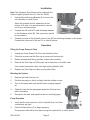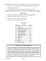
1
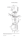
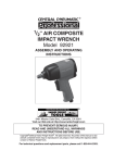
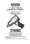
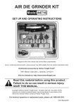
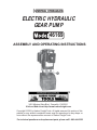
ELECTRIC HYDRAULIC
GEAR PUMP
46169
ASSEMBLY AND OPERATING INSTRUCTIONS
3491 Mission Oaks Blvd., Camarillo, CA 93011
Visit our Web site at http://www.harborfreight.com
Copyright © 2001 by Harbor Freight Tools. All rights reserved. No portion of this
manual or any artwork contained herein may be reproduced in any shape or
form without the express written consent of Harbor Freight Tools.
For technical questions and replacement parts, please call 1-800-444-3353
Specifications
ITEM
DESCRIPTION
Power
220 V,
Single
5 AVAC, 5 amp, single phase
115
VAC*,
10 Phase,
amp; 220
Motor
1 HP, 3450 / 2850 RPM;
Size: 9-3/8 (L) x 6.189 (dia.) inches
Relief Pressure
2100 PSI
Working Pressure
1800 PSI
Pump Size
1-1/4 (L) inches
Tank
1 gallon
Mounting Type
Vertical; Plate Size: 6-1/2 (W) x 6-1/2 (H) inches
Discharge Adapter
3/8 inch NPT, male 9/16 inch
Weight
58 lbs.
* The Electric Hydraulic Gear Pump comes prewired for 115
VAC. The unit can be rewired for 220 VAC by a licensed
electrician.
Save This Manual
You will need the manual for the safety warnings and precautions, assembly instructions,
operating and maintenance procedures, parts list and diagram. Keep your invoice with this
manual. Write the invoice number on the inside of the front cover. Keep the manual and
invoice in a safe and dry place for future reference.
Safety Warnings and Precautions
WARNING: When using tool, basic safety precautions should always be followed to
reduce the risk of personal injury and damage to equipment.
Read all instructions before using this tool!
1.
Keep work area clean. Cluttered areas invite injuries.
2.
Observe work area conditions. Do not use machines or power tools in damp or wet
locations. Don’t expose to rain. Keep work area well lighted. Do not use electrically
powered tools in the presence of flammable gases or liquids.
3.
Keep children away. Children must never be allowed in the work area. Do not let
them handle machines, tools, or extension cords.
4.
Store idle equipment. When not in use, tools must be stored in a dry location to
inhibit rust. Always lock up tools and keep out of reach of children.
5.
Do not force tool. It will do the job better and more safely at the rate for which it was
intended. Do not use inappropriate attachments in an attempt to exceed the tool
capacity.
6.
Use the right tool for the job. Do not attempt to force a small tool or attachment to
do the work of a larger industrial tool. There are certain applications for which this tool
was designed. Do not modify this tool and do not use this tool for a purpose for which
it was not intended.
REV 11/06
SKU 46169
Page 2
7.
Dress properly. Do not wear loose clothing or jewelry as they can be caught in
moving parts. Protective, electrically non-conductive clothes and non-skid footwear
are recommended when working. Wear restrictive hair covering to contain long hair.
8.
Use eye and ear protection. Always wear ANSI approved impact safety goggles.
Wear a full face shield if you are producing metal filings or wood chips. Wear an ANSI
approved dust mask or respirator when working around metal, wood, and chemical
dusts and mists.
9.
Do not overreach. Keep proper footing and balance at all times. Do not reach over
or across running machines.
10.
Maintain tools with care. Keep tools sharp and clean for better and safer
performance. Follow instructions for lubricating and changing accessories. Inspect
tool cords periodically and, if damaged, have them repaired by an authorized
technician. The handles must be kept clean, dry, and free from oil and grease at all
times.
11.
Disconnect power. Unplug tool when not in use.
12.
Remove adjusting keys and wrenches. Check that keys and adjusting wrenches
are removed from the tool or machine work surface before plugging it in.
13.
Avoid unintentional starting. Be sure the switch is in the Off position when not in
use and before plugging in. Do not carry any tool with your finger on the trigger,
whether it is plugged in or not.
14.
Stay alert. Watch what you are doing, use common sense. Do not operate any tool
when you are tired.
15.
Check for damaged parts. Before using any tool, any part that appears damaged
should be carefully checked to determine that it will operate properly and perform its
intended function. Check for alignment and binding of moving parts; any broken parts
or mounting fixtures; and any other condition that may affect proper operation. Any
part that is damaged should be properly repaired or replaced by a qualified
technician. Do not use the tool if any switch does not turn On and Off properly.
16.
Guard against electric shock. Prevent body contact with grounded surfaces such
as pipes, radiators, ranges, and refrigerator enclosures.
17.
Replacement parts and accessories. When servicing, use only identical
replacement parts. Use of any other parts will void the warranty. Only use accessories
intended for use with this tool. Approved accessories are available from Harbor
Freight Tools.
18.
Do not operate tool if under the influence of alcohol or drugs. Read warning
labels on prescriptions to determine if your judgment or reflexes are impaired while
taking drugs. If there is any doubt, do not operate the tool.
SKU 46169
Page 3
19.
Use proper size and type extension cord. If an extension cord is required, it must be
of the proper size and type to supply the correct current to the tool without heating up.
Otherwise, the extension cord could melt and catch fire, or cause electrical damage to
the tool. This tool requires use of an extension cord of 0 to 12 amps capability (up to
50 feet), with wire size rated at 16 AWG. Longer extension cords require larger size
wire. If you are using the tool outdoors, use an extension cord rated for outdoor use.
(signified by “WA” on the jacket).
20.
Maintenance. For your safety, service and maintenance should be performed
regularly by a qualified technician.
21.
If you have a heart pacemaker, operation of electrical equipment in close proximity
to a heart pacemaker could cause interference or failure of the pacemaker.
Note: Performance of this tool (if powered by line voltage) may vary depending on variations
in local line voltage. Extension cord usage may also affect tool performance.
Warning: The warnings, cautions, and instructions discussed in this instruction manual
cannot cover all possible conditions and situations that may occur. It must be understood by the operator that common sense and caution are factors which cannot be
built into this product, but must be supplied by the operator.
Unpacking
When unpacking, check to make sure that the unit is assembled as shown in the cover
photo. Also refer to the Parts List and Assembly Drawing at the end of this manual. If any
parts are missing or broken, please call Harbor Freight Tools at the number on the cover of
this manual as soon as possible.
Hydraulic Pump Warnings and Precautions
1.
Never place your hands or other body parts near a hydraulic fluid leak. Never check
for a leak with your hands or other body parts. High pressure fluid can be forced
under your skin resulting in serious injury.
2.
Always connect the hydraulic pump line cord to 220 VAC, single phase only.
3.
After connecting the hydraulic line to the unit, give it a test run. If it makes an unfamiliar
noise or vibrates irregularly, turn it off, unplug the line cord, and have the problem
corrected by a qualified technician.
4.
High pressure fluid is present throughout a hydraulic system. Before doing any work
on the pump, relieve all pressure in all parts of the system. Do not tamper with the
internal hydraulic relief valve settings.
REV 11/06
SKU 46169
Page 4
Installation
Note: This Hydraulic Gear Pump can be used with the
Harbor Freight Hydraulic Car Lift, Item No. 39894.
1.
Use the Motor Mounting Bracket (A) to mount the
unit vertically to a wall or post.
Since the hydraulic fluid is siphoned from the
bottom of its tank, it is recommended to use the
unit from a vertical position.
(A)
(B)
2.
Connect the 3/8 inch NPT male discharge adapter
to the discharge outlet (B). This connection should
be very secure.
3.
Connect one end of the hydraulic hose to the 3/8 inch discharge adapter on the pump.
Connect the other end to the car lift, or other lift device.
Operation
Filling the Pump Reservoir Tank
1.
Unplug the Pump Power Cord from the electrical outlet.
2.
Clean the area around the filler cap to remove all dust and grit.
3.
Retract all peripheral lifting cylinders to their return position.
4.
Remove the Tank Cap and fill the tank up to the bottom of the filler neck.
Use a clean funnel with a filter. Use high quality hydraulic fluid.
5.
Replace the Tank Cap and clean up any spilled fluid.
Bleeding the System
1.
Remove the load from the unit.
2.
Position the pump so that it is higher than the cylinder or ram.
3.
Turn on the pump and cycle several times, purging trapped
air.
4.
Check the tank for the appropriate hydraulic fluid level and
add if necessary.
5.
Reconnect the load, and reposition the unit vertically again.
(C)
Pump Operation
1.
Verify that the tank reservoir is full of hydraulic fluid, and hose
connections are tight.
2.
Push the Start Button (C) to begin pumping.
The pressure will build up and start moving the hydraulic lift, or other device.
SKU 46169
Page 5
(3)
Note: Always wait at least two seconds between motor starts. This will extend motor life.
3.
When the lift is fully extended, press the Start Button again to turn the pump off.
The load will hold in position.
4.
To lower the load, press down on the pressure relief valve Handle (3).
Caution: Avoid injuries. Be sure all persons are clear of the load when it is lowered.
Maintenance
1.
Always keep the hydraulic fluid reservoir tank full of high quality fluid.
2.
Replace the hydraulic fluid after 300 hours of use.
3.
Before each use, check all fittings for tightness.
4.
Allow motor to cool down after extended use.
Parts List
Item #
Description
Qty
1
Motor
1
2
Nut, M20x1.5
1
3
Handle, Pressure Release Valve
1
4
Release Valve Assembly
1
5
Check Valve Assembly
1
6
9-gear Bearing Cap
1
7
Safety Valve Nut Cap
1
8
Safety Valve Assembly
1
9
Valve Seat
1
10
Gear Pump
1
11
Bolt
2
12
Fluid Tank
1
13
Bolt
4
14
Bumper Assembly
1
PLEASE READ THE FOLLOWING CAREFULLY
THE MANUFACTURER AND/OR DISTRIBUTOR HAS PROVIDED THE PARTS DIAGRAM IN THIS
MANUAL AS A REFERENCE TOOL ONLY. NEITHER THE MANUFACTURER NOR DISTRIBUTOR MAKES ANY REPRESENTATION OR WARRANTY OF ANY KIND TO THE BUYER THAT HE
OR SHE IS QUALIFIED TO MAKE ANY REPAIRS TO THE PRODUCT OR THAT HE OR SHE IS
QUALIFIED TO REPLACE ANY PARTS OF THE PRODUCT. IN FACT, THE MANUFACTURER
AND/OR DISTRIBUTOR EXPRESSLY STATES THAT ALL REPAIRS AND PARTS REPLACEMENTS
SHOULD BE UNDERTAKEN BY CERTIFIED AND LICENSED TECHNICIANS AND NOT BY THE
BUYER. THE BUYER ASSUMES ALL RISK AND LIABILITY ARISING OUT OF HIS OR HER
REPAIRS TO THE ORIGINAL PRODUCT OR REPLACEMENT PARTS THERETO, OR ARISING
OUT OF HIS OR HER INSTALLATION OF REPLACEMENT PARTS THERETO.
SKU 46169
Page 6
Assembly Drawing
NOTE: Some parts are listed and shown for illustration purposes only and are not
available individually as replacement parts.
SKU 46169
Page 7