1
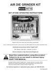
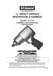
AIR/OVER HYDRAULIC JACK
20 TON
41487
ASSEMBLY AND OPERATING
INSTRUCTIONS
3491 Mission Oaks Blvd., Camarillo, CA 93011
Visit our Web site at http://www.harborfreight.com
Copyright © 1999 by Harbor Freight Tools. All rights reserved. No portion of this
manual or any artwork contained herein may be reproduced in any shape or
form without the express written consent of Harbor Freight Tools.
For technical questions and replacement parts, please call 1-800-444-3353
Specifications
ITEM
DESCRIPTION
Capacity
20 tons maximum
10-3/8 inch (minimum)
Height Movement
20-1/4 inch (maximum)
Ram
2.12 inch diameter; 6-1/2 inch length
Air Inlet Fitting
1/4 inch NPT
Weight
36.6 lbs.
Base Dimensions 7-1/2" x 4-3/4"
3/8 inch (O.D.) x 48 inches long with
Air Hose
crimped hose fittings
Air Pressure
90 - 125 PSI
Save This Manual
You will need the manual for the safety warnings and precautions, assembly instructions,
operating and maintenance procedures, parts list and diagram. Keep your invoice with this
manual. Write the invoice number on the inside of the front cover. Keep the manual and
invoice in a safe and dry place for future reference.
Safety Warnings and Precautions
WARNING: When using tool, basic safety precautions should always be followed to reduce
the risk of personal injury and damage to equipment.
Read all instructions before using this tool!
1.
Do not overload this equipment. Know the weight of the item being lifted.
2.
Use Jack for lifting only. Do not use this equipment for any other purpose.
Immediately after lifting, support the load with appropriate supporting equipment.
3.
Place Jack correctly. Only use this equipment on a surface that is stable, level, clean
and dry, and capable of sustaining the load.
4.
Stabilize load. Ensure that the load remains stable at all times. Do not move load
while on the Jack.
5.
Vehicle lifting. When lifting a vehicle, apply the emergency brake, and block all
wheels.
6.
Keep work area clean. Cluttered areas invite injuries.
7.
Observe work area conditions. Do not use machines or power tools in damp or wet
locations. Don’t expose to rain. Keep work area well lighted. Do not use electrically
powered tools in the presence of flammable gases or liquids.
8.
Keep children away. Children must never be allowed in the work area. Do not let
them handle machines, tools, or extension cords.
SKU 41487
Page 2
9.
Store idle equipment. When not in use, tools must be stored in a dry location to inhibit
rust. Always lock up tools and keep out of reach of children.
10. Do not force tool. It will do the job better and more safely at the rate for which it was
intended. Do not use inappropriate attachments in an attempt to exceed the tool
capacity.
11. Use the right tool for the job. Do not attempt to force a small tool or attachment to do
the work of a larger industrial tool. Do not use a tool for a purpose for which it was not
intended.
12. Dress properly. Do not wear loose clothing or jewelry as they can be caught in
moving parts. Protective, electrically non-conductive clothes and non-skid footwear
are recommended when working. Wear restrictive hair covering to contain long hair.
13. Use eye and ear protection. Always wear ANSI approved impact safety goggles.
Wear a full face shield if you are producing metal filings or wood chips. Wear an ANSI
approved dust mask or respirator when working around metal, wood, and chemical
dusts and mists.
14. Do not overreach. Keep proper footing and balance at all times. Do not reach over or
across running machines.
15. Maintain tools with care. Keep tools sharp and clean for better and safer
performance. Follow instructions for lubricating and changing accessories. Inspect tool
cords periodically and, if damaged, have them repaired by an authorized technician.
The handles must be kept clean, dry, and free from oil and grease at all times.
16. Remove adjusting keys and wrenches. Check that keys and adjusting wrenches
are removed from the tool or machine work surface before plugging it in.
17. Stay alert. Watch what you are doing, use common sense. Do not operate any tool
when you are tired.
18. Check for damaged parts. Before using any tool, any part that appears damaged
should be carefully checked to determine that it will operate properly and perform its
intended function. Check for alignment and binding of moving parts; any broken parts
or mounting fixtures; and any other condition that may affect proper operation. Any part
that is damaged should be properly repaired or replaced by a qualified technician. Do
not use the tool if any switch does not turn On and Off properly.
19. Replacement parts and accessories. When servicing, use only identical
replacement parts. Use of any other parts will void the warranty. Only use accessories
intended for use with this tool. Approved accessories are available from Harbor Freight
Tools.
20. Do not operate tool if under the influence of alcohol or drugs. Read warning
labels on prescriptions to determine if your judgment or reflexes are impaired while
taking drugs. If there is any doubt, do not operate the tool.
21. Not to be used for any aircraft purposes.
REV 02/04
SKU 41487
Page 3
Warning: The warnings, cautions, and instructions discussed in this instruction manual cannot cover all possible conditions and situations that
may occur. It must be understood by the operator that common sense and
caution are factors which cannot be built into this product, but must be
supplied by the operator.
Unpacking
When unpacking, check to make sure the following parts are included. If any parts are
missing or broken, please call Harbor Freight Tools at the number on the cover of this
manual as soon as possible.
Jack
Two-piece Handle
Hose and Fittings
Air Inlet Fitting
Assembly
1.
Screw the Connector (3) into the Air Pump (4) and tighten.
2.
Connect the Air Hose (2) to the Connector (3).
Tighten the Air Hose to prevent air loss.
3.
Connect the other end of the Air Hose to the Valve Body (1.6).
4.
Connect the two pipe Handles (5, 6) together.
Operation
Lifting
1.
Place the slotted end of the Lower Handle (6) over the Release Valve (18, 21).
Refer to the photo on the next page and the Assembly Drawing on the last page of this
manual.
2.
Turn the Valve Release screw clockwise until snug.
3.
Place the Jack into position under the load.
Caution: Follow all Safety and Precautions listed on pages 2 and 3.
4.
Adjust the Extension Screw (44) as needed.
Turn Counterclockwise to raise, clockwise to lower.
5.
Insert the big end of the Handle assembly into the Handle Sleeve (7).
6.
Connect the air supply hose lock fitting into the Air Inlet Fitting.
The Lever (1.13) should be Off (not in the locked position).
SKU 41487
Page 4
REV 05/04
7.
Press the Lever (1.13) to the On position and lock using the Lock Lever (1.17)
This provides a continuous air supply to the Air Pump (4).
8.
Raise the Jack by alternately lifting and lowering the Handle assembly.
Extension Screw (44)
Connector (3)
Handle fits in
Handle Sleeve
(7)
Release Valve (18, 21)
Air Hose (2)
Air Pump
(4)
Lever (1.13) and
Lever Lock (1.17)
Handle (5, 6)
Hose Connector (1.1)
Lowering
Caution: Avoid rapid descent of the load. Turn the Release Valve slowly.
1.
Release the Lock Lever (1.17) to stop air flow to the Air Pump (2).
2.
Remove air supply hose from the Air Inlet Fitting.
3.
Place the slotted end of the Handle (5, 6) assembly over the Release Valve (18, 21).
4.
Slowly and carefully lower the load by turning the Release Valve counterclockwise in
extremely small increments using only the Handle assembly (never your hand).
5.
Lower the Extension Screw (44) as needed by turning clockwise.
6.
Remove the Jack.
Maintenance
General Care
1.
Periodically lubricate the joints and Extension Screw (44) with a light oil as needed.
2.
Clean the outside of the Jack with a dry, clean cloth.
3.
If the Jack is exposed to moisture, wipe dry with a clean cloth and lubricate as noted
above.
4.
Store jack with Extension Screw (44) and Ram (48) fully collapsed.
SKU 41487
Page 5
REV 05/04
Purging Air from the Hydraulic System
Air bubbles can become trapped inside the hydraulic system thereby reducing the efficiency
of the Jack. Purge the air from the system if lift efficiency drops.
1.
Place the slotted end of the Handle (5, 6) assembly over the Valve Release screw (18,
21) and turn 1-1/2 turns counterclockwise.
2.
Remove the oil Filler Plug (23) on the side of the jack Reservoir (37) by gently pulling
and turning it.
3.
Rapidly pump the Handle assembly several times to purge the air from the hydraulic
system.
4.
Turn the Release Valve screw clockwise until snug using the Handle assembly.
5.
Top off jack Reservoir (37) as described below.
5.
Replace the Filler Plug (23).
Oil Replacement
1.
Place Jack in an upright position.
2.
Completely lower the Ram (48).
3.
Remove the Filler Plug (23).
4.
Fill with high-quality hydraulic jack oil to the lower rim of the fill hole.
5.
Purge air from the hydraulic system as previously described.
6.
Top off with more hydraulic oil.
7.
Replace Filler Plug (23).
PLEASE READ THE FOLLOWING CAREFULLY
THE MANUFACTURER AND/OR DISTRIBUTOR HAS PROVIDED THE PARTS
DIAGRAM IN THIS MANUAL AS A REFERENCE TOOL ONLY. NEITHER THE MANUFACTURER NOR DISTRIBUTOR MAKES ANY REPRESENTATION OR WARRANTY
OF ANY KIND TO THE BUYER THAT HE OR SHE IS QUALIFIED TO MAKE ANY REPAIRS TO THE PRODUCT OR THAT HE OR SHE IS QUALIFIED TO REPLACE ANY
PARTS OF THE PRODUCT. IN FACT, THE MANUFACTURER AND/OR DISTRIBUTOR
EXPRESSLY STATES THAT ALL REPAIRS AND PARTS REPLACEMENTS SHOULD
BE UNDERTAKEN BY CERTIFIED AND LICENSED TECHNICIANS AND NOT BY THE
BUYER. THE BUYER ASSUMES ALL RISK AND LIABILITY ARISING OUT OF HIS OR
HER REPAIRS TO THE ORIGINAL PRODUCT OR REPLACEMENT PARTS THERETO,
OR ARISING OUT OF HIS OR HER INSTALLATION OF REPLACEMENT PARTS
THERETO.
SKU 41487
Page 6
REV 05/04
Parts List
Part
Description
Qty.
Part
Description
Qty.
1.1
Hose Connector
1
18
Rlease Valve Screw
1
1.2
Connecting Nut
1
19
Release Valve Seal
1
1.3
Air Filter
1
20
Steel Ball 6.35
1
1.4
O-ring 18 X 2.4
1
21
Pin
1
1.5
Connector
1
22
Valve Spring
2
1.6
Valve Body
1
23
Filler Plug
1
1.7
Spring
1
24
Screw
2
1.8
Packing
1
25
Plug Screw
1
1.9
Throttle
1
26
Plunge Washer
1
1.10
O-ring 3 X 1.6
1
27
Overload Valve Screw
1
1.11
O-ring 18 X 2.4
1
28
Safety Valve Spring
1
1.12
Nut
1
29
Tapering Overload Valve
1
1.13
Lever
1
30
Filter Net
2
1.14
Lever Ring
1
31
Spring Washer 8
2
1.15
Hose Connector
1
32
Nut 8
2
1.16
Hose Band
2
33
Bolt M8 X 3.5
2
1.17
Lock Lever
1
34
Base
1
2
Air Hose
1
35
Plug Screw
4
3
Connector
1
36
Cylinder Bottom Seal
1
4
Air Pump
1
37
Reservoir
1
5
Handle, Upper
1
38
Packing
1
6
Handle, Lower
1
39
Cylinder
1
7
Handle Sleeve
1
40
Steel Ball Retainer
2
8
Shaft Pin
3
41
Cylinder Top Seal
1
9
Cotter Pin
3
42
0-ring
1
10
Pump Plunger
1
43
Top Nut
1
11
Pump Plunger Retainer
1
44
Extension Screw
1
12
O-ring
1
45
0-ring
1
13
Dust-Resistant Ring
1
46
0-ring Returner
1
14
Pump Reservoir
1
47
Ram Header
1
15
Copper Washer
1
48
Ram
1
16
Steel Ball 6
6
49
Spring
2
17
Plunger Connecting Rod
1
50
Spring Plate
1
SKU 41487
Page 7
REV 05/04
Assembly Drawing
SKU 41487
Page 8
REV 05/04