1
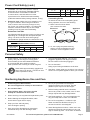
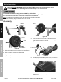
Owner’s Manual & Safety Instructions
Save This Manual Keep this manual for the safety warnings and precautions, assembly,
operating, inspection, maintenance and cleaning procedures. Write the product’s serial number in the
back of the manual near the assembly diagram (or month and year of purchase if product has no number).
Keep this manual and the receipt in a safe and dry place for future reference.
REV 14k
Visit our website at: http://www.harborfreight.com
Email our technical support at: [email protected]
When unpacking, make sure that the product is intact
and undamaged. If any parts are missing or broken,
please call 1-888-866-5797 as soon as possible.
Copyright© 2012 by Harbor Freight Tools®. All rights reserved.
No portion of this manual or any artwork contained herein may be reproduced in
any shape or form without the express written consent of Harbor Freight Tools.
Diagrams within this manual may not be drawn proportionally. Due to continuing
improvements, actual product may differ slightly from the product described herein.
Tools required for assembly and service may not be included.
Read this material before using this product.
Failure to do so can result in serious injury.
SAVE THIS MANUAL.
Table of Contents
SAFETY
Safety.......................................................... 2
Maintenance................................................ 9
Specifications.............................................. 5
Setup........................................................... 5
Operation..................................................... 8
Parts List and Diagram............................... 10
Warranty..................................................... 12
WARNING SYMBOLS AND DEFINITIONS
This is the safety alert symbol. It is used to alert you to potential personal injury hazards.
Obey all safety messages that follow this symbol to avoid possible injury or death.
Indicates a hazardous situation which, if not avoided,
will result in death or serious injury.
SETUP
Indicates a hazardous situation which, if not avoided,
could result in death or serious injury.
Indicates a hazardous situation which, if not avoided,
could result in minor or moderate injury.
Addresses practices not related to personal injury.
IMPORTANT SAFETY INSTRUCTIONS
OPERATION
When using electric gardening appliances, basic safety precautions should always be followed
to reduce the risk of fire, electric shock, and personal injury, including the following:
READ ALL INSTRUCTIONS
Power Cord Safety
WARNING! - To reduce the risk of electric
shock, use only with an extension cord
intended for outdoor use, such as an
extension cord of cord type
SW-A, SOW-A, STW-A, STOW-A, SJW-A,
SJOW-A, SJTW-A. or SJTOW-A.
MAINTENANCE
1. Ground Fault Circuit Interrupter (GFCI) protection
should be provided on the circuit(s) or outlet(s) to
be used for the gardening appliance. Receptacles
are available having built-in GFCI protection
and may be used for this measure of safety.
2. Do not Abuse Cord - Do not carry appliance by
cord or yank it to disconnect from receptacle.
Keep cord from heat, oil, and sharp edges.
Page 2
3. To reduce the risk of electric shock, this appliance
has a polarized plug (one blade is wider than
the other) and will require the use of a polarized
extension cord. The appliance plug will fit
into a polarized extension cord only one way.
If the plug does not fit fully into the extension cord,
reverse the plug. If the plug still does not fit, obtain
a correct polarized extension cord. A polarized
extension cord will require the use of a polarized
wall outlet. This plug will fit into the polarized wall
outlet only one way. If the plug does not fit fully
into the wall outlet, reverse the plug. If the plug
still does not fit, contact a qualified electrician to
install the proper wall outlet. Do not change the
equipment plug, extension cord receptacle, or
extension cord plug in any way. This design is
referred to as double-insulated, indicated by
.
For technical questions, please call 1-888-866-5797.
Item 69293
Power Cord Safety (cont.)
Extension Cord Size
18
16
10 – 12
16
16
12 – 16
14
12
12
14
12
Not recommended
Connecting Cords
To reduce the risk of the cords pulling apart
during operation, do one of the following:
a. Make a knot as shown below
then connect the cords:
Extension
Cord
The following table shows the correct cord size to use
depending on cord length and nameplate ampere
rating. If in doubt, use the next heavier gauge.
The smaller the gauge number, the heavier the cord.
Appliance
Cord
2
TABLE A – MINIMUM WIRE GAUGE FOR
EXTENSION CORDS (120 VOLT)
Ampere Rating
14
SAFETY
5. Extension Cord - Make sure your extension cord
is in good condition. When using an extension
cord, be sure to use one heavy enough to carry
the current your product will draw. An undersized
extension cord will cause a drop in line voltage
resulting in loss of power and overheating.
6 – 10
SETUP
4. WARNING: The cord of this product contains
lead and/or di (2-ethylhexyl) phthalate (DEHP),
chemicals known to the State of California
to cause cancer, and birth defects or other
reproductive harm. Wash hands after handling.
(California Health & Safety Code § 25249.5, et seq.)
1
EXTENSION CORD LENGTH
(at full load)
25′
50′
100′
150′
0–6
18
16
16
14
b. Or, use a plug-receptacle retaining
strap or connector designed to hold
extension cords to appliance cords.
1. Dress Properly - Do not wear loose clothing or
jewelry. They can be caught in moving parts.
Use of rubber gloves and substantial footwear
is recommended when working outdoors.
Wear protective hair covering to contain long hair.
3. Avoid Unintentional Starting - Do not carry
plugged-in appliance with finger on switch.
Be sure switch is off when plugging in.
2.
5. Stay Alert - Watch what you are doing. Use common
sense. Do not operate appliance when you are tired.
Wear ANSI-approved safety goggles and
heavy-duty work gloves. Use face or dust
mask if operation is dusty.
4. Do not Overreach Keep proper footing and balance at all times.
OPERATION
Personal Safety
Gardening Appliance Use and Care
2. Do not Use In Rain.
3. Keep Children Away - All visitors should
be kept at a distance from work area.
4. When servicing use only identical replacement parts.
5. Before Starting the Chipper/Shredder, make
sure that the hopper inlet is empty.
6. Keep your face and body away
from the Hopper opening.
7. Stay clear of the discharge area. Keep body
and hands away from the discharge chute.
Item 69293
8. Do not put your hands into the hopper
opening while the unit is running. Use the
paddle to push objects into the hopper.
9. Before feeding material into the shredder,
remove any metal, rocks, bottles, cans or other
foreign objects that may damage blades.
10. Use Right Appliance - Do not use appliance for
any job except that for which it is intended.
11. Do not Force Appliance - It will do the job
better and with less likelihood of injury at
the rate for which it was designed.
12. Store Idle Appliances Indoors - When not in use,
appliances should be stored indoors in dry, and
high or locked-up place - out of reach of children.
For technical questions, please call 1-888-866-5797.
Page 3
MAINTENANCE
1. Avoid Dangerous Environment Do not use appliances in damp or wet locations.
SAFETY
13. Maintain Appliance With Care - Keep cutting edge
sharp and clean for best performance and to reduce
the risk of injury. Follow instructions for lubricating
and changing accessories. Inspect appliance cord
periodically, and if damaged, have it repaired by
an authorized service facility. Inspect extension
cords periodically and replace if damaged. Keep
handles dry, clean, and free from oil and grease.
14. Check Damaged Parts - Before further use of the
appliance, a guard or other part that is damaged
should be carefully checked to determine that it will
operate properly and perform its intended function.
Check for alignment of moving parts, binding of
moving parts, breakage of parts, mounting, and any
other condition that may affect its operation. A guard
or other part that is damaged should be properly
repaired or replaced by a qualified technician
unless indicated elsewhere in this manual.
15. Disconnect Appliance - Disconnect the
appliance from the power supply when not
in use, before servicing, when changing
accessories such as blades, and the like.
16. Keep guards in place and in working order.
17. Keep blades sharp.
18. Keep clear of intake and discharge chute.
Use included push stick. Unplug unit and
allow it to stop before unclogging.
SETUP
General Safety
1. Do not use appliance for other than intended use.
2. Maintain labels and nameplates on the appliance.
These carry important safety information.
If unreadable or missing, contact
Harbor Freight Tools for a replacement.
3. The warnings, precautions, and instructions
discussed in this instruction manual cannot
cover all possible conditions and situations
that may occur. It must be understood by the
operator that common sense and caution are
factors which cannot be built into this product,
but must be supplied by the operator.
SAVE THESE INSTRUCTIONS.
OPERATION
MAINTENANCE
Page 4
For technical questions, please call 1-888-866-5797.
Item 69293
Electrical Rating
120VAC / 60Hz / 14A
Blade Speed
4,300 RPM
Blade Diameter
7"
Maximum Limb Capacity
1-1/2" Diameter
SAFETY
Specifications
MAINTENANCE
OPERATION
SETUP
215530
Item 69293
For technical questions, please call 1-888-866-5797.
Page 5
Set Up Instructions
Read the ENTIRE IMPORTANT SAFETY INSTRUCTIONS section at the beginning of this manual
including all text under subheadings therein before set up or use of this product.
SAFETY
TO PREVENT SERIOUS INJURY FROM ACCIDENTAL OPERATION:
Turn the Power Switch of the appliance to its “OFF” position and unplug the appliance
from its electrical outlet before assembling or making any adjustments.
Note: For additional information regarding the parts listed in the following pages,
refer to the Assembly Diagram near the end of this manual.
Assembly
Bushing
Axle
Wheel
Cover
SETUP
Lower Frame
Figure B
Lock Nut
Wheel
5. Press the Wheel Covers onto the Wheels, over the
Lock Nuts, using a rubber mallet (sold separately) to
lightly tap them in place if needed.
OPERATION
Washer
Base
Figure A
Lower Frame
1. Slide the Axle through the holes on the Lower Frame.
2. Slide a Bearing, a Bushing, a Wheel and
a Washer onto one end of the Axle.
3. Tighten in place with a Lock Nut.
4. Repeat steps 2 and 3 on the other end of the Axle.
Slots
Figure C
6. Turn the Chipper/Shredder upside down and slide the
Lower Frame ends into the slots on the Base.
MAINTENANCE
Screws and Washers
Figure D
7. Align the holes and secure in place with four Washers
and Screws.
Page 6
For technical questions, please call 1-888-866-5797.
Item 69293
Functions
SAFETY
Hopper
Locking Knob
Control Panel
Reset
Button
Power Switch
Switch Key
SETUP
Hopper
Control Panel
OPERATION
Base
Lower Frame
Item 69293
For technical questions, please call 1-888-866-5797.
MAINTENANCE
Figure E
Page 7
Operating Instructions
Read the ENTIRE IMPORTANT SAFETY INFORMATION section at the beginning of this manual
including all text under subheadings therein before set up or use of this product.
SAFETY
Operation
1. Before operating the Chipper/Shredder,
put on ANSI-approved safety goggles and
other safety gear. Safety goggles and
other safety gear are sold separately.
SETUP
2. If an extension cord is used, ensure that it is an
outdoor type extension cord and that it is the correct
design to accept this appliance’s plug.
WARNING!
TO PREVENT ELECTRIC SHOCK AND
SERIOUS PERSONAL INJURY:
The extension cord must remain
secured to the appliance’s plug.
Secure the extension cord by either using the knot
method explained in the safety warning section, or
by using a device designed specifically for retaining
the extension cord (sold separately).
WARNING! Keep a safe distance from the
Hopper opening. Longer material can lash
out when being pulled in by the blades.
WARNING! Keep clear of intake and discharge
chute. Use included push stick. Unplug unit
and allow it to stop before unclogging.
CAUTION! Keep the ventilation slots clear
while working to avoid overheating.
10. Do not shred soft, damp material such as kitchen
waste as it may clog the Chipper/Shredder. Let damp
garden waste dry for a few days before shredding.
11. Remove soil and rocks from roots before
inserting them into the Chipper/Shredder.
3. Check that the Power Switch is OFF.
4. Check that the feed inlet is empty.
5. Check that the Hopper is securely closed and that
the Hopper Locking Knob is turned fully clockwise.
Note: The Chipper/Shredder will not run if the Hopper is
open, not fitted well, or the Hopper Locking Knob is loose.
OPERATION
6. Insert the Switch Key.
7. Plug the Power Cord into a 120VAC/60Hz outlet.
8. Turn on the Power Switch.
12. Use the Push Stick to feed leaves and
other small material into the Hopper.
13. Feed material into the Chipper/Shredder at
the rate that the machine pulls the material.
Do not force material into the machine.
14. Set aside a few dry branches, then feed them into
the machine when finished, to help clean the unit.
15. Wait for all material to pass through the Chipper/
Shredder before turning the unit off.
MAINTENANCE
9. Hold branches and feed them into the hopper.
Release the branches when they begin to pull into
the hopper.
16. To prevent accidents, turn the power off,
remove the Switch Key and disconnect the
power supply after use. Clean, then store the
appliance indoors out of children’s reach.
Overload Protection
This Chipper/Shredder is equipped with an overload protection system. If the unit clogs
while running, the overload protection system will shut the power off. Wait at least one
minute before restarting. Press the Reset Button then turn the Power Switch on.
Page 8
For technical questions, please call 1-888-866-5797.
Item 69293
Maintenance and Servicing
SAFETY
Procedures not specifically explained in this manual
must be performed only by a qualified technician.
TO PREVENT SERIOUS INJURY FROM ACCIDENTAL OPERATION OR ELECTRIC SHOCK:
Turn the Power Switch of the appliance to its “OFF” position and unplug the appliance from its
electrical outlet before performing any inspection, maintenance, or cleaning procedures.
TO PREVENT SERIOUS INJURY FROM TOOL FAILURE:
Do not use damaged equipment. If abnormal noise or vibration occurs,
have the problem corrected before further use.
Cleaning, Maintenance
• loose hardware,
• misalignment or binding of moving parts,
• cracked or broken parts,
• damaged electrical wiring, and
• any other condition that may
affect its safe operation.
2. AFTER USE, clean external surfaces of
the appliance with clean, moist cloth.
3. Replace or sharpen the Blades
as needed. (See below.)
SETUP
1. BEFORE EACH USE, inspect the general
condition of the tool. Check for:
4. If the motor turns but the appliance does not
function, the belt may be broken. Have the
belt replaced by a qualified technician.
5.
WARNING! If the supply cord of this
appliance is damaged, it must be replaced
only by a qualified service technician.
1. Turn the Hopper Locking Knob
counterclockwise and open the Hopper.
2. Clean the cutting Blades and discharge
area and remove wood sticks or objects
that may clog the Blades.
3. Check the Blades for damage and replace if needed.
4. Return the Hopper to its upright position
and tighten in place with the Locking
Knob after cleaning the interior.
5. Use a warm damp cloth and a soft brush to clean
the exterior of the Chipper/Shredder. Do not spray
water or use detergents on the Chipper/Shredder.
6. Check that the ventilation slots are clean.
OPERATION
Cleaning the Chipper/Shredder
Replacing the Blades
Screws
Blade
Figure F
Item 69293
1. Access the Blades by opening the Hopper.
2. Align the slots on the Cutter Head and main
body and insert a screwdriver or other metal
rod (sold separately) to prevent the unit from
rotating while changing the Blades.
3. Unthread the two screws holding a Blade
and carefully remove the Blade.
4. Either reverse the Blade with the sharp edge in
the cutting position, have the blade professionally
sharpened/honed, or insert a new Blade.
5. Secure in place with the screws. Repeat
with the other Blade at the same time.
For technical questions, please call 1-888-866-5797.
Page 9
MAINTENANCE
The reversible Blades are attached to the
Cutter Head with two screws.
Blade
Rod inserted
in slots
Parts List and Diagram
PLEASE READ THE FOLLOWING CAREFULLY
SAFETY
THE MANUFACTURER AND/OR DISTRIBUTOR HAS PROVIDED THE PARTS LIST AND ASSEMBLY DIAGRAM
IN THIS MANUAL AS A REFERENCE TOOL ONLY. NEITHER THE MANUFACTURER OR DISTRIBUTOR
MAKES ANY REPRESENTATION OR WARRANTY OF ANY KIND TO THE BUYER THAT HE OR SHE IS
QUALIFIED TO MAKE ANY REPAIRS TO THE PRODUCT, OR THAT HE OR SHE IS QUALIFIED TO REPLACE
ANY PARTS OF THE PRODUCT. IN FACT, THE MANUFACTURER AND/OR DISTRIBUTOR EXPRESSLY
STATES THAT ALL REPAIRS AND PARTS REPLACEMENTS SHOULD BE UNDERTAKEN BY CERTIFIED AND
LICENSED TECHNICIANS, AND NOT BY THE BUYER. THE BUYER ASSUMES ALL RISK AND LIABILITY
ARISING OUT OF HIS OR HER REPAIRS TO THE ORIGINAL PRODUCT OR REPLACEMENT PARTS
THERETO, OR ARISING OUT OF HIS OR HER INSTALLATION OF REPLACEMENT PARTS THERETO.
Parts List
Part
SETUP
OPERATION
MAINTENANCE
1
2
3
4
5
6
7
8
9
10
11
12
13
14
15
16
17
18
19
20
21
22
23
24
25
26
27
28
29
30
31
32
33
34
35
36
37
38
Page 10
Description
Push Stick
Hopper
Safety Guard Board
Batten
Self Tapping Screw 4*18
Upper Fuselage
Self Tapping Screw 5*20
Switch Bolt
Hopper Locking Knob
Washer
Base Fuselage
Split Pin
Washer
Hex Screw M8
Internal Washer
Press Board
Countersunk Hex Screw M10
Blade
Cutter Head
Driving Block
Spring Washer
Splash Guard
Pull Pole
Self Lock Nut
Slowdown Upper Cover Box
Belt
Self Tapping Screw 4*14
Impeller
Big Pulley
Eccentric Wheel
Small Pulley
Slowdown Base Cover Box
Stator Screw M4
Flat Washer
Motor Front Frame
Cover
Stator
Rotor
Qty
1
1
1
1
15
1
31
1
1
4
1
1
9
1
1
1
4
2
1
1
10
1
1
4
1
1
7
1
1
1
1
1
2
2
1
1
1
1
Part
39
40
41
42
43
44
45
46
47
48
49
50
51
52
53
54
55
56
57
58
59
60
61
62
63
64
65
66
67
68
69
70
71
72
73
74
75
Description
Bearing 627Z
Motor Backward Frame
Hex Nut M4
Brush
Brush Holder
Brush Holder Press Board
Self Tapping Screw 3*8
Machine Plate
Fix Nut
Safety Switch
Switch Fix Board
Machine Screw M4*40
Dust Shield
Self Tapping Screw 4*16
Soft Startup
Motor Box
Power Switch
Reset Button
Cable Cover
Cable Press Board
Power Cord
Cable Press Board
Pin
Lower Frame
Axle
Bearing
Bushing
Wheel
Self Lock Nut
Wheel Cover
Wire
Wire
Wire
Push Stick Clip
Wrench
Hex Key
Screen
For technical questions, please call 1-888-866-5797.
Qty
0
1
2
2
2
2
4
1
1
1
1
2
1
12
1
1
1
1
1
1
1
1
2
1
1
2
2
2
2
2
1
1
1
1
1
1
1
Item 69293
MAINTENANCE
OPERATION
SETUP
SAFETY
Assembly Diagram
Record Product’s Serial Number Here:
Note: If product has no serial number, record month and year of purchase instead.
Note: Some parts are listed and shown for illustration purposes only,
and are not available individually as replacement parts.
Item 69293
For technical questions, please call 1-888-866-5797.
Page 11
Limited 90 Day Warranty
Harbor Freight Tools Co. makes every effort to assure that its products meet high quality and durability standards,
and warrants to the original purchaser that this product is free from defects in materials and workmanship for the
period of 90 days from the date of purchase. This warranty does not apply to damage due directly or indirectly,
to misuse, abuse, negligence or accidents, repairs or alterations outside our facilities, criminal activity, improper
installation, normal wear and tear, or to lack of maintenance. We shall in no event be liable for death, injuries
to persons or property, or for incidental, contingent, special or consequential damages arising from the use of
our product. Some states do not allow the exclusion or limitation of incidental or consequential damages, so the
above limitation of exclusion may not apply to you. THIS WARRANTY IS EXPRESSLY IN LIEU OF ALL OTHER
WARRANTIES, EXPRESS OR IMPLIED, INCLUDING THE WARRANTIES OF MERCHANTABILITY AND FITNESS.
To take advantage of this warranty, the product or part must be returned to us with transportation charges
prepaid. Proof of purchase date and an explanation of the complaint must accompany the merchandise.
If our inspection verifies the defect, we will either repair or replace the product at our election or we may
elect to refund the purchase price if we cannot readily and quickly provide you with a replacement. We will
return repaired products at our expense, but if we determine there is no defect, or that the defect resulted
from causes not within the scope of our warranty, then you must bear the cost of returning the product.
This warranty gives you specific legal rights and you may also have other rights which vary from state to state.
3491 Mission Oaks Blvd. • PO Box 6009 • Camarillo, CA 93011 • 1-888-866-5797