1
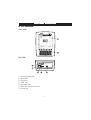
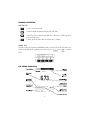
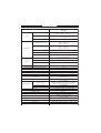
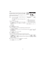
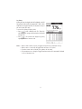
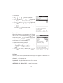
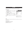
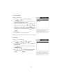
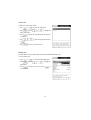
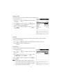
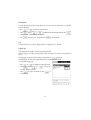
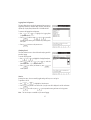
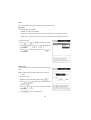
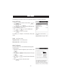
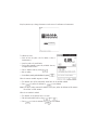
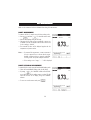
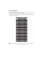
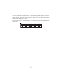
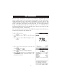
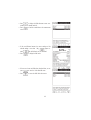
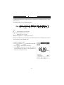
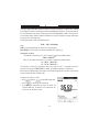
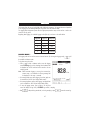
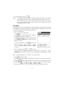
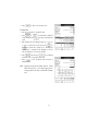
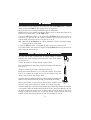
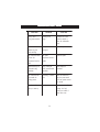
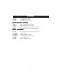
Instruction Manual
HI 4421
DO/BOD/OUR/SOUR/Temperature
Bench Meter
w w w. h a n n a i n s t . c o m
1
Dear Customer,
Thank you for choosing a Hanna Instruments product. This manual will provide you with the necessary
information for correct use of the instrument.
Please read this instruction manual carefully before using the instrument.
If you need additional technical information, do not hesitate to e-mail us at [email protected] or see the
back side of this manual for our worldwide sales and technical service contacts.
These instruments are in compliance with
directives.
WARRANTY
HI 4421 is warranted for two years against defects in workmanship and materials when used for their
intended purpose and maintained according to instructions. The probe is guaranteed for six months. This
warranty is limited to repair or replacement free of charge.
Damage due to accidents, misuse, tampering or lack of prescribed maintenance is not covered.
If service is required, contact the dealer from whom you purchased the instrument. If under warranty, report
the model number, date of purchase, serial number and the nature of the failure. If the repair is not covered
by the warranty, you will be notified of the charges incurred. If the instrument is to be returned to Hanna
Instruments, first obtain a Returned Goods Authorization number from the Technical Service Department and
then send it with shipping costs prepaid. When shipping any instrument, make sure it is properly packed for
complete protection.
To validate your warranty, fill out and return the enclosed warranty card within 14 days from the date of
purchase.
2
TABLE OF CONTENTS
WARRANTY ...................................................................................................................................... 2
PRELIMINARY EXAMINATION .............................................................................................................. 4
GENERAL DESCRIPTION ...................................................................................................................... 4
FUNCTIONAL DESCRIPTION ................................................................................................................ 5
SPECIFICATIONS ................................................................................................................................ 7
OPERATIONAL GUIDE ....................................................................................................................... 8
DISPLAYING MODES ......................................................................................................................... 9
SYSTEM SETUP............................................................................................................................... 12
DO SETUP......................................................................................................................... 18
BOD SETUP............................................................................................................................. 29
OUR SETUP.............................................................................................................. 31
SOUR SETUP.............................................................................................................. 33
DO CALIBRATION.............................................................................................................. 35
PRESSURE CALIBRATION.............................................................................................................. 37
DO MEASUREMENT.............................................................................................................. 38
BOD MEASUREMENT.............................................................................................................. 42
OUR MEASUREMENT ............................................................................................... 45
SOUR MEASUREMENT.............................................................................................................. 46
LOGGING ....................................................................................................................................... 47
PC INTERFACE .................................................................................................................................... 52
PROBE CONDITIONING & MAINTENANCE ..................................................................................... 52
TROUBLESHOOTING GUIDE .............................................................................................................. 53
ACCESSORIES .................................................................................................................................. 54
3
PRELIMINARY EXAMINATION
Remove the instrument from the packing material and examine it carefully to make sure that no damage has
occurred during shipping. If there is any damage, notify your dealer or the nearest Hanna Service Center.
The meter is supplied complete with:
• HI 76408 DO probe for laboratory use with built-in temperature sensor
• HI 7041S Electrolyte solution (30 mL)
• HI 76407A Membrane caps (2 pcs)
• HI 76404N Electrode Holder
• 12Vdc Power Adapter
• Instruction Manual
HI 4421 is supplied with 12 Vdc/230 Vac adapter.
HI 4421-01 is supplied with 12 Vdc/115 Vac adapter.
Note:
Save all packing material until you are sure that the instrument works properly. Any defective item
must be returned in the original packing with the supplied accessories.
GENERAL DESCRIPTION
HI 4421 is a professional bench meter with color graphic LCD for DO, BOD, OUR, SOUR and temperature
measurements.
The display viewing modes are: Basic information only, GLP information, Graph and Log History mode.
The main features of the instruments are:
• One input channel;
• Six measurement parameters: DO, BOD, OUR, SOUR, pressure and temperature;
• Automatic or user standard DO calibration;
• AutoHold feature to freeze the stable reading on the LCD (DO only);
• Two selectable alarm limits (for DO, BOD, OUR, SOUR);
• Three selectable logging modes: Automatic logging, Log on demand (manual logging) and AutoHold logging
mode (DO only);
• Up to 100 logging lots for automatic or manual modes, up to 200 OUR and SOUR reports and up to 200 BOD
method information entries;
• Selectable area and settable sampling period feature for automatic logging;
• GLP feature;
• Online and offline graph;
• User-friendly interface on large color graphic LCD (240x320 pixels);
• Opto-isolated PC interface via RS232 respectively USB.
4
FUNCTIONAL DESCRIPTION
HI 4421 DESCRIPTION
FRONT PANEL
REAR PANEL
1)
2)
3)
4)
5)
6)
7)
Liquid Crystal Display (LCD)
Main Keyboard
USB connector
ON/OFF switch
Power adapter socket
RS232 serial communication connector
DO probe input
5
KEYBOARD DESCRIPTION
FUNCTION KEYS
To enter / exit calibration mode.
To select the desired measurement mode: DO, BOD, OUR, SOUR.
To enter Setup (System Setup, DO Setup, BOD Setup , OUR Setup or SOUR Setup) and to
access Log Recall function.
To obtain general informations about the selected option / operation.
VIRTUAL KEYS
The upper row keys are assigned to the virtual keys placed on the bottom of the LCD, which allow you to
and
in Measure
perform the displayed function, depending on the current menu (e.g.
mode).
LCD GENERAL DESCRIPTION
6
SPECIFICATIONS
HI 4421
Ra n g e
0.00 to 90.00 p p m
0.0 to 600.0 % sa tu ra tion
Resolu tion
0.01 p p m
0.1 % sa tu ra tion
Accu ra cy
±1.5% of rea d in g ±1 d ig it
Mea su rem en t ra n g e
-20.0 to 120.0 °C
-4.0 to 248.0 °F
253.1 to 393.1 K
D O com p en sa tion ra n g e
0.0 to 50.0 °C
32.0 to 122.0 °F
237.1 to 323.1 K
Resolu tion
0.1 °C, °F, K
Accu ra cy
±0.2 °C, °F, K
DO
Tem p era tu re
Ba rom etric
p ressu re
Un its
°C, °F, K
Ra n g e
450 to 850 m m Hg
560 to 1133 m Ba r
Resolu tion
1 m m Hg
Accu ra cy
±3 m m Hg + 1 lea st sig n ifica n t d ig it
Ra n g e
0 to 45 p p t, g /L
Sa lin ity com p .
BOD (Bioch em ica l Oxyg en D em a n d )
Yes
OUR (Oxig en Up ta ke Ra te)
Yes
SOUR (Sp ecific Oxig en Up ta ke Ra te)
Yes
K eyb oa rd
8 keys (4 virtu a l keys)
Prob e
Pola rog ra p h ic with tem p era tu re b u ilt-in
PC in terfa ce
Op to-isola ted
RS232, USB
E xtern a l D a ta Stora g e
No
u p to 100 lots
10000 sa m p les/lot for Au tom a tic L og g in g
5000 sa m p les/lot for Ma n u a l L og g in g
Record sa m p les
L og g in g Fea tu res
L og g in g in terva l
1 to 300000 sec
Typ e
Ma n u a l, Au tom a tic
GL P
L a st ca lib ra tion d a ta , ca lib ra tion in fo
Ba ck lig h t Sa ver
Yes (a u tom a tic)
Au toE n d m od e
D O on ly
Ala rm (D O, BOD , OUR, SOUR)
Yes (In sid e/Ou tsid e lim its)
Ca lib ra tion
Au tom a tic / User sta n d a rd
(1 or 2 p oin ts)
Ca lib ra tion sta n d a rd
0 a n d 100% sa tu ra tion
L CD
Color Gra p h ic L CD 240 x 340 p ixels
D im en sion s
160 x 231 x 94 m m (6.3 x 9.1 x 3.7 ")
Weig h t
1.2 K g (2.6 lb )
7
OPERATIONAL GUIDE
POWER CONNECTION
Plug the 12 Vdc adapter into the power supply socket.
Note: These instruments use non volatile memory to retain the meter settings, even when unplugged.
PROBE CONNECTION
For DO, BOD, OUR or SOUR measurements connect a DO probe to the DIN connector located on the rear panel
of the instrument.
INSTRUMENT START UP
• Turn the instrument on from the power switch located on the rear panel of the instrument.
• Please wait until the instrument finishes the initialization process.
Note: It is normal for the loading process to take a few seconds. If the instrument doesn’t display the next
screen, restart the meter using the power switch. If the problem persists, contact your dealer.
8
DISPLAYING MODES
For each measurement mode (DO, BOD, OUR or SOUR) the following display configurations are available:
Basic, Good Laboratory Practice (GLP), Graph and Log History.
Basic
Accessing this option, the measured value and its units are
displayed on the LCD, along with the temperature value, temperature compensation mode, pressure value, pressure compensation
mode and minimal GLP data.
To choose the Basic displaying mode:
• Press
while in Measure mode. The “Choose Display
Configuration” message will be displayed in the Reminder
messages area.
• Press
. The instrument will display the basic information for the selected measurement mode.
GLP
Accessing this option, a detailed GLP data will be displayed on the
LCD for DO measure modes: Last Calibration Date and Time,
Sample ID, Buffer Value, Pressure Value, Salinity Value, Temperature Value, Temperature Compensation, the Date and Time.
To access the GLP displaying mode:
• Press
while in Measure mode. The “Choose Display
Configuration” message will be displayed in the Reminder
messages area.
• Press
data.
. The instrument will display the detailed GLP
9
Graph
Accessing this option, the online graph with currently logged
values (DO, BOD, OUR or SOUR vs. Seconds) could be displayed.
If there is no active log, the previously logged data for the
selected parameter will be plotted.
Notes: • If no data were logged, the graph displaying mode
will not be accessible.
• If no automatic log is saved, the offline graph will not
be available.
To access the offline / online graph:
• Press
while in Measure mode. The “Choose Display
Configuration” message will be displayed in the Reminder
messages area.
• Press
.
When the online graph is displayed:
• Use
and
to move the graph along the horizontal (Time) axis.
• Press
to access the zoom menu for the vertical (Parameter) axis. Use
vertical axis zooming.
or
for
to return to the main menu.
• Press
When the offline graph is displayed:
• Use the arrow keys to move the graph along the horizontal and vertical axes.
• Press
to access the zoom menu for the horizontal and vertical axes. Use
/
/
to zoom the selected axis.
to switch between the active zooming axes. Press
Note: While in zoom graph menu the
• Press
key is not accessible.
to return to the main menu.
10
or
or
/
Log History
Accessing this option, last logged records will be displayed on the LCD.
The log history list also contains the appropriate DO / BOD / OUR /
SOUR values, the logged temperature, the temperature source, as
well as the records time stamp.
To access the Log History displaying mode:
• Press
while in Measure mode. The “Choose Display Configuration” message will be displayed in the Reminder
messages area.
• Press
. The instrument will display the log history
regarding the selected measure mode.
Notes: •
•
•
•
When an alarm condition is active, the logged records will have an exclamation mark (!).
When a meter is in auto-hold, the logged records will have an “H” symbol.
If another measure mode is selected, the Log History will be cleared.
If the temperature unit is changed, all logged temperature values will be automatically displayed
in the new temperature unit.
11
SYSTEM SETUP
The System Setup menu allows the user to customize the user interface, consult the meter information, set the
external serial communication interface and to restore the manufacturer settings.
Accessing System Setup
• Press
while in Measure mode.
. The system setup options will be displayed
• Press
on the LCD.
To access a System Setup option:
• Use
• Press
or
to highlight the desired option.
to access the selected option.
The following is a detailed description of the System Setup option
screen.
Beeper
This option allows the user to enable or disable the beeper. When the beeper is enabled, a specific beep will
be heard when the reading becomes stable, when an alarm condition is reached, when pressing a key or if
a wrong key is pressed.
Stability Indicator
When the reading becomes stable, the instrument delivers a medium beep only if this option is activated, along
with the “Stable” indicator on the LCD.
Alarm
If this option is activated, a continuous double beep will be heard each time the set limits in Measure mode are
exceeded, along with the “Alarm” indicator on the LCD.
Key Pressed
If this option is activated, a short beep will be heard each time a valid key is pressed.
Wrong Key
If this option is activated, a long beep will be heard when an incorrect key is pressed.
12
To set the Beeper:
• Use
or
to select the Beeper option.
• Press
and use
or
to highlight the
desired beeper associated event you want to modify.
and use
• Press
beeper status option.
• Press
or
to highlight the
to confirm your selection and return to the Beeper
menu or press
to return without changing.
Saving Confirmation
When enabling this option, a prompt will appear on the LCD alerting
, exiting
the user to save the modified values by pressing
without saving by pressing
or canceling the saving operation
and return to the editing mode by pressing
modified values will be saved automatically.
To enabled /disabled the saving confirmation:
• Use
• Press
/ disabled.
or
and use
. If disabled, the
to select the Saving Confirmation option.
or
to choose enabled
to confirm your selection or press
• Press
cancel operation.
to
GLP Data
This option allows the user to set general information which will appear in the log reports. The edited text can have
max 10 characters.
Operator ID – edit the operator’s name.
Instrument ID – edit an identification name / number for the instrument.
Company Name – edit the company name.
Additional Info 1 & Additional Info 2 – for general purpose notations.
13
To set the GLP data:
• Use
or
to select the GLP Data option.
and use
• Press
desired option.
or
to highlight the
• Press
to edit the desired information. The Text Editor menu
will be displayed on the LCD.
and
to
• Enter the desired information by using
highlight the desired character. It is also possible to delete the last
character by positioning the cursor on the Backspace character ( )
.
and pressing
• Press
to return to the GLP Data menu. If the Saving
Confirmation is enabled, press
to accept the modified option,
to escape without saving or
to return to the editing mode. Otherwise, the modified options are saved automatically.
Date & Time
This option allows the user to set the current date & time and the format in which they appear. These parameters
will be displayed on the Measure screens and also when storing measured data.
Set Date and Time
This option allows you to set the current date (year / month / day) and time (hour / minute / second).
Notes: • Only years starting with 2000 are accepted.
• The time is set using the selected time format. For 12 Hour time format only, the AM / PM can
or
.
also be selected with
Set Time Format
This option allows you to choose between 12 Hour (AM / PM) time format and 24 Hour time format from the
displayed pop-up box.
Set Date Format
This option allows you to choose the desired date format from the available formats: DD/MM/YYYY; MM/DD/YYYY;
YYYY/MM/DD; Mon DD, YYYY; DD-MM-YYYY and YYYY-Mon-DD.
To set the Date & Time:
14
• Use
to select the Date & Time option.
or
• Press
and use
or
desired option you want to modify.
to highlight the
to confirm your selection. Use
• Press
and then use
and
to modify the value with
(for Set Date and Time option). For the
or
other two options press
to confirm your selection and
select one of the displayed formats with
or
.
to confirm your selection and return to the Date
• Press
& Time options.
• Press
to return to the previous mode.
Note: If the time is changed with more than one hour before last measure parameters user calibration, a pop-up
warning will appear on the LCD, notifying the user that a date/time conflict has occured and some timedependent features could work improperly (e.g. GLP, Log).
LCD Setup
This option allows the user to set the Contrast, the Backlight of the LCD and the Backlight Saver. The Contrast
parameter can be adjusted within 7 steps, while the Backlight parameter within 4 steps. The Backlight Saver can
be set from 1 to 60 minutes or it can be disabled (OFF). All the changes are visible on the LCD for each parameter.
Note: If the instrument backlight is turned off after the set period of time, press any key to turn it back on.
To set the LCD:
• Use
• Press
parameter;
• Use
• Press
or
and use
or
to select the LCD Setup option;
key to highlight the desired
to adjust the selected parameter;
return to the System Setup menu with saving.
15
Language
This option allows the user to choose the desired language for the user interface.
To select the Language:
• Use
or
and use
• Press
desired language.
• Press
to select the Language option.
or
to highlight the
to confirm your selection and return to the System
Setup menu or press
menu without changing.
to return to the System Setup
Serial Communication
This option allows the user to set the desired speed for the serial communication (baud rate) between the
instrument and PC from 1200, 2400, 4800 or 9600.
To set the serial communication:
• Use
option.
or
and use
• Press
desired baud rate.
• Press
to select the Serial Communication
or
to highlight the
to confirm your selection and return to the System
Setup menu or press
to return without changing.
Note: The meter and the PC application must have the same baud
rate.
16
Meter Information
This option provides general information about the instrument serial number (each instrument has an unique identification
serial number), the software version and the factory calibration date and time (for DO, pressure and temperature).
Note: All the instruments are factory calibrated for DO, pressure and temperature. After one year from last factory
calibration, the warning will appear at meter startup to inform the user that a new factory calibration is
required.
To view the meter information:
• Use
• Press
press
or
to select the Meter Information option.
to confirm and to view the meter information or
to return to the System Setup menu.
Restore Factory Settings
This option allows the user to reset the instrument to the default factory settings.
To restore the factory settings:
• Use
option.
or
to select the Restore Factory Settings
to confirm your selection. A pop-up box will be
• Press
displayed, asking for confirmation.
• Press
to confirm and return to the System Setup or press
to return without restoring defaults.
17
DO SETUP
The DO Setup menu allows the user to set the parameters related to the DO measurement.
Accessing DO Setup
• Press
while in Measure mode and then
select the DO measure mode.
• Press
and then
to
to access DO Setup menu.
To access a DO setup options:
• Use
or
to highlight the desired option.
to access the selected option or
to
• Press
exit setup.
The following is a detailed description of the DO Setup option
screens.
Profile
Choosing this option the measuring and the calibration mode can be customized. Up to 10 profiles can be
defined by the user.
The available options are:
Save Current Profile: save the current profile.
Load Profile: load from available profiles.
Delete Profile: delete a profile.
18
Save Current Profile
To save the current profile:
or
• Use
to select the Profile option.
and then select Save Current Profile option. The
• Press
text editor box will be displayed on the LCD.
• Enter the desired profile name by using
and
to
to add it
highlight the desired character and then press
to the text bar. It is also possible to delete the last character by
positioning the cursor on the Backspace character ( ) and pressing
.
• Press
to return to the Profile options.
Note: The saved profile will automatically become the current profile.
Load Profile
To load the user customized profile:
or
to select the Profile option.
• Use
and use
• Press
Load Profile option.
or
to highlight the
. A list with all customised profiles will be
• Press
displayed on the screen.
• Use
or
to confirm or
to select the desired profile and press
to exit without selecting.
19
Delete Profile
To delete one of the existing profiles:
or
to select the Profile option.
• Use
and use
• Press
Delete Profile option.
or
to highlight the
• Press
the screen.
. A list with all customised profiles will appear on
• Use
or
to select the desired profile and press
.
• Press
to return to the previous menu.
Reading Mode
This option allows the user to select between Direct and Direct/AutoHold DO reading modes.
To set the reading mode:
• Use
or
and use
• Press
desired option.
to select the Reading Mode option.
or
to highlight the
to confirm your selection or press
• Press
cancel operation.
to
20
Temperature Units
The user can choose from the Celsius, Fahrenheit or Kelvin temperature units.
To set the temperature unit:
• Use
option.
or
to highlight the Temperature Units
and then use
or
• Press
Celsius, Fahrenheit or Kelvin degrees unit.
to select
• Press
to confirm your selection or press
cancel operation.
to
Barometer
From the Barometer menu the user can choose the pressure source and units, as well as the pressure.
To access a Barometer option:
• Use
• Press
or
to highlight the Barometer option from the DO Setup menu.
to access the Barometer option.
Pressure Source
The user can choose between Manual and Automatic pressure source.
To set the pressure source:
• Use
option.
or
to highlight the Pressure Source
and then use
• Press
Automatic or Manual pressure source.
or
to select
to confirm your selection or press
to
• Press
cancel operation.
N o t e : If Manual pressure source is chosen, the pressure used as
reference during measurements is set manually. If Automatic
pressure source is chosen, a pressure calibration in one point
can be performed (see Pressure Calibration).
21
Pressure
To set the pressure:
• Use
or
to highlight the Pressure option.
and then use
• Press
/ decrease the value.
• Press
or
to save or press
to increase
to cancel operation.
Pressure Units
The user can choose from the mmHg or mbar pressure units.
To set the pressure unit:
• Use
option.
or
to highlight the Pressure Units
and then use
• Press
between mmHg and mbar units.
or
to select
• Press
to confirm your selection or press
cancel operation.
to
Salinity
The user can edit the sample salinity fot DO compensation.
To edit the sample salinity:
• Use
or
to highlight the Salinity option.
and then use
• Press
/ decrease the value.
• Press
to save or press
or
to increase
to cancel operation.
22
Calibration
Using DO standards
The meter can be calibrated in a single or multi-points (up to two points), using 2 DO standards (0.0%, 100%)
or using the custom standards.
The following options are available for calibration:
Standard Recognition
The user can choose between Automatic recognition (from 2 Hanna standards available) or User Standard.
or
to highlight the Standard Recognition
• Use
option.
or
to choose from Automatic or User
• Use
Standard option.
• Press
to confirm your selection or press
to
cancel operation.
Calibration Reminder
This option allows the user to set the calibration reminder as Daily, Periodic or Disabled.
To set the calibration reminder:
or
to highlight the Calibration re• Use
minder option.
to confirm your selection and then use
• Press
or
to choose the desired option.
• Press
to confirm your selection or press
cancel operation.
to
23
Set Reminder Period
Daily reminder - the user can set the time from the day when the reminder is to appear.
Periodic reminder - the user can set the time from the last calibration (days, hours and minutes) after which the
reminder appears.
To set the reminder period:
• Use
option.
or
to highlight the Set Reminder Period
and use
• Press
previous entry to be edited.
• Press
and use
value, then press
• Press
/
to select next /
or
to set the desired
to save the modified value.
to return to the previous menu.
Clear Calibration
Accessing this option, the existent DO calibration can be cleared. If the calibration is cleared, another calibration
has to be performed.
To clear calibration:
or
to highlight the Clear Calibration option.
• Use
• Press
to clear calibration. A pop-up menu will be displayed asking for confirmation.
• Press
to confirm or press
to escape without saving and return to the Calibration options.
24
Measurement Unit
The user can select the desired measurement unit. The available options
are: % Sat and mg/L.
• Use
option.
• Press
• Use
or
to highlight the Measurement Unit
to confirm your selection.
or
to select % Sat or mg/L.
• Press
to confirm your selection or press
cancel operation.
to
Sample ID
This option allows the user to give to the measured samples an identification number/name. Two Sample ID
options are available: ID Increment and Edit Sample ID.
ID Increment
None – the sample ID will be edited alphanumerically by the user.
Automatic – the sample ID will be automatically incremented at
every new log lot notification.
To select the ID increment mode:
• Use
or
to highlight the ID Increment
option.
and then use
or
to highlight
• Press
the desired option.
to confirm your selection or press
to
• Press
cancel operation.
25
Edit Sample ID
This option allows the user to edit the sample ID (numeric - auto-increment mode, alphanumeric - user editable).
To edit the Sample ID:
or
to select the Sample ID option.
• Use
and use
or
to highlight the Edit Sample ID option and then press
• Press
• Edit numerically / alphanumerically the sample ID.
• Press
to save the current sample ID or press
.
to cancel operation.
Log
This option allows the user to edit the settings related to the logging feature, as following:
Logging Type
Three logging types are available: Automatic, Manual and AutoHold.
Automatic logging - the readings are logged automatically at constant time intervals (see Sampling Period
option).
Manual logging ( log on demand)- the readings are logged each time
is pressed.
AutoHold logging - the readings are logged automatically at each auto-hold event occured.
To set the sample logging type:
or
to highlight the Logging Type option.
• Use
and use
or
• Press
Automatic, Manual or Auto Hold.
to choose from
to confirm your selection or press
• Press
cancel operation.
to
26
Logging Data Configuration
This option allows the user to select the parameters that accompany a
logged value: Date/Time, Calibration Data, Sample ID, Instrument ID,
Operator ID, Company Name, Aditional Info 1 and Aditional Info 2.
To customise the logging data configuration:
or
to highlight the Logging Data
• Use
Configuration option.
and then use
or
to enable
• Press
the parameter by selecting Yes or to disable it by selecting No for
each option.
to return to the previous menu.
• Press
Sampling Period
This option allows the user to select the desired sampling period for
automatic logging.
To set the sampling period:
or
to highlight the Sampling Period option.
• Use
and use
or
• Press
desired option from 1, 2, 5, 10, 30 seconds.
to select the
to confirm your selection or press
• Press
cancel operation.
to
New Lot
Accessing this option, the new manually logged readings will be put in a new log lot.
To generate a new lot:
or
to highlight the New Lot option.
• Use
• Press
to generate a new manual lot. A pop-up menu will be displayed to ask for confirmation.
• Press
to confirm or press
to escape without saving and return to the Log options.
Note: The New Lot option is available only for manual logging.
27
Alarm
This option allows the user to define two alarm limits for the measurements.
Alarm State
The following options are available:
Disabled – the alarm will be disabled.
Inside Limits – the alarm will notify the user when the measured value is inside the preset limits.
Outside Limits – the alarm will notify the user when the measured value is outside the preset limits.
To set the alarm state:
• Use
to highlight the Alarm State option.
or
and use
• Press
desired option.
or
to highlight the
• Press
to confirm your selection or press
cancel operation.
to
Alarm Limits
This option allows the user to set the alarm limits for the measured
value.
Note: The alarm high value cannot be lower than the alarm low
value.
To set the alarm limits:
• Highlight the Alarm Limits option and then press
• Use
or
to select the low / high alarm limit and
.
then press
or
• Use
alarm value.
• Press
.
to increase / decrease the selected
to return to the Alarm options.
28
BOD SETUP
The BOD Setup menu allows the user to set the parameters related to the resistivity measurements.
Accessing BOD Setup
• Press
while in Measure mode and then
select resistivity range.
to access BOD Setup menu.
and then
• Press
to
To access a BOD Setup option:
or
• Use
to select the desired option.
to confirm your selection.
• Press
The following is a description of the Resistivity Setup option
screens.
Profile - see DO Setup section.
Temperature Units - see DO Setup section.
Measurement Unit - see DO Setup section.
Method Configuration
This option allows the user to edit the BOD method configuration.
To edit the options:
• Highlight the Method Configuration option and then press
.
• Use
or
to select the parameter and then press
or
to increase / decrease the parameter
.
• Use
value.
• Press
to return to the previous screen.
29
Barometer - see DO Setup section.
Salinity - see DO Setup section.
Sample ID - see DO Setup section.
Log - see DO Setup section.
Alarm - see DO Setup section.
30
OUR SETUP
The OUR Setup menu allows the user to set the parameters related to the OUR measurement.
Accessing OUR Setup
• Press
while in Measure mode and then
select OUR range.
• Press
and then
to
to access OUR Setup menu.
To access a OUR Setup option:
• Use
or
to highlight the desired option.
to access the selected option.
• Press
The following is a description of the OUR Setup option screens.
Profile - see DO Setup section.
Temperature Units - see DO Setup section.
Method Configuration
This option allows the user to edit the OUR method configuration.
To edit the options:
• Highlight the Method Configuration option and then press
.
• Use
or
to select the parameter and then press
or
to increase / decrease the parameter
.
• Use
value.
31
Barometer - see DO Setup section.
Salinity - see DO Setup section.
Sample ID - see DO Setup section.
Log - see DO Setup section.
Alarm - see DO Setup section.
32
SOUR SETUP
The SOUR Setup menu allows the user to set the parameters related to SOUR measurement and calibration.
Accessing SOUR Setup
• Press
while in Measure mode and then
select SOUR range.
to access SOUR Setup menu.
and then
• Press
to
To access an SOUR Setup option:
or
• Use
to highlight the desired option.
• Press
to access the selected option.
The following is a description of the SOUR Setup options.
Profile - see DO Setup section.
Temperature - see DO Setup section.
Method Configuration
This option allows the user to edit the SOUR method configuration.
To edit the options:
• Highlight the Method Configuration option and then press
.
• Use
or
to select the parameter and then press
or
to increase / decrease the parameter
.
• Use
value.
• Press
three
to return to the previous screen.
33
Barometer - see DO Setup section.
Salinity - see DO Setup section.
Sample ID - see DO Setup section.
Log - see DO Setup section.
Alarm - see DO Setup section.
34
DO CALIBRATION
It is recommended to calibrate the instrument frequently, especially if high accuracy is required.
The DO range should be recalibrated:
• Whenever the DO probe is replaced.
• At least once a week.
• Before BOD, OUR, SOUR measurements.
• After testing aggressive chemicals.
• When calibration reminder is activated (“DO Cal Expired”).
• If the readings are far from the calibration point.
Note:BOD, OUR and SOUR readings are automatically derived from the DO readings and no specific
calibration is needed.
The following options are available for the Dissolved Oxygen calibration:
• one point automatic zero calibration at 0% saturation or 0 mg/L
• one point automatic slope calibration at 100% saturation or 8.26 mg/L
• 1 point manual calibration using a standard value set by the user in % saturation or mg/L
When automatic calibrations are performed it is assumed that the standard value is the saturated DO value at 25 °C,
0 g/L salinity and 760 mmHg.
When manual calibrations are performed it is assumed that the standard value is the DO value at the current
pressure, temperature and salinity.
Initial preparation
Make sure the probe is ready for measurements, i.e. the membrane is filled with electrolyte and the probe is
connected to the meter.
For an accurate calibration, it is recommended to wait for at least 15 minutes to ensure precise conditioning of
the probe.
Remove the protective cap from the DO probe.
Make sure the salinity value has been set to the salinity of the standard.
Probe conditioning
At startup, the probe is under polarization with a fixed voltage of approximately 800 mV for 1 minute.
Probe polarization is essential for stable measurements with the same recurring degree of accuracy.
With the probe properly polarized, oxygen is continually consumed when it passes through the sensitive
diaphragm and dissolves in the electrolyte solution contained in the probe.
Whenever measurements are taken with a non-polarized probe, the oxygen level revealed is both that of the
tested solution, as well as that present in the electrolyte solution. This measurement is incorrect.
35
Keep the protective cap on during polarization time and remove it for calibration and measurements.
To calibrate the meter:
• Insert and rinse the probe in the first beaker in order to
decontaminate it;
• Insert the probe in the second beaker;
• Tap the probe repeatedly to remove any air bubbles that may
be trapped inside the sleeve.
• Enter in calibration mode by pressing
• Wait to stabilize;
;
• You can delete a previously performed calibration by pressing
.
When the automatic standard recognition is selected:
• The calibration point will be automatically selected from the two standards available.
• Press
to perform the calibration or
to exit calibration.
Note: If you want to perform automatic DO calibration in two points, perform the calibration at 0% saturation
first and then at 100% saturation.
When the user standard is selected:
• The calibration can be performed only in one point.
• Edit the desired standard value by using
• Press
and
to finish the calibration or
.
to exit calibration.
36
PRESSURE CALIBRATION
If Automatic pressure source is chosen from the Pressure Source menu (see DO Setup), a pressure calibration in one
point can be performed.
To perform pressure calibration:
• Press
• Use
• Press
calibration.
to clear the current calibration;
or
to modify the pressure value;
to finish the calibration or
to exit
37
DO MEASUREMENT
Make sure the instrument has been calibrated before taking DO measurements.
DIRECT MEASUREMENT
To measure the DO of a sample using the Direct reading mode:
and then
to select DO measure mode.
• Press
• Select the Direct reading mode (see DO Setup).
• Submerge the DO probe and tap it repeatedly to remove any
air bubbles that may be trapped inside the sleeve. Allow time
for the reading to stabilize.
• The measured DO value will be displayed together with the
temperature and pressure values.
Notes: • For accurate DO measurements, a water movement of
0.3 m/s is required. This is to ensure that the oxygendepleted membrane surface is constantly replenished.
A moving stream will provide adequate circulation.
• If the reading is out of range, “-----” will be displayed.
DIRECT/AUTOHOLD MEASUREMENT
To measure DO of a sample using the Direct/AutoHold reading mode:
• Select the Direct/AutoHold reading mode (see DO Setup).
, the “AutoHold” indicator will start blink• If pressing
ing on the display until the stability criterion is reached. The DO
value will be frozen on the display, along with “AutoHold”
indicator.
• To return to normal measure mode press
.
38
SALINITY COMPENSATION
If the sample contains significant concentration of salinity, the read out values must be corrected, taking into
account the lower degree of oxygen solubility in this situation.
Before taking any DO measurements remember to set the salinity value from the DO setup menu.
The salinity affects the DO concentration, decreasing its value. The table below shows the maximum oxygen solubility
at various temperatures and salinity levels.
ºC
Salinity (g/l) at Sea L evel
0 g/l
10 g/l
0
14.60
13.64
2
13.81
12.91
20 g/l
ºF
30 g/l
35 g/l
12.74
11.90
11.50
32.0
12.07
11.29
10.91
36.5
4
13.09
12.25
11.47
10.73
10.38
39.2
6
12.44
11.65
10.91
10.22
9.89
42.8
8
11.83
11.09
10.40
9.75
9.44
46.4
10
11.28
10.58
9.93
9.32
9.03
50.0
12
10.77
10.11
9.50
8.92
8.65
53.6
14
10.29
9.68
9.10
8.55
8.30
57.2
16
9.86
9.28
8.73
8.21
7.97
60.8
18
9.45
8.90
8.39
7.90
7.66
64.4
20
9.08
8.56
8.07
7.60
7.38
68.0
22
8.73
8.23
7.77
7.33
7.12
71.6
24
8.40
7.93
7.49
7.07
6.87
75.2
25
8.24
7.79
7.36
6.95
6.75
77.0
26
8.09
7.65
7.23
6.83
6.64
78.8
28
7.81
7.38
6.98
6.61
6.42
82.4
30
7.54
7.14
6.75
6.39
6.22
86.0
32
7.29
6.90
6.54
6.19
6.03
89.6
34
7.05
6.68
6.33
6.01
5.85
93.2
36
6.82
6.47
6.14
5.83
5.68
96.8
38
6.61
6.28
5.96
5.66
5.51
100.4
40
6.41
6.09
5.79
5.50
5.36
104.0
42
6.22
5.93
5.63
5.35
5.22
107.6
111.2
44
6.04
5.77
5.48
5.21
5.09
46
5.87
5.61
5.33
5.07
4.97
114.8
48
5.70
5.47
5.20
4.95
4.85
118.4
50
5.54
5.33
5.07
4.83
4.75
122.0
Note
Note: The relationship between salinity and chlorinity for sea water is given by the equation below:
Salinity (g/l) = 1.80655 Chlorinity (g/l)
39
BAROMETRIC PRESSURE COMPENSATION
The dissolved oxygen saturation value varies with pressure, so it is important to compensate the effect that
pressure has on DO measurements.
Altitude, Meters above Sea L evel
ºC
0
m
300
m
600 900 1200 1500 1800 2100 2400 2700 3000 3300 3600 3900 4000
m
m
m
m
m
m
m
m
m
m
m
m
m
ºF
0 14.6 14.1 13.6 13.1 12.6 12.1 11.7 11.2 10.8 10.4 10.0
9.7
9.3
9.0
8.9
32.0
2 13.8 13.3 12.8 12.4 11.9 11.5 11.0 10.6 10.2
9.9
9.5
9.2
8.8
8.5
8.4
35.6
4 13.1 12.6 12.2 11.7 11.3 10.9 10.5 10.1 9.7
9.3
9.0
8.7
8.4
8.0
7.9 39.2
6 12.4 12.0 11.5 11.1 10.7 10.3 9.9
9.6
9.2
8.9
8.6
8.2
7.9
7.6
7.5 42.8
8 11.8 11.4 11.0 10.6 10.2 9.8 9.5
9.1
8.8
8.4
8.1
7.8
7.5
7.3
7.2 46.4
10 11.3 10.9 10.5 10.1 9.7 9.4 9.0
8.7
8.4
8.1
7.8
7.5
7.2
6.9
6.8
50.0
12 10.8 10.4 10.0 9.6 9.3 8.9 8.6
8.3
8.0
7.7
7.4
7.1
6.9
6.6
6.5
53.6
14 10.3 9.9 9.6 9.2 8.9 8.5 8.2
7.9
7.6
7.4
7.1
6.8
6.6
6.3
6.2
57.2
16 9.9 9.5 9.2 8.8 8.5 8.2 7.9
7.6
7.3
7.0
6.8
6.5
6.3
6.1
6.0
60.8
18 9.5 9.1 8.8 8.5 8.1 7.8 7.6
7.3
7.0
6.8
6.5
6.3
6.0
5.8
5.7
64.4
20 9.1 8.8 8.4 8.1 7.8 7.5 7.3
7.0
6.7
6.5
6.2
6.0
5.8
5.6
5.5
68.0
8.1 7.8 7.5 7.2 7.0 6.7
6.5
6.2
6.0
5.8
5.6
5.4
5.3
71.6
22 8.7 8.4
24 8.4 8.1 7.8 7.5 7.2 7.0 6.7
6.5
6.2
6.0
5.8
5.6
5.4
5.2
5.1 75.2
25 8.3 8.0
7.7 7.4 7.1 6.8 6.6
6.4
6.1
5.9
5.7
5.5
5.3
5.1
5.0
77.0
26 8.1 7.8 7.5 7.2 7.0 6.7 6.5
6.2
6.0
5.8
5.6
5.4
5.2
5.0
4.9
78.8
28 7.8 7.5 7.3 7.0 6.7 6.5 6.2
6.0
5.8
5.6
5.4
5.2
5.0
4.8
4.7
82.4
30 7.6 7.3 7.0 6.8 6.5 6.3 6.0
5.8
5.6
5.4
5.2
5.0
4.8
4.6
4.6
86.0
32 7.3 7.0 6.8 6.5 6.3 6.1 5.8
5.6
5.4
5.2
5.0
4.8
4.7
4.5
4.4
89.6
34 7.1 6.8 6.6 6.3 6.1 5.9 5.6
5.4
5.2
5.0
4.9
4.7
4.5
4.3
4.3
93.2
36 6.8 6.6 6.3 6.1 5.9 5.7 5.5
5.3
5.1
4.9
4.7
4.5
4.4
4.2
4.1 96.8
38 6.6 6.4
5.1
4.9
4.7
4.5
4.4
4.2
4.1
4.0 100.4
5.1 4.9
4.7
4.6
4.4
4.2
4.1
3.9
3.9 104.4
6.1 5.9 5.7 5.5 5.3
40 6.4 6.2 5.9 5.7 5.5 5.3
42 6.2 6.0 5.8 5.6 5.3 5.2 5.0
4.8
4.6
4.4
4.3
4.1
4.0
3.8
3.8 107.6
44 6.0 5.8 5.6 5.4 5.2 5.0 4.8
4.6
4.5
4.3
4.1
4.0
3.8
3.7
3.7 111.2
46 5.8 5.6 5.4 5.2 5.0 4.8 4.7
4.5
4.3
4.2
4.0
3.9
3.7
3.6
3.5 114.8
48 5.7 5.5 5.3 5.1 4.9 4.7 4.5
4.4
4.2
4.0
3.9
3.7
3.6
3.5
3.4 118.4
50 5.5 5.3
4.2
4.1
3.9
3.8
3.6
3.5
3.4
3.3 122.0
5.1 4.9 4.7 4.6 4.4
40
The meter contains a built-in barometer, and it is able to automatically compensate for changes in barometric
pressure. If another pressure value than the barometer’s reading is to be used, then the manual pressure
feature must be enabled. (See DO Setup).
The table below contains a conversion altitude (m) to pressure (mmHg) for the altitude values from the
previous table.
Altitude
(m )
0
300 600 900 1200 1500 1800 2100 2400 2700 3000 3300 3600 3900 4000
Pressure
760 732 705 679 654 630 607 584 563 542 522 503 484 467 461
(mmHg)
41
BOD MEASUREMENT
Biochemical oxygen demand (BOD) is an indicator for the concentration of biodegradable organic matter
present in a sample of water. It can be used to determine the general quality of the water and its degree of
pollution. BOD measures the rate of oxygen uptake by microorganisms in a sample of water at a fixed
temperature and over a given period of time. To ensure that all other conditions are equal, a very small
amount of microorganism seed is added to each sample being tested. This seed is typically generated by
diluting activated sludge with deionized water. The samples are kept at 20 ºC in the dark and tested for
dissolved oxygen (DO) after five days. The loss of dissolved oxygen in the sample, once correction have been
made for the degree of dilution, is called the BOD5.
Before running an BOD measurement remember to set the BOD method configuration from the BOD setup menu
and make sure the instrument has been calibrated on DO.
To take the BOD measurement:
• Press
mode.
and then
• Press
to access the BOD data management screen.
• Press
to add a new sample or a new seed. Select
between
• Press
and
to select BOD measure
.
to repeat the initial DO measurement.
to access the list of the samples and seeds
• Press
available. The seed records will have the symbol “*” displayed before the bottle ID.
42
to display the BOD information screen corre• Press
sponding to the selected bottle ID.
• Press
screen.
to load the method data to the measurement
• If the time difference between the current reading and the
selected reading is more than 1 day,
appears instead
• Press
and the BOD value can be calculated.
to display the BOD value.
• If there are at least two BOD values calculated then you can
to enter the Select Bottle ID screen.
press
• Press
to access the BOD Select View screen.
43
• From the Available Bottle ID list select the desired bottle ID
or
and press
to add the
using
method to the Selected Bottle ID list.
to delete a selected method from the Selected
• Press
Bottle ID list.
• Press
to switch between the two lists.
to access
• When in Selected Bottle ID list, press
additionals options corresponding to the selected bottle ID.
• Press
for each sample to display the results containing the seed correction.
44
OUR MEASURE MENT
The OUR is used to determine the oxygen consumption or respiration rate. It is defined as the mg/L of oxygen
consumed per hour.
The following equation is used for OUR determination:
where:
DOSTART = Dissolved oxygen level at start of test
DOEND = Dissolved oxygen level at end of test
tELAPSED = Elapsed time of test in seconds
total volume/sample volume = Dilution factor of sample
Before starting an OUR measurement remember to set the OUR configuration from the OUR setup menu and make
sure the instrument has been calibrated on DO.
To measure the OUR of a sample:
• Press
and then
to select OUR measure mode.
to start taking the measurement.
• Press
• At the end of the measurement the meter will display the
computed OUR value, the duration of the measurement and
the pressure and temperature values.
45
s
SOUR MEASURE MENT
The Specific Oxygen Uptake Rate (SOUR), also known as the oxygen consumption or respiration rate, is defined
as the milligram of oxygen consumed per gram of volatile suspended solids (VSS) per hour. This quick measurement
has many advantages: rapid measure of influent organic load and biodegradability, indication of the presence of
toxic or inhibitory wastes, degree of stability and condition of a sample, and calculation of oxygen demand rates
at various points in the aeration basin.
The following equation is used for SOUR determination:
SOUR = OUR / Solids Weight
where:
OUR is the Oxygen Uptake Rate (see equation on the previous page)
Solids Weight is the Total solids or the Volatile suspended solids weight in g/L
Temperature correction:
The SOUR value is corrected to 20 °C (68 °F) according to the Farrel and Bhide equation:
SOUR20=SOURTxΘ(20-T)
Where T is the measured temperature in °C and Θ is a temperature dependent variable:
Θ= 1.05 for T above 20 °C
Θ= 1.07 for T below 20 °C
This calculation is valid only for temperature values in the range 10 to 30 °C. Temperature correction is
performed only if the option SOUR @20°C is enabled. (see Method Configuration in SOUR Setup)
Before starting a SOUR measurement remember to set the SOUR configuration from the setup menu and make
sure the instrument has been calibrated on DO.
To measure the SOUR of a sample:
• Press
and then
to select OUR measure mode.
• Press
to start taking the measurement.
• At the end of the measurement the meter will display the
computed SOUR value, the duration of the measurement and
the pressure and temperature values.
46
LOGGING
This feature allows the user to log DO, BOD, OUR, SOUR and temperature. The logging behaviour is dependent
on the Logging Type and Reading Mode (DO only) options from the parameter setup.
The Logging Data Configuration options from the appropriate parameter setup must be set first in order to be
saved into the log report.
Regarding data logging, the available logging modes (DO only) are shown in the table below:
Logging Mode
Logging Type
Reading Mode
1
Automatic
D irect
2
Automatic
D irect/AutoHold
3
Manual
D irect
4
Manual
D irect/AutoHold
5
AutoHold
D irect/AutoHold
LOGGING MODE 1
This logging mode can be used to monitor a chemical reaction. By choosing this logging mode,
be available in Measure mode.
To log data using this mode:
will
while in Measure mode to start the logging
• Press
session. The “Logging” and the Sampling Period indicators will
be displayed on the LCD and data will be stored at the set
sampling period.
Note: While automatic logging is running, the measured parameter setup is not available. A warning message will
be displayed if the setup is accessed.
• If accessing Graph option while logging, the online graph can
be visualized on the LCD (see Display Mode section).
• If accessing Log History option while logging, last logged data
can be visualized on the LCD (see Display Mode section).
. The Log Save
• To stop the logging session, press
screen will display the log lot ID, the settable log interval / sampling:
• Press
to adjust the log interval and / or the log sampling or press
47
to save the current log.
to enter log interval edit menu and use
• Press
or
to adjust the logging start-stop time or the log
sampling. Press
or
• Press
to save the current value and use
to adjust next / previous parameter.
to exit log interval edit menu and then press
to save the current log.
• While the instrument is saving the data, a “Please wait...”
pop-up message will be displayed on the LCD.
LOGGING MODE 2 (DO only)
This logging mode can be used for multiple samples measurement.
By choosing this logging mode,
and
will be
available in Measure mode.
To log data using this mode:
while in Measure mode to start the logging
• Press
session. When the measured value is frozen on the LCD by
and the stability criterion is reached, the
pressing
logged value is the one that has been frozen on the LCD until
.
returning to normal logging mode by pressing
The “Logging” and “AutoHold” indicators will be displayed on
the LCD.
• To store another frozen value, press
• To stop the logging session, press
again.
.
48
LOGGING MODE 3
This logging mode can be used for any sample measurements. By
will be available in Measure
choosing this logging mode,
mode.
To log data using this mode:
while in Measure mode to manually log a
• Press
record. The “Logged” indicator will be displayed on the LCD.
• The records will be stored in one lot. In order to change the
logging lot, see the measured parameter setup for details, Log
option, New Lot generation.
LOGGING MODE 4
This logging mode can be used for multiple samples measurement. By choosing this logging mode,
and
will be available in Measure mode.
To log data using this mode:
• Press
while in Measure mode to manually log a record. Each value is logged at the time when the key
was pressed. When the measured value is frozen on the LCD by pressing
reached, the logged value is the one that has been frozen on the LCD.
and the stability criterion is
to return to normal logging mode and then
again.
• To store another frozen value, press
• The records will be stored in one lot. In order to change the logging lot, see the measured unit Setup for
details, Log option, New Lot generation.
LOGGING MODE 5
This logging mode can be used for multiple samples measurement. By choosing this logging mode,
and
will be available in Measure mode.
Note: If the Reading Mode option is set as Direct and the Logging Mode 5 session is started, a warning popup will be displayed on the LCD, informing the user that the Reading Mode option must be set as Direct/
AutoHold in order to use this logging mode.
To log data using this mode:
• Press
while in Measure mode to start the logging session. The logged values are only the ones
frozen on the LCD, after
• To store another frozen value, press
was pressed and the stability criterion reached.
to return to normal logging mode and then
49
again.
.
• To stop the logging session, press
Notes: • For the automatic logging, if the maximum logging time (24h) has been reached, a warning pop-up
will be displayed on the LCD in order to save the current log and start another one in a new lot.
• If 100 lots have been saved or maximum 10000 records have been manually stored, a warning
pop-up will be displayed on the LCD in order to delete one lot or to select a new lot for the
manual logging to log other records.
LOG RECALL
This feature allows the user to view all stored data. If no data were logged, the “No records were found” message
will be displayed on the LCD in the Log Recall screen. Otherwise, the instrument will display all the memorized lots
in accordance with the selected option: Automatic Log or Manual Log.
To view the memorized data:
• Press
while in Measure mode.
. The “Choose Log Report Type” message will
• Press
be displayed in the Reminder messages area.
or
to select the desired Log Report
• Press
type. All logged lots for the selected Log Report type will be
displayed on the LCD.
and then the
• To filter the displayed lots, press
,
,
or
.
desired unit
Only the selected measurement unit lots will be displayed
on the LCD.
• Select the desired lot with
or
and press
to display the logged / report data from the highlighted lot. The “Please wait...” message
will be displayed on the LCD for a short period. The user customised report will be displayed on the LCD.
Note: For automatic logging only, it is possible to view the plotted graph.
• Press
to display the graph.
• By pressing
it is possible to move the graph along the horizontal or vertical axis with the arrow keys.
• If pressing
while the graph is displayed, the zoom menu for the horizontal and vertical axes will
or
/
/
/
to switch between the active
be accessed. Press
zooming axes and then zoom in or out on the selected axis by pressing the appropriate virtual key.
50
• Press
to return to the previous menu.
To delete lots:
• Press
while in Log Recall mode.
• Press
or
mode. Otherwise, press
mode.
to access delete or delete all
to return to Log Recall view
• After selecting one of the deleting modes, use
or
to select one lot and then press
or
to delete the selected lot or all lots. The
“Please wait...” message will be displayed on the LCD
until the selected lot or all lots are deleted.
• Press
and then press
to exit deleting
mode and return to Log Recall view mode.
to exit Log Recall mode and return to
• Press
Measure mode.
Note: Logged lots should also be deleted whenever “Please
Delete Old Log Files” or “Low Data Logging Space”
message appears on the LCD, in the Reminder messages
area.
51
PC INTERFACE
Data transmission from the instrument to the PC can be done with the HI 92000 Windows® compatible
software (optional). HI 92000 also offers graphing and on-line help feature.
Data can be exported to the most popular spreadsheet programs for further analysis.
HI 4421 instrument has two available serial interfaces: RS232 and USB. The desired serial interface can be
selected from the settings window of the HI 92000 software.
If choosing the RS232 serial interface, use the optional Hanna HI 920010 cable connector to connect your
instrument to a PC. Make sure that your instrument is switched off and then plug one connector to the
instrument RS232 socket and the other one to the serial port of your PC.
Note: Other cables than HI 920010 may use a different configuration. In this case, communication between
instrument and PC may not be possible.
If choosing the USB serial interface, use a standard USB cable to connect your instrument to the PC.
For both serial interfaces, make sure that the instrument and the HI 92000 software have the same baud rate
and the appropriate communication port.
PROBE CONDITIONING & MAINTENANCE
The oxygen probe is made of reinforced plastic for maximum durability. A thermistor
temperature sensor provides temperature measurements of the sample. Use the protective
TWIST
cap when not in use.
AND
PULL
To replace the membrane or refill with electrolyte, proceed as follows:
fig. 1
Remove the protective cap by gently twisting, and pulling and pulling it off the body of the
probe (see fig. 1).
Unscrew the membrane cap by turning it counterclockwise (see fig. 2).
Wet the sensor by soaking the bottom 2 cm (1’’) of the probe in electrolyte for five minutes.
Rinse the new membrane cap, supplied with the meter with electrolyte solution while
shaking it gently. Refill with clean electrolyte solution.
Gently tap the sides of the membrane cap with your finger tip to ensure that no air bubbles remain
trapped. Do not tap directly the bottom with your finger, as this will damage the membrane.
Make sure that the rubber O-ring sits properly inside the membrane cap.With the sensor UNSCREW
fig. 2
facing down, slowly screw the membrane cap clockwise. Some electrolyte will overflow.
The Platinum cathode (#8 in the Probe Functional Description page 8) should always be bright and untarnished.
If it is tarnished or stained, the cathode should be cleaned. You can use a clean lint-free cardboard or cloth. Rub
the cathode very gently side to side 4-5 times. This will be enough to polish and remove any stains without
damaging the platinum tip. Afterwards, rinse the probe with deionized or distilled water and install a new
membrane cap using fresh electrolyte and follow the steps above. Recalibrate the instrument.
52
TROUBLESHOOTING GUIDE
SYMPTOMS
PROBLEM
SOLUTION
D isplay shows "-----"
during measurements.
Reading out of
range.
Recalibrate the meter;
Check the sample is
within the measurable
range.
The meter fails to
calibrate or gives
faulty readings.
The probe is
damaged.
Replace the probe.
The instrument doesn't
measure the
temperature from the
probe.
The probe
temperature sensor is
broken.
Replace the probe.
E xplicit warnings are
displayed during
calibration.
D irty / damaged
probe, contaminated
standards.
Follow displayed
instructions.
The instrument does
not override the
loading process.
Initializing / software
error.
Restart the instrument
using the power switch.
If the error persists contact
your vendor.
"E rror D etected"
pop-up at start up.
Initialization error.
Visualize the error (by
pressing "Yes" key).
Contact your vendor if
critical error occurs.
53
ACCESSORIES
HI 7040M
HI 7040L
HI 7041S
Zero Oxygen Solution, 230 mL
Zero Oxygen Solution, 500 mL
Refilling Electrolyte Solution, 30 mL
PROBE CLEANING SOLUTIONS
HI 7061M
General Cleaning Solution, 230 mL bottle
HI 7061L
General Cleaning Solution, 500 mL bottle
HI 8061M
General Cleaning Solution, 230 mL FDA approved bottle
HI 8061L
General Cleaning Solution, 500 mL FDA approved bottle
OTHER ACCESSORIES
HI
HI
HI
HI
HI
HI
76408
76407A/P
710005/8
710006/8
920010
92000
DO probe for laboratory use with built-in temperature sensor
5 spare membranes
12Vdc voltage adapter (US plug)
12Vdc voltage adapter (European plug)
9 to 9-pin RS232 cable
Windows® compatible software
54
RECOMMENDATIONS FOR USERS
Before using these products, make sure they are entirely suitable for the environment in which they are used.
Operation of these instruments in residential areas could cause unacceptable interferences to radio and TV equipment,
requiring the operator to follow all necessary steps to correct interferences.
During operation, ESD wrist straps should be worn to avoid possible damage to the probe by electrostatic discharges.
Any variation introduced by the user to the supplied equipment may degrade the instruments’ EMC performance.
To avoid electrical shock, do not use these instruments when voltages at the measurement surface exceed 24 VAC or 60
VDC.
To avoid damage or burns, do not perform any measurement in microwave ovens.
55
SALES AND TECHNICAL SERVICE CONTACTS
Australia:
Tel. (03) 9769.0666 • Fax (03) 9769.0699
China:
Tel. (10) 88570068 • Fax (10) 88570060
Egypt:
Tel. & Fax (02) 2758.683
Germany:
Tel. (07851) 9129-0 • Fax (07851) 9129-99
Greece:
Tel. (210) 823.5192 • Fax (210) 884.0210
Indonesia:
Tel. (21) 4584.2941 • Fax (21) 4584.2942
Japan:
Tel. (03) 3258.9565 • Fax (03) 3258.9567
Korea:
Tel. (02) 2278.5147 • Fax (02) 2264.1729
Malaysia:
Tel. (603) 5638.9940 • Fax (603) 5638.9829
Singapore:
Tel. 6296.7118 • Fax 6291.6906
South Africa:
Tel. (011) 615.6076 • Fax (011) 615.8582
Taiwan:
Tel. 886.2.2739.3014 • Fax 886.2.2739.2983
Thailand:
United Kingdom:
Tel. (01525) 850.855 • Fax (01525) 853.668
USA:
Tel. (401) 765.7500 • Fax (401) 765.7575
For e-mail contacts and a complete list of Sales and Technical offices, please see
www.hannainst.com.
56
MAN4421
10/06
Tel. 66.2619.0708 • Fax 66.2619.0061