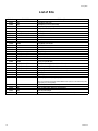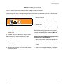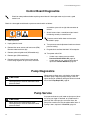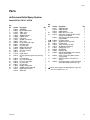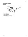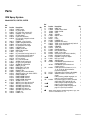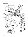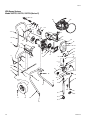
1
Repair
Airless Sprayer
309477F
US Patent 6,752,067
Europe Patent 1 208 287
- For portable spray applications of architectural paints and coatings (Specifications, page 3)
Important Safety Instructions
Read all warnings and instructions in this
manual. Save these instructions.
WLE
WLD
ti2015b
dx Pressure Roller/Spray System
Models 232736, 232737, 232738 - Series B
XR9 Sprayer
Models 232751, 232752, 232753 - Series A,B, C
Related Manuals
dx Pressure Roller
Operation:
XR9 Operation:
SG3 Gun:
3W9470, 3X9470, 3Y9470, 3Z9470
3W9478, 3X9478, 3Y9478, 3Z9478
309097
Graco Inc. P.O. Box 1441 Minneapolis, MN 55440-1441
Copyright 2002, Graco Inc. is registered to I.S. EN ISO 9001
Contents
Manual Conventions . . . . . . . . . . . . . . . . . . . . . . . . . . . . . . . . . . . . . . . . . . . . . . . . . . . . . . . . . . . . . . . . . . . . . . . . . 3
Specifications . . . . . . . . . . . . . . . . . . . . . . . . . . . . . . . . . . . . . . . . . . . . . . . . . . . . . . . . . . . . . . . . . . . . . . . . . . . . . . 3
Warnings . . . . . . . . . . . . . . . . . . . . . . . . . . . . . . . . . . . . . . . . . . . . . . . . . . . . . . . . . . . . . . . . . . . . . . . . . . . . . . . . . . 4
Pressure Relief Procedure . . . . . . . . . . . . . . . . . . . . . . . . . . . . . . . . . . . . . . . . . . . . . . . . . . . . . . . . . . . . . . . . . . . . 6
Grounding and Electrical Requirements . . . . . . . . . . . . . . . . . . . . . . . . . . . . . . . . . . . . . . . . . . . . . . . . . . . . . . . . . . 7
Thermal Overload . . . . . . . . . . . . . . . . . . . . . . . . . . . . . . . . . . . . . . . . . . . . . . . . . . . . . . . . . . . . . . . . . . . . . . . . 7
General Repair Information . . . . . . . . . . . . . . . . . . . . . . . . . . . . . . . . . . . . . . . . . . . . . . . . . . . . . . . . . . . . . . . . . . . . 8
Basic Troubleshooting . . . . . . . . . . . . . . . . . . . . . . . . . . . . . . . . . . . . . . . . . . . . . . . . . . . . . . . . . . . . . . . . . . . . . . . . 9
Advanced Troubleshooting . . . . . . . . . . . . . . . . . . . . . . . . . . . . . . . . . . . . . . . . . . . . . . . . . . . . . . . . . . . . . . . . . . . 11
General Problem: Motor Does Not Operate . . . . . . . . . . . . . . . . . . . . . . . . . . . . . . . . . . . . . . . . . . . . . . . . . . . 11
General Problem: Circuit Breaker is Tripping . . . . . . . . . . . . . . . . . . . . . . . . . . . . . . . . . . . . . . . . . . . . . . . . . . 13
General Problem: Erratic Motor Operation . . . . . . . . . . . . . . . . . . . . . . . . . . . . . . . . . . . . . . . . . . . . . . . . . . . . 14
General Problem: Low or Fluctuating Output . . . . . . . . . . . . . . . . . . . . . . . . . . . . . . . . . . . . . . . . . . . . . . . . . . 15
General Problem: No Output . . . . . . . . . . . . . . . . . . . . . . . . . . . . . . . . . . . . . . . . . . . . . . . . . . . . . . . . . . . . . . . 17
General Problem: Excessive Pressure Build Up . . . . . . . . . . . . . . . . . . . . . . . . . . . . . . . . . . . . . . . . . . . . . . . . 17
List of Kits . . . . . . . . . . . . . . . . . . . . . . . . . . . . . . . . . . . . . . . . . . . . . . . . . . . . . . . . . . . . . . . . . . . . . . . . . . . . . . . . 18
Motor Diagnostics . . . . . . . . . . . . . . . . . . . . . . . . . . . . . . . . . . . . . . . . . . . . . . . . . . . . . . . . . . . . . . . . . . . . . . . . . . 19
Control Board Diagnostics . . . . . . . . . . . . . . . . . . . . . . . . . . . . . . . . . . . . . . . . . . . . . . . . . . . . . . . . . . . . . . . . . . . . 20
Pump Diagnostics . . . . . . . . . . . . . . . . . . . . . . . . . . . . . . . . . . . . . . . . . . . . . . . . . . . . . . . . . . . . . . . . . . . . . . . . . . 20
Pump Service . . . . . . . . . . . . . . . . . . . . . . . . . . . . . . . . . . . . . . . . . . . . . . . . . . . . . . . . . . . . . . . . . . . . . . . . . . . . . 20
Parts . . . . . . . . . . . . . . . . . . . . . . . . . . . . . . . . . . . . . . . . . . . . . . . . . . . . . . . . . . . . . . . . . . . . . . . . . . . . . . . . . . . . 21
dx Pressure Roller/Spray System . . . . . . . . . . . . . . . . . . . . . . . . . . . . . . . . . . . . . . . . . . . . . . . . . . . . . . . . . . . 21
Pressure Roller Assembly . . . . . . . . . . . . . . . . . . . . . . . . . . . . . . . . . . . . . . . . . . . . . . . . . . . . . . . . . . . . . . . . . 23
Parts . . . . . . . . . . . . . . . . . . . . . . . . . . . . . . . . . . . . . . . . . . . . . . . . . . . . . . . . . . . . . . . . . . . . . . . . . . . . . . . . . . . . 24
XR9 Spray System . . . . . . . . . . . . . . . . . . . . . . . . . . . . . . . . . . . . . . . . . . . . . . . . . . . . . . . . . . . . . . . . . . . . . . 24
XR9 Spray System Labels . . . . . . . . . . . . . . . . . . . . . . . . . . . . . . . . . . . . . . . . . . . . . . . . . . . . . . . . . . . . . . . . 27
Technical Data . . . . . . . . . . . . . . . . . . . . . . . . . . . . . . . . . . . . . . . . . . . . . . . . . . . . . . . . . . . . . . . . . . . . . . . . . . . . . 29
Graco Warranty . . . . . . . . . . . . . . . . . . . . . . . . . . . . . . . . . . . . . . . . . . . . . . . . . . . . . . . . . . . . . . . . . . . . . . . . . . . . 30
2
309477F
Manual Conventions
Manual Conventions
WARNING
Hazard Symbol
WARNING: a potentially hazardous situation which, if
not avoided, could result in death or serious injury.
Warnings in the instructions usually include a symbol
indicating the hazard. Read the general Warnings
section for additional safety information.
CAUTION
CAUTION: a potentially hazardous situation which, if
not avoided, may result in property damage or
destruction of equipment.
Note
Additional helpful information.
Specifications
This equipment is not intended for use with flammable or combustible materials used in places such as cabinet shops
or other “factory”, or fixed locations. If you intend to use this equipment in this type of application, you must comply
with NFPA 33 and OSHA requirements for the use of flammable and combustible materials.
309477F
3
Warnings
Warnings
The following are general related to the safe setup, grounding, use, maintenance, and repair of this equipment. Additional, more specific warnings may be found throughout the text of this manual, where applicable.
WARNING
FIRE AND EXPLOSION HAZARD
Flammable fumes, such as solvent and paint fumes, in work area can ignite or explode. To help prevent
fire and explosion:
• Use equipment only in well ventilated area.
• Eliminate all ignition sources; such as pilot lights, cigarettes, portable electric lamps, and plastic drop
cloths (potential static arc).
• When flammable liquid is used in or near the sprayer or for flushing or cleaning, keep sprayer at least
20 feet (6 m) away from explosive vapors.
• Do not clean with materials having flash points lower than 70°F (21°C). Use water-based materials
or mineral spirits type material only. For complete information about your fluid, request the MSDS
from the fluid distributor or retailer.
• Keep work area free of debris, including solvent, rags and gasoline.
• Do not plug or unplug power cords or turn lights on or off when flammable fumes are present.
• Ground equipment and conductive objects in work area. See Grounding instructions.
• If there is static sparking or you feel a shock, stop operation immediately. Do not use equipment
until you identify and correct the problem.
• Keep a working fire extinguisher in the work area.
ELECTRIC SHOCK HAZARD
Improper grounding, setup, or usage of the system can cause electric shock.
• Turn off and disconnect power cord before servicing equipment.
• Use only grounded electrical outlets.
• Use only 3-wire extension cords.
• Ensure ground prongs are intact on sprayer and extension cords.
SKIN INJECTION HAZARD
High-pressure fluid from gun, hose leaks, or ruptured components will pierce skin. This may look like just
a cut, but it is a serious injury that can result in amputation. Get immediate surgical treatment.
• Do not point gun at anyone or at any part of the body.
• Do not put your hand over the spray tip.
• Do not stop or deflect leaks with your hand, body, glove, or rag.
• Engage trigger lock when not spraying.
• Follow Pressure Relief Procedure in this manual, when you stop spraying and before cleaning,
checking, or servicing equipment.
4
309477F
WARNING
WARNING
EQUIPMENT MISUSE HAZARD
Misuse can cause death or serious injury.
• Do not exceed the maximum working pressure or temperature rating of the lowest rated system
component. See Technical Data in all equipment manuals.
• Use fluids and solvents that are compatible with equipment wetted parts. See Technical Data in all
equipment manuals. Read fluid and solvent manufacturer’s warnings.
• Check equipment daily. Repair or replace worn or damaged parts immediately.
• Do not alter or modify equipment.
• Use equipment only for its intended purpose. Call your Graco distributor for information.
• Route hoses and cables away from traffic areas, sharp edges, moving parts, and hot surfaces.
• Do not kink or over bend hose or use hoses to pull equipment.
• Keep children and animals away from work area.
• Comply with all applicable safety regulations.
BURN HAZARD
Equipment surfaces and fluid that’s heated can become very hot during operation. To avoid severe
burns, do not touch hot fluid or equipment. Wait until equipment/fluid has cooled completely.
PRESSURIZED ALUMINUM PARTS HAZARD
Do not use 1,1,1-trichloroethane, methylene chloride, other halogenated hydrocarbon solvents or fluids
containing such solvents in pressurized aluminum equipment. Such use can cause serious chemical
reaction and equipment rupture, and result in death, serious injury, and property damage.
TOXIC FLUID OR FUMES HAZARD
Toxic fluids or fumes can cause serious injury or death if splashed in the eyes or on skin, inhaled, or
swallowed.
• Read MSDS’s to know the specific hazards of the fluids you are using.
• Store hazardous fluid in approved containers, and dispose of it according to applicable guidelines.
PERSONAL PROTECTIVE EQUIPMENT
You must wear appropriate protective equipment when operating, servicing, or when in the operating
area of the equipment to help protect you from serious injury, including eye injury, inhalation of toxic
fumes, burns, and hearing loss. This equipment includes but is not limited to:
• Protective eye wear
• Clothing and respirator as recommended by the fluid and solvent manufacturer
• Gloves
• Hearing protection
309477F
5
Pressure Relief Procedure
Pressure Relief Procedure
To help prevent injuries, follow this procedure
when you stop spraying and before you service or
clean the sprayer, remove parts or repair leaks.
3. Turn Prime/Spray valve to PRIME. Trigger gun to
relieve pressure in hose.
1. Turn OFF power switch.
to2012a
ti2018a
ti2011
dx model
4. Engage trigger safety.
XR9 model
2. Unplug sprayer.
ti2048a
Leave Prime/Spray valve in PRIME position until
you are ready to spray again.
ti2021a1
6
If you suspect the spray tip or hose is completely
clogged or that pressure has not been fully relieved after
following the above steps, VERY SLOWLY loosen the tip
guard retaining nut or hose end coupling to relieve
pressure gradually. Then loosen it completely. Clear tip
or hose obstruction.
309477F
Grounding and Electrical Requirements
Grounding and Electrical Requirements
This sprayer requires 220-240 VAC, 50/60 Hz, 10A
circuit with a grounding receptacle. Do not use an outlet
that is not grounded.
Spray gun: ground through connection to a properly
grounded fluid hose and pump.
Fluid supply container: follow local code.
Solvent pails used when flushing: follow local code.
Use only conductive metal pails, placed on a grounded
surface such as concrete. Do not place the pail on a
nonconductive surface, such as paper or cardboard,
which interrupts grounding continuity.
ti2021a
Do not use the sprayer if the electrical cord has a
damaged ground prong. Only use an extension cord
with an undamaged 3-prong plug.
Grounding the metal pail: connect a ground wire to the
pail by clamping one end to pail and other end to ground
such as a water pipe.
To maintain grounding continuity when flushing or
relieving pressure: hold metal part of the spray gun
firmly to the side of a grounded metal pail, then trigger
the gun.
Thermal Overload
ti2022a
Only use an extension cord with an undamaged 3-prong
plug. Recommended extension cords for use with this
sprayer are:
• 15 m (49.2 ft) 1.0 mm2
• 30 m (88.4 ft) 1.5 mm2
• 50 m (164.0 ft) 2.5 mm2
Motor has a thermal overload switch to shut itself down
if overheated.
WARNING
To reduce risk of injury from motor starting unexpectedly when it cools, always turn power switch
OFF if motor shuts down.
Smaller-gauge or longer extension cords may
reduce sprayer performance.
309477F
7
General Repair Information
General Repair Information
•
WARNING
Page 4.
•
Keep all screws, nuts, washers, gaskets, and
electrical fittings removed during repair procedures.
These parts are not normally provided with
replacement assemblies.
•
Test repair after problem is corrected.
•
If sprayer does not operate properly, review repair
procedure to verify you did it correctly. See Basic
Troubleshooting, page 9 and Advanced
Troubleshooting, page 11.
•
8
Overspray may build up in the air passages.
Remove any overspray and residue from the air
passages and openings in the enclosures whenever
you service the sprayer.
Do not operate the sprayer without the enclosure.
Replace if damaged. Enclosures direct cooling air
around the motor to prevent overheating. They also
reduce the risk of burns, fire or explosion.
CAUTION
Do not run sprayer dry for more than 30 seconds.
Doing so could damage pump packings.
Protect internal drive parts of this sprayer from
water. Openings in enclosures allow for air
cooling of mechanical parts and electronics
inside. If water gets into these openings, the
sprayer could malfunction or be permanently
damaged.
Prevent pump corrosion and damage from
freezing. Never leave water or water-based paint
in sprayer when it is not in use in cold weather.
Freezing fluids can seriously damage sprayer.
Store sprayer with mineral spirits/paint thinner or
Graco Pump Armor to protect equipment during
storage.
309477F
Basic Troubleshooting
Basic Troubleshooting
The following troubleshooting guidelines are included here as preemptive measures against Advanced
Troubleshooting, page 11.
Problem
Cause
Power switch is on and sprayer Pressure is set at zero
pressure
is plugged in, but motor does
not run and pump does not
Motor control is damaged
cycle
Electrical outlet is not providing
power
Pump does not prime
Spray gun stopped spraying
Solution
Turn pressure control knob counterclockwise to
increase pressure setting.
See Motor Does Not Operate, page 11.
•
Try a different outlet or plug in something that
you know is working to test outlet
•
Reset building circuit breaker or replace fuse
Extension cord is damaged
Replace extension cord. See Grounding and
Electrical Requirements, page 7.
Sprayer electrical cord is
damaged
Check for broken insulation or wires. Replace
electrical cord if damaged.
Paint is frozen or hardened in
pump
See Motor Does Not Operate, page 11.
Spray-PRIME valve is in
SPRAY position
Turn Prime/Spray valve to PRIME position
(pointing down).
Inlet screen is clogged or
suction tube is not immersed
Clean debris off inlet screen and make sure
suction tube is at bottom of paint pail.
Balls in check valve are stuck
or check valves are damaged
Clean or replace check valves. See Pump
Service, page 20. Do not store in water.
Suction tube is leaking
Tighten suction tube connection. Inspect for other
cracks or vacuum leaks.
Spray tip is plugged
Unplug spray tip. Manual 309097.
Pump cycles but does not build Pump is not primed
up pressure
Inlet screen is clogged or
suction tube is not immersed
Prime pump.
Clean debris off inlet screen and make sure
suction tube is at bottom of paint pail.
Paint pail is empty
Refill paint pail and reprime sprayer.
Suction tube is leaking
Tighten suction tube connection. Inspect for other
cracks or vacuum leaks.
Pump check valves are dirty or Clean or replace check valves. See Pump
damaged. (Usually only one
Service, page 20.
valve)
Pump cycles but paint only
dribbles or spurts when spray
gun is triggered
Prime/Spray valve is worn or
obstructed with debris
Check Prime/Spray valve for debris trapped on
seat and worn parts. Torque to 21 N·m (185 in-lb).
Pressure is set too low
Slowly turn pressure control knob clockwise to
increase pressure setting. Sprayer should develop
more pressure.
Spray tip is plugged
Unplug spray tip. Manual 309097.
InstaClean fluid filter is clogged Clean or replace InstaClean fluid filter.
(XR9 only)
Spray gun fluid filter is clogged Clean or replace spray gun fluid filter.
309477F
9
Basic Troubleshooting
Problem
Cause
Spray pattern is inconsistent or Pressure is set too low
is leaving stripes
Pressure is set at maximum
but cannot achieve a good
spray pattern
Solution
Turn pressure control knob clockwise to increase
pressure.
Spray tip is worn beyond
capability of sprayer
Replace spray tip.
Spray tip is too big for sprayer
Select smaller spray tip.
Spray tip is worn beyond
capability of sprayer
Replace spray tip.
Extension cord is too long or
not heavy enough gauge
Replace extension cord. Grounding and
Electrical Requirements, page 7.
Spray gun fluid filter is clogged Clean or replace spray gun fluid filter.
InstaClean fluid filter is clogged Clean or replace InstaClean fluid filter.
(XR9 only)
Inlet screen is clogged
Clean debris off inlet screen.
Pump valves are worn
See Low or Fluctuating Output, page 15.
Motor is hot and runs
intermittently.
This is NOT a thermal overload
condition. Motor automatically
shuts off due to excessive heat.
Damage can occur if cause is
not corrected.
Thermal Overload, page 7.
Vent holes in enclosure are
plugged or sprayer is covered
Keep vent holes clear of obstructions and
overspray and keep sprayer open to air.
Extension cord is too long or
not a heavy enough gauge
Replace extension cord. See Grounding and
Electrical Requirements, page 7.
Unregulated electrical
generator being used has
excessive voltage
Use electrical generator with a proper voltage
regulator. Sprayer requires 220-240 VAC, 50/60
Hz, 1500-Watt generator.
Building circuit breaker opens
after sprayer operates for 5 to
10 minutes.
Too many appliances are
plugged in on same circuit.
Free up circuit (unplug things), or use a less busy
circuit.
Sprayer electrical cord is
damaged.
Check broken insulation or wires. Replace
electrical cord if damaged.
Sprayer was operated at high Decrease pressure setting or increase tip size.
pressure with very small tip
which causes frequent motor
starts and excessive heat build
up
Fan pattern varies dramatically Pressure control switch is worn Replace pressure control knob using Pressure
and causing excessive
Control Switch Kit, page 18.
while spraying
pressure variation
OR
Sprayer does not turn on
promptly when resuming
spraying
Cannot trigger spray gun
Spray gun trigger safety lever is Rotate trigger safety lever to SAFETY OFF
in SAFETY ON position
position.
Spray comes out of spray gun
in two thick streams
Reversible spray tip is in
UNCLOG position
Rotate arrow-shaped handle on spray tip so it
points forward in SPRAY position.
Paint is coming out of pressure Pressure control switch is worn Replace pressure control using Pressure Control
control switch
Switch Kit, page 18.
Spray-PRIME valve actuates
automatically relieving
pressure through drain tube
System is over pressurizing
See Excessive Pressure Build Up, page 17.
Paint leaks down outside of
pump
Pump packings are worn
Replace pump packings. See Pump Service,
page 20.
10
309477F
Advanced Troubleshooting
Advanced Troubleshooting
WARNING
Page 4.
General Problem: Motor Does Not Operate
Specific Problem
Cause
Solution
Power switch is on and sprayer See Basic Troubleshooting,
is plugged in; pump does not
page 9
cycle
Basic mechanical problems
Paint is frozen or hardened in
pump
Unplug sprayer from electrical outlet.
If paint is frozen in sprayer:
•
Do NOT try to start sprayer until completely
thawed or you may damage the motor, control
board, and/or drivetrain.
1. Turn OFF power switch
2. Place sprayer in warm area for several
hours
3. Plug in and turn on sprayer
4. Slowly increase pressure until motor starts
If paint hardened in sprayer:
1. Replace pump packings
2. Remove all residue from valves
Pump Service, page 20.
309477F
Motor is damaged
Remove gear and try to rotate motor shaft by
hand. See Motor Diagnostics, page 19. If shaft
will not turn, replace motor using Motor Kit, page
18.
Yoke is broken because pump
is locked up due to dried paint
or worn packings (XR9 only)
Repair or replace using Gear/Yoke Kit, page 18.
Repair pump, page 20.
11
Advanced Troubleshooting
Specific Problem
Basic electrical problems
Sprayer Wiring Problems
NOTE: Remove enclosure
mounting screws and pull
enclosure away from drive
housing. Take care not to pull
on leads from electrical cord
and power switch.
12
Cause
Solution
Motor overheated
Allow motor to cool for 30 minutes. Retry.
Electrical outlet is damaged
Reset building circuit breaker or replace building
fuse. Try another outlet.
Check electric supply with volt meter. Meter must
read 200-260V AC. If voltage is too high, do not
plug sprayer in until outlet is corrected.
Control board leads are
improperly fastened or
improperly mated
Replace any loose terminals. Make sure all leads
and harnesses are firmly connected.
Check pressure control harness connection on
front side of drive housing.
Clean control board terminals. Securely reconnect
leads.
Motor brushes are worn.
Check length of BOTH brushes (brushes do not
wear evenly on both sides of the motor). Brush
length must be 6.4mm (0.25 in). If brushes are
worn replace motor using Motor Kit, page 18.
Motor armature commutator
damaged
Check for burn spots, gouges and extreme
roughness. Have motor shop resurface
commutator if possible, or replace motor using
Motor Kit, page 18.
Motor armature shorting
Check for shorts using armature tester (growler)
or perform spin test, Motor Diagnostic, page 19.
If shorts are evident, replace motor using Motor
Kit, page 18.
Control board damaged.
CAUTION: Do not perform
control board diagnostics until
you have determined the
armature is good. A bad
armature can burn out a good
control board.
See Control Board Diagnostics, page 19.
Replace control board if damaged using Control
Board Kit, page 18.
Sprayer electrical cord
damaged
1. Unplug sprayer electrical cord.
2. Disconnect black electrical cord wire at
power switch
3. Unplug in-line connection white cord wire.
4. Plug in electrical cord
5. Test voltage between black and white
wires. Meter must read 200-260 V AC.
6. Replace electrical cord if no voltage.
Sprayer power switch damaged
1. Unplug sprayer electrical cord.
2. Disconnect black control board wire at
power switch.
3. Unplug in-line connection white cord wire.
4. Plug in electrical cord.
5. Turn power switch ON.
6. Test voltage between open terminal of
power switch and white electrical cord wire.
Meter must read 200-260 V AC.
7. Replace power switch if no voltage.
309477F
Advanced Troubleshooting
Specific Problem
Cause
Sprayer Wiring Problems
(cont.)
Motor thermal overload cutoff
switch damaged.
Thermal Overload, page 7.
Terminals are damaged or
loose
Solution
1. Unplug sprayer electrical cord.
2. Remove motor harness from control card
3. Check for continuity between yellow leads
or motor harness.
4. If thermal relief switch is open (no continuity) allow motor to cool.
5. If switch remains open after motor cools,
replace motor using Motor Kit, page 18.
6. If thermal relief switch closes after motor
cools, find correct cause of overheating.
Replace any damaged terminals. Make sure all
terminal connections are tight.
General Problem: Circuit Breaker is Tripping
Specific Problem
Cause
Building circuit breaker opens Sprayer electrical wiring is
as soon as sprayer is turned on pinched or insulation is
damaged.
Solution
Repair or replace any damaged wiring or
terminals. Securely reconnect wires.
Wires between pressure
control switch and control
board are pinched
Motor armature is shorting
Check for shorts using armature tester (growler)
or perform spin test, Motor Diagnostics, page
19. If shorts are evident, replace motor using
Motor Kit, page 18.
See Control Board Diagnostics, page 19.
Control board is damaged.
Replace control board if damaged using Control
CAUTION: Do not perform
control board diagnostics until Board Kit, page 18.
you have determined the
armature is good. A bad motor
armature can burn out a good
motor control board.
309477F
13
Advanced Troubleshooting
Specific Problem
Cause
Building circuit breaker opens
as soon as sprayer is plugged
into outlet and sprayer is NOT
turned on.
NOTE: Remove enclosure
mounting screws and pull
enclosure away from drive
housing. Take care not to pull
on leads from electrical cord
and power switch.
Solution
Sprayer electrical cord is
damaged
1. Unplug sprayer electrical cord.
2. Disconnect black electrical cord wire at
power switch
3. Unplug in-line connection white cord wire.
4. Plug in electrical cord
5. Test voltage between black and white
wires. Meter must read 200-260 V AC.
6. Replace electrical cord if no voltage.
Sprayer power switch damaged
1. Unplug sprayer electrical cord.
2. Disconnect black control board wire at
power switch.
3. Check resistance of switch with ohmmeter.
4. Reading must be infinity with power switch
OFF.
5. Reading must be zero with power switch
ON.
6. Replace power switch if damaged.
Also “Basic Electrical Problems” and “Sprayer Wiring Problems”, page 12.
General Problem: Erratic Motor Operation
Specific Problem
Sprayer quits after running for
5 to 10 minutes
Cause
Solution
Electrical outlet is damaged
Reset building circuit breaker or replace building
fuse.
Electrical outlet supplying
wrong voltage
Try another outlet. Check electric supply with volt
meter. Meter must read 200-260 V AC. If voltage
is too high, do not use outlet until corrected.
Also “Basic Electrical Problems” and “Sprayer Wiring Problems”, page 12.
Motor is overheating
14
“Motor is Hot”, page 10.
309477F
Advanced Troubleshooting
General Problem: Low or Fluctuating Output
Specific Problem
Pump cycles, but output is low
or surging
Cause
Solution
See Basic Troubleshooting,
page 9.
Worn or obstructed pump
valves
Check for worn pump valves as follows:
Prime/Spray valve is leaking
Check Prime/Spray valve for debris trapped on
seat and for worn parts. Torque to 21 N•m (185
in-lb). Replace if parts are worn using
Prime/Spray Drain Valve Kit, page 18.
1. Prime sprayer with paint.
2. Trigger spray gun momentarily.
3. When spray gun trigger is released pump
should cycle momentarily and stop.
4. If pump continues to cycle, pump valves
may be worn or obstructed.
5. Pump Service, page 20.
Voltage from electrical outlet is Check voltage of outlet. Meter must read 200-260
too low. Low voltages reduce
V AC.
Reset building circuit breaker or replace building
sprayer performance.
fuse.
Repair electrical outlet or try another outlet.
Extension cord is too long or
not heavy enough gauge
Replace extension cord.
Grounding and Electrical Requirements, page
7.
Leads from motor or pressure
switch to control board are
damaged, loose, pinched, or
overheated
Be sure terminals are centered and firmly
connected. Inspect for pinched wiring and wiring
insulation and terminals for signs of overheating.
Replace any loose terminals or damaged wiring.
Securely reconnect terminals.
Motor brushes are worn
Check length of BOTH brushes (brushes to not
wear evenly on both sides of the motor). Brush
length must be 6.4mm (0.25 in). If brushes are
worn replace motor using Motor Kit, page 18.
Motor brush springs are broken If springs are broken replace motor using Motor
Kit, page 18.
Motor brushes are binding in
brush holders
Clean brush holders. Remove carbon dust with
small cleaning brush.
Motor stops before sprayer
Replace pressure control using Pressure Control
reaches correct pressure (stall Switch Kit, page 18.
pressure is too low)
Motor armature shorted
309477F
Check for shorts using armature tester (growler)
or perform spin test, Motor Diagnostics, page
19. If shorts are evident, replace motor using
Motor Kit, page 18.
15
Advanced Troubleshooting
Specific Problem
Cause
Solution
See Control Board Diagnostics, page 19. If
Control board is damaged.
damaged replace control board using Control
CAUTION: Do not perform
control board diagnostics until Board Kit, page 18.
you have determined the
armature is good. A bad motor
can burn out a good control
board.
Motor runs and pump cycles,
but pressure does not build up
Intake valve ball or outlet valve Remove and clean valves and check balls and
ball is not seating properly
seats for nicks; replace if necessary. Strain paint
before spraying to remove particles that could clog
pump. Pump Service, page 20.
Pump packings are worn or
damaged
Check for leaking around throat packing nut.
Replace pump packings if there are leaks. Pump
Service, page 20.
Prime/Spray Valve leaking
Check Prime/Spray Valve for debris trapped on
seat and for worn parts. Torque to 21 N•m (185
in-lb). If parts are worn, replace valve using
Prime/Spray Drain Valve Kit, page 18.
Leads from motor or pressure
Spray pattern has variations,
switch to control board are
pressure fluctuates
excessively, or motor runs very damaged, loose or overheated
slowly
16
Be sure terminals are centered and firmly
connected. Inspect wiring insulation and terminals
for signs of overheating. Replace any loose
terminals or damaged wiring. Securely reconnect
terminals.
Pressure control switch leads
are pinched between pump
and drive housing or between
front cover and drive housing
(XR9 only)
Make sure pressure control harness is routed
behind pump, through retention clip and
connected to control board connector on control
board (connect with tab to right).
Control board is damaged.
CAUTION: Do not perform
control board diagnostics until
you have determined the
armature is good. A bad
armature can burn out a good
control board.
See Control Board Diagnostics, page 19. If
damaged, replace control board using Control
Board Kit, page 18.
Pressure control switch is
damaged or worn out
Replace pressure control switch using Pressure
Control Switch Kit, page 18.
309477F
Advanced Troubleshooting
General Problem: No Output
Specific Problem
Cause
Solution
Power switch is on and sprayer See Basic Troubleshooting,
is plugged in but pump does
page 9.
not cycle
Motor runs but pump does not
cycle
Gear and/or yoke are damaged Replace gear and yoke using Gear/Yoke Repair
(XR9 only)
Kit, page 18.
Motor does not run
Water or paint entered
pressure control switch or
shorted control board
Clean out and/or dry out and retry. Replace if
necessary using Pressure Control Switch Kit,
page 18.
General Problem: Excessive Pressure Build Up
Specific Problem
Prime/Spray Valve actuates
automatically, relieving
pressure through drain tube.
309477F
Cause
Solution
Pressure control switch is worn Replace pressure control switch using Pressure
Control Switch Kit, page 18.
Water or paint entered
pressure control switch or
shorted control board
Clean out and/or dry out and retry. Replace if
necessary using Pressure Control Switch Kit,
page 18.
Control board failed
See Control Board Diagnostics, page 19.
Replace damaged control board using Control
Board Kit, page 18.
17
List of Kits
List of Kits
Kit Number
235014
243082
243090
245077
245070
15A473
15D883
15A475
245076
243094
244035
246286
245677
245665
243231
287770
245062
245064
245667
287784
245595
287785
245078
245646
245053
Models/Series
All
All
XR9
dx
XR9
dx, XR9 Series A
XR9 Series B, C
All
dx
XR9
All
All
dx
XR9
XR9 Series A, B
XR9 Series C
XR9
XR9
XR9 Series A, B
XR9 Series C
XR9 Series A, B
XR9 Series C
dx
dx
XR9
Kit Description
Prime/Spray Drain Valve
Inlet Strainer (or inlet of suction tube)
Pump Repair (pump packing module)
Pump Inlet Valve Module
Pump Inlet Valve Module
Suction Tube
Suction Tube
Drain Tube
Pump Outlet Valve Module
Pump Outlet Valve Module
Drain Tube Diffuser
Pressure Control Switch
Control Board
Control Board
Fan/Shroud/Brace
Fan
Shaft Gear/Yoke/Guides
Front Cover (with ID label)
Motor/Drive Housing (includes fan/shroud/brace)
Motor/Drive Housing (includes fan)
Enclosure (includes both sides, labels and screws)
Enclosure (includes both sides, labels and screws)
Pump Repair
Motor Repair
XR Pump Replacement (complete pump*)
* Does not include Pressure Control Switch 244267. Reuse pressure control switch from pump
being replaced or order separately.
245647
245678
245821
248202
18
dx
dx
All
XR9
Enclosure (includes labels and screws)
Cover (includes labels, bushings, and dowel pins)
Gear Lubrication/Repair
Lacquer Conversion (lacquer compatible suction tube and seals)
309477F
Motor Diagnostics
Motor Diagnostics
Check for electrical continuity in motor armature, windings and brush as follows:
If Motor Diagnostics reveal a damaged motor or if motor brushes are shorter than 6.4 mm (1/4 in.) or if the motor
shaft cannot turn, replace the motor using Motor Kit, page 18.
4. Remove fan brace.
WARNING
0
MPa/bar/PSI
Page 4.
5. Remove four screws and front cover.
6. Remove yoke and guide rods (XR9 model only).
7. Remove gear.
Both Models
Armature Short Circuit Spin Test (XR9 model only)
1. Relieve pressure.
Quickly turn motor fan by hand. There should not be
electrical shorts and fan should coast two or three
revolutions before stopping. If fan does not spin freely,
armature is shorted. Replace motor using Motor Kit,
page 18.
2. Remove enclosure and disconnect motor leads from
control card.
3. Connect standard 9V DC battery using test leads.
Motor and drive train should slowly rotate if motor
functioning and drive train is free.
Armature, Brushes and Motor Wiring Open Circuit
Test (Continuity) (XR9 model only)
Setup (XR9 model only)
1. Connect red and black motor leads together with
test lead.
1. Relieve pressure.
2. Unplug electrical cord.
2. Turn motor fan by hand, about two revolutions per
second.
3. Remove right enclosure. Disconnect motor harness
from control board.
3. If there is an uneven resistance or no resistance,
replace motor using Motor Kit, page 18.
309477F
19
Control Board Diagnostics
Control Board Diagnostics
Check for motor problems before replacing control board. A damaged motor may burn out a good
control card
Check for a damaged control board or pressure control switch as follows:
screwdriver, press tab on right side connector to
release.
WARNING
7. Attach harness from a control board you know is
functioning correctly to control board.
Page 4, 6.
Pressure control switch does not have to be
installed in pump.
1. Relieve pressure.
2. Unplug electrical cord.
3. Remove four cover screws and front cover (XR9).
Remove motor enclosure (dx).
4. Remove yoke and guide rods (XR9 model only).
8. Turn pressure control adjustment knob to maximum
pressure setting.
9. Plug electrical cord into 220-240 V AC receptacle.
10. Turn power switch ON.
5. Remove gear (XR9 model only).
•
6. Remove pressure control harness from control
board. Using fingernail or tip of small, flat blade
•
If motor runs, replace pressure switch.
Pressure Control Switch Kit, page 18.
If motor does not run, replace control board
repeat test. Control Board Kit, page 18.
Pump Diagnostics
CAUTION
When repairing or cleaning the pump, never
submerge pump in water or allow fluid to enter
pressure control.
When pump packings wear, paint begins to leak down
outside of pump. Replace pump packings at the first
sign of leaking or additional damage to drive train could
occur. Use Pump Repair Kit, page 18.
Pump Service
CAUTION
When repairing or cleaning pump, never
submerge pump in water or allow fluid to enter
pressure control.
20
If sprayer continues to cycle (motor and pump run) when
the spray gun trigger is released, or if performance is
poor even with new spray tips and clean filters, the
pump inlet or outlet valve may be obstructed or worn. If
a pump is worn, replace it. List of Kits, page 18.
309477F
Parts
Parts
dx Pressure Roller/Spray System
Model 232736, 232737, 232738
Ref
No.
2
3
5
12
13
15
16
18
19
23
30
31
32
38
41
42
43
44
50
51
52
53
54
55
56
57
Part No.
243082
244035
15A473
15A475
115489
15A680
15H772
113955
102040
246286
224807
235014
111600
187625
245647
245678
117220
245149
245078
245677
245646
245076
245077
116295
115478
245725
245726
309477F
Description
Qty
STRAINER
1
DEFLECTOR, barbed
1
TUBE, suction
1
TUBE, spray
1
CLAMP, drain tube
2
FRAME, stand
1
LEG, stand
2
SCREW, curved head
4
NUT, locking
4
KIT, pressure switch repair
1
CAM, drain valve
1
KIT, valve repair
1
DRIVE PIN, drain valve
1
HANDLE, drain valve
1
KIT, motor enclosure
1
KIT, cover
1
PLUG, snap in
1
KIT, gear (includes 2 gears and connecting
1
rod)
KIT, pump repair
1
KIT, control board 230V
1
KIT, motor repair 230V
1
KIT, outlet valve
1
KIT, inlet valve
1
CLAMP, spring,.88 dia.
1
SCREW, machine, pan head
2
CORD, Schuko CEE7/7
1
CORD, Italy
1
Ref
No.
Part No.
245727
245728
245729
241922
243238
61V
63
64
69
70
71
72
73
75
243308
115477
196574
115648
117219
115632
245648
15A467
245589
Description
CORD, Denmark
CORD, Australia
CORD, Sweden
HOSE, paint, 1/4 in. x 25 ft
GUN, spray, (models 232736 & 232737)
includes manual 309097
GUN, spray (model 232738) includes
manual 309097
KIT, label, warning
SCREW, machine, pan head
FITTING, drain
VALVE, shutoff, power flush
SCREW, M3, washerhead
CLAMP, power cord
FILTER, EMI
BRACKET, filter
ROLLER ACCESSORY (manual 3W9470,
76
245590
VALVE, roller (manual 3W9470, 3X9470,
58
59
243382
Qty
1
1
1
1
1
1
1
9
1
1
2
1
1
1
1
3X9470, 3Y9470, 3Z9470)
1
3Y9470, 3Z9470)
77
246187
78
245856
ADAPTER, Geka to 3/4 in. GHT (not
shown)
KIT, pressure gage (not shown) (included
with models 232736 and 232737 only).
1
1
V Replacement Danger and Warning labels, tags, and
cards are available at no cost.
21
Parts
dx Pressure Roller/Spray System
Model 232736, 232737, 232738
1
42
Apply light coat of lithium-based grease
43
44
30, 32, 38
53
1 50
31
64
13
63
54
23
57
52
51
12
55
63
70
61
71
72
5
7
73
58
41
13
19
63
59
61
3
56
18
15
2
69
76
16
75
WLE
ti2083a
22
309477F
Parts
Pressure Roller Assembly
Model 245589
b
e
a
d
f
c
75a
75b
75c
75d
75e
75f
15A586
245999
246277
15B065
186678
197106
309477F
TUBE, extension
CAP, end, roller
CAP, end, roller
CORE, roller
BRUSH, roller, 9 in. x 1/2 in. nap
CLIP, roller
1
1
1
1
1
1
23
Parts
Parts
XR9 Spray System
Model 232751, 232752, 232753
Ref
No.
1
2
13
17
18
19
20
25
26
36
40
43
44
45
46
47
48
51
52
54
57
58
59
60
61
62
63
65
66
67
68
69
70
24
Part No.
195126
243090
243094
103338
195947
243070
245070
103413
116295
246286
235014
224807
187625
111600
114687
245667
287784
243231
287770
245665
115477
245062
117219
194507
245823
115632
15A467
245064
245725
245726
245727
245728
245729
115478
117223
119904
195433
15D923
195434
15D924
195439
195438
Description
PUMP, housing
KIT, pump repair
KIT, outlet valve (includes #17)
PACKING, o-ring, outlet valve
FILTER, adapter
PUMP, filter, InstaClean
KIT, inlet valve, intergral hose barb
(includes #25)
PACKING, o-ring, inlet valve
CLAMP, spring, 0.88 diameter
KIT, pressure switch, repair
KIT, spray/prime valve repair
CAM, drain valve
HANDLE, drain valve
DRIVE PIN, drain valve
CLIP, retainer
KIT, motor/drive housing, Series A, B
KIT, motor/drive housing, Series C
KIT, fan and shield, Series A, B
KIT, fan, Series C
KIT, control board 230V
SCREW, thread forming, #8
KIT, gear, yoke, guide repair
SCREW, M3, washerhead
DOWEL, pin 5/16
RECEPTACLE, IEC 320
RETAINER, power cord
BRACKET, filter
COVER, front (includes ID labels)
ADAPTER, power cord, Schuko CEE7/7
POWER CORD, Italy
POWER CORD, Denmark
POWER CORD, Australia
POWER CORD, Switzerland
SCREW, torx/slt, 1/4 in.
SWITCH, rocker, dpst, Series A, B
SWITCH, rocker, dspt, Series C
SUPPORT, right, Series A
SUPPORT, right, Series B, C
SUPPORT, left, Series A
SUPPORT, right, Series B, C
FRAME, cart
HANDLE, cart
Qty
1
1
1
1
1
1
1
1
1
1
1
1
1
1
1
1
1
1
1
1
11
1
2
2
1
1
1
1
1
1
1
1
1
8
1
1
1
1
1
1
1
1
Ref
No.
71
72
73
74
75
76
77
78
80
83
84
85
86
87
94
95
96
101
112
123
124
Part No.
15D650
116630
115480
195366
195367
115094
112612
105521
195105
115099
15A473
15D883
243082
15A475
115489
244035
243024
243238
243382
115719
115651
196001
245666
287785
127
245053
147
148
197211
246187
149V
150
151V
152V
V
245856
Description
Qty
HOSE, rack
2
SCREW, square shank
6
KNOB, t-handle
2
AXLE
1
SPACER
2
WHEEL, 10 in.
2
CAP
2
PLUG
2
HANGER, pail
1
WASHER, inlet strainer
1
TUBE, suction, barb (includes 83), Series A 1
TUBE, suction, Series B, C
1
STRAINER
1
TUBE, drain
1
CLAMP, drain tube
2
DEFLECTOR, barbed
1
HOSE, 1/4 in. x 50 ft
1
GUN, spray (model 232751 & 232752)
1
GUN, spray (model 232753)
1
PACKING, o-ring, filter, adapter
1
NUT, hex, 5/16 in.
4
SPACER, pump
2
ENCLOSURE (includes labels and
1
screws), Series A, B
ENCLOSURE (includes labels and
1
screws), Series C
1
PUMP, replacement (includes, #1, 2, 13,
17, 18, 19, 20, 40. Item #36 must be
purchased separately)
CAP, pump outlet (included in Kit 245064)
1
1
ADAPTER, Geka to 3/4 in. GHT (not
shown)
LABEL, warning, multiple languages, see
1
page 27 for specific part numbers
KIT, pressure gage (not shown) (included
1
with models 232751 and 232752 only)
LABEL, danger, multiple languages, see
1
page 27 for specific part numbers
LABEL, danger, multiple languages, see
1
page 27 for specific part numbers
Replacement Danger and Warning labels, tags, and
cards are available at no cost.
309477F
Parts
XR9 Spray System
Model 232751, 232752, 232753 9 (Series A, B)
63
60
1 Apply light coat of lithium-based grease
59
71
61
51
52
57
47
66
112
124
151
52
70
48
62
65
73
147
71
72
124
149
46
152
54
58
80
123
52
127
72
112
13
2
69
75
17
1
65
1
74
40
67
79
36
43, 44, 45
87
18
19 101
25
20
68
86
26
77
84
78
76
87
95
94
83
85
96
ti2084
309477F
25
Parts
XR9 Spray System
Model 232751, 232752, 232753 (Series C)
WLD
26
309477F
Parts
XR9 Spray System Labels
Ref
No.
149
Qty
Part No.
195792
195793
195794
195795
151
15A673
15G238
15A675
15G240
15A677
15G242
15A708
15G237
195834
309477F
Description
LABEL, warning, English Japanese,
Chinese, Korean
LABEL, warning, French, Spanish, German
LABEL, warning, Portuguese, Dutch,
Italian, Greek
LABEL, warning, Swedish, Danish, Finnish,
Norwegian
LABEL, danger, Italian, Danish, German,
Series A, B
LABEL, danger, Italian, Danish, German,
Series C
LABEL, danger, Finnish, Norwegian,
Swedish, Series A, B
LABEL, danger, Finnish, Norwegian,
Swedish, Series C
LABEL, danger, Portuguese, Spanish,
Greek, Series A, B
LABEL, danger, Portuguese, Spanish,
Greek, Series C
LABEL, danger, Chinese, Korean, English,
Series A, B
LABEL, danger, Chinese, Korean, English,
Series C
LABEL, danger, English Spanish, French,
Series A, B
Ref
No.
1
1
1
152
V
15A674
15G239
1
15A676
1
15G241
1
15A678
1
15G243
1
15A706
1
15G236
1
195835
1
15G187
1
1
Qty
Part No.
15G188
V
Description
LABEL, danger, English Spanish, French,
Series C
LABEL, danger, Italian, Danish, German,
Series A, B
LABEL, danger, Italian, Danish, German,
Series C
LABEL, danger, Finnish, Norwegian,
Swedish, Series A, B
LABEL, danger, Finnish, Norwegian,
Swedish, Series C
LABEL, danger, Portuguese, Spanish,
Greek, Series A, B
LABEL, danger, Portuguese, Spanish,
Greek, Series C
LABEL, danger, Chinese, Korean, English,
Series A, B
LABEL, danger, Chinese, Korean, English,
Series C
LABEL, danger, English, Spanish, French,
Series A, B
LABEL, danger, English, Spanish, French,
Series C
1
1
1
1
1
1
1
1
1
1
1
Replacement Danger and Warning labels, tags, and
cards are available at no cost.
27
Technical Data
Technical Data
Working pressure range
Electric motor
Operating horsepower
Maximum delivery (with tip)
Paint hose
Maximum tip hole size
Weight, sprayer only
Weight, sprayer, hose & gun
Dimensions:
Length
Width
Height
dx Roller/Spray System
0 - 207 bar, 21 MPa (0 - 3,000 psi)
3.5 AMP (open frame, universal)
3/8
0.91 lpm (0.24 gpm)
7.6 m (25 ft) x 1/4 in.
0.38 mm (0.015 in.)
6 kg (13 lb)
7.8 kg (17 lb)
XR9 Sprayer
0 - 207 bar, 21 MPa (0 - 3,000 psi)
4.5 AMP (permanent magnet DC)
7/8
1.44 lpm (0.38 gpm)
15.2 m (50 ft) x 1/4 in.
0.48 mm (0.019 in.)
41 cm (16 in.)
46 cm (18 in.)
53 cm (21 in.)
49.5 cm (19.5 in.)
48.3 cm (19 in.)
101.6 cm (40 in.)*
*Height with folded handle is 66 cm (26 in.)
Power cord
Fluid inlet fitting
Fluid outlet fitting
Inlet screen on suction tube
Wetted parts, pump & hose
Wetted parts, gun
Generator requirement
Electrical power requirement
Storage temperature range *❖
Operating temperature range ✔
3 wire, 1.0
mm2 x
2.0 m (78 in.)
1/4 npsm external thread
450 micron (35 mesh)
stainless steel, brass, ultra-high
molecular weight polyethylene
(UHMWPE), carbide, nylon,
aluminum, PVC, polypropylene,
fluroelastomer
aluminum, brass, carbide, nylon,
plated steel, stainless steel,
UHMWPE, zinc
1500 Watt minimum
220-240 V AC, 50/60 Hz, 1 phase,
10 A
-35° to 71°C (-30° to 160°F)
4° to 46°C (40° to 115°F)
3 wire, 1.0 mm2 x2.0 m (78 in.)
1/4 npsm external thread
450 micron (35 mesh)
stainless steel, brass, leather,
ultra-high molecular weight
polyethylene (UHMWPE), carbide,
nylon, aluminum, PVC,
polypropylene, fluroelastomer
aluminum, brass, carbide, nylon,
plated steel, stainless steel,
UHMWPE, zinc
1500 Watt minimum
220-240 V AC, 50/60 Hz, 1 phase,
10 A
-35° to 71°C (-30° to 160°F)
4° to 46°C (40° to 115°F)
* When pump is stored with non-freezing fluid. Pump damage will occur if water or latex paint freezes in pump.
❖ Damage to plastic parts may result if impact occurs in low temperature conditions.
✔ Changes in paint viscosity at very low or very high temperatures can affect sprayer performance.
28
309477F
Graco Warranty
Graco Warranty
Graco warrants all equipment referenced in this document which is manufactured by Graco and bearing its name to be free from defects in
material and workmanship on the date of sale to the original purchaser for use. With the exception of any special, extended, or limited warranty
published by Graco, Graco will, for a period of twelve months from the date of sale, repair or replace any part of the equipment determined by
Graco to be defective. This warranty applies only when the equipment is installed, operated and maintained in accordance with Graco’s written
recommendations.
This warranty does not cover, and Graco shall not be liable for general wear and tear, or any malfunction, damage or wear caused by faulty
installation, misapplication, abrasion, corrosion, inadequate or improper maintenance, negligence, accident, tampering, or substitution of
non-Graco component parts. Nor shall Graco be liable for malfunction, damage or wear caused by the incompatibility of Graco equipment with
structures, accessories, equipment or materials not supplied by Graco, or the improper design, manufacture, installation, operation or
maintenance of structures, accessories, equipment or materials not supplied by Graco.
This warranty is conditioned upon the prepaid return of the equipment claimed to be defective to an authorized Graco distributor for verification of
the claimed defect. If the claimed defect is verified, Graco will repair or replace free of charge any defective parts. The equipment will be returned
to the original purchaser transportation prepaid. If inspection of the equipment does not disclose any defect in material or workmanship, repairs will
be made at a reasonable charge, which charges may include the costs of parts, labor, and transportation.
THIS WARRANTY IS EXCLUSIVE, AND IS IN LIEU OF ANY OTHER WARRANTIES, EXPRESS OR IMPLIED, INCLUDING BUT NOT LIMITED
TO WARRANTY OF MERCHANTABILITY OR WARRANTY OF FITNESS FOR A PARTICULAR PURPOSE.
Graco’s sole obligation and buyer’s sole remedy for any breach of warranty shall be as set forth above. The buyer agrees that no other remedy
(including, but not limited to, incidental or consequential damages for lost profits, lost sales, injury to person or property, or any other incidental or
consequential loss) shall be available. Any action for breach of warranty must be brought within two (2) years of the date of sale.
GRACO MAKES NO WARRANTY, AND DISCLAIMS ALL IMPLIED WARRANTIES OF MERCHANTABILITY AND FITNESS FOR A
PARTICULAR PURPOSE, IN CONNECTION WITH ACCESSORIES, EQUIPMENT, MATERIALS OR COMPONENTS SOLD BUT NOT
MANUFACTURED BY GRACO. These items sold, but not manufactured by Graco (such as electric motors, switches, hose, etc.), are subject to
the warranty, if any, of their manufacturer. Graco will provide purchaser with reasonable assistance in making any claim for breach of these
warranties.
In no event will Graco be liable for indirect, incidental, special or consequential damages resulting from Graco supplying equipment hereunder, or
the furnishing, performance, or use of any products or other goods sold hereto, whether due to a breach of contract, breach of warranty, the
negligence of Graco, or otherwise.
FOR GRACO CANADA CUSTOMERS
The Parties acknowledge that they have required that the present document, as well as all documents, notices and legal proceedings entered into,
given or instituted pursuant hereto or relating directly or indirectly hereto, be drawn up in English. Les parties reconnaissent avoir convenu que la
rédaction du présente document sera en Anglais, ainsi que tous documents, avis et procédures judiciaires exécutés, donnés ou intentés, à la suite
de ou en rapport, directement ou indirectement, avec les procédures concernées.
ADDITIONAL WARRANTY COVERAGE
Graco does provide extended warranty and wear warranty for products described in the “Graco Contractor Equipment Warranty Program”.
TO PLACE AN ORDER or to identify the nearest
Graco/Magnum distributor, contact us at
1-888-541-9788.
309477F
29
All written and visual data contained in this document reflects the latest product information available at the time of publication.
Graco reserves the right to make changes at any time without notice.
MM 309477F
Graco Headquarters: Minneapolis
International Offices: Belgium, China, Japan, Korea
GRACO INC. P.O. BOX 1441 MINNEAPOLIS, MN 55440-1441
www.graco.com
Rev 9/2006 309477F