1
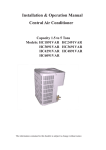
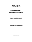
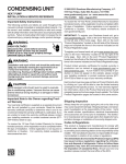
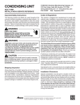
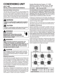
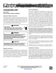
Installation & Operation Manual
Central Air Conditioner
13 SEER 1.5 to 3.5 Ton
Models: HC18D2VAR HC24D2VAR
HC30D2VAR HC36D2VAR
HC42D2VAR
No.0010578572
The information contained in this booklet is subject to change without notice.
! WARNING
These instructions are intended as an aid to qualified, licensed service personnel for proper installation,
adjustment and operation of this unit. Read these instructions thoroughly before attempting installation
or operation. Failure to follow these instructions may result in improper installation, adjustment,
service or maintenance possibly resulting in fire, electrical shock, property damage, personal injury
or death.
This product is designed and manufactured to permit installation in accordance with National Codes. It
is the installer's responsibility to install the product in accordance with National Codes and/or
prevailing local codes and regulations. The manufacturer assumes no responsibility for equipment installed
in violation of any codes or regulations.
The United States Environmental Protection Agency (EPA) has issued various regulations regarding
the introduction and disposal of refrigerants in this unit. Failure to follow these regulations may harm
the environment and can lead to the imposition of substantial fines. Because these regulations may vary
due to the passage of new laws we suggest that any work on this unit be done by a certified technician.
Should you have any questions please contact the local EPA office.
The manufacturer's warranty does not cover any damage or defect to the air conditioner caused by the
attachment or use of any components, accessories or devices (other than those authorized by the manufacturer)
into, onto, or in conjunction with the air conditioner. You should be aware that the use of unauthorized
components, accessories or devices may adversely affect the operation of the air conditioner and
may also endanger life and property. The manufacturer disclaims any responsibility for such loss or
injury resulting from the use of such unauthorized components, accessories or devices.
Attach the service panel to the outdoor unit securely. If the service panel is not attached securely, it
could result in a fire or an electric shock due to dust, water, etc.
Message to Owner
These instructions should be carefully read and kept near the product for future reference. While the instructions are
addressed primarily to the installer, useful maintenance information is included. Have your installer acquaint you with
the operating characteristics of the product and periodic maintenance requirements.
TABLE OF CONTENT
1.Introduction --------------------------------------------------------------------------------------- 1
2.Nomenclature for Model Number ------------------------------------------------------------- 1
3.Specification ------------------------------------------------------------------------------------- 2-3
4.Unit Inspection ----------------------------------------------------------------------------------- 4
5.Equipment Protection From Environment ---------------------------------------------------- 4
6.Installation ---------------------------------------------------------------------------------------- 4
6.1. General --------------------------------------------------------------------------------------- 4
6.2.Unit clearances ------------------------------------------------------------------------------ 5
6.3.Refrigerant piping --------------------------------------------------------------------------- 5
6.4.Electrical wiring ----------------------------------------------------------------------------- 10
7.System Startup ----------------------------------------------------------------------------------- 11
8.Operation ---------------------------------------------------------------------------------------- 12
9.Miscellaneous ----------------------------------------------------------------------------------- 12
9.1.Replacement parts -------------------------------------------------------------------------- 12
9.2.Troubleshooting guide --------------------------------------------------------------------- 12
9.3.Wiring diagram ----------------------------------------------------------------------------- 12
1.INTRODUCTION
This manual contains the installation and operating instructions for your new air conditioner.
Improper installation can result in unsatisfactory operation or dangerous conditions. Carefully
read this manual and any instructions packaged with separate equipment required to make up
the system prior to installation. Give this manual to the owner and explain its provisions. The
owner should retain this manual for future reference.
2.NOMENCLATURE FOR MODEL NUMBER
H
C
24
D
2
V
A
R
Brand symbol - H: Haier
System type - C: Air conditioner; R: Heat pump.
Nominal capacity in (000) Btu/h
SEER designation. D=13, E=14
Design series. 2 - 2nd Generation
Electric: V=208/230-1-60; C=208/230-3-60, D=460-3-60, Y=575-3-60
Body style
Reserved
Example: HC24D2VAR
1
D
W
3.SPECIFICATION
H
Figure 1
The dimensions for the condensing unit are illustrated in Figure 1. Physical and electrical
specifications are provided in Table 1 for 13 SEER systems respectively.
The Figure 2 show a schematic of the cooling only system.
Table 1: Model:HC18-42D2VAR
MODEL:
HC18D2VAR
HC24D2VAR
Unit Supply Voltage
Normal Voltage Range
7.6
(HACR per NEC )
HC42D2VAR
10.9
14.0
16.4
18.1
15
20
25
30
30
5.4
8.0
10.1
11.8
13.2
Amps
36.0
53.5
61.0
78.0
78.0
Full Load Amps
0.86
0.86
1.4
1.6
1.6
Rated HP
1/8
1/8
1/4
1/3
1/3
Nominal RPM
1000
1000
1120
1120
Rated Load Amps
Fan Motor
HC36D2VAR
208/230 60Hz 1PH
197 - 253
Bristol
Compressor Brand
Minimum Circuit Amps
Max Fuse or Max CKT. BKR.
Compressor
HC30D2VAR
Locked Running
1075
Liquid Line OD - In (mm)
3/8"[9.52]
3/8"[9.52]
3/8"[9.52]
3/8"[9.52]
3/8" [9.52]
Vapor Line OD - In (mm)
3/4"[19.05]
3/4"[19.05]
3/4"[19.05]
7/8"[22.2]
7/8"[22.2]
R-22 Charge -Oz (g)
Net Dimensions - In (mm)
W*D*H
Shipping Dimensions - In (mm)
W*D*H
84.81[2400]
123.67[3500]
137.81[3900]
141.34[4000]
21 1/2"*21 1/2"*23 3/8"
84.81[2400]
21 1/2"*21 1/2"*26 7/8"
24 1/4"*24 1/4"*23 3/8"
241/4"*24 1/4"*26 7/8"
24 1/4"*24 1/4"*30 3/8"
[547* 547*595]
[547* 547*683]
[616* 616*595]
[616 *616*683]
[616 *616*771]
23" *23" *25 "
23"*23"*28 1/2"
26 7/8"*26 7/8"*25"
26 7/8"*26 7/8"*28 1/2"
26 7/8"*26 7/8"*32"
[585* 585*637]
[585* 585*725]
[ 682* 682*637]
[682*682*725]
Net Weight - Lbs (kg)
143[65]
150[68]
176[80]
187[85]
Approx Shipping Weight - Lbs (kg)
158[72]
165[75]
192[87]
202[92]
[682*682*813]
198[90]
214[97]
Table 2:System Cooling Capacity
Cooling
Outdoor
HC18D2VAR
HC24D2VAR
HC30D2VAR
HC36D2VAR
HC42D2VAR
Indoor
HB2400VD1M20
HB2400VD1M20
HB3600VD1M22
HB3600VD1M22
HB4800VD1M22
Indoor fan ARI data of indoor
speed Capacity SEER CFM
M
17000 13 670
H
23000 13 900
L
29000 13 1125
H
35000 13 1240
L
41000 13 1480
2
Cooling Capacity with different outdoor temperature
80
85
90
95
100 105 110
19210 18649 18020 17000 16745 16490 16235
25990 25231 24380 23000 2265 5 22310 21965
32770 31813 30740 29000 28565 28130 27695
39550 38395 37100 35000 34475 33950 33425
46330 44977 4346 0 41000 40385 39770 39155
115
15980
21620
27260
32900
38540
Figure 2
Central Air Conditioner Refrigerant Circuit
SERVICE PORT
SERVICE VALVE
INDOOR COIL
SERVICE PORT
DRIER(optional)
DISTRIBUTOR
CONDENSER
EVAPORATOR
COMPRESSOR
OUTDOOR COIL
SERVICE VALVE
!Warning - The drier is strongly recommended to be installed by installer and replaced once two
years. This will give your equipment great help in long life.
3
4.UNIT INSPECTION
This product has been inspected at the factory and released to the transportation agency without
known damage. Inspect exterior of carton for evidence of rough handling in shipment. Unpack
carefully. If damage is found, report immediately to the transportation agency.
5.EQUIPMENT PROTECTION FROM ENVIRONMENT
The metal parts of the unit may be subject to rust or corrosion in adverse environmental conditions.
This oxidation could shorten the unit life. Salt spray or mist in seacoast areas, sulphur or chlorine
from lawn watering systems and various chemical contaminants from industries such as paper mills
and petroleum refineries are especially corrosive.
If the unit is to be installed in an area where contaminants are likely to be a problem, special attention
should be given to the equipment location and exposure.
Avoid having lawn sprinkler heads spray directly on the unit cabinet.
In coastal areas, locate the unit on the side of the building away from the waterfront.
Shielding provided by fence or shrubs may give some protection.
Regular maintenance will reduce the buildup of contaminants and help to protect the unit's finish.
! WARNING - Disconnect all electrical power to the unit before servicing. Disconnect power to
both the indoor and outdoor units. NOTE: There may be more than one electrical disconnect switch.
Failure to shut off power can cause electrical shock resulting in personal injury or death.
Frequent washing of the cabinet, fan blade and coil with fresh water.
Regular cleaning and waxing of the cabinet with good automobile polish.
A good liquid cleaner may be used several times a year to remove matter that will not wash
off with water.
The best protection is frequent cleaning, maintenance and minimal exposure to contaminants.
6.INSTALLATION
6.1.GENERAL
These units are designed for outdoor installations. They can be mounted on a slab or rooftop. It
is important to consult your local code authorities at the time the first installation is made.
Check following points before attempting any installation:
Structural strength of supporting members.
Clearances and provision for servicing.
Power supply and wiring.
Location for minimum noise, where operating sounds will not disturb owner or neighbors.
Location where there is no risk of combustible gas leakage.
Location where external water drainage cannot collect around the unit.
Location where roof runoff water does not pour directly on the unit. Provide gutter or other
shielding at roof level. Don't locate unit in an area where excessive snow drifting may occur
or accumulate.
4
Provide a level concrete slab. To prevent transmission of noise or vibration, slab should not be connected
to building structure. Some sort of sound-absorbing material should be placed between the condenser
and the slab. A good material to use is rubber and cork pad.
For rooftop application, make sure the building construction can support the weight and that proper
consideration is given to the weather-tight integrity of the roof. The condensing unit contains moving
parts and can vibrate. Therefore, sound is also a consideration in rooftop applications.
! WARNING - Install the unit securely in a place that can bear the weight of the unit. When installed
in an insufficiently strong place, the unit could fall causing injury.
6.2.UNIT CLEARANCES
10" Min.
10" Min.
Service Access
18" Min.
Service Access
18" Min.
10"
10"
Figure 3
The minimum clearances for the unit are illustrated in Figure 3. Condenser air enters from three sides.
Air discharges upward from the top of the unit. Refrigerant tube and electrical connections are made
from the service access area. The most common application will find the unit best located about 10"
from back wall with connection side facing the wall. This application minimizes exposed tubing and
wiring, minimizing the space for youngsters to run around the unit with subsequent damage to the
tubing or wiring.
In more confined application spaces, such as corners provide a minimum of 10" clearance on all air
inlet sides. For service access to the compressor and control box, allow 18" minimum clearance. Ensure
top is unobstructed. If units are to be located under an overhang, there should be a minimum of 36"
clearance and provision made to deflect the warm discharge air out from the overhang.
In order to have an unrestricted air flow, owners should be advised to avoid lawn mower discharge
toward the unit depositing debris on the fin coil surface reducing the unit efficiency.
6.3.REFRIGERANT PIPING
The refrigerant piping is very important as it affects the proper operation and efficiency of the air
conditioning system. Note the following guidelines:
5
OUTDOOR UNIT
ADDITIONAL SUCTION LINE
OIL TRAP FOR EACH 20 FOOT
RISE OF PIPE
PITCH SUCTION LINE TOWARD OUTDOOR
UNIT 1/2" FRO EVERY 10' OF LINE
INDOOR UNIT ABOVE OR
LEVEL TO OUTDOOR UNIT
70'
LIQUID LINE
MAX. SUCTION
LINE OIL
OUTDOOR UNIT
LIQUID LINE
TRAP WHEN INDOOR
UNIT IS 4 FEET OR
MORE
BELOW
OUTDOOR UNIT
INDOOR UNIT
A
INDOOR UNIT
INDOOR UNIT BELOW OUTDOOR UNIT
6'
B-1
INVERTED LOOP
LIQUID LINE
INDOOR UNIT
50'
MAX.
OUTDOOR UNIT
SUCTION LINE
B-2
Figure 4
Only refrigeration-grade copper piping (dehydrated and sealed) should be used. Take extreme care to keep
the refrigerant tubing clean and dry prior to and during installation. If in doubt, blow out the tubing
with dry nitrogen to remove any chips or debris before connection. Always keep tubing sealed until it is
in place and the connections are to be made.
Refrigerant piping should be as short as possible, with a minimum of elbows or bends, to avoid capacity
loss and increased operating costs.
Refrigerant lines must be adequately supported. If metal strapping is used to secure the tubing, do not allow
the strapping to directly contact the tubing. Use a closed cell insulation to separate the strapping from the
tubing.
Do not kink or twist the tubing.
Refrigerant piping should not be installed in a cement slab, as this limits access to the refrigerant should a
leak be suspected.
To ensure good oil return to the compressor, it is important to pitch the horizontal suction line toward
the compressor, approximately 1/2" for every 10' of line.
Line Insulation
Suction line requires insulation in order to prevent condensation from forming on the piping and to
prevent heat gain caused by surrounding air. Generally 3/8" wall thickness of Armflex or equivalent
is satisfactory. In severe application (hot, high humidity areas) greater thickness may be required. Apply
the line insulation by sliding it on the sealed tuing before cutting and making connections.
Liquid line does not necessarily need insulation, however, if they are exposed to high ambient temperatures
(i.e. kitchen, boiler rooms, hot attics & rooftop surface), then, they should be insulated. Make sure to
use the proper size tubing for the liquid line to prevent liquid refrigerant flashing to a vapor within
the liquid line.
Do not allow the vapor line and liquid line to touch together. This would cause an undesirable heat
transfer resulting in capacity loss and increased power consumption.
6
Refrigerant Line Sizing
Check the following table (Table 3) for correct suction and liquid line sizes for any combination of
the unit size and the maximum refrigerant line length.
Refrigerant Line Length (Ft)
Unit Size
0 - 24
25 - 49
50 - 74
(Ton)
Line Outside Diameter (In)
Seer
Suction
Liquid
Suction
Liquid
Suction
Liquid
1.5
3/4
3/8
3/4
3/8
7/8
1/2
13
2.0
2.5
3/4
3/4
3/8
3/8
3/8
3/8
7/8
7/8
1/2
1/2
13
13
3.0
7/8
3/8
3/4
3/4
1 1/8
3/8
1 1/8
13
3.5
7/8
3/8
1 1/8
3/8
1 1/8
1/2
1/2
13
Table 3:Refrigerant Line Sizing
The factory charge is sufficient for 25 feet of standard liquid line. For longer or shorter liquid line
lengths, adjust the charge as follows:
1/4" Line
+/- 0.3 oz. Per foot
5/16" Line
+/- 0.4 oz. Per foot
3/8" Line
+/- 0.6 oz. Per foot
1/2" Line
+/- 1.2 oz. Per foot
Vertical Separation between Indoor and Outdoor Units
Maximum allowable vertical separations between indoor and outdoor units are illustrated in Figure
4-A and Figure 4-B. It's 70' when the indoor unit is below the outdoor unit (Figure 4-A), and 50' when
the indoor unit is above the outdoor unit (Figure 4-B).
To ensure good oil return to the compressor when the indoor unit is below the outdoor unit, suction
line oil trap should be used as illustrated in Figure 4-A.
Tubing Connections
! CAUTION - Use extreme caution in removing the caps from the suction and liquid line fittings, as
there is pressure present. A fitting is on the liquid line to remove pressure.
! CAUTION - Condensing units are charged with refrigerant. Condensing unit liquid and suction
valves are closed to contain the charge within the unit. Do not force the valve stem against the retaining
ring. If the valve stem is backed out past the retaining ring, system pressure could force the valve stem
out of the valve body and possibly cause personal injury.
! CAUTION - The piston is in the accessory bag. Don't forget to take it out and put into the indoor
liquid pipe orifice.
Instructions on the field tubing connections and valve opening procedure are as follow:
7
1.Tubing should be cut square. Make sure it is round and free of burrs at the connecting ends.
Clean the tubing to prevent contamination from entering the system.
2.Make sure that both refrigerant stop valves at the outdoor unit are closed.
3.Push the tubing into the fitting until it stops. This prevents flux from getting into the system.
4.Remove the cap and Schrader valve core from the service port to protect the valve seals.
5.Wrap a wet rag around the valve stub before brazing.
6.Braze the joints of interconnecting tubing. Flow dry nitrogen into the shutoff valve port
and through the tubing while brazing.
7.After brazing quench with a wet rag to cool the joint. Reinstall the Schrader core in the valve,
if removed for brazing.
8.Pressurize the lines to 150 psi maximum with dry nitrogen. Check for leaks at all joints with
liquid detergent. If a leak is found, repair it after removing the nitrogen. Repeat the process
and re-ckeck.
9.Do not purge the lines with refrigerant. Evacuate the lines and indoor coil.
Refrigerant Metering Devices
Replace the existing indoor unit fixed orifice with the orifice supplied with the outdoor unit.
See table 4 for the fixed orifice size for each unit.
Table 4
Fixed orifice size
outdoor model
HC18D2VAR
HC24D2VAR
indoor model
HB2400VD1M20
HB2400VD1M20
orifice size
057
062
HC30D2VAR
HB3600VD1M22
071
HC36D2VAR
HB3600VD1M22
078
HC42D2VAR
HB4800VD1M22
083
8
Evacuation
All new installations must be evacuated to a deep vacuum in order that all noncondensible gases
and moisture are removed prior to charging the system. Air in a system causes high condensing
pressure, which increases power consumption and reduces performance. The presence of moisture
in a system can render it inoperable in a very short time. Proper evacuation assures a dry, uncontaminated
system. Here is the recommended evacuation procedure:
1.Connect vacuum pump to both liquid and suction valve service ports.
2.Evacuate the interconnecting tubing and indoor coil to 500 microns or less for a minimum
of 30 minutes. Close the valve to the vacuum pump and wait 15 minutes. Vacuum should
not rise above 800 microns. If unable to obtain 500 microns, or vacuum rises above 800
microns over 15 minutes period, discontinue evacuation, pressurize and check for leaks.
Repair any leaks found and repeat the step 2.
3.Close valve to the vacuum pump and stop pump.
4.When sure of a tight, well evacuated system, charge with refrigerant.
Charging the System
(For systems with capillary tube or fixed orifice metering device)
Before checking the system charge, make sure that the outdoor unit and indoor coil must be an
approved match per the unit specification. The indoor conditions should be within 2 F of the desired
comfort conditions.
! WARNING - Do not vent refrigerant to the atmosphere! It is a violation of federal law to do
so. If the refrigerant needs to be removed from a system to correct the charge inside, always use a
recovery or recycling device.
! WARNING - To prevent personal injury, wear safety glasses and gloves when handling
refrigerant.
9
1.Fully open both shutoff valves.
System Superheat
2.Connect service gage manifold to the valve service Ambient
Return Air Temperature ( F)
ports, being sure to evacuate lines.
Temperature At
65
70
75
80
85
3.Startup the system (Refer to the Section 7 - "System Condenser Inlet ( F)
Startup"). Run system at least 10 minutes to allo
60
17
25
30
33
37
pressure to stabilize.
65
13
19
26
32
35
70
5
14
20
28
32
4.Temporarily install thermometer on suction (large)
75
5
10
17
25
29
line near condensing unit. Be sure of good contact
80
5
12
21 26
between thermometer and line. Wrap thermometer
85
5
10
17 20
with insulating material to assure accurate reading.
90
7
12 18
5.Refer to Table 5 for proper system superheat. Add
95
5
5
5
charge to lower superheat. Remove charge to raise
100
5
5
superheat.
Carefully remove gage lines.
Table 5:System charging table by superheat
6.4.ELECTRICAL WIRING
! WARNING A means of strain relief must be installed to this appliance at the electrical service entrance.
Make sure that interconnecting wires between indoor and outdoor units meet the standards, codes
and regulations. Incomplete connection or fixing of the wire could result in a fire.
A means of strain relief must be installed to this appliance at the electrical service entrance.
Do not use intermediate connection of the power cord or the extension cord and do not connect
many devices to one AC outlet. It could cause a fire or an electric shock due to defective contact,
defective insulation, exceeding the permissible current, etc.
Perform electrical work according to the installation manual and be sure to use an exclusive
circuit. If the capacity of the power circuit is insufficient or there is incomplete electrical work, it
could result in a fire or an electric shock.
Ground the unit. Do not connect the ground to a gas pipe, water pipe, lighting rod or telephone
ground. Defective grounding could cause an electric shock.
Electrical installation will consists of power supply wiring to the condensing unit and control wiring
between thermostat, indoor unit and the condensing unit. All wiring must be in accordance with National
Electrical Code and/or local ordinances that may apply.
(See unit wiring diagram furnished with this instruction).
Note: Some states need the power supply wiring within special tybe be careful to use the waterproof
tube when installation the outdoor unit power supply wiring.(See the Figure 5)
Figure 5-1
Figure 5-2
10
The condensing unit rating plate and the tables of "Physical and Electrical Specifications / Outdoor
Units" (Table 1 and 2) provide pertinent data necessary for the selection of proper size electrical service
and over-current protection devices.
Table 6 provides data on the minimum copper wire size as a function of supply wire length and circuit
ampacity.
Supply Circuit
Ampacity
15
20
25
30
35
40
45
50
Copper Wire Size - AWG
(1% Voltage Drop)
Supply Wire Length - Ft
50
100
150
14
10
8
12
8
6
10
8
6
10
6
4
8
6
4
8
6
4
6
4
3
6
4
3
200
6
4
4
4
3
2
2
1
Table 6: Minimum Wire Size Based on N.E.C. for 60 C Type Copper Conductors Below 100
Ampacity.
The owner should be made familiar with the location of the over-current protection, the proper size
for this application and the proper procedure for disconnecting power service to the unit.
The condensing unit control wiring requires a 24 Volt minimum, 25 VA service from the indoor
transformer as shown on the wiring diagram.
7.SYSTEM STARTUP
1.Turn thermostat to "OFF", turn on power supply at disconnect switch.
2.Turn temperature setting as high as it will go.
3.Turn fan switch to "ON". Indoor blower should run. Be sure it is running in the right direction.
4.Turn fan switch to "AUTO". Turn system switch to "COOL" and turn temperature setting below
room temperature. Unit should run in cooling mode.
5.Check to see if compressor and outdoor fan are running correctly?
6.Check the refrigerant charge (see Instructions under "Charging the System").
7.Replace service port caps. Service port cores are for system access only and will leak if not tightly
capped.
8.Check unit for tubing and sheet metal rattles.
9.Instruct the owner on operation and maintenance.
Leave this "Installation and Operating Manual" and the "Use and Care Manual" with owner.
11
8.OPERATION
Most single phase units are operated without start relay or start capacitor. Such systems should
be off for a minimum of 5 minutes before restarting to allow equalization of pressures. The
thermostat should not be moved to cycle unit without waiting 5 minutes. To do so may cause
the compressor to stop on an automatic open overload device or blow a fuse. Poor electrical
service can cause nuisance tripping in overloads or blow fuses.
The compressor has an internal overload protector. Under some conditions, it can take up to 2
hours for this overload to reset. Make sure overload has had time to reset before condemning
the compressor.
9.MISCELLANEOUS
9.1.
Replacement Parts
Contact your local distributor for a complete parts list.
9.2.
Troubleshooting Guide
Refer to the troubleshooting guide (Table 6) included in this manual.
9.3.
Wiring Diagram
Refer to the appropriate wiring diagram included in this manual.(P14)
Table 6:Troubleshooting Guide
! WARNING - Disconnect all electrical power to the unit before servicing. Disconnect power to
both the indoor and outdoor units. NOTE: There may be more than one electrical disconnect switch.
Failure to shut off power can cause electrical shock resulting in personal injury or death.
12
Symptom
Possible Cause
Power off or loose electrical connection
Incorrect thermostat setting
No cooling
Defective contactor
Open circuit breaker of blown fuses
Defective transformer
Interconnecting low voltage wiring damage
Dirty filters
Indoor air blockage
Blocked outdoor coil
Improperly sized unit
Insufficient Cooling Improper airflow
Incorrect refrigerant charge
Air, non-condensibles or moisture in system
Incorrect voltage
Water on floor or in
furnace
Blocked condensate drain and "P" trap
Run or start capacitor defective
Loose connection
Condenser fan runs, Compressor stuck, grounded or open
compressor doesn't motor winding, open internal overload
Low voltage condition
Low voltage condition
Incorrect voltage
Compressor
short-cycling
Defective overload protector
Refrigerant undercharge
Register sweat
Low evaporator airflow
Restriction in liquid line,
High head - Low metering device or filter drier
vapor pressures
Flowrator piston size too small
Incorrect capillary tubes
Blocked outdoor coil
High head - High
Refrigerant overcharge
or normal vapor
Condenser fan not running
pressures
Air, non-condensibles or
moisture in system
Low head - High
Flowrator piston size too large
vapor pressures
Defective compressor valves
Incorrect capillary tubes
Low vapor - cool
Low evaporator airflow
compressor - iced Operating below 65 F outdoors
evaporator coil
Moisture in the system
High vapor
Excessive load
pressure
Defective compressor
Fluctuating head
Air or non-condensibles in system
and vapor pressures
Pulsing noise at
Air or non-condensibles in system
metering device
or liquid line
Remedy
Make sure main switch is ON. Check and tighten all connections.
Set thermostat correctly
Check for 24V at contactor coil.
Reset or replace
Check wiring - Replace it.
Replace thermostat wiring
Clean & replace
Check supply registers and return grills for blockage.
Clear away leaves and other debris
Recalculate load
Check - should be 400CFM/Ton
Charge correctly per instruction.
Recover refrigerant, evacuate & recharge, add filter drier
At compressor terminals, voltage must be within
10% of rating plate volts when unit is running.
Remove blockage
Replace
Check and tighten all connections.
Wait for 2 hours for overload to reset.
Replace compressor if still open.
At compressor terminals, voltage must be within 10% of rating
plate volts when unit is running.
Add start kit components
At compressor terminals, voltage must be within 10% of rating
plate volts when unit is running.
Replace - check for correct voltage
Add refrigerant
Increase blower speed or reduce restriction - replace air filter
Replace defective components
Change to correct size piston
Change coil assembly
Clear away leaves and other debris
Correct system charge
Repair or replace
Recover refrigerant, evacuate &
recharge, add filter drier
Change to correct size piston
Replace compressor
Replace coil assembly
Increase blower speed or reduce restriction - replace air filter
Add low ambient kit
Recover refrigerant, evacuate & recharge, add filter drier
Recheck load calculation
Replace
Recover refrigerant, evacuate & recharge.
Recover refrigerant, evacuate & recharge
13
HC18-42D2VAR
Air Conditioner Wiri ng Diagram
5
YL
S
RD
R
BRK
OFM
M
C
BK
BK
S
FL BK
FL BK
BR
RD
L2
L2
WH
RD
BK
RD
BL BR
PU
208/230V
60Hz 1PH
L1
WH
1 2 3 4 5 6
BK
7
4
L2
GND
RD
WH
1 2 3 4 5 6
1 2 3 4 5 6
GND
208/230V
60Hz 1PH
TL
RD
CC
BK
TL
RD
RD
L1
RD
RD
R
YL/GR
H
C
L1
6
BR
BK
BK
LINE VOLTA GE
FACTORY STANDA RD
FIELD INSTALLED
OPTIONAL
LOW VOLT AGE
FACTORY STANDA RD
FIELD INSTALLED
OPTIONAL
OPTIONAL
ELECTRIC HEATER KIT
C
H
6
0010526552
BCR
PU
1
YL
BL
BK
NC
2
NO
4
RD PU BL
BR WH
IBM
P1
P3
P2
M
Compress or
Prot ect 3 Min.
Time Delay
3
BR
BCAP
S
R
BR
GR
5
COM 6
7
8
BL
GR
PU
USE COPPER CONDUCTORS ONLY
WARNING CABI NET MUST BE PERMANENTLY GROUNDED
AND ALL WIRING TO CONFORM TO I.E.C.,N.E.C.,C.E.C.,
C.L.C. AND LOCAL CODES AS APPLICAB LE.
REPLACEMENT WIRE MUST BE THE SAME GAGE AND
INSULATION TYPE AS ORIGINAL WIRE.
COMPONENT CODES
BCR - BLOWER CONTROL RELA Y
BCAP - RUN CAPACITOR BLOWER MOTOR
CC - COMPRESSOR CONTACT OR
CCH - CRANKCASE HEATER ( OPTIONAL)
CHS - CRANKCAS E HEATER SWITCH (OPTIONAL)
CMPR - COMPRESSOR
HPS - HIGH PRESSURE SWITCH
LPS - LOW PRESSURE SWITCH
IBM - INDOOR BLO WER MOTOR
OFM - OUTDOOR FAN MOTOR
RCAP - RUN CAPA CITOR COMPRESSOR
RVS - REVERSING VALVE S OLENOID
STCAP - START CAPA CITOR (OPTIONAL)
STRLY - START RELA Y (OPTIONAL)
STRTH - START THERMISTOR (OPTIONAL)
TRAN - TRANSFORMER
230/208 SELECTA BLE
BK- HI
3
TRAN
BK
L1
RD-LO
RD
BK
230
208
YL
LPS
2
BL
YL
BL
HPS
Opt ion al
Low & High
Pressur e
Switches
RD
COLOR CODES
BK - BLACK
BL - BLUE
GY - GRAY
BR - BROWN
GR- GREEN
OR - ORANGE
PU - PURPLE RD - RED
VI - VIOLET
WH - WHITE
YL - YELLOW
BL
COM
L2
RD
OR
BL
RD BL
BL
HEAT
OFF
COOL
BR WH
HA
C
G
W2
W
INDOOR FAN CONTROL
Y
W
HEAT
OFF
RHS-2
LED
1) Confirm system selection. Optional components may be field or factory installed.
2) If LPS and/or HPS not installed or removed, a jumper wire must be present across circuit for system to operate.
3) For proper system operation, consult indoor unit and outdoor unit installation instructions to confirm system match up and blower speed selection.
4) Alternate double pole contactor used on some systems.
5) Only one start assist method to be used at a time, consult outdoor unit installation instructions for application information. Use only factory approved accessories.
6) Optional OFM components may connect capacitor common and motor common, for reciprocating compressor there may have crankcase heater consult outdoor unit installation
instructions for details. Select the running capacitor(one or dual) and connect. If IFM or OFM only have one capacitor wire, connect Com wire to capacitor.
7) Indoor unit shipped without optional electric heater kit. To install optional heater kit, remove power pig tail up to 9 pin plug. Install heater kit and connect with mating 9 pin plug. Run
system power connections directly to electric heater kit power terminals. Consult heater kit installation instructions for complete details.
14
TS
G
R
C
24VAC COMMON
ON
COOL
SW-2
RESISTANCE
HEAT CONTROL
COMPRESSOR
CA
AUTO
FAN
R
RHS-1
C Y
SW-1
YL
Made in P.R.C.