1
STORAGE TANKS FOR
INSTANTANEOUS WATER
HEATERS
INSTALLATION AND OPERATING INSTRUCTIONS
For FlowThru® Brands
Read and understand these instructions thoroughly before starting
TABLE OF CONTENTS
I) Introduction . . . . . . . . . . . . . . . . . . . . . . . . . . . . . .3
II) Safety . . . . . . . . . . . . . . . . . . . . . . . . . . . . . . . . . .3
III) Installation . . . . . . . . . . . . . . . . . . . . . . . . . . . . . . .3
IV) Operation . . . . . . . . . . . . . . . . . . . . . . . . . . . . . . .5
V) Maintenance . . . . . . . . . . . . . . . . . . . . . . . . . . . . .6
Warranty . . . . . . . . . . . . . . . . . . . . . . . . . . . . . . . .8
PLEASE RETAIN THESE INSTRUCTIONS IN A
SAFE LOCATION FOR FUTURE REFERENCE
WARNING:
Improper installation, adjustment, alteration, service or maintenance can cause
injury or property damage. Refer to this
manual. For assistance or additional information, consult a qualified installer, service agency or the electric utility.
FOR YOUR SAFETY
• Do not store or use gasoline or other
flammable vapors and liquids in the
vicinity of this or any other appliance.
• Installation and service must be performed by a qualified installer, service
agency or the electric utility.
WARNING:
If the information in these instructions is
not followed exactly, a fire or explosion
may result causing property damage, personal injury or death.
GSW Water Heating is a division of GSW Water Products Inc.
PART NO. 71800 REV. B (06-07)
INSTALLATION RECORD
Record key data here for future reference and prompt service:
Installed By / Purchased From
Installation Date
Location of Electrical Switch
or Circuit Protector
Model Number
Serial Number
Circulator Pump Type
Boiler/Water Heater BTU Input
Volts
P.S.I.
U.S. Gal.
-2-
I) INTRODUCTION
III) INSTALLATION
Thank you for purchasing this FlowThru storage tank.
Properly installed and maintained, it will provide years of
trouble free service.
®
The warranty on this storage tank is in effect only when the
tank is installed and operated in accordance with these
instructions. The manufacturer of this tank will not be liable
for any injury or property damage resulting from failure to
comply with these instructions.
IMPORTANT: Read and understand these instructions
before installing and operating your storage tank.
Description
The FlowThru® series of storage tanks have been designed
to supply hot water for domestic use when combined with a
tankless coil boiler or instantaneous water heater (IWH).
Each tank is equipped with an adjustable thermostat, prewired and ready for connection to a circulator pump (not
supplied). These tanks are not constructed to ASME
requirements and should not be used for such applications.
The FlowThru® series of storage tanks has been optimized
to maximize hot water flow rate capabilities of an instantaneous water heater or tankless coil boiler. They provide a
faster recovery than regular electric or gas-fired tank type
water heaters of the same storage capacity. Always use a
mixing valve on the hot water outlet (not provided).
WARNING
Excessive Weight Hazard
Use two or more people to move and install
storage tank. Failure to do so can result in
back or other injury.
Local Codes
The installation of this storage tank must be In accordance
with these Instructions and all applicable local codes.
Location
Locate the storage tank in a clean dry area close to the
water-heating source and preferably central to the piping
system. Adequate clearance for accessibility to permit maintenance and service must be provided. Water lines and the
storage tank should be protected from freezing temperatures. Do not install the storage tank in outdoor unprotected
areas. It is necessary to have a floor drain nearby to permit
easy draining (see Figure 1).
IMPORTANT
This storage tank must be installed strictly in accordance
with the instructions enclosed, and local electrical, fuel
and building codes. It is possible that connections to the
tank, or the tank itself, may develop leaks. IT IS THEREFORE IMPERATIVE that the storage tank be installed so
that any leakage of the tank or related water piping is
directed to an adequate drain in such a manner that it cannot damage the building, furniture, floor covering, adjacent areas, lower floors of the structure or other property
subject to water damage. This is particularly important if
the tank is installed in a multi-story building, on finished
flooring or carpeted surfaces. GSW WILL NOT ASSUME
ANY LIABILITY for damage caused by water leaking from
the storage tank, pressure relief valve, or related fittings.
Select a location as centralized within the piping system
as possible. In any location selected, it is recommended
that a suitable drain pan be installed under the storage
tank. This pan must limit the water level to a MAXIMUM
depth of 45mm (1 3/4 in.) and have a diameter that is a
minimum of 50mm (2 in.) greater than the diameter of the
storage tank. Suitable piping shall connect the drain pan
to a properly operating floor drain.
II) SAFETY
Relief Valve Requirements
For protection against excessive temperatures and pressure, install temperature and pressure protective equipment
required by local codes, but no less than a combination
Temperature and Pressure (T&P) Relief Valve certified as
meeting the requirements for “Standard For Relief Valves
For Hot Water Supply Systems, ANSI Z21.22/CSA 4.4”.
The valve shall be marked with a maximum set pressure not
to exceed the maximum working pressure of the storage
tank. The T&P valve shall be rated for the BTU INPUT of the
entire system. This T&P valve may be in addition to any
T&P valve that is required on the boiler or instantaneous
water heater system. Install the valve into the opening provided on the storage tank, or other approved system location. Provide tubing so that any discharge from the valve will
exit within 152mm (6 in.) above, or any distance below the
structural floor and cannot contact any live electrical part.
The end of the relief pipe opening should terminate near the
floor drain or other suitable location. Do not place a valve(s)
or any other blockage or restrictions between the tank and
the T&P valve.
Circulator Pump
A circulator pump is not supplied. Use only a bronze body
model rated for 110/120 volts, 60Hz. Install in accordance
with the pump manufacturer’s instructions using standard
plumbing practices. Size the circulator pump taking into
account the pressure loss through the tankless coil boiler or
instantaneous water heater as well as pressure losses
through the connecting pipes that are part of the circulating
loop.
-3-
Sizing The Hot Water System
Temperature of the system is controlled by the temperature
set point of the instantaneous water heater or boiler coil.
Given the limited storage capacity of the storage tank and
the maximum output of the tankless coil boiler or instantaneous water heater, large hot water draws significantly
exceeding the circulating loop flow rate may lead to a reduction in temperature of hot water delivered.
Plumbing Connections
WARNING
The water heating source piping and components connected to the tank must be suitable for potable water use.
TOXIC chemicals such as used for boiler treatment must
not be introduced into the tank.
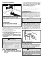
For a temperature controlled instantaneous water heater it
is recommended to install the plumbing as shown in Figure
2. It is also recommended to set-up and control the IWH outlet temperature to be at least 11°C (20°F) above tank thermostat temperature. The recommended plumbing installation for a tankless coil boiler is shown in Figure 3. In this
case, because the tankless coil boiler is able to control only
the differential between inlet and outlet temperature, the
cold water entering the tankless coil boiler must be tempered with hot water from the storage tank. As there is a
large variety of heat sources and control systems, please
contact your local distributor for the plumbing system to
identify the solution that best suits your application.
Important
1. Ensure the storage tank is level before starting installation.
2. Install a circulation loop as shown using 19mm (3/4 in.)
copper piping.
3. If the heating source is a tankless coil boiler go to step
4. If a temperature controlled IWH is used as a heat
source, install the combination inlet/drain valve in one
“arm” of a tee connected to the lower storage tank fitting. Connect the cold water supply piping to the inlet of
the combination inlet/drain valve. Connect the other
“arm” of this tee to the IWH inlet line and place the circulating pump in this line. Connect the IWH outlet to the
upper storage tank side fitting (see Figure 2). Proceed
to step 5.
4. For a tankless coil boiler install the combination
inlet/drain valve in the lower storage tank fitting.
Connect the inlet of the combination inlet/drain valve to
the hot outlet of the tankless coil boiler. In this instance
the “leg” of a tee should connect to the cold water supply line, one “arm” connects to the circulator pump and
the other “arm” to the inlet of the tankless coil boiler. The
circulator pump connects to the upper side fitting.of
storage tank (see Figure 3).
COLD
HOT
MIXING
VALVE
TEMPERATURE
CONTROLLED
IWH
T&P
VALVE
STORAGE
TANK
Do not apply heat directly to tank fittings when making
sweat connections. They contain non-metallic material.
HOT
WATER
T
DRAIN
NOTE ORIENTATION
OF J-TUBE
CIRCULATOR
PUMP
EXPANSION TANK
(OPTIONAL)
CHECK
VALVE
COLD
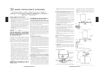
Figure 2 Single Storage Tank Plumbing for a
Temperature Controlled IWH
T&P VALVE
CHECK VALVE
PIPE INSULATION
FROM IWH
CIRCULATOR
PUMP
COLD
HOT
EXPANSION TANK (OPTIONAL)
MIXING
VALVE
COLD
THERMOSTAT
WITH HIGHLIMIT SWITCH
TO IWH &
CIRCULATOR
PUMP
T&P VALVE
HOT
STORAGE
BOOSTER
TANK
T
DRAIN PAN
FLOOR DRAIN
PRESSURE
REGULATOR
(OPTIONAL)
DRAIN VALVE
COLD IN
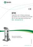
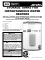
Figure 1 Main Parts and Features for Connection to a
Temperature Controlled IWH
COMBINATION
INLET/DRAIN VALVE
NON-TEMPERATURE CONTROLLED TANKLESS COIL BOILER
Figure 3 Single Storage Tank Plumbing for a NonTemperature Controlled Tankless Coil Boiler
-4-
5. Pay attention to the desired flow direction when
installing the circulator pump. If the pump does not have
a check valve embedded install one to ensure the
desired flow direction is maintained during system operation.
6. Install a mixing valve with the hot port going to the top
tank fitting. Connect the domestic hot water supply line
to the mixing port of the mixing valve. Connect the cold
port of the mixing valve to the cold water supply line and
place a shut-off in this line. Most mixing valves do not
operate properly if the pressure differential between hot
and cold port is too high. If this happens, lower mixed
water temperature will be provided. The shut-off valve
should be used to adjust this pressure differential. Set
the mixing valve outlet temperature to 49°C (120°F) to
avoid scalding.
7. A check valve may be installed in the cold water line
before the connecting tee.
NOTE: The check valve can often be noisy and cause
reduced supply pressures. For multiple storage tank systems, check valves must be installed to prevent the circulator pump from pumping hot water into another tank and
overheating it.
8. The use of a pressure regulator is optional, but recommended when the cold supply pressure is over 80 psi.
Reducing the inlet pressure to 45-60 psi will reduce
probability of relief valve discharge due to thermal
expansion.
9. The water utility supply meter may contain a check
valve, back-flow preventer or water pressure-reducing
valve. This will create a closed water system. During a
heating cycle, water expands creating a pressure
buildup in the water system. A Temperature and
Pressure (T&P) Relief Valve must be installed (150 psi
maximum pressure). See preceding section. If the T&P
valve discharges periodically, it may be due to thermal
expansion in a closed system. To prevent this condition
and to reduce the possible buildup of lime on the T&P
Relief Valve seat, install a thermal expansion tank in the
circulating loop as shown in Figure 2 and 3.
10. Some jurisdictions require a Vacuum Relief Valve to be
installed. Such a valve allows air to enter the piping system thus preventing vacuum conditions that could
siphon water from the system. Check local code
requirements.
GROUND
JUNCTION BOX
(AT CASING TOP)
N
CIRCULATOR PUMP
(FIELD PROVIDED)
WHITE
BLACK
1
3
2
4
1
BLACK
2
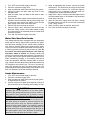
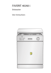
Figure 4 Wiring Diagram
4. The thermostat is rated for a maximum inductive current
of 7 FLA at 120 VAC. Do not exceed this rating for the
circuit.
5. Do not install or connect electrical heating elements to
this tank.
Filling
NOTE: When filling, avoid water leakage. Do not allow the
insulation of the tank to get wet as water can cause electrical malfunction or reduce the effectiveness of the insulation.
1. To insure complete filling of the tank, allow air to exit by
opening a hot water faucet that is served by the tank
and is some distance away from the heater.
2. Ensure the storage tank drain valve is closed.
3. Open the cold water supply valve and fill the tank and
piping system with water. When an uninterrupted
stream of water, without apparent air bubbles, flows
from the open hot water faucet, the system is full.
4. Close the open hot water faucet. Check the system for
leaks, repair as necessary and retest.
5. Connect a hose to the drain valve and route to a suitable drain. Open the drain valve and let water run to
flush out any foreign matter that may have entered the
system. Once flushed, close the drain valve and disconnect hose.
Electrical Wiring
Electrical wiring must be in accordance with local codes or,
in the absence of such codes, with the “Canadian
Electrical Code, Part I, (C22.1)” or the “National
Electrical Code, (NFPA 70)” as applicable.
1. Supply 110/120 volts, 60Hz power, to the junction box
located at the top of the tank.
2. Connect the circulator pump in series with the thermostat as shown in Figure 4.
3. A ground wire must be supplied from the ground connection at the service panel to the ground screw at the
junction box.
L
IV) OPERATION
1. Follow boiler or instantaneous water heater installation
and operating instructions.
2. Fill the tank (see “Filling” section).
3. The boiler or instantaneous water heater should be set
to provide at least 11°C (20°F) higher water temperature
than the temperature setting of the storage tank.
4. Turn power on, check for proper operation of boiler or
instantaneous water heater and storage tank.
-5-
Temperature Adjustment
2. If at the end of the recovery cycle, the IWH is OFF but
the circulator pump does not turn OFF automatically,
reduce the storage tank thermostat set point until the
pump shuts off. Check that pump is off.
DANGER
Temperature Limit Control
For safety, a non-adjustable high limit temperature switch
will shut off the power when excessive water temperatures
are reached. This switch must be re-set manually.
V) MAINTENANCE
Temperature and Pressure Relief Valve
Manually operate the temperature and pressure relief valve
at least once a year to make sure it is working properly. To
prevent water damage, the valve must be properly connected to a discharge line that terminates at an adequate drain.
Water temperature over 52°C (125°F) can cause
severe burns instantly or death from scalds.
Children, disabled and elderly are at highest risk of
being scalded.
CAUTION
The out-flowing water is hot. Avoid splashing the water on
yourself or on the surroundings where it may cause damage.
See instruction manual before setting temperature
at the storage tank.
Feel water before bathing or showering.
Temperature limiting valves are available, see manual.
Thermostats are factory set at 140°F (60°C). The thermostat operates automatically. It can be adjusted to provide a
higher or lower water temperature.
If water temperature adjustment is required:
1. Turn the electrical supply "OFF".
2. Remove the access door and insulation pad.
3. Check with a voltage tester at terminal 1 and 3 of the limit
control that power is indeed "OFF".
4. Adjust the thermostat to the water temperature desired.
5. Ensure insulation pad is in the door cavity. Replace
access door(s).
6. Turn the electrical supply "ON".
Standing clear of the outlet (discharged water may be
hot), slowly lift and release the lever handle on the temperature and pressure relief valve (see Figure 5) to allow the
valve to operate freely and return to its closed position. If the
valve fails to completely reset and continues to release
water, immediately turn "OFF" the electrical supply to the
tank, close the cold water supply valve and call a qualified
service technician.
TEMPERATURE AND
PRESSURE RELIEF VALVE
MANUAL RELIEF VALVE
WARNING:
Risk of scalding
DISCHARGE LINE TO DRAIN
There is a hot water scald potential if the thermostat is set
too high.
Adjusting the thermostat past the 49°C (120°F) bar on the
temperature dial will increase the risk of scald injury. Hot
water can cause severe burns in:
1 1/2 seconds at. . . . . . . . . . . . . . 66°C (150°F)
3 seconds at . . . . . . . . . . . . . . . . . 60°C (140°F)
20 seconds at . . . . . . . . . . . . . . . . 54°C (130°F)
Figure 5 T&P Relief Valve Test
Draining and Flushing
It is recommended that the storage tank be drained and
flushed every 6 months to remove sediment that may build
up during operation. The storage tank should also be
drained if being shut down for extended periods of time. To
drain the tank, perform the following steps:
CAUTION
Initial Temperature Adjustment
1. For the temperature controlled IWH, ensure the temperature set point is 11°C (20°F) higher than the storage
tank set point.
-6-
The water being drained can be extremely hot! The
drain hose should be rated for at least 93°C (200°F). If the
drain hose does not have this rating, open the cold water
supply valve and a nearby hot water faucet served by the
system until the water flow is no longer hot. Close the cold
water supply valve and resume.
1.
2.
3.
4.
5.
6.
7.
8.
9.
Turn "OFF" the electrical supply to the tank.
Close the cold water supply valve.
Open a nearby hot water faucet served by the system.
Connect a hose to the drain valve and route it to an
adequate drain.
Open the drain valve and allow all the water to drain
from the tank.
Open the cold water supply valve and flush the tank as
needed to remove sediment and any other foreign matter that may have entered the system. Close the cold
water supply valve when clean water flows.
Perform any other servicing as required.
Close the drain valve, disconnect hose and refill the
tank (see “Filling” section). If the water heater is going
to be shut down for an extended period, the drain valve
should be left open.
Turn "ON" the electrical supply to the tank.
5. Using an adjustable pipe wrench, remove the anode
and inspect it. The surface may be rough, full of pits and
crevices, but this is normal. If it is less than approximately 6mm (1/4 in.) in diameter, or the inner steel core
is exposed, the anode should be replaced.
6. Apply TeflonTM tape or sealing compounds approved for
use with potable water, to the threads of the anode and
install into the tank top.
7. Open the cold water supply valve and open a nearby
hot water faucet to purge air from the tank as directed
in the “Filling” section.
8. Check for leaks, repair as required, and re-test.
9. Turn "ON" the electrical supply to the tank.
Water Odor/Sacrificial Anode
Your storage tank has been equipped with one magnesium
anode that will slowly deplete while protecting the glasslined tank thus prolonging its life. Certain water conditions
may cause a reaction between the anode and the water.
The most common complaint associated with the anode is
a “rotten egg smell” produced by the presence of sulfur. Do
not remove this anode permanently as it will void any
warranties, stated or implied. An aluminum anode may
reduce if not eliminate water odor problems. The water supply system may require special filtration equipment from a
water conditioning company to successfully eliminate all
water odor problems. Artificially softened water is exceedingly corrosive because the process substitutes sodium ions
for magnesium and calcium ions. The use of a water softener may decrease the life of the water heater tank. The
anode should be inspected periodically. If the anode is more
than 50% depleted, the anode should be replaced.
Anode Maintenance
1. Turn "OFF" the electrical supply to the tank.
2. Close the cold water supply valve.
3. Open a nearby hot water faucet served by the system
to depressurize the system.
4. Connect a hose to the drain valve and drain 22 litres (6
gal.) as directed in the “Draining and Flushing” section.
CAUTION
Hydrogen gas can be produced in a hot water system
served by this storage tank that has not been used for a
long period of time (generally two (2) weeks or more).
Hydrogen gas is extremely flammable and can ignite
when exposed to a spark or flame. To reduce the risk of
injury under these conditions, it is recommended that the
hot water faucet be opened for several minutes at the
kitchen sink before using any electrical appliance connected to the hot water system. Use caution in opening
faucets. If hydrogen is present, there will probably be an
unusual sound such as air escaping through the pipe as
the water begins to flow. There should be no smoking or
open flame near the faucet at the time it is open.
-7-
~ Certificate of Warranty ~
Warranty Code:
See Rating Label Serial Number prefix for
Warranty Code. Reduced warranty period
applies to Newfoundland.
Standard Warranty Years:
Reduced Warranty Years:
P R S T U V W
3 5 6 7 8 9 10
2 3 3 5 5 5 5
Y
12
7
For its GSW and John Wood water heaters and storage boosters ("Unit"), GSW Water Heating ("GSW") warrants that, upon
receipt of a properly verified Warranty claim within the Warranty Period, it will, at its election, repair or replace: units which leak or parts which are defective
in material or workmanship, subject to the terms and conditions set forth in this certificate. GSW will not assume any expense or liability for unauthorized
returns, nor repairs made by a person who has not been authorized by GSW or one of its authorized dealers. GSW Units/parts must be replaced with GSW or
John Wood products to be eligible for Warranty. This Warranty is available to the original owner of a Unit installed within the boundaries of continental United
States, of Canada, or their territories. Consumers must retain point-of-sale proof of purchase to validate warranty entitlement. This Warranty does not
cover components not manufactured by GSW, such as oil burners, which carry the warranty given by the manufacturer thereof, copy of which warranty GSW
will make available, to the extent supplied by the manufacturer, without recourse to GSW.
THERE ARE NO WARRANTIES WHICH EXTEND BEYOND THE DESCRIPTION ON THE FACE HEREOF. THIS EXPRESS
WARRANTY IS, WHERE PERMITTED BY LAW, IN LIEU OF AND EXCLUDES AND REPLACES ALL OTHER CONDITIONS,
WARRANTIES, GUARANTEES, REPRESENTATIONS, OBLIGATIONS OR LIABILITIES OF GSW OF ANY NATURE OR KIND,
EXPRESS OR IMPLIED, HOWEVER ARISING (WHETHER BY CONTRACT, CONDUCT, STATEMENT, STATUTE, NEGLIGENCE, PRINCIPLES OF MANUFACTURER'S LIABILITY, OPERATION OF LAW OR OTHERWISE) WITH RESPECT TO THE
UNIT OR ITS FITNESS FOR A PARTICULAR PURPOSE, MERCHANTABILITY, INSTALLATION, OPERATION, REPAIR OR
REPLACEMENT. GSW EXPRESSLY DISCLAIMS ANY AND ALL IMPLIED WARRANTIES. IN NO EVENT WILL GSW'S LIABILITIES EXCEED THE COST OF THE DEFECTIVE PART(S) OR UNIT. GSW WILL NOT PAY FOR ANY TRANSPORTATION,
LABOUR, INSTALLATION, OR OTHER INCIDENTAL COSTS ASSOCIATED WITH THE REPAIR OR REPLACEMENT OF A
DEFECTIVE PART OR UNIT.
This warranty and GSW's obligations shall be construed and determined in accordance with the laws of both the Province of Ontario, and of Canada in force
therein. This Warranty does not affect specific legal rights of a consumer under applicable law, except to the extent that such rights may be waived or replaced,
and the provisions hereof are deemed to be amended to the extent necessary. The unenforceability of any provision, in whole or in part, of this Certificate shall
not affect the remaining provisions. Any and all repair and/or replacement of part(s) or Unit are the sole and exclusive remedy available against GSW.
LIABILITY OF GSW COVERED BY THIS WARRANTY IS CONDITIONAL UPON THE FOLLOWING:
1.
2.
3.
4.
5.
6.
The Unit shall be installed in accordance with all manufacturers' instructions, all applicable equipment and building codes, ordinances and regulations (hereinafter referred to as the "standards").
The Unit must not be installed where water damage can result from a
leak, while provision(s) shall be made for directing any water escaping
from the Unit, to a properly operating drainpipe. As all units of this type
may eventually leak, you must protect against any potential water damage. GSW accepts no responsibility for such damage, nor any incidental
or consequential loss, nor damage(s) related thereto, suffered by the
owner of the Unit nor by any third party.
The Unit shall not be installed where it will be exposed to adverse or
unusual environmental or corrosive conditions. No warranty extends, for
example, and without limitation of the foregoing, to Units exposed to:
salts; chemicals; exhausts; pollutants or contaminants. Further, no warranty extends to Units affected by fire, freezing or flood, "Acts of God",
or any other contingency beyond the control of GSW.
The Unit shall be equipped with a properly operating temperature and
pressure relief valve as specified by GSW and applicable standards. The
Unit shall be operated at temperatures not exceeding the maximum setting of the thermostat and/or high limit control provided by GSW, and at
water pressures not exceeding the pressure reading stated on the Unit.
The Unit must be carefully inspected, maintained, and operated in accordance with the manufacturer's instructions. No warranty extends, for
example, and without limitation of the foregoing, to any Unit operated:
without the tank being completely filled with water; without an operating
anode; with levels of sediment or lime precipitate which cause failure; in
connection to any attachment(s), energy saving device(s), or other means
of heating, except as approved by GSW for the Unit; other than with
potable water without any additives such as salts, chlorine or chemicals,
except those added for the sole purpose of rendering the water fit for
domestic use.
All repairs must be made by a competent and qualified person who is certified, by GSW or one of its authorized dealers, to work on the Unit, using
factory approved replacement parts, and the Unit shall not be otherwise
modified, altered or improperly repaired.
7.
8.
9.
-8-
A properly documented claim shall be received by GSW or one of its
authorized dealers, or point of purchase, within the following Warranty
Period, except as provided otherwise below*:
a) for any defective part, within one (1) year; or
b) for any Unit that develops leaks in the inner tank due to rust, corrosion
or other chemical reactions caused by the potable domestic water supplied to your home, within the period of time shown in table at the top of
this page.
* Residential units installed and used in a commercial application carry a
warranty period of one (1) year from date of installation; and,
Any repair or replacement of any part, tank, or Unit under this Warranty
will not extend the Warranty Period beyond that calculated from the date
of first installation of the original Unit. The date of first installation will
be deemed to be the later of the date indicated by the Unit's serial number, or if supplied with the Warranty claim, the sales receipt, or installer's
receipt.
A claim under this Warranty must include the model and serial number of
the Unit, proof of date on which the Unit was first installed, and the identity of the defective part(s) for which a claim is being made and be submitted within 15 days following discovery of the defect(s), by personal
delivery to a GSW authorized dealer, point of purchase, or GSW itself at:
GSW Water Heating
GSW Water Heating is a division of GSW Water Products Inc.
599 Hill Street West
Fergus, ON Canada N1M 2X1
Should you have questions, please call our Technical Support Line at 1888-479-8324.
If requested by GSW, information relating to the purchase, transportation,
operation and installation of the Unit must be supplied. The defective
part(s) or Unit, with all components properly and securely packed, shall
be returned transportation pre-paid, to the address designated by GSW in
the written request. All claims are subject to validation by GSW.