1
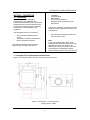
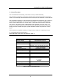
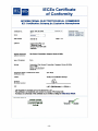
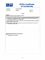
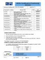
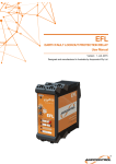
CO2 Infra Red Transmitter/ Sensor
Units
Designed and Manufactured in Australia
by Ampcontrol Pty Ltd ABN 35 000 770
141 Phone: (02) 4903 4800 Fax: (02)
4903 4888 www.ampcontrol.com.au
USER MANUAL
No copies of the information or drawings
within this manual shall be made without
the prior consent of Ampcontrol.
161296
Gasguard CO2 IR 04-09-2012
Copyright Notice
No part of this publication may be
reproduced, transmitted or
transcribed into any language by any
means without the express written
permission of Ampcontrol Pty Ltd, 7
Billbrooke Close, Cameron Park
NSW 2282, Australia.
Disclaimer
Ampcontrol Pty Ltd will make no
warranties as to the contents of this
documentation and specifically
disclaims any implied warranties or
fitness for any particular purpose.
Ampcontrol further reserves the right
to alter the specification of the
system and/or manual without
obligation to notify any person or
organisation of these changes.
Before You Begin
We would like to thank you for
purchasing the Ampcontrol
Gasguard Products. To become
completely familiar with this
equipment and to ensure correct
operation, we recommend that you
take the time to read this user
manual thoroughly.
IMPORTANT WARNINGS AND ADVICE
1. The sensors should not be stored
in areas that contain solvent
vapours. Some of these vapours
are known to create false "high"
zero points and may even damage
the sensor electrodes. Similarly,
the sensor should not be exposed
to high levels of solvent vapours
while in operation.
2. This equipment has been
designed to detect hazardous
gases and vapours and to give
warning before they reach
dangerous conditions. In order to
ensure that the equipment will
warn of dangerous situations it is
essential that the instructions in
this manual be read, understood
and followed. It is further stressed
that the effectiveness of the
device depends heavily on the
user who is responsible for its
correct application, use and
regular maintenance.
3. During start up, infra-red sensors
will display a fault condition for
approximately one minute before
stabilising.
GASGUARD CO2 SENSOR USER MANUAL
SECTION 1 - DESCRIPTION
1.1 Introduction........................................
SECTION 4 – MAINTENANCE
4.1
4.2
1
1.1.1 Gasguard Transmitter/Sensor Unit
Dimensions.............................................. 1
1.1.2 General Description………..………. 2
1.1.3 Specification………………….…….. 2
Periodic Maintenance.................. 11
Corrective Maintenance ….......... 11
SECTION 5 - EQUIPMENT LIST
Appendix……………………………...……….. 13
1.2 Sensors............................... 3
Certificate of Conformity……….……….. 13
1.2.1 Carbon Dioxide Gas Sensors.......... 3
1.2.2 Humidity.......................................... 3
1.2.3 Pressure Effects.............................. 3
1.2.4 Operational Restrictions.................. 3
Document Revision History
1.3 Amplifier PCB..................................... 3
Revision
Rev0
Rev1
1.3.1 Infra-Red Amplifier PCB.................. 3
1.4 Enclosures..........................................
Date
03-06-2008
04-09-2012
Comment
Initial issue
Cert. Update
4
1.4.1 Stainless Steel Housing.................. 4
1.5 Sensor Wiring Assembly.......... 4
1.5.1 Connections……………………..….. 4
1.5.2 Anti-Vibration Clip………………..… 4
SECTION 2 – INSTALLATION
2.1 Installation Guidelines ................... 5
2.2 Relative Density ............................ 5
2.3 Cable Resistance
Considerations......................................... 5
2.4 Earthing Procedures ..................... 5
2.5 Wiring............................................ 5
SECTION 3 – COMMISSIONING
AND CALIBRATION
3.1
3.2
3.3
3.4
3.5
3.6
Introduction.................................... 8
Preliminary Checks........................ 8
Gasguard Display Panel ............... 8
System Calibration ........................ 8
Zero Calibration............................. 9
Span Calibration............................ 9
-1-
CONTENTS
GASGUARD CO2 SENSOR USER MANUAL
SECTION 1 - DESCRIPTION
1.1 Introduction
•
•
•
•
•
This manual provides installation,
commissioning, and calibration and
maintenance instructions for the Ampcontrol
Gasguard Sensor Units. Because the units
are passive monitoring devices, operating
instructions are not applicable to this
equipment.
Installation
Commissioning
Maintenance
Sensor Wiring Diagrams
Stainless Steel Housing Enclosure
Dimensions
Unique part numbers in accordance with the
following scheme identifies the sensor unit
configurations:
This Gasguard sensor unit consists of:
•
•
•
•
Infra-red Carbon Dioxide Sensor
(CO2)
Transmitter Amplifier PCB Assembly
IP 66 Transmitter Enclosure
Part Number 65-6552XXX series is for
Infra-red sensor units.
Note:
In the part numbers listed above, XXX
represents the chemical symbol for the gas
detected by the unit. For example, 656552CO2-2 is the part number for an Infrared transmitter unit designed to detect
Carbon Dioxide (CO2) in the range of 0 -2%.
For which the following instructions and
diagrams are included in this manual:
1.1.1 Gasguard CO2 Transmitter/Sensor Unit Dimensions
Figure 1.1 shows the bottom and front view of the Infra-red Sensor.
Figure 1.1 Dimensions – Infra-red Sensor
Weight approx. 3.8KG
-1-
GASGUARD CO2 SENSOR USER MANUAL
1.1.2 General Description
The Transmitter/Sensor assembly is an IEC Ex ia Group I certified assembly.
The Certification is based on the unit being sealed to IP 66 and the appropriate checks being
made on the Intrinsically Safe Parameters of the overall system the transmitter is connected into.
The Transmitter and Sensor can be mounted as an integral device but there is also an option to
mount the sensor separately up to 10m from the transmitter. In the remote configuration the
sensor is factory fitted with a type 2S cable which is potted directly into the sensor assembly.
The sensor is designed to provide a standardised output applicable for the gas range. This
signal is not for direct connection to other devices and so the amplifier PCB in the transmitter
housing is used to condition the signal, provide calibration functions and produce a 4-20mA
signal.
The transmitter and amplifier assembly is configured in the factory for a specific gas range.
1.1.3 Transmitter / Sensor Specifications
Specification data for the sensor is contained in Table 1.1.
GAS
Detection Method
Maximum Range
Overall Linearity
Maximum Drift
CO2
Non Dispersive Infra-red
0- 2% or 0- 5%
<± 5% of Full Scale
Zero, <±2.5% of Full Scale per month
Sensitivity, <±5% of Full Scale per month
Repeatability
Response Time (T90)
Infra-red Lamp Life
Resolution
Humidity (RH nonTemperature Range,
Operation &
<± 2.5% of Full Scale
<45 Seconds (Typical)
>5 Years
0.01%
0 – 90%
-10 to + 60° C
Power Requirements.
Input Parameters J5
12VDC @ 100mA
Ui=16.5V
Li=10.35µH
Ci=40nF
Voltage Range
Warm up time
Warranty
10 – 16.5V DC
10 minutes
1 Year
Table 1.1 Sensor Specification Data
-2-
GASGUARD CO2 SENSOR USER MANUAL
The Amplifier PCB requires a 12VDC
operating voltage and transmits a signal of
4-20mA. At the lower end of the range, the
4mA signal level indicates a zero gas
concentration. At the upper end of the
range the 20mA signal indicates that the
sensor has detected a full span gas
concentration. ZERO and SPAN
adjustment reed relays located on the PCB
are used for calibration of the instrument.
1.2 Sensor
1.2.1 Carbon Dioxide Gas Sensor
The Carbon Dioxide Gas Sensor works on
the infra-red gas absorption principle. An
infra-red light source illuminates the sensor
through a gas pathway with an optical filter
that selects the appropriate wavelength for
the gas being detected; the presence of
this gas reduces the amount of infra-red
energy reaching the detector. This
difference in infra-red energy with and
without gas is used to measure the amount
of gas present, and is converted to an
electrical output of 4–20mA by the
amplifier electronics.
1.2.2 Humidity
Sensors cannot operate in a condensing
atmosphere. In such an environment, a
thin film of water can form across the
membrane, effectively sealing it and
stopping the passage of gas into the
sensor. On evaporation of this water the
sensor usually resumes normal operation.
Above 90% R.H. the sensor accumulates
water vapour and may form condensation
to block the infra-red path used for gas
detection. Provided the exposure to these
extremes of humidity has not been for a
long period, the sensors will recover when
exposed to R.H. in the range 15% to 90%.
1.2.3 Pressure Effects
The infra-red sensors do not exhibit a
permanent response to changes of
pressure. The CO2 sensor responds to
pressure on a directly proportional basis.
1.2.4 Operational Restrictions
For proper operation, infra-red detectors
need to be in a position which is free from
damaging vibration and within the
temperature range of -10C to +60C.
1.3 Amplifier PCB
1.3.1 Infra-Red Amplifier PCB
The purpose of the Amplifier PCB is to
convert the low- level electrical output of
the sensor into a signal capable of driving
various types of external indicator
equipment such as the Ampcontrol
Gasguard 4 Channel Controller.
-3-
GASGUARD CO2 SENSOR USER MANUAL
1.4 Enclosures
1.4.1 Stainless Steel Housing
The standard Stainless Steel Housing,
Part Number 105994 (shown in Figure
1.1), incorporates the I/R Sensor and
Amplifier PCB. The housing is robust and
is corrosion resistant. It is suitable for
almost all applications and provides for
easy installation and maintenance. When
properly used it gives many years of
efficient operation.
1.5 Sensor Wiring Assembly
1.5.1 Connections
Electrical connections for the sensor are
by means of a shielded cable from the
Sensor Assembly 105997.
A sensor wiring assembly provides the
electrical interface between the sensor and
the Amplifier PCB. The sensor wiring plugs
into the Amplifier PCB connector J4.
A second wiring assembly connects the
customer supply and signal connections
from the incoming terminals to the
Amplifier PCB connector J5.
The Sensor and Amplifier assemblies are
intrinsically safe items and as such are
only serviceable by authorised factory
personnel.
See Figure 2.1 Section 2, Page 6 for wiring
details.
Figure 1.2 Anti-Vibration Clip
Note:
Only sensor assembly 105990 may be
connected to the main amplifier in this unit.
Connection of any other type of sensor
head will render the unit non-operational.
Customers should ensure that the correct
range Sensor and Transmitter assemblies
are matched together.
1.5.2 Optional Anti-Vibration Clip
An optional Anti-Vibration clip Pt/No.
121647 can be fitted to the connectors J4
& J5 on the rear of the Amplifier PCB.
This is only needed in areas of high
vibration.
-4-
GASGUARD CO2 SENSOR USER MANUAL
SECTION 2 - INSTALLATION
2.1 Installation Guidelines
Gas
Ammonia
To ensure continued reliable operation of the
sensor system, the following installation
guidelines should be observed:
•
•
•
•
•
•
LIGHTER
THAN AIR
Methane
Carbon Monoxide
Carbon Dioxide
Confirm the Intrinsically Safe parameters
of the transmitter, cables and power
supply are suitable for the application.
Select a suitable central location for
mounting with good access. The location
should be as clean and dry as
practicable and at a temperature as
close to 20°C as practicable.
Mount the sensor unit in a position that
reduces the risk of mechanical damage.
Mounting should be to a vertical surface,
pointing downwards, allowing for easy
wiring access and subsequent servicing.
It is essential that the sensor be
positioned to take into account the
expected flow of the gas to be
measured.
Allow sufficient space under the sensor
for fitting of calibration cups or
accessories.
Nitric Oxide
Oxygen
Hydrogen Sulphide
HEAVIER
THAN AIR
Chlorine
Nitrogen Dioxide
Table 2.1 Gas Density
2.3 Cable Resistance Considerations
The Infra-red Amplifier PCB output is 4-20mA
current. The voltage available to the amplifier
must be a minimum of 10VDC. With a supply
voltage of 12VDC the maximum cable
resistance, both +ve & -ve leads combined, is
16 Ohms. The maximum resistance in the 420mA signal to ground at 12V DC supply is
200 Ohms. See Table 2.2 for typical cable
resistance values.
Conductor Area
mm2
0.5
2.2 Relative Density
The relative density or buoyancy of the gas or
vapour with respect to air determines its
propensity to rise or fall when released into
the atmosphere.
Gases or vapours with buoyancy less than air
will tend to rise from the source of release.
Conversely, gases or vapours heavier than air
will tend to fall and accumulate in
concentrations over long periods of time.
Normal air movements in and around such
gas concentrations will have the inevitable
effect of producing zones of highly toxic
mixtures.
This knowledge of the characteristics of the
gas assists when determining the location of
the gas sensor. See Table 2.1 for gas density
values.
For monitoring of heavier-than-air gases,
mount the sensor as close as practical to the
floor or ground. For monitoring of lighter than
air gases, install the sensor unit as high as
practical.
The services of a Risk Assessment Engineer
or specialist should be used if additional
assistance is required in selecting the position
of, or the number of sensors required for the
application.
Density
Hydrogen
1
1.5
2.0
2.5
Loop
Resistance
6.71
3.36
2.24
1.72
1.38
Table 2.2 Nominal Resistance Values for
Wire Sizes
2.4 Earthing Procedures
Consideration should be given to the earthing
of the transmitters and cable screens of the
incoming customer cables.
Normal practice would be to isolate the cable
screens at the Transmitter and connect the
screens to earth adjacent to the Control units
or power supply to the system.
Remote sensor cable screens should be
earthed at the transmitter.
2.5 Wiring
Figure 2.1, Page 6 shows the wiring of the
infra-red transmitter with built in Sensor.
Figure 2.2 details the Remote head version.
-5-
GASGUARD CO2 SENSOR USER MANUAL
Figure 2.1 Infra-red Sensor Unit Wiring Diagram
-6-
GASGUARD CO2 SENSOR USER MANUAL
Figure 2.2 Remote Infra-red Sensor Unit Wiring Diagram
-7-
GASGUARD CO2 SENSOR USER MANUAL
SECTION 3 - COMMISSIONING AND
CALIBRATION
3.1 Introduction
Description
-777
There is no sensor
plugged into the amplifier
-999
Er
CAL
Commissioning is the performance of initial
checks, adjustments and calibration prior to
placing the system in operation for the first
time. Calibration, however, is not limited to
performance of commissioning. Calibration
is also performed throughout the life of the
system on a periodic basis and after major
repairs to the system.
During commissioning and subsequent recalibration, it is vital to ensure that
procedures are followed to prevent any
abnormal sensor signal from initiating any
fault, warn or alarm status indicator or
equipment control function, on auxiliary
equipment connected to the transmitter.
Consult the relevant control unit manual for
details of how to do this.
The instruments supplied are NATA
calibrated prior to delivery. However, before
putting the system into operation, it is
recommended to check the calibration. This
is especially important if the instruments
are commissioned some time after delivery.
SAU
PU/Ir
Amplifier needs reconfiguration
Error has occurred
Calibration mode initiated
(display blinks when in calibration
mode)
Calibration settings have been
saved
Powering Up - Infra-red Unit
Table 3.1
3.4 System Calibration
Before the start of calibration, the system
should be left in a powered-up operational
(no fault) state for one hour to allow the gas
sensors to stabilise. However, if such a
delay is not practical, observe the display
indications with the sensor in a gas free
atmosphere, until there is no appreciable
display movement for a period of time. The
system should then be sufficiently stable
to allow calibration. During calibration,
avoid breathing over unit, since carbon
dioxide from exhaled breath will affect the
readings.
3.2 Preliminary Checks
•
Perform the following preliminary checks:
a) Verify that all connections are correct
and installation complete as detailed in
Section 2.
b) Check that voltage available to the
amplifier is 12VDC
c) Apply power to the system.
Note: Following initial application of input
power the display will alternate between
PU & Ir for approx. 10 secs while it warms
up, to show the unit is Infra-red. The output
is held at a nominal 4mA during this
period, after which it displays -0.46 for up
to 30 seconds before reading zero +/0.05% (Providing no gas is present).
•
•
3.3 Gasguard Display Panel
To assist in fault finding the Gasguard display
panel will indicate the following:
Display
-8-
Calibration of sensors can only be
achieved by using the appropriate
gas. That is the gas that the sensor is
designed to detect. A calibration gas
should be 50% of full scale of the
relevant monitor.
For gas detection, if reading
inaccuracies cannot be avoided,
sensors should always be calibrated
on the high side for safety reasons.
Calibration gas should be applied to
the sensor at a rate of approximately
0.5 to 1.0 litre per minute, using the
Calibration Cup. Allow sufficient time,
usually about 2 minutes, for sensor to
stabilize before adjustment.
GASGUARD CO2 SENSOR USER MANUAL
Figure 3.1 Gasguard CO2 Control Panel
3.5 Zero Calibration
Perform Zero Calibration as follows:
a) Ensure that the sensor is in a fresh air environment, and apply High Purity Nitrogen via
the Calibration Cup.
b) Place the magnetic tip of the calibration pen over the CAL symbol (1) for 5 seconds. The
display will flash every 1-2 seconds while in calibration mode.
c) Now that the CAL mode is accessed place the magnetic tip over the ZERO symbol (3) for
2-3 seconds.
d) The display should have changed to a zero reading. To save the zero setting place the
magnetic tip over the CAL symbol (1) for 5 seconds.
e) The sensor display (5) will show SAU to confirm that it has saved the zero setting. The
display will cease to flash.
3.6 Span Calibration
Perform Span Calibration as follows:
a) Apply CO2 calibration gas to the sensor at the rate of 0.5 to 1 litre per minute. Use a
calibration gas of suitable concentration between 1% to 2% CO2 for the 2% range unit or
2.5% to 5.0% for the 5% range unit.
b) To adjust the display so that it reads the correct value for the gas applied enter
Calibration Mode by placing the magnetic tip of the Calibration pen over the CAL symbol
(1) for 5 seconds. The display will flash every 1-2 seconds.
c) Place the magnetic tip of the pen over the UP symbol (4) to increase the display reading
and over the DOWN symbol (6) to decrease the display reading.
Place the magnetic tip over the CAL symbol (1) for 5 seconds once the display reads the
correct value for the gas applied. The display will cease to flash.
d) Shut off the calibration gas. If the Zero calibration is to be checked, wait for the sensor to
stabilise before proceeding.
Note: Human breath contains a high concentration of CO2 and this may cause the instrument to
read above zero.
-9-
GASGUARD CO2 SENSOR USER MANUAL
3.6.1 Calibration Problems
Gasguard Sensor/Transmitter Fault Codes.
Refer Table 3.1
If during calibration or zero of the Gasguard CO2 Transmitter the fault indication on the local
display is shown as “ERR” then possible reasons are as follows:
1. Calibration
If the fault code appears during calibration it will normally be when adjustment by the Up or Down
arrows is attempted. The code indicates that the output of the sensor is insufficient and the sensor
will need to be changed.
Several things should be checked before changing the sensor.
a) Check the calibration gas. It should be a correct range in air mixture although other trace
gases may be present. Lower percentage gas mixtures will reduce the output leading to
unnecessary change out of the sensor.
b) Check the gas flow to ensure it is within 0.5 to 1.0 Litres/min.
c) Check the surrounding airflow. If the ambient air flow is above 1.5 Metres/sec it can dilute
the calibration gas. Use a shield or bag over the sensor if there is a high wind speed.
d) Check sensor is not blocked with dust or mud. The sensor can be washed out and
calibration carried out after drying.
e) If all the above are OK and confirmation of sensor output is required it can be measured
with a DVM.
The signal voltage developed at the sensor can be measured at the third terminal from the
left on the four way plug marked “Sensor” on the back of the amplifier board. With zero gas
present this voltage should be 1.9 +/-0.05VDC measured with respect to 0V. With full span
gas applied this voltage should rise to around 2.1 +/-0.05VDC. If this change in voltage
cannot be achieved then the sensor may need to be replaced.
2. Zero
The sensor zero balance is required to be within a preset level and if the sensor is damaged the
zero shift may take it outside the limit. Once this occurs the “ERR” indication is shown when
trying to zero the instrument, and the sensor should be replaced.
If during a calibration or zero procedure the instrument fails to complete the process, the original
settings prior to entering Cal mode will be retained. If left in Cal mode the instrument will revert to
normal mode after about 5 minutes, retaining its last settings.
3. Erratic readings
Check the tightness of screw terminals on the connectors and check connectors are pushed fully
home. Fit anti vibration clip if the problem persists.
-10-
GASGUARD CO2 SENSOR USER MANUAL
SECTION 4 - MAINTENANCE
4.1 Periodic Maintenance
Periodic maintenance consists mainly of scheduled checks to ensure the instrument remains in
adjustment and gives the required response to sampled gas. The following maintenance schedule
is recommended.
Daily:
Verify operation by visually checking the reading on the respective control unit/monitor. Investigate
any abnormal deviations from expected background levels.
Monthly:
a) Check the Zero reading in Nitrogen for one minute; re-adjust non zero as necessary.
b) Check the Span calibration on a known sample of CO2 gas in air. Re-adjust as necessary.
As Required:
Replace sensor whenever it becomes impossible to adjust to Zero, or when the Span adjustment
is insufficient to enable adjustment to the calibration gas value. If this occurs, recalibrate the unit
as described in Section 3: Commissioning and Calibration.
Following Power Removal:
If power has been removed from the unit for more than a week, a re-commissioning check should
be carried out.
4.2 Corrective Maintenance
During maintenance it is vital to ensure that suitable procedures are followed to prevent any
abnormal sensor signal from unintentionally operating any fault, warn or alarm status indicator,
or equipment control function. Consult the relevant control unit manual for details as to how to do
this.
There are only two active replaceable units in the sensor system, the Amplifier PCB and the IR
Sensor Assembly. Therefore, fault isolation is limited to the following possible faults and
remedies.
No 4-20mA Output:
a) Check that voltage applied to the Amplifier PCB is 12VDC and that the polarity is correct.
b) Check for loose plug and terminal connections.
c) If Step a) above is correct and the problem persists, replace the Amplifier PCB.
Sensor cannot be Spanned or Zeroed:
a) Check that voltage and polarity applied to the amplifier is correct.
b) Check for loose plug and terminal connections.
c) If the above is correct and the problem persists replace the Sensor.
d) If the sensor still cannot be spanned or zeroed replace the Amplifier PCB.
Erratic Output:
a) Check that voltage and polarity applied to the Amplifier PCB is correct. Also, check that
there are no severe voltage swings, indicating an intermittent fault in the field wiring or
control unit.
b) Check for loose plug and terminal connections.
c) If the above is correct and the problem persists, replace the sensor. d) If the output is still
erratic, replace the Amplifier PCB.
-11-
GASGUARD CO2 SENSOR USER MANUAL
SECTION 5 - EQUIPMENT LIST
Part #
Approval Part #
Description
115239
65-6552CO2-2
Carbon Dioxide Gas Sensor/Transmitter, Range 0 -2% CO2
115240
65-6552CO2-5
Carbon Dioxide Gas Sensor/Transmitter, Range 0 -5% CO2
105997
61-6552CO2-2
CO2 Sensor Head Assy, Range 0 -2% CO2
105997
61-6552CO2-5
CO2 Sensor Head Assy, Range 0 -5% CO2
105441
75-6557LB
Replacement Amplifier
121647
PCB E10051
Anti-Vibration Clip
-12-
-13 -14 -15 -16 -17 -18 -19 -20