1
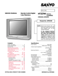
SERVICE MANUAL
Service
Manual
Zusätzlich erforderliche Unterlagen
für den
Komplettservice:
Sach-Nr./Part no.
72010-800.00
OK
TIMER
ON/OFF
SET
CHECK
EW/ED
INSERT
CL
MAN
RECORD LEVEL
L AUDIO IN R
GV 440 VPS
GV 440 NIC
GV 450 VPT
GV 450
GV 440 VPS / NIC
GV 450 VPT / GB / NIC
GV 4592 VPT / Madrid
GV 460 VPT / NIC
Sicherheit
Safety
Additionally required
Service Manuals for
the Complete Service:
Sach-Nr./Part no.
72010-514.90
*
Service
Manual
8
VIDEO IN / CV
(9.27044-03.51 / G.MD 4400) RP 30
(9.27044-09.51 / G.MD 4300) RP 30
(9.27044-02.51 / G.MD 3000) RP 35
(9.27044-07.51 / G.MD 3200) RP 33
OK
TIMER
ON/OFF
GV 450 GB
(9.27044-10.51 / G.MD 2900 GB) RP 33
GV 450 NIC
(9.27044-08.51 / G.MD 3100) RP 35
GV 4592 VPT / Madrid (9.27041-12.51 / G.MD 4100) RP 35
SET
CHECK
EW/ED
CL
U
S-VHS
RECORD LEVEL
INSERT
MIC
GV 460 VPT
MAN
L AUDIO IN R
DUBBING
VIDEO IN / CV
8
U
(9.27044-01.51 / G.MD 3500) RP 35
GV 460 NIC
(9.27044-04.51 / G.MD 3700) RP 35
1
2
4
3
5
6
1
2
3
4
5
6
7
8
9
SET
;
EW/ED
7
8
9
0
;
SAT
EW/ED
SET
OK
SAT
p
AUTO
TRACKING
Ç
Hi-Fi
0000
*
8
:
Ç
HIFI
COUNT
0000
*
8
p
PROGRAM
e
uu
p
PROGRAM
8
J
PROGRAM
AV
HIFI
*
8
p
PROGRAM
+
C
–
AV
P
CODE
RP 35
STORE
w
4
DATE
´
OK
q
RP 33
Änderungen vorbehalten
Subject to alteration
RP 30
Printed in Germany
VK 222/1 1093
+
–
AV
e
+
)
FINE TUNING
–
PICTURE
+
C
NAME
STORE
DATE
P
CODE
VIDEO 1
PAL SECAM
TV
+
–
ATS
SECAM
8
TV
1 VIDEO 2
PICTURE
NAME
PAL/SEC
PAL SECAM
p
AUTO
TRACKING
Ç
0000
+
RP 30
PAL
o
S-VHS
:
COUNT
TV
FINE TUNING
–
ATS
PAL/SEC
AV/CV
e
r
J
9
SAT
V
o
8
6
0
LP
p
AUTO
TRACKING
V
LP
o
2x
ii
o
o
S-VHS
ON/OFF
o
:
COUNT
3
OK
PROGRAM
PROGRAM
TIMER
ON/OFF
V
8
TIMER
AV/CV
RECORD
CL
CHECK
TIMER
LP
–
OK
AV/CV
RECORD
CL
5
7
RECORD
ON/OFF
0
;
EW/ED
SET
2
4
CL
CHECK
CHECK
1
´
VIDEO 2
RP33
TIP
#
<
ATS
PAL/SEC
3
VPT
INFO
VIDEO 1
STOP
P
PICTURE
CODE
VIDEO 2
RP35
Service Manual Sach-Nr. 72010-514.90
Service Manual Part No. 72010-514.90
Allgemeiner Teil / General
GV44…, GV45…, GV46…
Es gelten die Vorschriften und Sicherheitshinweise gemäß dem Service Manual "Sicherheit",
Sach-Nummer 72010-800.00, sowie zusätzlich
die eventuell abweichenden, landesspezifischen
Vorschriften!
D
Inhaltsverzeichnis
The regulations and safety instructions shall be
valid as provided by the "Safety" Service Manual,
part number 72010-800.00, as well as the
respective national deviations.
GB
Table of Contents
Seite
Allgemeiner Teil ................................. 1-1…1-68
Page
General ............................................... 1-1…1-68
Geräteübersicht ............................................................................. 1-3
Meßgeräte / Meßmittel ................................................................... 1-4
Technische Daten .......................................................................... 1-4
Bedienelemente ............................................................................. 1-5
Servicehinweise ........................................................................... 1-61
Servicetestprogramm und Sonderfunktionen ............................... 1-65
Video Recorder Overview .............................................................. 1-3
Test Equipment / Jigs .................................................................... 1-4
Specifications ................................................................................. 1-4
Operating Elements ..................................................................... 1-33
Service Instructions ...................................................................... 1-61
Service Test Programme and Special Functions ......................... 1-65
Beschreibungen .................................. 2-1…2-16
Descriptions ........................................ 2-1…2-16
Netzteil (PS) ................................................................................... 2-1
Chassisplatte ................................................................................. 2-2
• Ablaufsteuerung / Deckelektronik (DE) ....................................... 2-2
• Teletext "DOS" (OS) ................................................................... 2-5
• Empfangseinheit (FE) ................................................................. 2-6
• Video / Chroma (VS) ................................................................... 2-7
• FM-Ton (AF) ............................................................................. 2-10
• Standardton / Audio Linear (AL) ............................................... 2-11
• IN/OUT (IO) ............................................................................... 2-12
NICAM-Decoder (NI) .................................................................... 2-13
Bedieneinheiten (DC) ................................................................... 2-14
Power Supply (PS) ......................................................................... 2-1
Family Board .................................................................................. 2-2
• Sequence Control / Deckelectronic (DE) .................................... 2-2
• Teletext "DOS" (OS) ................................................................... 2-5
• Frontend (FE) .............................................................................. 2-6
• Video / Chroma (VS) ................................................................... 2-7
• FM-Sound (AF) ......................................................................... 2-10
• Standard Sound / Audio Linear (AL) ......................................... 2-11
• IN/OUT (IO) ............................................................................... 2-12
NICAM Decoder (NI) .................................................................... 2-13
Keyboard Control Units (DC) ....................................................... 2-14
Abgleich ................................................ 3-1…3-4
Adjustment Procedures ....................... 3-5…3-8
Netzteil (PS) ................................................................................... 3-1
Chassisplatte ................................................................................. 3-1
• Ablaufsteuerung / Deckelektronik (DE) ....................................... 3-1
• Teletext "DOS" (OS) ................................................................... 3-2
• Empfangseinheit (FE) ................................................................. 3-2
• Video / Chroma (VS) ................................................................... 3-3
• FM-Ton (AF) ............................................................................... 3-4
• Standardton / Audio Linear (AL) ................................................. 3-4
Power Supply (PS) ......................................................................... 3-5
Family Board .................................................................................. 3-5
• Sequence Control / Deckelectronic (DE) .................................... 3-5
• Teletext "DOS" (OS) ................................................................... 3-6
• Frontend (FE) .............................................................................. 3-6
• Video / Chroma (VS) ................................................................... 3-7
• FM-Sound (AF) ........................................................................... 3-8
• Standard Sound / Audio Linear (AL) ........................................... 3-8
Platinenabbildungen
und Schaltpläne ................................. 4-1…4-44
Layout of the P.C.B.
and Circuit Diagrams ........................ 4-1…4-44
Hinweise zu den Bauteilen / Schaltplansymbole ........................... 4-1
Verdrahtungsplan ........................................................................... 4-6
Blockschaltpläne (Analog / Digital) ................................................ 4-8
Netzteil (PS) ................................................................................. 4-12
Laufwerkplatte – Sensoreneinheit ................................................ 4-20
Chassisplatte ............................................................................... 4-15
• Ablaufsteuerung / Deckelektronik (DE) ..................................... 4-18
• Teletext "DOS" (OS) ................................................................. 4-21
• Empfangseinheit (FE) ............................................................... 4-22
• Video / Chroma (VS) ................................................................. 4-24
• FM-Ton (AF) ............................................................................. 4-26
• Standardton / Audio Linear (AL) ............................................... 4-28
• IN/OUT (IO) ............................................................................... 4-30
NICAM-Decoder (NI) .................................................................... 4-32
Tuner ............................................................................................ 4-33
Kopfverstärker (HV/HA) ............................................................... 4-34
Bedieneinheit I – GV44… / GV45… (DC) .................................... 4-36
Bedieneinheit I – GV46… (DC) .................................................... 4-39
Bedieneinheit II ............................................................................ 4-41
Fernbedienung RP30 ................................................................... 4-42
Fernbedienung RP33 / RP35 ....................................................... 4-43
Oszillogramme ............................................................................. 4-44
Note on the Components / Circuit Diagram Symbols .................... 4-1
Wiring Diagram .............................................................................. 4-6
Block Circuit Diagrams (Analog / Digital) ....................................... 4-8
Power Supply (PS) ....................................................................... 4-12
Tape Deck Sensor Panel ............................................................. 4-20
Family Board ................................................................................ 4-15
• Sequence Control / Deckelectronic (DE) .................................. 4-18
• Teletext "DOS" (OS) ................................................................. 4-21
• Frontend (FE) ............................................................................ 4-22
• Video / Chroma (VS) ................................................................. 4-24
• FM-Sound (AF) ......................................................................... 4-26
• Standard Sound / Audio Linear (AL) ......................................... 4-28
• IN/OUT (IO) ............................................................................... 4-30
NICAM Decoder (NI) .................................................................... 4-32
Tuner ............................................................................................ 4-33
Head Amplifier (HV/HA) ............................................................... 4-34
Keyboard Control Unit I – GV44… / GV45… (DC) ...................... 4-36
Keyboard Control Unit I – GV46… (DC) ...................................... 4-39
Keyboard Control Unit II ............................................................... 4-41
Remote Control RP30 .................................................................. 4-42
Remote Control RP33 / RP35 ...................................................... 4-43
Oscillograms ................................................................................ 4-44
Laufwerk ............................................ 5-1…5-10
Drive Mechanism ............................... 5-1…5-10
Explosionszeichnungen
und Ersatzteilliste .............................. 6-1…6-20
Exploded Views and
Spare Parts List ................................. 6-1…6-20
1-2
GRUNDIG Service-Technik
GV 450 VPT
GV 4592 VPT
GV 460 NIC
GV 460 VPT
GRUNDIG Service-Technik
S./P 4-32
S./P 4-34
S./P 4-33
S./P 4-36
S./P 4-36
S./P 4-39
S./P 4-41
S./P 4-41
S./P 4-42
S./P 4-43
S./P 4-43
NICAM-Decoder
Kopfverstärker / Head Amplifier (HV/HA)
Tuner
Bedieneinheit I / Keyboard Control Unit I
Bedieneinheit I / Keyboard Control Unit I
Bedieneinheit I / Keyboard Control Unit I
Bedieneinheit II / Keyboard Control Unit II
Bedieneinheit II / Keyboard Control Unit II
Fernbediengeber / Remote Control RP30
Fernbediengeber / Remote Control RP33
Fernbediengeber / Remote Control RP35
27599-004.03
29504-201.02
27507-007.30
27507-007.31
27507-007.32
27507-009.30
27507-009.31
27520-160.01
27520-171.01
27520-161.01
Normalplay / Longplay (Video / Audio)
S-VHS-Wiedergabe / S-VHS Playback
• • • •
•
• •
•
• •
•
• • •
•
• • •
•
• •
•
• •
• • • •
• • •
•
•
•
•
•
•
•
• • •
• •
• •
•
• • • •
•
•
•
• • •
•
•
•
• • •
•
• •
• • •
•
• •
• • • •
•
•
• •
• • • •
•
• •
• • •
•
• •
• • • •
•
•
•
•
•
•
•
•
•
1-3
"PAY-TV"-Buchse / Socket (EURO-AV2)
LINE/CV-Buchse / Socket
LINE-IN/OUT-Buchse / Socket
Kopfhörerbuchse / Headphone Jack
SAT-Steuerbuchse / SAT Remote Control
Nachvertonung / Dubbing
Insert-Schnitt / Insert Edit
•
• •
•
• • • •
• •
•
•
•
•
•
• •
•
•
•
•
•
•
•
•
•
•
•
•
•
•
•
•
•
•
•
• • •
• • •
•
•
•
•
•
•
•
•
•
•
•
•
•
•
•
•
•
•
•
•
•
•
•
•
•
•
•
GRUNDIG Service-Technik
•
• •
• •
•
• •
•
•
•
•
•
•
•
•
•
•
•
•
•
•
•
•
•
•
•
•
•
•
•
•
•
•
•
•
•
• •
•
•
Piezo-Ton/Sound
VISS
•
8 Timer
Table of Features
16 : 9 Umschaltung / Switching
Table of Moduls
PDC
Geräte-Feature-Übersicht
VPS
Mikrofonbuchse / Micro Jack
Geräte-Bausteinübersicht
Teletext "DOS"
•
SHOW VIEW
NICAM
NTSC-Wiedergabe / NTSC Playback
Allgemeiner Teil / General
HiFi-Stereo
6-Kopf/Head (4 Video, 2 Audio)
CCIR, B/G - SECAM
CCIR, I - PAL
CCIR, B/G/H - PAL
27507-001.41
27507-001.40
27507-001.39
27507-001.38
27507-001.37
27507-001.36
27507-017.01
27507-001.35
27507-001.34
27507-001.32
S./P 4-15
S./P 4-18
S./P 4-22
S./P 4-21
S./P 4-24
S./P 4-26
S./P 4-28
S./P 4-30
•
•
•
•
•
•
•
•
•
• •
Chassisplatte / Family Board
• Ablaufsteuerung / Sequence Control/Deckelectonic (DE)
• Empfangseinheit / Frontend (FE)
• Teletext "DOS" (OS)
• Video/Chroma (VS)
• FM-Ton / FM-Sound (AF)
• Standardton / Standard Sound - Audio Linear (AL)
• IN/OUT (IO)
•
•
•
•
•
•
•
•
•
27507-001.30
S./P 4-21
GV 450 NIC
Laufwerkplatte-Sensoreneinheit / Tape Deck Sensor Print
GV 450 GB
75988-001.18
GV 450
S./P 4-12
GV 440 VPS
Netzteil / Power Supply (PS)
GV 440 NIC
27507-003.30
GV44…, GV45…, GV46…
GV44…, GV45…, GV46…
Allgemeiner Teil / General
Allgemeiner Teil / General
Geräteübersicht / Video Recorder Overview
GV 440 NIC
GV 440 VPS
GV 450
GV 450 GB
GV 450 NIC
GV 450 VPT
GV 4592 VPT
GV 460 NIC
GV 460 VPT
1-3
Allgemeiner Teil / General
GV44…, GV45…, GV46…
Meßgeräte / Meßmittel
Test Equipment / Aids
Regeltrenntrafo
Zweikanaloszilloskop
Digitalmultimeter
Millivoltmeter
Variable isolating transformer
Dual channel oscilloscope
Digital multimeter
Millivoltmeter
Farbgenerator
Tongenerator
Stabilisiertes Netzgerät
Frequenzzähler
Beachten Sie bitte das Grundig Meßtechnik-Programm, das Sie unter
folgender Adresse erhalten:
Grundig AG
Geschäftsbereich Industrieelektronik
Würzburger Str. 150
D-90766 Fürth/Bay.
Tel. 0911/7330-0
Telefax 0911/7330-479
Colour generator
AF Generator
Stabilized power supply
Frequency counter
Please note the Grundig Catalog "Test and Measuring Equipment"
obtainable from:
Grundig AG
Geschäftsbereich Industrieelektronik
Würzburger Str. 150
D-90766 Fürth/Bay.
Tel. 0911/7330-0
Telefax 0911/7330-479
Sach-Nr.
Testcassette ................................................................ 9.27540 - 1011
Testcassette (HiFi) ...................................................... 9.27540 - 1016
Bandzug-Einstellgriff und stift ..................................... 75988 - 002.27
Drehmomentmesser 600gf-cm ................................... 75987 - 262.72
Adapter ....................................................................... 75987 - 262.73
Einstellschraubendreher ............................................. 75987 - 262.80
Nylonhandschuhe ......................................................... handelsüblich
Tentelometer ................................................................. handelsüblich
Part no.
Test cassette ............................................................... 9.27540 - 1011
Test cassette (HiFi) ..................................................... 9.27540 - 1016
Tape tension adjustment tool - handle and - pin ......... 75988 - 002.27
Torquemeter ............................................................... 75987 - 262.72
Adapter ....................................................................... 75987 - 262.73
Adjustment screw driver .............................................. 75987 - 262.80
Nylon gloves ....................................................... commonly available
Tentelometer ....................................................... commonly available
Diese Meßmittel können Sie über die Serviceorganisation beziehen.
Wir weisen jedoch darauf hin, daß es sich hierbei z.T. um Meßmittel
handelt, die am Markt bereits eingeführt sind.
You can order these test equipments from the Service organization.We
refer to you that these test equipments are already obtainable on the
market.
Testcassette
Sach-Nr. 9.27540-1011
• Farbtestbild mit Dropout-Einblendung
• 6,3kHz- Senkrecht-Vollspuraufzeichnung und Bezugspegel 333Hz
in dreiminütigem Wechsel.
Test cassette
Part no. 9.27540-1011
• Colour test pattern with dropout recording
• 6.3kHz vertical full-track recording alternating with 333Hz reference
level every 3 minutes.
Testcassette (HiFi)
Sach-Nr. 9.27540-1016
• Farbtestbild mit Dropout-Einblendung
• Längsspur - Ton: 6,3kHz und 333Hz
• FM - Ton: 1kHz Vollpegel (± 50kHz Hub)
Test cassette (HiFi) Part no. 9.27540-1016
• Colour test pattern with dropout recording
• Longitudinal track sound: 6.3kHz and 333Hz
• FM sound: 1kHz full level (± 50kHz deviation)
1-4
GRUNDIG Service-Technik
Allgemeiner Teil / General
GV44…, GV45…, GV46…
Technische Daten
Specification
VHS-System
1/2” Video - Cassettenrecorder
Bandgeschwindigkeit ................................ 2.339cm/s (Standard play)
Aufzeichnungsgeschwindigkeit .................... 4.84m/s (Standard play)
Umspulzeit bei Vor-/Rücklauf mit E180-Cassette: ............ typisch 95s
VHS-System
1/2” video cassette recorder
Tape speed ............................................... 2.339cm/s (Standard play)
Head to tape speed ...................................... 4.84m/s (Standard play)
Winding time or forward wind/rewind of a E180 Cassette: typically 95s
FS-Norm
CCIR, B/G/H - PAL
................. GV 440…, GV 450, GV 450 NIC, GV 45… VPT, GV 46…
CCIR, B/G - SECAM
......................................... GV 440 VPS, GV 45… VPT, GV 460 VPT
CCIR, I - PAL ................................................................... GV 450 GB
TV standard
CCIR, B/G/H - PAL
................. GV 440…, GV 450, GV 450 NIC, GV 45… VPT, GV 46…
CCIR, B/G - SECAM
......................................... GV 440 VPS, GV 45… VPT, GV 460 VPT
CCIR, I - PAL ................................................................... GV 450 GB
Video
Signal / Rauschabstand
Standard play: ............................................. 44dB ±3dB (unweighted)
Longplay: .................................................... 41dB ±3dB (unweighted)
Video
Signal / noise ratio
Standard play: ............................................. 44dB ±3dB (unweighted)
Longplay: .................................................... 41dB ±3dB (unweighted)
Auflösung ............................................................................. ca. 3MHz
Video resolution ........................................................... approx. 3MHz
Ton
Frequenzgang
Standard play: ..................................................... 40Hz…10kHz ≤5dB
Longplay: .............................................................. 40Hz…5kHz ≤5dB
HiFi-Betrieb: ........................................................ 20Hz…20kHz ≤2dB
Sound
Frequency response
Standard play: ..................................................... 40Hz…10kHz ≤5dB
Longplay: .............................................................. 40Hz…5kHz ≤5dB
HiFi mode: ........................................................... 20Hz…20kHz ≤2dB
Störabstand
Standard play: ........................................................ ≥ 46dB (weighted)
Longplay: ............................................................... ≥ 43dB (weighted)
HiFi-Betrieb: ........................................................... ≥ 80dB (weighted)
Signal / noise ratio
Standard play: ........................................................ ≥ 46dB (weighted)
Longplay: ............................................................... ≥ 43dB (weighted)
HiFi-Betrieb: ........................................................... ≥ 80dB (weighted)
Gleichlaufschwankung
Standard play: ................................................... ≤ 0,35% (DIN 45507)
Longplay: ............................................................ ≤ 0,5% (DIN 45507)
Wow and flutter
Standard play: ................................................... ≤ 0.35% (DIN 45507)
Longplay: ............................................................ ≤ 0.5% (DIN 45507)
Netzspannung .......................................................... 180V~…240V~
Netzfrequenz ..................................................................... 47…63Hz
Leistungsaufnahme
– Aufnahme ............................................................................ ca. 21W
– EE-Betrieb ........................................................................... ca. 16W
– Stand by (Modulator aus) .................................................... ca. 10W
Mains voltage ........................................................... 180V~…240V~
Mains frequency ................................................................ 47…63Hz
Power consumption
– Record ........................................................................ approx. 21W
– EE mode ..................................................................... approx. 16W
– Stand by mode (Modulator off) ................................... approx. 10W
Umgebungstemperatur ............................................ +10°C…+35°C
Relative Luftfeuchte ................................................................ ≤ 80%
Betriebslage ...................................................................... horizontal
Ambient temperature .............................................. +10°C … +35°C
Relative humidity .................................................................... ≤ 80%
Operating position ............................................................ horizontal
1-4
GRUNDIG Service-Technik
GV44…, GV45…, GV46…
GRUNDIG Service-Technik
1. Bedienelemente
Hinweis:
Dieses Kapitel enthält Auszüge aus der
Bedienungsanleitung. Weitere Informationen entnehmen Sie bitte der entsprechenden Bedienungsanleitung (Sachnummer
siehe Ersatzteilliste).
OK
TIMER
ON/OFF
SET
CHECK
EW/ED
CL
Die Videorecorder auf einen Blick
U
S-VHS
RECORD LEVEL
INSERT
MAN
MIC
L AUDIO IN R
DUBBING
VIDEO IN / CV
8
U
Auf dieser Seite sind die Tasten und Anschlüsse der Videorecorder kurz erklärt. Die Bedienung entnehmen Sie bitte
dem jeweiligen Kapitel der Bedienungsanleitung.
1
2
3
4
5
Cassettenfach
Cassettenauswurf
Beendet alle Funktionen (Stop)
.
/
Schaltet den Recorder ab (stand by)
Pause bei Aufnahme
Standbild bei Wiedergabe
6
Bildsuchlauf rückwärts (bei Wiedergabe)
Rücklauf (bei Stop)
7
8
9
Startet die Wiedergabe
!
"
#
$
%
&
Shuttlering
(
Insert-Schnitt und wählt eine "wöchentliche" oder
"tägliche" Aufzeichnung (bei Timerprogrammierung)
Startet die Wiedergabe rückwärts
Bildsuchlauf vorwärts (bei Wiedergabe)
Vorlauf (bei Stop)
Jogdrehscheibe (zur Programmplatzwahl bei Stop)
Zur Programmplatzwahl (bei Stop)
Aufnahme-Tasten
Display
Wählt eine "wöchentliche" oder "tägliche"
Aufzeichnung (bei Timerprogrammierung)
)
Zum Anwählen des Timerplatzes am Recorder, zum
Kontrollieren oder Löschen
~
+
,
Bestätigt Daten
:
;
<
=
>
?
@
[
\
]
^
_
{
|
}
V
0
1
Löscht Daten
Umschaltung von VHS auf S VHS
Für die Lautstärke des Kopfhörers;
für die manuelle Austeuerung bei Aufnahme;
für die Programmplatzwahl bei Timer Aufnahme.
19
21
20
28
22
29
25
30
23
31
26
32
27
15
24
17
2
14
1
7
4
5
13
3
10
13
5
11
18
Umschaltung auf Kopfhörer
Insert-Schnitt
Umschaltung auf manuelle Aussteuerung bei Aufnahme
Nachvertonen
Mikrofoneingang
OK
TIMER
ON/OFF
SET
Audioeingang Links (Camcorder)
CHECK
EW/ED
INSERT
CL
Audioeingang Rechts (Camcorder)
Videoeingang (Camcorder)
MAN
RECORD LEVEL
L AUDIO IN R
8
VIDEO IN / CV
Kopfhörerbuchse
Netzanschluß
Fernbedienbuchse für Sat-Anlagen
Audio-Eingang
Audio-Ausgang
EURO-AV1-Buchse (In / Out)
EURO-AV2-Buchse (Pay-TV)
20 19 21 23 26 29 30 31 17 16
2
18
1
14
7
6
4
8
12
3
9
Kanaleinsteller
Dämpfungsschalter für Antennenpegel
Antennenbuchsen
Öffnet die Timerprogrammierung
Unterbricht/aktiviert die Aufnahmebereitschaft des
Recorders
33
34
35
L
EURO-AV A1
L
DECODER A2
H
R
36
37
38
39
40
41
1-5
Allgemeiner Teil / General
x
L
AUDIO
R
Allgemeiner Teil / General
1-6
1. Bedienelemente
Die Fernbedienungen auf einen Blick
Auf dieser Seite sind die Tasten der Fernbedienung kurz
erklärt. Die Bedienung entnehmen Sie bitte dem jeweiligen
Kapitel der Bedienungsanleitung.
1 ... 0 –––––––– Ziffern-Tasten für verschiedene Eingaben.
u –––––––––––– Wählt das Bild-/Tonsignal eines SatelÏ
litenempfängers an Buchse
EUROAV
für die Aufnahme bzw. die Aufnahme-Programmierung.
¾
¢ ––––––––––––– Eröffnet die Timer-Programmierung in
SET
die Anzeige der Fernbedienung und
schaltet die Anzeige wieder ab.
¶
EW/ED
––––––––––– Wählt eine "tägliche" oder "wöchentliche" Aufzeichnung (bei der TIMERProgrammierung).
´ ––––––––––––– Sendet die Timer-Daten der Fernbedienung an den Recorder.
¶ –––––––––––– Bestätigt Daten.
a ––––––––––– Wählt den Programmplatz AV 1 oder
OK
AV 2 für die Aufnahme bzw. für die
Aufnahme-Programmierung.
z
––––––––––– Zur Kontrolle der jeweiligen Daten
(PROG, START usw.) in der Anzeige
des Recorders.
¶ –––––––––––– Löscht Daten.
M; –––––––– Starten die Aufnahme.
¶ ––––––––––– Unterbricht/aktiviert die AufnahmebeCL
TIMER
ON/OFF
reitschaft des Recorders.
––––––––––– Beseitigt Bildstörungen bei der Wiedergabe von Cassetten, die in S-VHSFormat aufgezeichnet wurden.
PROGRAM
∂
W Q –––––––
TRACKING
Wählt den Programmplatz (bei Stop);
zum Einstellen der Spurlage (bei Wiedergabe).
Zum Anwählen des Timer-Platzes
zur Kontrolle oder Löschen.
AUTO
V
GRUNDIG Service-Technik
Ï
AUDIO
LR für die Aufnahme bzw.
die Aufnahme-Programmierung.
w –––––––––––
Schaltet auf Langspiel-Betrieb und
wieder zurück auf StandardspielBetrieb.
¢8 –––––––––––––
Schaltet um, zwischen Spielzeit- und
Bandlängenanzeige.
Schaltet die Bandlängenanzeige auf
0000.
Zur Tonspurwahl bei Aufnahme und
Wiedergabe;
zum Ein- und Ausschalten des Tones
bei Betrieb mit Bildschirmdialog.
Schaltet den Recorder ab (stand by).
Tasten für die Bedienung eines geeigneten
GRUNDIG Fernsehgerätes
Tasten der zweiten Ebene
Q
R
W
E
FINE TUNING
Cursor-Tasten, zum Bewegen des Cursors (Schreibmarke) und zum Anwählen verschiedener Funktionen;
zum Feinabstimmen der Programme
_ : ––––––– Zum Feinabstimmen der Programme.
“ ––––––––––– Aktiviert die Eingabe für die SenderNAME
Kurzbezeichnung (beim Programmeinstellen).
“ –––––––––––– Aktiviert einen externen
(beim Programmeinstellen).
“ ––––––––––– Speichert Daten
C
Decoder
STORE
p PROGRAM o
¢ ¢ ––––– Wählt den Programmplatz.
¢8 ––––––––––––– Schaltet das Fernsehgerät ab
(stand by).
¢ ––––––––––––– Wählt den Programmplatz AV (für die
Wiedergabe des Videorecorders).
¢V ¢ ––––––– Verändern die Lautstärke
AV
+
–
DATE
´ –––––––––––– Ruft die Uhrzeit und das Datum auf.
“
O ––––––––––– Bestätigt Daten.
––––––––––– Taste ohne Funktion.
––––––––––– Zum Ein-/Ausblenden einer Titelzeile in
die Aufnahme.
=
*
––––––––––– Für die Aufnahme-Programmierung
mit Text-Programming:
blendet die in der Sender-Tabelle
gespeicherte Videotext-Seite in den
Bildschirm ein.
π
Lauffunktions-Tasten und Jog/Shuttle
K –––––––––––– Pause bei Aufnahme,
Standbild bei Wiedergabe.
F –––––––––––– Bildsuchlauf rückwärts bei Wiedergabe,
Rücklauf bei Stopp.
J –––––––––––– Startet die Wiedergabe.
G –––––––––––– Bildsuchlauf vorwärts bei Wiedergabe,
Vorlauf bei Stopp.
H –––––––––––– Startet die Wiedergabe rückwärts.
` –––––––––––– Beendet alle Funktionen (Stopp).
_ –––––––––––– Ändert die Zeitlupengeschwindigkeit.
L –––––––––––– Taste ohne Funktion.
Ö –––––––––––– Schaltet auf Zeitlupe.
: –––––––––––– Schaltet das Standbild weiter;
(beim Programmeinstellen).
––––––––––– Schaltet auf die Info-Tafel und zurück
auf das Fernsehbild.
ø
$
Videotext-Betrieb.
% ––––––––––––
–––––––––––– Shuttle-Ring, zum Anwählen verschiedener Wiedergabegeschwindigkeiten.
–––––––––––– Jog-Drehscheibe, verändert die Zeitlupengeschwindigkeit; schaltet das
Standbild weiter.
Gibt verdeckte Informationen im
Videotext-Betrieb frei, zum Beispiel bei
Rätseln.
& ––––––––––––
Vergrößert die Zeichenhöhe im Videotext-Betrieb.
⁄ ––––––––––––
Hält Mehrfachseiten im VideotextBetrieb an.
“ ––––––––––– Aktiviert die Bildschärfe-Einstellung.
“
IIII ––––––––––– Schaltet die Fernbedienung um für die
Bedienung eines zweiten Recorders.
“ –––––––––––– Wählt die ATS euro plus-Funktion.
U –––––––––––– Schaltet die Farbnorm (PAL oder
SECAM) um.
D –––––––––––– Aktiviert die Eingabe der Kennzahl.
Z –––––––––––– Zur Vorwahl verschiedener
2
3
1
2
3
4
5
6
4
5
6
7
8
9
7
8
9
SET
;
EW/ED
SET
;
EW/ED
SET
;
SAT
OK
EW/ED
0
SAT
OK
AV/CV
AV/CV
CL
CHECK
o
p
AUTO
TRACKING
V
:
Ç
Hi-Fi
LP
COUNT
0000
*
8
Ç
HIFI
LP
COUNT
0000
*
8
p
PROGRAM
e
ii
uu
J
o
PROGRAM
8
J
PROGRAM
o
S-VHS
p
AUTO
TRACKING
:
Ç
HIFI
LP
COUNT
0000
*
8
p
PROGRAM
8
TV
+
–
AV
e
TV
–
AV
+
+
TV
AV
+
–
RP 35
1 VIDEO 2
FINE TUNING
–
PICTURE
+
ATS
NAME
C
P
CODE
PAL/SEC
8
AV/CV
e
r
p
OK
V
o
TRACKING
:
9
SAT
TIMER
p
AUTO
V
o
2x
–
o
S-VHS
PROGRAM
TIMER
8
PROGRAM
TIMER
ON/OFF
ON/OFF
6
7
RECORD
RECORD
RECORD
CL
CHECK
3
5
CL
ON/OFF
0
2
4
0
CHECK
–––––––––––– Wählt Seite 100 (Übersicht) im Videotext-Betrieb.
“ (rot) ––––––––– Blättert im Videotext-Betrieb um eine
Seite zurück.
“ (grün) ––––––– Blättert im Videotext-Betrieb um eine
Seite vor.
“ (gelb)–––––––– Zum Wählen von Kapiteln im
Videotext-Betrieb.
“ (blau)–––––––– Zum Wählen von Themen im
1
1
STORE
w
4
DATE
´
OK
q
RP 33
)
RP 30
FINE TUNING
–
PICTURE
+
VIDEO 1
ATS
PAL/SEC
C
NAME
STORE
DATE
P
CODE
´
VIDEO 2
TIP
#
<
ATS
PAL/SEC
3
VPT
INFO
VIDEO 1
STOP
P
PICTURE
CODE
VIDEO 2
PICTURE
1 VIDEO 2
ATS
Sonderfunktionen.
GV44…, GV45…, GV46…
“ –––––––––––– Aktiviert die Auto Tracking-Funktion.
¶ –––––––––––– Programmier-Taste für ShowView.
l –––––––––––– Aktiviert die Eingabe der Gesamtspielzeit.
k ––––––––––– Aktiviert die Ziellauf- und die APFFunktion.
e ––––––––––– Wählt das Tonsignal an den Buchsen
o –––––––––––
p –––––––––––
j –––––––––––
2. Anschließen und Einstellen
Recorder anschließen
Fernsehgerät auf den Recorder abstimmen
Ihr Fernsehgerät empfängt auf bestimmten Kanälen die Programme verschiedener Sender.
Auch Ihr Recorder sendet auf einem solchen Kanal (UHFBereich, zwischen Kanal 30 und 40 + 2 Kanäle), auf den Sie
jetzt Ihr Fernsehgerät einstellen müssen.
Damit Sie diesen Kanal finden ist im Recorder ein »Sender«
eingebaut, der ein Testbild sendet.
GV44…, GV45…, GV46…
GRUNDIG Service-Technik
2. Anschließen und Einstellen
Diese Einstellung ist nicht notwendig, wenn der Recorder und
das Fernsehgerät mit einem EURO-AV-Kabel verbunden sind.
PAY-TV
Vorbereiten
Fernsehgerät einschalten.
Am Fernsehgerät den Programmplatz für den Videorecorder
wählen (AV-Programmplatz).
x
EURO-AV
L
AUDIO
R
L
EURO-AV A1
DECODER A2
L
H
R
8
Antennenkabel aus der Buchse –II– des Recorders ziehen.
Im Recorder darf sich keine Cassette befinden.
Rechte Klappe am Recorder öffnen (siehe Abbildung).
Abstimmen
Recorder an die Antenne anschließen
"Pay-TV"-Decoder anschließen
Ziehen Sie das Antennenkabel aus der Antennenbuchse Ihres
Fernsehgerätes und stecken Sie es in die Antennenbuchse
–I I– des Recorders.
Wenn Sie verschlüsselte Fernseh-Programme privater Anbieter empfangen und aufzeichnen wollen, ist ein Decoder notwendig. Fragen Sie im Fachhandel.
J
Farb-Testbild einschalten, dazu Taste
drücken (siehe
nebenstehende Abbildung).
Der Recorder »sendet« nach kurzer Zeit das Farb-Testbild.
In der Anzeige des Recorders erscheint: »TEST «.
8
Recorder und Fernsehgerät verbinden
Verbinden Sie mit dem beigepackten Antennenkabel die
Buchse
des Recorders mit der Antennenbuchse Ihres
Fernsehgerätes.
.
Ist Ihr Fernsehgerät mit einer EURO-AV-Buchse ausgestattet,
verbinden Sie zusätzlich die EURO-AV-Buchse des Fernsehgerätes über ein Euro-AV-Kabel mit der Buchse EURO-AV A1
des Recorders.
Das EURO-AV-Kabel ist im Fachhandel erhältlich.
Der Vorteil dieses Anschlusses ist eine bessere Bild- und
Tonqualität bei Wiedergabe und bei EE (Durchschleif)Betrieb.
Außerdem kann der Stereo-Ton nur durch diese Verbindung
über das Stereo-Fernsehgerät wiedergegeben werden.
Verbinden Sie den Decoder über ein EURO-AV-Kabel mit der
Buchse AV 2 des Videorecorders.
Recorder an das Stromnetz anschließen
Beigepacktes Netzkabel in die Netzbuchse
stecken.
~ des Recorders
Am Fernsehgerät – im UHF-Bereich, zwischen Kanal 30 und
40 + 2 Kanäle – das Farb-Testbild des Recorders suchen und
speichern.
Wie das geht, steht in der Bedienungsanleitung des Fernsehgerätes.
Wenn Sie den Recorder an ein Fernsehgerät mit 100 HzTechnik angeschlossen haben, und wenn das Farb-Testbild »springt« oder »zittert«, dann müssen Sie den Recorder anpassen.
Drücken Sie nacheinander an der Fernbedienung die Taste
, die Ziffern-Tasten
und die Taste
.
Stecker des Netzkabels in die Steckdose stecken.
Der Recorder ist jetzt eingeschaltet.
Z
Nur durch Ziehen des Netzsteckers ist der Recorder vom
Stromnetz getrennt.
GRUNDIG
TESTBILD
8547
8546
GRUNDIG CTI TESTBILD
Kein Empfang auf Programm 1
O
Schließen Sie den Recorder nach dieser Anpassung an ein
Fernsehgerät mit herkömmlicher 50 Hz-Technik an, müssen Sie nacheinander die Taste
, die Ziffern-Tasten
und Taste
drücken.
O
Z
Antennenkabel in die Antennenbuchse –II– des Recorders
stecken.
Ist die Bildqualität in Ordnung, Einstellung beenden, dazu
Taste 8 am Recorder drücken.
“
uu
1-7
Allgemeiner Teil / General
Ist die Bildqualität nicht in Ordnung, gehen Sie nach dem
Kapitel auf der nächsten Seite vor.
2.1 Anschließen und Einstellen von Geräten mit ShowView
Bildqualität verbessern
Wenn sich auf dem Bildschirm des Fernsehgerätes Schlangenlinien zeigen, ist der eingestellte Kanal mit einem FernsehProgramm belegt.
In diesem Fall gehen Sie wie folgt vor:
Fernseh-Programme einstellen, mit dem
Suchlauf-Speicher-System (ATS euro plus)
Vorbereiten
Taste 8 am Recorder drücken.
“
Fernsehgerät einschalten.
Am Fernsehgerät – im UHF-Bereich, zwischen Kanal 30 und
40 + 2 Kanäle – einen Kanal suchen, der nicht mit einem
Fernsehprogramm belegt ist (nur Rauschen am Bildschirm).
Kanal am Fernsehgerät speichern (siehe Bedienungsanleitung
des Fernsehgerätes).
x
Am Fernsehgerät den Programmplatz für den Videorecorder
wählen (AV-Programmplatz).
Sie können das Einstellen am Bildschirm kontrollieren.
Abdeckklappe der Fernbedienung öffnen.
Antennenkabel aus der Buchse –II– des Recorders ziehen.
Im Recorder darf sich keine Cassette befinden.
1
EW/ED
T
J
Der Recorder sendet nach kurzer Zeit das Testbild.
q
Drehen Sie den Kanaleinsteller (FREQ./ MOD.) in der Rückseite des Recorders (siehe Abbildung) mit dem beigepacktem
Einstellstift etwas nach links oder rechts, bis das Testbild am
Fernsehbildschirm erscheint.
C
30
RAM
Hi-Fi
KING
p
8
8
+
AV
–
+
E
PROG
AUT
O
TRAC
uu
J
TV
G
E
P
o
*
e
J
8
TUNIN
PICTUR
NAM
PAL/SE
RP
p
FINE
ATS
am Recorder
AV/CV
RD
2x
–
–
Farb-Testbild einschalten, dazu Taste
drücken.
6
9
SAT
OK
RECO
Ç
0000
ii
RAM
H
L
R
F
r
3
5
8
0
;
CL
TIME
ON/OF
:
COUN
o
DECODER A2
2
4
7
SET
CHECK
V
LP
PROG
A1
1 VIDEO
+
2
C
CODE
STOR
DATE
E
´
Drücken Sie diese Tasten der
Fernbedienung
In der Anzeige am Recorder
sehen Sie
“
DEUTSC
ATS ,
PROG
SEC PAL
SAT
88 88:88 88:88:88
START
C+
DATE
STOP
VPS
PDC
Einstellung mit Taste 8 am Recorder beenden.
“
Damit das Bild-/Tonsignal des Recorders zu Ihrem Fernsehgerät gelangt, müssen die Geräte mit einem EURO-AVKabel verbunden sein.
a) nein
Sender des Recorders abschalten
Z
Drücken Sie nacheinander die Taste
, die Ziffern-Tasten
und die Taste
.
Der Sender des Recorders ist abgeschaltet.
8518
O
In der Anzeige des Recorders erscheint kurzzeitig: » O F F «.
Sender des Recorders einschalten
8519
O
In der Anzeige des Recorders erscheint kurzzeitig: » O N «.
“
ATS ,
b) ja
S A
“
oder
DEUTSC
ATS ,
–D –SC 88 88:88 88:88:88
PROG
SEC PAL
SAT
PROG
SEC PAL
SAT
88 88:88 88:88:88
START
C+
DATE
START
C+
DATE
STOP
VPS
PDC
STOP
VPS
PDC
b) ja
S A
oder
In der Anzeige des Recorders erscheint:
»D « für die Länderkennzeichnung.
Durch "Land" wählen legen Sie ein weiteres Merkmal für den ATS euro plusSuchlauf und damit für das Sortieren
der Fernseh-Programme fest.
3. Land (Aufstellungsort) wählen
a) nein
Durch "Landessprache" wählen legen
Sie ein Merkmal für den ATS euro plusSuchlauf und damit für das Sortieren
der Fernseh-Programme fest.
Sie können zwischen verschiedenen
Landessprachen wählen.
–D –SC 88 88:88 88:88:88
PROG
SEC PAL
SAT
START
C+
DATE
STOP
VPS
PDC
Sie können zwischen verschiedenen
Ländern wählen.
Ist in diesen Ländern nicht das von
Ihnen benötigte vorhanden, wählen Sie
die Einstellung » O T H E R « (= andere).
uu
GV44…, GV45…, GV46…
GRUNDIG Service-Technik
Z
Drücken Sie nacheinander die Taste
, die Ziffern-Tasten
und die Taste
.
Der Sender des Recorders ist eingeschaltet.
Alle vorher gespeicherten Kanalzahlen werden gelöscht.
In der Anzeige des Recorders erscheint
»DEUTSC« für die Landessprache, dies
ist ab Werk eingestellt.
2. Landessprache (des Aufstellungsortes) wählen
Sender des Recorders abschalten und
einschalten
Erläuterungen
1. ATS euro plus-Funktion anwählen
Antennenkabel wieder in die Buchse –II– des Recorders
stecken.
Wenn Ihnen viele Fernsehsender angeboten werden, die Ihr
Recorder im UHF-Bereich, zwischen Kanal 30 und 40 empfängt, kann es zu Bildstörungen im Recorder-Betrieb kommen. Deshalb können Sie den Sender des Recorders abschalten.
Allgemeiner Teil / General
1-8
2. Anschließen und Einstellen
Drücken Sie diese Tasten der
Fernbedienung
In der Anzeige am Recorder
sehen Sie
4. ATS euro plus-Suchlauf starten
“
ATS+
ATS ,
PROG
SEC PAL
SAT
88 88:88 88:88:88
START
C+
DATE
STOP
VPS
PDC
ARD888 8 I 88:88 88:80:0 I
PROG
SEC PAL
SAT
START
C+
DATE
STOP
VPS
PDC
2.1.1 Anschließen und Einstellen von Geräten mit ShowView
Änderungen und Ergänzungen für die
Programmplätze
Erläuterungen
Der ATS euro plus-Suchlauf wird gestartet, das Symbol »0 « zeigt die
Suche an.
Der Recorder sucht alle Kanalzahlen
nach Fernseh-Programmen ab, sortiert
und speichert sie.
Nach einiger Zeit hat der Recorder den
ATS euro plus-Suchlauf durchgeführt,
in der Anzeige erscheint der erste Programmplatz.
In diesem Kapitel finden Sie, wie Sie ...
… ein Fernseh-Programm löschen (siehe Pkt. 4);
… die Reihenfolge der Fernseh-Programme ändern
(siehe Pkt. 1);
… den Programmplatz für einen externen Decoder aktivieren
(siehe Pkt. 5);
… die Sender-Kurzbezeichnungen eingeben – wenn diese
von der Sendeanstalt nicht vorgegeben wurden (siehe
Pkt. 2);
… die Farbnorm SECAM aktivieren (siehe Pkt. 6);
… das Bild feinabstimmen – falls dies notwendig ist
(siehe Pkt. 3);
… ein Fernseh-Programm von Hand einstellen (siehe Pkt. 8).
Bei Sendeanstalten, die ein VPS-Signal
senden erscheint die Anzeige VPS/PDC.
Die Sender-Kurzbezeichnung und die
ShowView Leitzahl werden automatisch
vom Recorder übernommen.
… ein Fernseh-Programm mit dem manuellen Suchlauf einstellen (siehe Pkt. 7);
1
2
4
EW/ED
R
T
RAM
8
J
TV
Hi-Fi
p
8
8
+
–
G
E
+
E
RAM
KING
AV
TUNIN
PICTUR
PROG
AUT
O
TRAC
uu
J
p
FINE
P
o
*
2x
NAM
C
30
RD
e
–
o
–
ATS
PAL/SE
RP
6
9
AV/CV
RECO
Ç
0000
ii
SAT
OK
F
r
8
0
;
CL
TIME
ON/OF
:
COUN
3
5
7
SET
CHECK
V
LP
PROG
Bei Sendeanstalten, die kein VPS-Signal
senden, erscheint in der Anzeige: »---«,
geben Sie die benötigte ShowView Leitzahl ein.
Hat die Sendeanstalt keine Leitzahl,
drücken Sie die Taste OK .
GV44…, GV45…, GV46…
GRUNDIG Service-Technik
2.1 Anschließen und Einstellen Fernseh-Programme einstellen
1 VIDEO
+
2
C
CODE
STOR
DATE
E
´
Drücken Sie diese Taste der
Fernbedienung
In der Anzeige am Recorder
sehen Sie
Erläuterungen
¶
Wenn Ihnen die Reihenfolge der Fernseh-Programme nicht zusagt, können
Sie dies ändern.
1. Fernseh-Programme umsortieren
Die ShowView Leitzahlen müssen dreistellig eingegeben werden.
Beispiel: für Nummer 5 geben Sie 0 0 5
ein, für Nummer 15 geben Sie 0 1 5 ein.
5. ShowView Leitzahl
oder
a) bestätigen
b) dreistellig
eingeben
1 0
....
‚,
‚
ZDF888 82 88:88 88:80:02
PROG
SEC PAL
SAT
START
C+
DATE
STOP
VPS
PDC
a) Programmplätze anwählen
b) Einstellung beenden
¢8
,
,
ZDF888 82 88:88 88:CASS
PROG
SEC PAL
SAT
START
C+
DATE
STOP
VPS
PDC
S A
oder
,
ARD888 8 I
START
C+
DATE
I4:00 88:CASS
Taste so oft drücken, bis am Bildschirm
Ihres Fernsehgerätes das Fernseh-Programm erscheint, das Sie auf einen
anderen Programmplatz "legen" möchten.
ARD888 8 I
START
C+
DATE
I4:00 88:CASS
In der Anzeige am Recorder blinkt die
Nummer des Programmplatzes, zum
Beispiel: »PROG I «.
ARD888 I 2
START
C+
DATE
I4:00 88:CASS
Taste so oft drücken, bis die Nummer
des "neuen" Programmplatzes in der
Anzeige des Recorders erscheint, zum
Beispiel: »PROG I 2 «.
ARD888 I 2
START
C+
DATE
I4:00 88:C00I
Das Fernseh-Programm ist auf dem
neuen Programmplatz gespeichert, die
anderen Fernseh-Programme verschieben sich um eine Position. Die
ShowView Leitzahl wird angezeigt.
ARD888 I 2
START
C+
DATE
I4:0 I 88:CASS
Wollen Sie weitere Fernseh-Programme
umsortieren, so wiederholen Sie den
Vorgang.
PROG
SEC PAL
SAT
STOP
VPS
PDC
b) Programmplatz markieren
“
PROG
SEC PAL
SAT
STORE
STOP
VPS
PDC
c) Neuen Programmplatz anwählen
S A
oder
,
PROG
SEC PAL
SAT
STOP
VPS
PDC
d) Fernseh-Programm speichern
“
STORE ,
PROG
SEC PAL
SAT
STOP
VPS
PDC
e) ShowView Leitzahl bestätigen
“
STORE ,
PROG
SEC PAL
SAT
STOP
VPS
PDC
1-9
Allgemeiner Teil / General
oder
Wenn jedem Programmplatz "seine"
ShowView Leitzahl zugeordnet ist,
erscheint in der Anzeige am Recorder
kurzzeitig »O K «.
Überprüfen Sie jetzt, ob Ihnen die
Zuordnung der Fernseh-Programme
zusagt.
6. Fernseh-Programme überprüfen
S A
Mit Taste ƒ können Sie – bei Fehleingaben – die Leitzahl löschen.
In der Anzeige am Recorder erscheint:
»--- «.
Für weitere Programmplätze wiederholen Sie die Eingabe.
a) Programmplatz anwählen
Drücken Sie diese Tasten der
Fernbedienung
In der Anzeige am Recorder
sehen Sie
2.1.1 Anschließen und Einstellen von Geräten mit ShowView
Drücken Sie diese Tasten der
Fernbedienung
Erläuterungen
2. Sender-Kurzbezeichnung ändern
oder neu eingeben für FernsehProgramme von der Antennen/
Kabelanlage (max. 5 Stellen)
a) Programmplatz anwählen
S A
oder
,
In der Anzeige am Recorder
sehen Sie
Erläuterungen
3. Bild feinabstimmen
(wenn notwendig)
Diese Korrektur müssen Sie nur durchführen, wenn die Bildqualität schlecht
ist.
Allgemeiner Teil / General
1 - 10
2.1.1 Anschließen und Einstellen Änderungen und Ergänzungen . . .
a) Programmplatz anwählen
ARD888 8 I
START
C+
DATE
I4:00 88:CASS
ARD888 20
START
C+
DATE
I4:00 88:CASS
PROG
SEC PAL
SAT
PROG
SEC PAL
SAT
RTL888
S A
oder
STOP
VPS
PDC
STOP
VPS
PDC
,
84
START
C+
DATE
I4:00 88:CASS
F INE88 84
START
C+
DATE
I4:00 88:CASS
PROG
SEC PAL
SAT
STOP
VPS
PDC
b) Eingabe vorbereiten
“
STORE ,
b) Eingabe vorbereiten
c) Feinabstimmen
“
“
STORE ,
–––––8 20 8 I.PC 88:CASS
PROG
SEC PAL
SAT
NAME ,
START
C+
DATE
S O P
PDC
»I. P C « bezeichnet die erste Stelle der
Sender-Kurzbezeichnung ( I = 1. Stelle,
P C = Programme Code).
–
“
FINE TUNING
+
“
,
PROG
SEC PAL
SAT
STOP
VPS
PDC
Die Bildkonturen werden weicher oder
härter.
Der Abstimmbereich – von -4 bis 4 –
wird angezeigt.
c) Zeichen wählen
d) speichern
S A
oder
Pro Tastendruck rollieren die Zeichen
an der ersten Stelle der Sender-Kurzbezeichnung.
,
zur nächsten Stelle
M
‚
PROG
SEC PAL
SAT
20 82.PC 88:CASS
START
C+
DATE
S O P
VPS
PDC
NAME
MTV
, STORE ,
PROG
SEC PAL
SAT
20 82.PC 88:––––
START
C+
DATE
Die ShowView Leitzahlen müssen dreistellig eingegeben werden.
Beispiel: für Nummer 5 geben Sie 0 0 5
ein, für Nummer 15 geben Sie 0 1 5 ein.
oder
dreistellig
eingeben
Mit Taste ƒ können Sie – bei Fehleingaben – die Leitzahl löschen.
In der Anzeige am Recorder erscheint:
»--- «.
....
“
, STORE ,,
, STORE ,
MTV888 20
PROG
SEC PAL
SAT
START
C+
DATE
I4:0 I 88:CASS
STOP
VPS
PDC
PROG
SEC PAL
SAT
84
START
C+
DATE
RTL888
PROG
SEC PAL
SAT
84
START
C+
DATE
I4:0 I 88:CASS
RTL888
PROG
SEC PAL
SAT
2I
START
C+
DATE
I4:00 88:CASS
RTL888
PROG
SEC PAL
SAT
2I
START
C+
DATE
I4:0 I 88:CASS
STOP
VPS
PDC
88:C004
e) ShowView Leitzahl bestätigen
“
STORE ,,
STOP
VPS
PDC
Für weitere Programmplätze wiederholen Sie die Eingabe.
uu
a) Programmplatz anwählen
S A
oder
,
STOP
VPS
PDC
b) Fernseh-Programm löschen
“
¶
STORE ,
CL ,
STOP
VPS
PDC
Die folgenden Fernseh-Programme
rücken um einen Programmplatz vor.
uu
GV44…, GV45…, GV46…
GRUNDIG Service-Technik
1 0
“
RTL888
4. Fernseh-Programm löschen
(wenn nicht benötigt)
S O P
VPS
PDC
e) ShowView Leitzahl
bestätigen
¶
Mit Taste OK können Sie ein bereits
bestätigtes Zeichen anwählen und
danach ein neues Zeichen eingeben.
¶
“
“
STORE ,
Ein Leerzeichen finden Sie zwischen /
und A.
Mit Taste CL können Sie ein Zeichen
löschen und danach ein neues Zeichen
eingeben oder Sie erzeugen damit ein
"Leerzeichen".
d) Zeichen speichern
“
Drücken Sie diese Tasten der
Fernbedienung
In der Anzeige am Recorder
sehen Sie
2.1.1 Anschließen und Einstellen von Geräten mit ShowView
Drücken Sie diese Tasten der
Fernbedienung
Erläuterungen
5. Programmplatz für einen externen
Decoder aktivieren
oder
,
Erläuterungen
a) Funktion anwählen
PREM I8
PROG
SEC PAL
SAT
2I
START
C+
DATE
I4:00 88:CASS
STOP
VPS
PDC
“
“
,
PREM I8
PROG
SEC PAL
SAT
2I
START
C+
DATE
I4:0
STOP
VPS
PDC
88:CASS
“
PREM I8
PROG
SEC PAL
SAT
2I
START
C+
DATE
I4:0
STOP
VPS
PDC
88:CI I 7
Der Decoder muß an der Buchse
A2 angeschlossen sein.
STORE ,
Z
8571
¶
.,
b) Decoder aktivieren
C
In der Anzeige am Recorder
sehen Sie
7. Fernseh-Programm mit dem
manuellen Suchlauf einstellen
a) Programmplatz anwählen
S A
GV44…, GV45…, GV46…
GRUNDIG Service-Technik
2.1.1 Anschließen und Einstellen Änderungen und Ergänzungen . . .
OK ,
CODE
PROG
SEC PAL
SAT
88 –––– 88:88:88
CODE
PROG
SEC PAL
SAT
START
C+
DATE
PDC
88 857 I
START
C+
DATE
S PDC
88:88:88
SEARCH 88 88:88 8:88
PROG
SEC PAL
SAT
START
C+
DATE
Der Suchlauf sucht das "neue" FernsehProgramm.
Das Symbol »0 « zeigt die Suche an.
Wurde nicht das gewünschte FernsehProgramm gefunden, starten Sie den
Suchlauf erneut, dazu Taste "
drücken.
c) speichern
STORE ,
“
PREM I8
“
STORE ,
2I
START
C+
DATE
I4:0 I
STOP
VPS
PDC
a) Programmplatz anwählen
oder
,
RTL888
PROG
SEC PAL
SAT
22
START
C+
DATE
I4:00 88:CASS
Diese Einstellung ist notwendig, wenn
der Recorder ein Fernseh-Programm
mit dieser Farbnorm empfängt
(SECAM-Sendung).
“
RTL888
“
RTL888
PROG
SEC L
SAT
22
START
C+
DATE
STOP
VPS
PDC
22
START
C+
DATE
STOP
VPS
PDC
START
C+
DATE
I4:00
STOP
VPS
PDC
C0 0 I
Mit Taste ƒ können Sie – bei Fehleingaben – die Leitzahl löschen.
In der Anzeige am Recorder erscheint:
»--- «.
STORE ,
ARD888 I 2
START
C+
DATE
I4:02
STOP
VPS
PDC
ARD
START
C+
DATE
I4: I0
STOP
VPS
PDC
PROG
SEC PAL
SAT
CA SS
88:––––
d) Einstellung beenden
RTL888
PROG
SEC L
SAT
22
START
C+
DATE
I4:0 I
Die ShowView Leitzahlen müssen dreistellig eingegeben werden.
Beispiel: für Nummer 5 geben Sie 0 0 5
ein, für Nummer 15 geben Sie 0 1 5 ein.
STOP
VPS
PDC
¢8
,
88:CASS
uu
PROG
SEC PAL
SAT
I2
CA SS
Zum Suchen weiterer Fernseh-Programme wiederholen Sie die Einstellung ab Pkt. 7a.
uu
1 - 11
Allgemeiner Teil / General
STORE ,,
1 0
“
“
d) ShowView Leitzahl bestätigen
“
PROG
SEC PAL
SAT
dreistellig
eingeben
STORE ,,,
PROG
SEC L
SAT
Sie können jetzt weitere Einstellungen
für diesen Programmplatz durchführen.
Drücken Sie dazu die Taste • .
Die jeweiligen Einstellungen entnehmen
Sie bitte den Pkt. 1 bis 6 auf den vorhergehenden Seiten.
....
88:CASS
c) speichern
STORE ,
I4:00
STOP
VPS
PDC
oder
STORE ,
,
ARD888 I 2
STORE ,
STOP
VPS
PDC
b) SECAM-Farbnorm aktivieren
PAL/SEC
I2
START
C+
DATE
c) ShowView Leitzahl
a) bestätigen
“
“
PROG
SEC PAL
SAT
88:CASS
6. SECAM-Farbnorm aktivieren
S A
ARD
STORE ,
d) ShowView Leitzahl bestätigen
PROG
SEC PAL
SAT
Das "neue" Fernseh-Programm wird auf
dem nächsten freien Programmplatz
gespeichert.
b) Fernseh-Programm speichern
Drücken Sie diese Tasten der
Fernbedienung
In der Anzeige am Recorder
sehen Sie
Allgemeiner Teil / General
1 - 12
2.1.2 Anschließen und Einstellen Änderungen und Ergänzungen …
2.2 Anschließen und Einstellen von Geräten mit Teletext "DOS"
Fernseh-Programme einstellen, mit dem
Suchlauf-Speicher-System (ATS euro plus)
Erläuterungen
8. Fernseh-Programm von Hand
einstellen
Vorbereiten
Fernsehgerät einschalten.
a) Funktion anwählen
Z
8570
¶
.,
OK ,
CODE
PROG
SEC PAL
SAT
88 –––– 88:88:88
CODE
PROG
SEC PAL
SAT
88 85 70 88:88:88
START
C+
DATE
Am Fernsehgerät den Programmplatz für den Videorecorder
wählen (AV-Programmplatz).
Sie können das Einstellen am Bildschirm kontrollieren.
STOP
VPS
PDC
START
C+
DATE
Zweite Ebene der Fernbedienung herausziehen.
STOP
VPS
PDC
TUN ING 88 88:88 88:88:88
PROG
SEC PAL
SAT
START
C+
DATE
STOP
VPS
PDC
1
2
4
EW/ED
R
PROG
RAM
p
8
9
SAT
OK
AV/CV
RECO
RD
S-VHS
:
e
6
8
0
;
CL
F
o
Ç
COUN
T
3
5
7
SET
CHECK
TIME
ON/OF
V
LP
o
0000
TV
PROG
RAM
AUT
O
TRAC
KING
Hi-Fi
*
p
8
AV
–
+
b) Fernsehprogramm suchen
Tasten
W
PROGRAM
Q
gedrückt
RP
35
PROGRAM
W Q
oder
,
TUN ING 88 88:88 88:88:88
PROG
SEC PAL
SAT
START
C+
DATE
STOP
VPS
PDC
Das Symbol »0 « zeigt die Suche an.
Drücken Sie diese Tasten der
Fernbedienung
Auf dem Bildschirm Ihres
Fernsehgerätes sehen Sie
1. ATS euro plus-Funktion anwählen
c) Fernseh-Programm speichern
“
888888
STORE ,
PROG
SEC PAL
SAT
I3 88:88 88:88:88
START
C+
DATE
STOP
VPS
PDC
“
Sie können jetzt weitere Einstellungen
für diesen Programmplatz durchführen.
Drücken Sie dazu die Taste • .
Die jeweiligen Einstellungen entnehmen
Sie bitte den Pkt. 1 bis 6 auf den vorhergehenden Seiten.
d) ShowView Leitzahl
“
888888
STORE ,,
PROG
SEC PAL
SAT
I3 88:88 88:8–––
START
C+
DATE
STOP
VPS
PDC
oder
bestätigen
STORE ,,,
STORE ,
Norsk
Nederlands
Portuguêsa
Dansk
Suomi
ARD
I3
START
C+
DATE
I4:05 88:CASS
START
C+
DATE
I4: I0
S T PD
C
ARD
S T PD
C
88:CASS
ist
INFO : zurück zur Übersicht
2. Sprache (des Aufstellungsortes)
wählen
GRUNDIG
ATS euro plus
Sprachwahl
a) nein
b) ja
Q
E R
W
O
Zum Suchen weiterer Fernseh-Programme wiederholen Sie die Einstellung ab Pkt. 8 a.
In der Tafel »Sprachwahl«
»Deutsch« markiert.
Dies ist ab Werk eingestellt.
Deutsch
Svenska
Français
Español
English
Norsk
Nederlands
Portuguêsa
Dansk
Suomi
O
Durch »Sprache« wählen, legen Sie ein
Merkmal für den ATS euro plus-Suchlauf und damit für das Sortieren der
Fernseh-Programme fest.
Sie können zwischen verschiedenen
Sprachen wählen.
Italiano
& % : wählen
OK : aktivieren
INFO : zurück zur Übersicht
Länderwahl
A
B
CH
D
DK
E
I
In der Tafel »Länderwahl« ist »D« für
die Länderkennzeichnung markiert, dies
ist ab Werk eingestellt.
N
NL
P
S
SF
??
< & % > : wählen
OK : aktivieren
INFO : zurück zur Übersicht
uu
GV44…, GV45…, GV46…
GRUNDIG Service-Technik
,
Español
English
GRUNDIG
ATS euro plus
PROG
SEC PAL
SAT
e) Einstellung beenden
¢8
Svenska
Français
Italiano
....
“
Deutsch
Alle vorher gespeicherten Kanalzahlen werden gelöscht.
< & % > : wählen
OK : aktivieren
Mit Taste ƒ können Sie – bei Fehleingaben – die Leitzahl löschen.
In der Anzeige am Recorder erscheint:
»--- «.
dreistellig
eingeben
1 0
“
Die ShowView Leitzahlen müssen dreistellig eingegeben werden.
Beispiel: für Nummer 5 geben Sie 0 0 5
ein, für Nummer 15 geben Sie 0 1 5 ein.
GRUNDIG
ATS euro plus
Sprachwahl
ATS ,
Das "neue" Fernseh-Programm wird auf
dem nächsten freien Programmplatz
gespeichert.
Erläuterungen
Drücken Sie diese Tasten der
Fernbedienung
Auf dem Bildschirm Ihres
Fernsehgerätes sehen Sie
3. Land (Aufstellungsort) wählen
a) nein
b) ja
Q
E R
W
GRUNDIG
ATS euro plus
Länderwahl
A
B
CH
D
DK
E
I
N
NL
P
S
SF
??
< & % > : wählen
OK : aktivieren
INFO : zurück zur Übersicht
Erläuterungen
2.2.1 Anschließen und Einstellen von Geräten mit Teletext "DOS"
Änderungen und Ergänzungen für die
Programmplätze
Durch "Land" wählen legen Sie ein weiteres Merkmal für den ATS euro plusSuchlauf und damit für das Sortieren
der Fernseh-Programme fest.
In diesem Kapitel finden Sie, wie Sie ...
Sie können zwischen verschiedenen
Ländern wählen.
… die Sender-Kurzbezeichnungen, Videotext-Seitennummer
und Untertitel-Seitennummer eingeben – wenn diese von
der Sendeanstalt nicht vorgegeben wurden (siehe Pkt. 2);
Ist in diesen Ländern nicht das von
Ihnen benötigte vorhanden, wählen Sie
die Einstellung »??«.
GV44…, GV45…, GV46…
GRUNDIG Service-Technik
2.2 Anschließen und Einstellen Fernseh-Programme einstellen
… die Daten eines Programmplatzes löschen (siehe Pkt. 4);
… die Reihenfolge der Fernseh-Programme ändern
(siehe Pkt. 1);
… den Programmplatz für einen externen Decoder aktivieren
(siehe Pkt. 5);
… die Farbnorm SECAM aktivieren (siehe Pkt. 6);
… ein "neues" Fernseh-Programm mit dem manuellen Suchlauf einstellen (siehe Pkt. 7);
… das Bild feinabstimmen – falls dies notwendig ist
(siehe Pkt. 3);
… ein Fernseh-Programm von Hand einstellen (siehe Pkt. 8).
Vorbereiten
Fernsehgerät einschalten.
4. ATS euro plus-Suchlauf starten
O
ATS euro plus
Sender werden gesucht
Der ATS euro plus-Suchlauf wird gestartet. In der Anzeige am Recorder
erscheint: »ATS + «.
Am Fernsehgerät den Programmplatz für den Videorecorder
wählen (AV-Programmplatz).
Sie können das Einstellen am Bildschirm kontrollieren.
Das Symbol »0 « in der Anzeige am
Recorder zeigt die Suche an.
Zweite Ebene der Fernbedienung herausziehen.
Der Recorder sucht alle Kanalzahlen
nach Fernseh-Programmen ab, sortiert
und speichert sie.
1
EW/ED
R
PROG
RAM
p
8
e
RP
6
9
SAT
OK
AV/CV
RECO
RD
S-VHS
:
T
3
5
8
0
;
CL
F
o
Ç
COUN
Nach einiger Zeit hat der Recorder den
ATS euro plus-Suchlauf durchgeführt.
In der Anzeige am Recorder erscheint
»O K «.
2
4
7
SET
CHECK
TIME
ON/OF
V
LP
o
0000
TV
PROG
RAM
AUT
O
TRAC
KING
Hi-Fi
*
p
8
AV
–
+
35
Drücken Sie diese Taste der
Fernbedienung
Auf dem Bildschirm Ihres
Fernsehgerätes sehen Sie
Erläuterungen
1. Fernseh-Programme umsortieren
5. Fernseh-Programme überprüfen
a) Programmplätze anwählen
PROGRAM
W Q
oder
b) Einstellung beenden
8,
¢
,
Überprüfen Sie jetzt, ob Ihnen die
Zuordnung der Fernseh-Programme
zusagt.
Bei Sendeanstalten die ein VPS/PDCSignal senden, erscheint die Anzeige
VPS / PDC und die Sender-Kurzbezeichnung wird vom Recorder automatisch
übernommen.
Wenn Ihnen die Reihenfolge der Fernseh-Programme nicht zusagt, können
Sie dies ändern.
a) »Sender-Tabelle« anwählen
ø
4
3
GRUNDIG
ATS euro plus
Kanal
06
34
59
40
36
21
53
56
24
31
Sender
ARD
ZDF
BR 3
RTL +
SAT 1
PRO 7
304
304
304
303
100
100
100
100
100
100
Der gewählte Programmplatz, im Beispiel 1, ist blau unterlegt.
150
150
150
150
150
150
150
150
150
150
: Programm wählen
: Sender sortieren
: Eingabe ändern
: Sender löschen
: zurück zur Übersicht
uu
1 - 13
Allgemeiner Teil / General
Prog.
11
12
13
14
15
16
17
18
19
10
<&%>
■
OK
CL
INFO
Sender-Tabelle
VPT
k
Drücken Sie diese Tasten der
Fernbedienung
Auf dem Bildschirm Ihres
Fernsehgerätes sehen Sie
Drücken Sie diese Tasten der
Fernbedienung
Tasten so oft drücken, bis der gewünschte Programmplatz "blau" markiert ist.
Zu weiteren Tafeln der »Sender-Tabelle« können Sie mit Taste
schalten.
W Q
oder
R
c) Programmplatz markieren
“
2.2.1 Anschließen und Einstellen von Geräten mit Teletext "DOS"
Erläuterungen
b) Programmplatz anwählen
GRUNDIG
ATS euro plus
Prog.
Kanal
Sender
11
06
ARD
12
34
ZDF
13
59
BR 3
14
40
RTL +
15
36
SAT 1
16
21
PRO 7
17
53
18
56
19
24
10
31
& % : Programm verschieben
304
304
304
303
100
100
100
100
100
100
ø
Kanal
06
34
59
40
36
21
53
56
24
31
Sender
ARD
ZDF
BR 3
RTL +
SAT 1
PRO 7
oder
304
304
304
303
100
100
100
100
100
100
150
150
150
150
150
150
150
150
150
150
: Programm wählen
: Sender sortieren
: Eingabe ändern
: Sender löschen
: zurück zur Übersicht
GRUNDIG
ATS euro plus
W Q
O
Die blaue Zeile wird rot.
d) Neuen Programmplatz anwählen
,
Prog.
11
12
13
14
15
16
17
18
19
10
<&%>
■
OK
CL
INFO
Sender-Tabelle
VPT
k
Sender-Tabelle
,
Prog.
Kanal
7
53
Sender
Wenn Sie die Sender-Kurzbezeichnung für Satelliten-Programme eingeben wollen, drücken Sie die Taste
, die Tafel »Sender-Tabelle«
erscheint, blau unterlegt.
u
Der gewählte Programmplatz, im Beispiel 1, ist blau unterlegt.
Tasten so oft drücken, bis der gewünschte Programmplatz "blau" markiert ist.
Zu weiteren Tafeln der »Sender-Tabelle« können Sie mit Taste
schalten.
R
,
INFO : zurück zur Übersicht
oder
Erläuterungen
GRUNDIG
ATS euro plus
a) »Sender-Tabelle« anwählen
b) Programmplatz wählen
150
150
150
150
150
150
150
150
150
150
OK : Position bestätigen
W Q
Auf dem Bildschirm Ihres
Fernsehgerätes sehen Sie
2. Daten eingeben
4
3
Sender-Tabelle
VPT
k
(blau)
GRUNDIG
ATS euro plus
Sender-Tabelle
VPT
k
Prog.
Kanal
Sender
11
36
SAT 1
12
06
ARD
13
34
ZDF
13
59
BR 3
15
40
RTL +
16
21
PRO 7
17
53
18
56
19
24
10
31
& % : Programm verschieben
100
304
304
304
303
100
100
100
100
100
Allgemeiner Teil / General
1 - 14
2.2.1 Anschließen und Einstellen Änderungen und Ergänzungen . . .
■
PAL /
< >
■
OK
INFO
Die Daten des markierten Programmplatzes werden an den neuen Programmplatz geschoben.
150
150
150
150
150
150
150
150
150
150
: Dekoder EIN/AUS
: SECAM wählen
: Feinabstimmung
: TV-Bild
: bestätigen
: zurück zur Übersicht
c) Sender-Kurzbezeichnung
eingeben (max. 5 Stellen)
GRUNDIG
ATS euro plus
Sender-Tabelle
O
,
Prog.
Kanal
Sender
7
53
❚
Die Schreibmarke (Cursor) steht an der
ersten Stelle von »Sender«.
Wollen Sie – zur Kontrolle – das aktuelle Fernseh-Programm sehen, drücken
(grün).
Sie Taste
“
&%
<>
CL
OK
■
OK : Position bestätigen
INFO : zurück zur Übersicht
: Zeichen wählen
: Position wählen
: löschen
: Sender speichern
: TV-Bild
INFO : zurück zur Übersicht
e) Fernseh-Programm speichern
O
,
GRUNDIG
ATS euro plus
Prog.
11
12
13
13
15
16
17
18
19
10
&%
■
OK
CL
INFO
Kanal
36
06
34
59
40
21
53
56
24
31
Sender
SAT 1
ARD
ZDF
BR 3
RTL +
PRO 7
Sender-Tabelle
VPT
k
100
304
304
304
303
100
100
100
100
100
150
150
150
150
150
150
150
150
150
150
Das Fernseh-Programm ist auf dem
neuen Programmplatz gespeichert, die
anderen Fernseh-Programme verschieben sich um eine Position.
Die rote Zeile wird wieder blau, es
erscheint wieder die Tafel »SenderTabelle«.
: Programm wählen
: Sender sortieren
: Eingabe ändern
: Sender löschen
: zurück zur Übersicht
Buchstabe/Zeichen wählen
W Q
oder
GRUNDIG
ATS euro plus
Sender-Tabelle
,
Prog.
Kanal
Sender
7
53
DSF
zur nächsten Stelle schalten
R
,
&%
<>
CL
OK
■
: Zeichen wählen
: Position wählen
: löschen
: Sender speichern
: TV-Bild
INFO : zurück zur Übersicht
¢8
,
Wollen Sie weitere Fernseh-Programme
umsortieren, so wiederholen Sie den
Vorgang.
uu
E
Für Satellitenprogramme geben Sie
die Sender-Kurzbezeichnung auf
den gleichen Programmplätzen ein,
wie Sie die Satellitenprogramme in
Ihrem Satelliten-Empfänger eingestellt haben.
uu
GV44…, GV45…, GV46…
GRUNDIG Service-Technik
f) Einstellung beenden
Pro Tastendruck rollieren die Zeichen
an der ersten Stelle der Sender-Kurzbezeichnung.
Mit Taste
bewegen Sie den Cursor
? eine Stelle nach links.
Mit Taste ƒ können Sie ein Zeichen
löschen und danach ein neues Zeichen
eingeben oder Sie erzeugen damit ein
"Leerzeichen".
Drücken Sie diese Tasten der
Fernbedienung
Auf dem Bildschirm Ihres
Fernsehgerätes sehen Sie
d) Sender-Kurzbezeichnung
speichern
Erläuterungen
GRUNDIG
ATS euro plus
Sender-Tabelle
O
Prog.
VPT-Seite
7
100
0-9 : Videotext-Seite anwählen
OK : Sender speichern
Nach dem Speichern der SenderKurzbezeichnung erscheint beim
Einstellen von Satellitenprogrammen wieder die »Sender-Tabelle
SAT«.
Beenden Sie die Einstellung mit
Taste b.
■ : TV-Bild
INFO : zurück zur Übersicht
2.2.1 Anschließen und Einstellen von Geräten mit Teletext "DOS"
Drücken Sie diese Tasten der
Fernbedienung
Auf dem Bildschirm Ihres
Fernsehgerätes sehen Sie
3. Bild feinabstimmen
(wenn notwendig)
GRUNDIG
ATS euro plus
a) »Sender-Tabelle« anwählen
ø
4
3
Prog.
11
12
13
14
15
16
17
18
19
10
<&%>
■
OK
CL
INFO
Kanal
06
34
59
40
36
21
53
56
24
31
Sender
ARD
ZDF
BR 3
RTL +
SAT 1
PRO 7
oder
Sender-Tabelle
bestätigen
oder
neu eingeben
(dreistellig)
1 ... 0
O
O
Prog.
Untertitel-Seite k
7
150
304
304
304
303
100
100
100
100
100
100
,
,
0-9 : Untertitel-Seite anwählen
OK : Sender bestätigen
Prog.
11
12
13
14
15
16
17
18
19
10
&
< %>
■
OK
CL
INFO
Kanal
06
34
59
40
36
21
53
56
24
31
Sender
ARD
ZDF
BR 3
RTL +
SAT 1
PRO 7
Der gewählte Programmplatz, im Beispiel 1, ist blau unterlegt.
Sender-Tabelle
VPT
k
304
304
304
303
100
100
100
100
100
100
150
150
150
150
150
150
150
150
150
150
1 ... 0
O
O
c) Feinabstimmen
Während die Tasten gedrückt werden,
erscheint das aktuelle Fernseh-Programm.
Prog.
11
12
13
14
15
16
17
18
19
10
<&%>
■
OK
CL
INFO
Kanal
06
34
59
40
36
21
53
56
24
31
Sender
ARD
ZDF
BR 3
RTL +
SAT 1
PRO 7
: Programm wählen
: Sender sortieren
: Eingabe ändern
: Sender löschen
: zurück zur Übersicht
304
304
304
303
100
100
100
100
100
100
150
150
150
150
150
150
150
150
150
150
Abweichung
< > : Feinabstimmung
OK : bestätigen
Es erscheint wieder die Tafel »SenderTabelle«. Zum Feinabstimmen weiterer
Programmplätze wiederholen Sie die
Einstellung ab Pkt. 2a.
d) Einstellung speichern
+2
GRUNDIG
ATS euro plus
Sender-Tabelle
Prog.
Kanal
7
53
■
PAL /
< >
■
OK
INFO
Sie sehen das aktuelle Fernsehprogramm.
Sender
Zum Feinabstimmen weiterer Programmplätze drücken Sie die Taste ø und
wiederholen Sie die Einstellung ab
Pkt. 3a.
: Dekoder EIN/AUS
: SECAM wählen
: Feinabstimmung
: TV-Bild
: bestätigen
: zurück zur Übersicht
,
e) Einstellung beenden
¢8
,
Sie sehen das aktuelle Fernseh-Programm.
uu
1 - 15
Allgemeiner Teil / General
¢8
Die Bildkonturen werden weicher oder
härter.
GRUNDIG
ATS euro plus
Sender-Tabelle
VPT
k
O
g) Einstellung beenden
R
■ : TV-Bild
f) Untertitel-Seitennummer
neu eingeben
(dreistellig)
Zu weiteren Tafeln der »Sender-Tabelschalten.
le« können Sie mit Taste
INFO : zurück zur Übersicht
oder
oder
Tasten so oft drücken, bis der gewünschte Programmplatz "blau" markiert ist.
: Programm wählen
: Sender sortieren
: Eingabe ändern
: Sender löschen
: zurück zur Übersicht
E R
bestätigen
Diese Korrektur müssen Sie nur durchführen, wenn die Bildqualität schlecht
ist.
150
150
150
150
150
150
150
150
150
150
GRUNDIG
ATS euro plus
W Q
O
GRUNDIG
ATS euro plus
Sender-Tabelle
VPT
k
: Programm wählen
: Sender sortieren
: Eingabe ändern
: Sender löschen
: zurück zur Übersicht
b) Programmplatz wählen
e) Videotext-Seitennummer
Erläuterungen
GV44…, GV45…, GV46…
GRUNDIG Service-Technik
2.2.1 Anschließen und Einstellen Änderungen und Ergänzungen …
Drücken Sie diese Tasten der
Fernbedienung
Auf dem Bildschirm Ihres
Fernsehgerätes sehen Sie
2.2.1 Anschließen und Einstellen von Geräten mit Teletext "DOS"
Drücken Sie diese Tasten der
Fernbedienung
Erläuterungen
4. Daten eines Programmplatzes
löschen – wenn diese nicht
benötigt werden
Auf dem Bildschirm Ihres
Fernsehgerätes sehen Sie
a) »Sender-Tabelle« anwählen
ø
ø
4
3
GRUNDIG
ATS euro plus
Prog.
11
12
13
14
15
16
17
18
19
10
&
< %>
■
OK
CL
INFO
GRUNDIG
ATS euro plus
Kanal
06
34
59
40
36
21
53
56
24
31
Sender
ARD
ZDF
BR 3
RTL +
SAT 1
PRO 7
Der gewählte Programmplatz, im Beispiel 1, ist blau unterlegt.
Prog.
11
12
13
14
15
16
17
18
19
10
<&%>
■
OK
CL
INFO
4
3
304
304
304
303
100
100
100
100
100
100
150
150
150
150
150
150
150
150
150
150
c) Daten löschen
Sender
ARD
ZDF
BR 3
RTL +
SAT 1
PRO 7
304
304
304
303
100
100
100
100
100
100
150
150
150
150
150
150
150
150
150
150
: Programm wählen
: Sender sortieren
: Eingabe ändern
: Sender löschen
: zurück zur Übersicht
Der gewählte Programmplatz, im Beispiel 1, ist blau unterlegt.
Sender-Tabelle
VPT
k
304
304
304
303
100
100
100
100
100
100
150
150
150
150
150
150
150
150
150
150
GRUNDIG
ATS euro plus
W Q
O
oder
GRUNDIG
ATS euro plus
Kanal
06
34
59
40
36
21
53
56
24
31
Sender
ARD
ZDF
BR 3
RTL +
SAT 1
PRO 7
b) Programmplatz wählen
: Programm wählen
: Sender sortieren
: Eingabe ändern
: Sender löschen
: zurück zur Übersicht
b) Programmplatz wählen
Prog.
11
12
13
14
15
16
17
18
19
10
&%
■
OK
CL
INFO
Kanal
06
34
59
40
36
21
53
56
24
31
Sender-Tabelle
VPT
k
Sender-Tabelle
VPT
k
,
,
oder
Erläuterungen
5. Programmplatz für einen externen
Decoder aktivieren
a) »Sender-Tabelle« anwählen
W Q
Allgemeiner Teil / General
1 - 16
2.2.1 Anschließen und Einstellen Änderungen und Ergänzungen …
Tasten so oft drücken, bis der gewünschte Programmplatz "blau" markiert ist.
Zu weiteren Tafeln der »Sender-Tabelle« können Sie mit Taste
schalten.
R
Kanal
S 06
S 34
S 59
S 40
S 36
S 21
S 53
S 56
S 24
S 20
Sender
ARD
ZDF
BR 3
RTL +
SAT 1
PRO 7
304
304
304
303
100
100
100
100
100
100
150
150
150
150
150
150
150
150
150
150
GRUNDIG
ATS euro plus
Sender-Tabelle
Prog.
(blau)
10
■
PAL /
< >
■
OK
INFO
Die folgenden Fernseh-Programme
rücken um einen Programmplatz vor.
Tasten so oft drücken, bis der gewünschte Programmplatz "blau" markiert ist.
Zu weiteren Tafeln der »Sender-Tabelschalten.
le« können Sie mit Taste
R
: Programm wählen
: Sender sortieren
: Eingabe ändern
: Sender löschen
: zurück zur Übersicht
c) Decoder aktivieren
“
: Programm wählen
: Sender sortieren
: Eingabe ändern
: Sender löschen
: zurück zur Übersicht
Prog.
11
12
13
14
15
16
17
18
19
10
<&%>
■
OK
CL
INFO
Sender-Tabelle
VPT
k
Kanal
C+
S 20
: Dekoder EIN/AUS
: SECAM wählen
: Feinabstimmung
: TV-Bild
: bestätigen
: zurück zur Übersicht
Sender
Der Decoder muß an der Buchse
DECODER A 2 angeschlossen sein.
Hinter dem Programmplatz erscheint:
»C+«.
Wollen Sie – zur Kontrolle – das aktuelle Fernseh-Programm sehen, drücken
Sie Taste
(grün).
“
ƒ
d) Einstellung speichern
d) Einstellung beenden
¢8
Sie sehen das aktuelle Fernseh-Programm.
O
,
,
¢8
,
uu
GV44…, GV45…, GV46…
GRUNDIG Service-Technik
e) Einstellung beenden
Drücken Sie diese Tasten der
Fernbedienung
Auf dem Bildschirm Ihres
Fernsehgerätes sehen Sie
6. SECAM-Farbnorm aktivieren
GRUNDIG
ATS euro plus
a) »Sender-Tabelle« anwählen
Prog.
11
12
13
14
15
16
17
18
19
10
&%
■
OK
CL
INFO
ø
4
3
Kanal
06
34
59
40
36
21
53
56
24
31
Sender
ARD
ZDF
BR 3
RTL +
SAT 1
PRO 7
304
304
304
303
100
100
100
100
100
100
150
150
150
150
150
150
150
150
150
150
: Programm wählen
: Sender sortieren
: Eingabe ändern
: Sender löschen
: zurück zur Übersicht
b) Programmplatz wählen
,
Prog.
11
12
13
14
15
16
17
18
19
10
&%
■
OK
CL
INFO
Kanal
06
34
59
40
36
21
53
56
24
31
Sender
ARD
ZDF
BR 3
RTL +
SAT 1
PRO 7
Diese Einstellung ist notwendig, wenn
der Recorder ein Fernseh-Programm
mit dieser Farbnorm empfängt
(SECAM-Sendung).
Sender-Tabelle
VPT
k
304
304
304
303
100
100
100
100
100
100
150
150
150
150
150
150
150
150
150
150
In der Anzeige am Recorder
sehen Sie
Erläuterungen
7. Fernseh-Programm mit dem
manuellen Suchlauf einstellen
a) Funktion anwählen
Z
8571
O
.,
Der gewählte Programmplatz, im Beispiel 1, ist blau unterlegt.
GRUNDIG
ATS euro plus
W Q
O
oder
Sender-Tabelle
VPT
k
2.2.1 Anschließen und Einstellen von Geräten mit Teletext "DOS"
Drücken Sie diese Tasten der
Fernbedienung
Erläuterungen
Tasten so oft drücken, bis der
gewünschte Programmplatz "blau" markiert ist.
Zu weiteren Tafeln der »Sender-Tabelle« können Sie mit Taste
schalten.
R
CODE
PROG
SEC PAL
SAT
88 85 7 I 88:88:88
START
C+
DATE
STOP
VPS
PDC
SEARCH 88 88:88 8:88
PROG
SEC PAL
SAT
START
C+
DATE
STOP
VPS
PDC
b) Fernseh-Programm speichern
O
ARD
PROG
SEC PAL
SAT
ARD
PROG
SEC PAL
SAT
CODE
PROG
SEC PAL
SAT
I2
START
C+
DATE
I4:00
STOP
VPS
PDC
I2
START
C+
DATE
I4: I0
STOP
VPS
PDC
CA SS
¢8
,
c) SECAM-Farbnorm aktivieren
GRUNDIG
ATS euro plus
Sender-Tabelle
,
Prog.
9
■
PAL /
< >
■
OK
INFO
Der Suchlauf sucht das "neue" FernsehProgramm.
Das Symbol »0 « zeigt die Suche an.
Wurde nicht das gewünschte FernsehProgramm gefunden, starten Sie den
Suchlauf erneut, dazu Taste "
drücken.
Das "neue" Fernseh-Programm wird auf
dem nächsten freien Programmplatz
gespeichert.
: Programm wählen
: Sender sortieren
: Eingabe ändern
: Sender löschen
: zurück zur Übersicht
c) Einstellung beenden
U
GV44…, GV45…, GV46…
GRUNDIG Service-Technik
2.2.1 Anschließen und Einstellen Änderungen und Ergänzungen . . .
Kanal
24 SEC
Sender
Hinter der Kanalzahl erscheint: »SEC«.
CA SS
Zum Suchen weiterer Fernseh-Programme wiederholen Sie die Einstellung ab Pkt. 7a.
Wollen Sie – zur Kontrolle – das aktuelle Fernseh-Programm sehen, drücken
Sie Taste
(grün).
“
: Dekoder EIN/AUS
: SECAM wählen
: Feinabstimmung
: TV-Bild
: bestätigen
: zurück zur Übersicht
8. Fernseh-Programm von Hand
einstellen
a) Funktion anwählen
Z
8570
O
.,
d) Einstellung speichern
O
,
e) Einstellung beenden
START
C+
DATE
STOP
VPS
PDC
TUN ING 88 88:88 88:88:88
PROG
SEC PAL
SAT
START
C+
DATE
STOP
VPS
PDC
b) Fernseh-Programm suchen
Tasten
,
W
PROGRAM
Q
gedrückt
PROGRAM
W Q
oder
,
TUN ING 88 88:88 88:88:88
PROG
SEC PAL
SAT
START
C+
DATE
STOP
VPS
PDC
Das Symbol »0 « zeigt die Suche an.
uu
1 - 17
Allgemeiner Teil / General
¢8
Sie sehen das aktuelle Fernseh-Programm.
88 85 70 88:88:88
Drücken Sie diese Tasten der
Fernbedienung
In der Anzeige am Recorder
sehen Sie
Die Wiedergabe auf einen Blick
Erläuterungen
Diese Funktionen können Sie mit den Tasten an der Fernbedienung oder am Videorecorder ausführen.
c) Fernseh-Programm speichern
O
,
I0 88:88 88:88:88
Wählen Sie einen freien Programmplatz.
888888 20 88:88 88:88:88
Im Beispiel Programmplatz »PROG 20 «.
Den Programmplatz können Sie auch
mit den Ziffern-Tasten
...
einoder zweistellig anwählen.
888888
,
3. Wiedergabe
PROG
SEC PAL
SAT
START
C+
DATE
STOP
VPS
PDC
Rechte Klappe am Recorder öffnen.
Bespielte Cassette in das Cassettenfach schieben. Sie wird
automatisch eingezogen. Der Recorder stellt jetzt die Bandlänge (Anzeige »A T T S «) fest.
Allgemeiner Teil / General
1 - 18
2.2.1 Anschließen und Einstellen Änderungen und Ergänzungen …
d) Programmplatz wählen
PROGRAM
W Q
oder
PROG
SEC PAL
SAT
,
START
C+
DATE
STOP
VPS
PDC
1 0
8
e) Programmplatz speichern
,
O
888888 20
PROG
SEC PAL
SAT
,
START
C+
DATE
I4:00
STOP
VPS
PDC
CA SS
Zum Suchen weiterer Fernseh-Programme wiederholen Sie die Einstellung ab Pkt. 8a.
1
2
4
CHEC
TIM
EW/ED
ER
ON/O
COUN
o
Bildstörungen beseitigen
PROG
RAM
p
8
e
RD
o
Ç
0000
TV
*
AV/C
V
PROG
RAM
AUTO
TRAC
KING
Hi-F
i
p
R drücken.
8
AV
–
Wiedergabe
+
Pause/Standbild
Wiedergabe anhalten,
drücken.
Belassen Sie diesen Dämpfungsschalter an der Geräterückseite normalerweise auf Position L . Die Position H benutzen Sie nur dann, wenn beim Empfang von starken Fernsehsendern Interferenzstörungen (Bildstörungen) auftreten.
2
T
RECO
S-VH
S
:
9
SAT
OK
CL
FF
V
LP
6
8
0
;
K
3
5
7
SET
K
2
x
x
A2
H
L
RP
H
L
Wiedergabe fortsetzen,
drücken.
35
R
Wiedergabe beenden
` , drücken,
beendet alle Funktionen.
Band zurückspulen
in Funktion Stopp.
Shuttle-Ring (Außenring) nach links drehen.
Cassette entnehmen
> am Recorder drücken.
Recorder abschalten
in Funktion Stopp.
Shuttle-Ring (Außenring) nach rechts drehen.
8 drücken.
“
GV44…, GV45…, GV46…
GRUNDIG Service-Technik
Band vorspulen
3. Wiedergabe
Bild-/ Tonqualität optimieren
Wiedergabe von SECAM-Aufzeichnungen
Automatisch (Auto Tracking)
Nach dem Einschieben der Cassette und dem Starten der
Wiedergabe stimmt der Recorder automatisch auf beste Bildqualität ab (Auto Tracking).
Während der Abstimmung erscheint am Recorder die Anzeige:
»AUTO-TRACKING « und die Bild-/Tonqualität kann sich verändern.
Die Tracking (Spurlage) Einstellung kann auch mit den Tasten
TRACKING
der Fernbedienung durchgeführt werden.
Wenn bei der Wiedergabe von fremdbespielten Cassetten das
Bild springt oder durchläuft, drücken Sie nacheinander die
, die Ziffern-Tasten
und Taste
.
Taste
Am Recorder erscheint kurzzeitig die Anzeige: »ON «.
A
Z
U
Auch das Fernsehgerät muß dieser Farbnorm entsprechen.
Am Ende dieser Wiedergabe drücken Sie nocheinmal die
Taste
, die Anzeige »SEC « erlischt.
U
Manuell
S
Bei der Wiedergabe von SECAM-Aufzeichnungen drücken Sie
die Taste
.
Am Recorder erscheint die Anzeige »SEC«.
8511
O
Wiedergabe von Langspiel-Aufzeichnungen
Bei Wiedergabe einer Langspiel-Aufzeichnung schaltet der
Recorder automatisch auf Langspiel-Wiedergabe.
Am Recorder erscheint die Anzeige: »L P «
In den Betriebsarten Zeitraffer, Wiedergabe rückwärts,
Zeitlupe, Standbild oder Bildsuchlauf sowie bei der
Wiedergabe von SECAM- oder NTSC-Aufzeichnungen
können Störungen in der Farbwiedergabe auftreten.
Bildschärfe (Crispening) optimieren
Automatisch (Automatic Contour Control)
Nach dem Einschieben der Cassette und dem Starten der
Wiedergabe stimmt der Recorder automatisch auf optimale
Bildschärfe ab.
Benutzerfreundlich und sehr hilfreich sind diese Komfortfunktionen, wenn Sie elektronisch schneiden wollen (Anfügen
und Einfügen neuer Bilder oder Szenen in schon vorhandene
Aufzeichnungen).
Verschiedene Wiedergabegeschwindigkeiten*
Wiedergabe starten, dazu Taste
kwärts
Rüc
Zeitlupengeschwindigkeiten schrittweise – vorwärts oder
rückwärts – werden mit der Jog-Drehscheibe eingestellt.
Vorwä
rts
Standbild
Zeitlupe
Zeitlupe
rückwärts
vorwärts
Wiedergabe
Wiedergabe
rückwärts
Folgende Einstellmöglichkeiten stehen zur Verfügung:
Standbilder schrittweise – vorwärts oder rückwärts – werden
mit der Jog-Drehscheibe fortgeschaltet.
J drücken.
Während der Wiedergabe können Sie mit dem Shuttle-Ring die
Wiedergabegeschwindigkeit verändern (siehe Abbildung).
Wiedergabe
rückwärts
3-fach
Wiedergabe
2-fach
Wiedergabe
rückwärts
5-fach
Wiedergabe
5-fach
Wiedergabe
rückwärts
11-fach
Wiedergabe
11-fach
Manuell
“
Taste PICTURE drücken.
Am Recorder erscheint die Anzeige: »P I C T «.
Durch wiederholtes Drücken der Tasten
kann die
Bildschärfe nach subjektiv bestem Bildeindruck eingestellt
werden, danach Taste OK drücken.
ER
¶
¶
Die ACC-Funktion kann wieder aktiviert werden, dazu die
Tasten PICTURE und OK drücken.
“
Wenn bei den Wiedergabefunktionen Standbild, Zeitlupe
vorwärts und Wiedergabe 2-fach vorwärts, das Bild zittert
oder unruhig wirkt, kann es optimiert werden.
Zweite Ebene der Fernbedienung herausziehen.
Z
8528
O
Danach mit den Tasten W oder Q das Bild nach subjektiv bestem Eindruck einstellen und dann Taste O
, die
An der Fernbedienung nacheinander die Taste
Ziffern-Tasten
und Taste
drücken.
Am Recorder erscheint die Anzeige: »J I T T E R « .
drücken.
Wiedergabe von NTSC-Aufzeichnungen
Auch das Fernsehgerät muß dieser Farbnorm entsprechen.
Diese Komfortfunktionen lassen sich mit der Jog-Drehscheibe (Innendrehscheibe) und dem Shuttle-Ring (Außenring) an
der Vorderseite des Recorders bequem und problemlos einstellen.
Wiedergabegeschwindigkeiten – vorwärts oder rückwärts –
werden mit dem Shuttle-Ring eingestellt.
Tonspur wählen
Bei der Wiedergabe von NTSC-Aufzeichnungen schaltet der
Recorder automatisch auf dieses System (Farbträger
4,43 MHz).
Die Anzeige der Gesamtspielzeit wechselt auf fünfstellige
Bandlängenanzeige.
Dieser Recorder ist mit zahlreichen Wiedergabe-Komfortfunktionen ausgestattet.
GV44…, GV45…, GV46…
GRUNDIG Service-Technik
3. Wiedergabe
Bei der Wiedergabe von Cassetten, die mit Stereo- oder Zweiton-Sendungen bespielt wurden, können Sie die gewünschte
Tonspur wählen.
Stereo (HiFi-Schrägspur) = Grundstellung am Recorder erscheint die Anzeige: ).
j
Aufeinanderfolgendes Drücken der Taste
bewirkt:
Tonspur 1 – am Recorder erscheint die Anzeige »1«;
Tonspur 2 – am Recorder erscheint die Anzeige »2«;
Mono-/Längsspur ohne Anzeige;
Wiedergabe von S-VHS-Aufzeichnungen
¶
*Bei Langspiel-Betrieb sowie bei NTSC-Wiedergabe können Bildstörungen auftreten.
uu
1 - 19
Allgemeiner Teil / General
Bei der Wiedergabe von Cassetten, die im S-VHS Format aufgezeichnet wurden, schaltet der Recorder automatisch auf
dieses System.
Ist die Bildqualität nicht in Ordnung, drücken Sie die
Taste S-VHS .
Mixbetrieb (HiFi-Schrägspur und Mono-/Längsspur, zur Kontrolle von nachvertonten Cassetten) am Recorder erscheint
die Anzeige »M I X «.
4. Umspul- und Suchfunktionen
Standbilder schrittweise fortschalten,
vorwärts oder rückwärts*
Zeitlupengeschwindigkeit verändern,
vorwärts oder rückwärts*
Taste
Während der Wiedergabe Taste
Pause).
kwärts
Rüc
K drücken (WiedergabeVorwä
rts
Vorheriges
Standbild
Während der Wiedergabe den Recorder durch Drehen des
Shuttle-Rings auf Zeitlupe vorwärts oder Zeitlupe rückwärts
schalten.
`
kwärts
Rüc
Nächstes
Standbild
Vorheriges
Standbild
l
Außenring
Zeitlupe rückwärts einstellen
Ziellauf durch Eingeben der Bandstelle
Vorwä
rts
Rückspulen Stop
Nächstes
Standbild
1 0
¶
drücken.
Nach Drehen der Jog-Drehscheibe verändert sich die Zeitlupengeschwindigkeit (siehe Abbildung).
Standbild
Zum Anwählen der Spielzeit bei nicht normgerechten
Stunden-Cassetten muß Taste
gedrückt werden,
dann die Gesamtspielzeit mit den Ziffern-Tasten
...
eingegeben und mit Taste OK bestätigt werden.
Band umspulen
Allgemeiner Teil / General
1 - 20
3. Wiedergabe
Wenn die Bandstelle gezeigt wird, schalten Sie mit Taste
auf Spielzeit-Anzeige um.
k
o
Taste
drücken, dann gewünschte Bandstelle mit den Zifferntasten
...
dreistellig eingeben.
Vorspulen
1 0
Ziellauf starten, dazu Taste
Außenring
Zeitlupe vorwärts einstellen
¶ drücken.
OK
...
...
Je nach Drehrichtung wird auf das vorherige oder nächste
Standbild geschaltet.
Auf Wiedergabe schalten, dazu Taste
R drücken.
k001¶
Die letzten beiden Ziffern werden nicht eingegeben.
Am Bandanfang bzw. -ende schaltet der Recorder auf Stopp.
beenden.
Umspulen mit Taste
`
Durch Drehen der Jog-Drehscheibe können Sie sich die vorherigen bzw. folgenden Standbilder einzeln ansehen (siehe
Abbildung).
Am Recorder erscheint die Anzeige: »JOG II «
Band steht bei » I :3 0 :00 «
Gewünschte Bandstelle = » 0: 0 I :00 «
OK .
Eingabe =
Am Recorder erscheint die Anzeige:
»S L O W r II « oder »S L O W II e «
Je nach Drehrichtung wird die Zeitlupengeschwindigkeit
schneller oder langsamer.
Durch Verdrehen des Shuttle-Ringes kann wieder jede beliebige Wiedergabegeschwindigkeit eingestellt werden.
Auf Wiedergabe schalten, dazu Taste
R drücken.
Eine bestimmte Aufzeichnung finden/
Automatischer Programm Finder (APF-System)
Eine bestimmte Bandstelle finden/
Ziellauf (GO TO-Funktion)
Dieses System ermöglicht präzises und schnelles Auffinden
des Beginns jeder Eigenaufnahme.
Diese Funktion ermöglicht es Ihnen, das Band automatisch an
eine bestimmte Bandstelle zu spulen.
Dafür gibt es zwei Möglichkeiten:
Die Eingabe für die »Marken« kann ein- oder zweistellig erfolgen.
durch Eingeben der Spielzeit oder
durch Eingeben der Bandstelle.
Beispiel:
Ziellauf durch Eingeben der Spielzeit
Wenn die Bandstelle gezeigt wird, schalten Sie mit Taste
auf Spielzeit-Anzeige um.
o
k
Taste
drücken, am Recorder erscheint die Anzeige
» G O T O « und » – – – «.
Dann gewünschte Spielzeit mit den Ziffern-Tasten
dreistellig eingeben, danach Taste OK drücken.
¶
1 ... 0
Beispiel:
k
* Bei Langspiel-Betrieb sowie bei NTSC-Wiedergabe können Bildstörungen auftreten.
¶
Das Band steht am Anfang, Sie wollen die 5. Aufzeichnung
sehen. Drücken Sie die Taste
, dann die Ziffern-Taste
für die fünfte Marke und danach drehen Sie den Shuttle-Ring
nach rechts.
k
5
Am Recorder erscheint die Anzeige: » A PF
«.
Das Band wird automatisch an den Anfang der 5. Aufzeichnung gespult, dort beginnt die Wiedergabe.
Wollen Sie nach der fünften Aufzeichnung (= 6. Marke) die
3. Aufzeichnung – vom Bandanfang gezählt – sehen, müssen
Sie 3 Aufzeichnungen (= 4 Marken) überspringen, dazu
drücken Sie die Taste
, dann die Ziffern-Taste
und
danach und drehen Sie den Shuttle-Ring nach links.
k
4
Am Recorder erscheint die Anzeige: » A PF D «.
Das Band wird automatisch zum Beginn der 3. Aufzeichnung
gespult, dort beginnt die Wiedergabe.
GV44…, GV45…, GV46…
GRUNDIG Service-Technik
Taste
drücken, Spielzeit (zum Beispiel 48 Minuten) mit
den Ziffern-Tasten
eingeben, danach Taste OK
drücken.
Nach der letzten Eingabe wird das Band an die gewünschte
Bandstelle gespult, dort beginnt die Wiedergabe.
048
Dazu werden auf das Band – bei Beginn jeder Eigenaufnahme
– automatisch "Marken" (VISS-Marken = Video Index Search
System) gesetzt.
D
Nächstes
Standbild
Schneller
Vorheriges
Standbild
Langsamer
Beispiel:
5. Aufnahme sofort
Vorbereiten
Die Aufnahme auf einen Blick
Fernsehgerät einschalten.
Diese Funktionen können Sie mit den Tasten an der Fernbedienung oder am Videorecorder ausführen.
Rechte Klappe am Recorder öffnen
Cassette mit ausreichender Spieldauer in das Cassettenfach
schieben, Löschsicherung beachten. Die Cassette wird automatisch eingezogen. Der Recorder stellt jetzt die Bandlänge
(Anzeige »A T T S «) fest.
Am Fernsehgerät den Programmplatz für den Videorecorder
wählen (AV-Programmplatz), dient als Kontrollmonitor.
Cassette mit ausreichender Spieldauer einschieben, Löschsicherung beachten.
Programmplatz wählen – direkt
Fernseh-Programm von der Antenne/Kabelanlage
Nicht belegte Programmplätze können nicht angewählt
werden.
8
Gewünschtes Fernseh-Programm der Programmplätze 1 bis
9 mit den Ziffern-Tasten
...
anwählen,
1 9
oder
für Fernseh-Programme der Programmplätze 10 bis 60 die
10er-Stelle eingeben und innerhalb 3 Sekunden die 1er-Stelle
eingeben.
1
2
4
EW/ED
ER
V
:
LP
COUN
T
o
PROG
RAM
p
S-VH
8
e
0000
SAT
RECO
RD
S
o
Ç
TV
9
OK
CL
FF
*
AV/C
PROG
RAM
AUTO
TRAC
Hi-F
KING
i
V
Programmplatz wählen – schrittweise
+
Nicht belegte Programmplätze können nicht angewählt
werden.
M
RECORD
; gleichzeitig drücken, an der Fernbedienung.
oder
35
Die Spieldauer der Cassette kann verdoppelt werden, dazu die
Taste
drücken.
Am Recorder erscheint die Anzeige: »LP «.
w
Aufnahme starten
Beide Tasten
drücken
M ; am Recorder gleichzeitig drücken.
Aufnahme unterbrechen/Pause
Fernseh-Programme vom Satellitenempfänger
M
RECORD
; der Fernbedienung gleichzeitig
oder
Tasten
M ; am Recorder gleichzeitig drücken.
Die Aufnahme beginnt, in der Anzeige am Recorder erscheint
zum Beispiel:
ARD
I
PROG
SEC PAL
SAT
TIMER AUTO-TRACKING
S o LP EP NTSC
dB
START
C+
DATE
-10 -6 -3 -1 1 3 6
-16IIIIIIIIIIIII
10
I
-20III
II
20:00
1)2
NICAM
MAN
dB
STOP
VPS
PDC
10 -6 -3 -1 1 3 6
10
-16 IIIIIIIIIII
-20IIIIII
II
88:88:88
● $i II u¤
PROG I
= Programmplatz 1 gewählt
START 2O: 00
= Aktuelle Uhrzeit
STOP
= blinkt, fordert auf, die Stoppzeit
einzugeben
●
= Aufnahme-Anzeige
mit der Jog-Drehscheibe am Recorder.
Aufnahme starten
RP
Das gewählte Programm ist am Bildschirm des Fernsehgerätes zu sehen.
S PROGRAM A an der Fernbedienung drücken, oder
p
8
AV
–
6
8
0
;
CHEC
K
TIM
ON/O
3
5
7
SET
Langspielaufnahme wählen
GV44…, GV45…, GV46…
GRUNDIG Service-Technik
5. Aufnahme sofort
u
1 9
Taste
drücken, danach gewünschtes Fernseh-Programm der Programmplätze 1 bis 9 mit den Ziffern-Tasten
...
anwählen,
oder
u
Taste
drücken, danach für Fernseh-Programme der Programmplätze 10 bis 99 die 10er-Stelle eingeben und innerhalb 3 Sekunden die 1er-Stelle eingeben.
Das gewählte Programm ist am Bildschirm des Fernsehgerätes zu sehen.
K drücken.
Band zurückspulen
in Funktion Stopp.
Shuttle-Ring (Außenring) nach links drehen.
Band vorspulen
K oder M
RECORD
; drücken.
Aufnahme beenden
` drücken.
Cassette entnehmen
> am Recorder drücken.
Recorder abschalten
8 drücken.
“
uu
1 - 21
Allgemeiner Teil / General
in Funktion Stopp.
Shuttle-Ring (Außenring) nach rechts drehen.
Aufnahme fortsetzen
6.1 Aufnahme programmieren von Geräten mit ShowView
Stoppzeit eingeben
Programmieren mit dem ShowView System,
Aufnahme sofort beenden
Wird keine Stoppzeit eingegeben, schaltet die Anzeige
nach kurzer Zeit auf Stunden-/Minuten-Anzeige um, die
Aufnahme läuft bis zum Bandende.
Danach schaltet der Recorder automatisch auf Rücklauf,
spult das Band an den Anfang und schaltet auf Stopp.
Zum Eingeben der Stoppzeit haben Sie 2 Möglichkeiten:
Minutengenaues Eingeben;
Eingeben in 30-min.-Schritten.
` beenden.
Damit der Recorder die ShowView Daten auswerten kann,
muß die Einstellung im Kapitel 2.1, Anschließen und Einstellen durchgeführt sein.
...
Vorbereiten
*
Cassette mit ausreichender Spieldauer einschieben, Löschsicherung beachten.
Programmierbeispiel
vier-
In der Anzeige wird die Restspielzeit, danach die abgelaufene
Spielzeit, der Programmplatz und die Sender-Kurzbezeichnung angezeigt.
Aufzeichnungen nahtlos aneinander reihen
(Assemble-Schnitt)
1
EW/ED
RAM
;
M
M;
Wollen Sie die Stoppzeit während der Aufnahme ändern,
drücken Sie beide Tasten
der Fernbedienung
RECORD
oder die Tasten
am Recorder, geben die Stoppzeit
mit den Zifferntasten
...
ein und bestätigen diese mit
der
Taste OK , oder drücken Sie beide Tasten
RECORD
Fernbedienung oder beide Tasten
am Recorder so
oft, bis die gewünschte Stoppzeit erreicht ist.
M
M;
1 0
;
M
M;
30
p
PROG
RAM
AUT
O
TRAC
Hi-Fi
*
2x
e
KING
p
1
8
uu
J
8
6
9
AV/CV
RD
o
TV
J
4
+
AV
–
5
+
7
SET
;
CHE
CKder Anzeige der Fernbedienung
In
SAT
OK
TIM Sie CL
sehen
ER
A
D
Drücken Sie diese Tasten der Fernbedienung
8
0
EW/E
ON/O
FF
REC
OR
D
V/CV
Erläuterungen
1 0
K
Stoppzeit ändern
¶
K
;
Recorder auf Aufnahme-Pause schalten, dazu beide Tasten
der Fernbedienung oder beide Tasten
RECORD
am Recorder drücken und gewünschtes Programm
mit den Ziffern-Tasten
...
ein- oder zweistellig eingeben.
»Neue« Aufnahme starten, dazu Taste
drücken.
Bei der Wiedergabe sehen Sie nahtlose Übergänge ohne Störzonen. Man nennt dies Assemble-Schnitt (assemble = anfügen).
RP
3
5
SAT
OK
RECO
Ç
0000
ii
r
–
o
Gewünschte Stoppzeit durch wiederholtes Drücken der
Tasten
der Fernbedienung oder der Tasten
RECORD
am Recorder eingeben (max.10 mal = 300 Minuten).
R
F
T
8
0
;
CL
TIME
ON/OF
:
COUN
Suchen Sie während der Wiedergabe die Bandstelle, an der
die neue Aufnahme angesetzt werden soll, danach drücken
Sie Taste
.
Stoppzeit in 30 Minuten-Schritten eingeben
2
4
7
SET
CHECK
V
LP
PROG
M
M;
Kontrollieren Sie Uhrzeit und Datum.
Titelzeile aufzeichnen
Titelzeile ausblenden, dazu Taste * nocheinmal drücken.
1 0
¶
Aufnahme mit Taste
Sie können eine Titelzeile aufzeichnen.
Vor Beginn oder während der Aufzeichnung Taste
drücken, die Titelzeile wird mit aufgezeichnet.
Minutengenaues Eingeben der Stoppzeit
Gewünschte Stoppzeit mit den Ziffern-Tasten
stellig eingeben und mit Taste OK bestätigen.
Allgemeiner Teil / General
1 - 22
5. Aufnahme sofort
1. Beginn der Programmierung
Die Fernbedienung ist bereit zum Eingeben der Daten.
%
¶
----––––
;
1
2
3
4
5
6
7
8
9
0
SAT
Aufnahme unterbrechen (Pause)
Während der Aufnahme Taste
2. ShowView Nummer für die
gewünschte Fernsehsendung
eingeben
K drücken.
Am Recorder erscheint zusätzlich die Anzeige: »II«.
Aufnahme mit Taste
Geben Sie die ShowView Nummer in
der gleichen Reihenfolge ein, wie er in
der Programmzeitschrift angegeben ist.
1 ... 0
K fortsetzen.
Die Anzeige »II« erlischt.
GRUNDIG Service-Technik
uu
2
3
4
5
6
7
8
9
0
SAT
Wollen Sie täglich – oder wöchentlich
Sendungen zur gleichen Zeit aufzeichnen, drücken Sie Taste å ein- oder
zweimal.
Die Funktion "täglich" ist nicht möglich für Aufnahmen an Samstag und
Sonntag.
Soll die Aufnahme im Langspiel-Betrieb
durchgeführt werden, drücken Sie die
.
Taste
w
uu
GV44…, GV45…, GV46…
7654 ––––
Die Funktion Aufnahme-Pause ist zeitlich begrenzt, danach
schaltet der Recorder auf Stopp.
1
Drücken Sie diese Tasten der
Fernbedienung
In der Anzeige am Recorder sehen
Sie
6.2 Aufnahme programmieren von Geräten mit "Textprogramming"
Schnellprogrammierung mit den VideotextSeiten der Sendeanstalten,
Erläuterungen
Vorbereiten
3. Daten an den Recorder absenden
´
GV44…, GV45…, GV46…
GRUNDIG Service-Technik
6.1 Aufnahme programmieren von Geräten mit ShowView
28D888 8 I 20:00
PROG
SEC PAL
SAT
START
C+
DATE
STOP
VPS
PDC
Fernsehgerät einschalten.
20:I5
Zweite Ebene der Fernbedienung herausziehen.
Am Fernsehgerät den Programmplatz für den Videorecorder
wählen (dient als Kontrollmonitor bei der Dateneingabe).
Cassette mit ausreichender Spieldauer einschieben, Löschsicherung beachten.
Programmierbeispiel
4. Daten bestätigen
Der Recorder wandelt die ShowView
Nummer in die tatsächlichen Aufnahmedaten um.
1
2
4
Wenn Sie die Stoppzeit ändern wollen,
drücken Sie einmal die Taste
, in
der Anzeige am Recorder erscheint die
aktuelle Stoppzeit der Sendung.
addiert
Jedes Drücken der Taste
zur aktuellen Stoppzeit 15 Minuten
hinzu.
A
A
Bei Fehleingaben erscheint in der
Anzeige »CODE E R R «, wiederholen
Sie die Eingabe. Beachten Sie dazu
auch die Hinweise auf dieser Seite.
Haben Sie eine tägliche – oder
wöchentliche Sendung zur gleichen Zeit
programmiert, erscheint in der Anzeige
am Recorder »E D « (für täglich) oder
»E W « (für wöchentlich).
‚
ARD888 8 I 20:00
PROG
SEC PAL
SAT
Mögliche Anzeigen am Recorder
Erscheint in der Anzeige des Recorders …
… CODE ERR
… S V ERR
… DLY ERR
deutet das auf eine unvollständige Eingabe hin, oder
die ShowView Nummer in der Programmzeitschrift stimmt nicht.
so ist dem Programmplatz keine Show
View Nummer zugeordnet. Führen Sie die
Einstellung im Kapitel 2.1 durch.
STOP
VPS
PDC
20:I5
Wenn Sie die Sendung ohne VPSSteuerung
aufzeichnen
möchten,
drücken Sie die Taste ƒ.
… REST und FULL wurde eine Cassette mit zu geringer
Spieldauer eingelegt.
Ist die Summe aller Aufnahmezeiten
größer als die Gesamtspielzeit der eingeschobenen Cassette, nimmt der Recorder
bis zum Bandende auf. Danach schaltet
der Recorder automatisch auf Rücklauf,
spult das Band an den Anfang und schaltet auf Stopp.
… FULL
sind alle TIMER-Plätze des Recorders
belegt.
… REST und –:–
wurde die Spielzeit der Cassette nicht
erkannt.
p
8
e
RP
6
9
AV/CV
RECO
T
RAM
SAT
OK
RD
S-VHS
:
o
Ç
COUN
o
PROG
8
0
;
CL
F
0000
TV
PROG
RAM
AUT
O
TRAC
KING
Hi-Fi
*
p
8
AV
–
+
35
Drücken Sie diese Taste der
Fernbedienung
Auf dem Bildschirm Ihres
Fernsehgerätes sehen Sie
Erläuterungen
1. Fernseh-Programm wählen –
ein- oder zweistellig
Die Programmplätze 1 bis 9 können Sie
einstellig anwählen,
die Programmplätze 10 bis 60 geben
Sie zweistellig ein.
1 ... 0
2. Videotext-Seite aufrufen
π
ARD
Stop
Textprogramming:
Donnerstag
11.März 1993
* = VT–Untertitel.. 150
19.58 ■
Heute im Ersten
20.00
Tagesschau * ………………………………… 310
20.15
Peter Strohm: Amateure
sterben schnell * …………………………… 314
21.04
Tagesthemen-Telegramm
21.05
Junke&Co.
Comedy-Serie ………………………………… 316
21.30
Robot-Reich …………………………………… 317
22.00
Mary …………………………………………… 318
22.30
Tagesthemen ………………………………… 315
23.00
Legen hinter Masken
Spielfilm
Hongkong 1988 ……………………………… 319
00.50
Tagesschau
00.55
Z.E.N.
bis 01.00 Uhr
anschließend
"Videotext für alle"
Dienstagvormittag
auf
321
v : wählt
OK : bestätigt Sendung
Auf der Videotext-Programmübersicht
steht neben der Sendezeit der ersten
Sendung ein Cursor .
?
Wurde eine Videotext-Programmübersicht aufgerufen, die aus mehreren Seiten besteht, dann drücken
Sie bei der benötigten Programmübersicht die Taste
, nach kurzer Zeit erscheint der Cursor.
O
Die Videotext-Seite ist abhängig von
der Eingabe in die »Sender-Tabelle«.
1 0
Mit den Ziffern-Tasten
...
können
Sie eine andere Videotext-Seite gezielt
aufrufen.
Nach der Anwahl der Seite müssen Sie
drücken, nach kurzer Zeit
die Taste
erscheint der Cursor.
O
… REST und CASS befindet sich keine Cassette im Gerät.
… COLL
überschneiden sich die Aufnahmezeiten
der TIMER
uu
uu
1 - 23
Allgemeiner Teil / General
haben Sie eine tägliche Aufzeichnung für
Samstag oder Sonntag gewählt, dies ist
nicht möglich.
START
C+
DATE
EW/ED
R
3
5
7
SET
CHECK
TIME
ON/OF
V
LP
Drücken Sie diese Tasten der
Fernbedienung
3. Sendung wählen
W
W
.
..
6.2 Aufnahme programmieren von Geräten mit "Textprogramming"
Auf dem Bildschirm Ihres Fernsehgerätes sehen Sie
ARD
Stop
Drücken Sie diese Tasten der
Fernbedienung
Erläuterungen
Textprogramming:
Donnerstag
11.März 1993
* = VT–Untertitel.. 150
19.58
Heute im Ersten
20.00
Tagesschau * ………………………………… 310
20.15
Peter Strohm: Amateure
sterben schnell * …………………………… 314
21.04
Tagesthemen-Telegramm
21.05
Junke&Co.
Comedy-Serie ………………………………… 316
21.30
Robot-Reich …………………………………… 317
22.00
Mary …………………………………………… 318
22.30 ■
Tagesthemen ………………………………… 315
23.00
Legen hinter Masken
Spielfilm
Hongkong 1988 ……………………………… 319
00.50
Tagesschau
00.55
Z.E.N.
bis 01.00 Uhr
anschließend
"Videotext für alle"
Dienstagvormittag
auf
321
v : wählt
W
Taste
so oft drücken, bis der Cursor neben der Uhrzeit der gewünschten Sendung steht.
?
5. Weitere Bedienschritte
oder
a) Die nächste
Sendung
programmieren
b) Daten des
Timer's
ändern/
löschen
“
Dazu lesen Sie
bitte das Kapitel "Änderungen und Ergänzungen"
auf
der nächsten
Seite.
(blau)
O
GRUNDIG
TEXT-PROGRAMMING
Timer
Prog.
Datum
Start
Stop
■
■
■
■
■
■
■
■
01 ARD
11.
22:30
23:00
Aufnahme-Bereitschaft
Restspielzeit:
02:30
Die Daten der Sendung werden in den
ersten Speicherplatz (TIMER) übernommen.
Der Recorder ist in Aufnahme-Bereitschaft, kurzzeitig wird die Restspielzeit
der Cassette angezeigt.
Erscheint ein »*« hinter der Stoppzeit,
dann wird das VPS/PDC-Signal von der
Sendeanstalt gesendet und der Recorder zeichnet die Sendung VPS/PDCgesteuert auf.
Bei Aufzeichnungen, die durch das
PDC-Signal gesteuert werden, bietet
Ihnen der Videotext dieses FernsehProgrammes eine Besonderheit.
Timer 1 ist vollständig programmiert.
GRUNDIG
TEXT-PROGRAMMING
Timer
■
■
■
■
■
■
■
■
Prog. Datum
Start
Stop
01 ARD
22:30
--.--
23:00
--.--
❚- -
Restspielzeit :
11.
--.
*
*
Erläuterungen
Ein blauer Cursor markiert den Timer 2,
ein schwarzer Cursor
steht an der
ersten Stelle von »Prog.«.
?
02:30
0-9 : Prog. zweistellig eingeben
OK : bestätigt Sendung
4. Sendung bestätigen
Auf dem Bildschirm Ihres Fernsehgerätes sehen Sie
Allgemeiner Teil / General
1 - 24
6.2 Aufnahme programmieren
Sie können entscheiden, ob Sie von
einer Serie eine "Episode" oder alle
"Episoden" aufzeichnen wollen.
Beim Programmieren mit dieser Videotext-Seite erscheint nach der Anwahl
der Sendung die Tafel »Serienauswahl«.
W
Wählen Sie mit den Tasten
oder
die Zeile »Alle Episoden« oder
»Eine Episode« und bestätigen die
Wahl mit Taste
.
Q
O
6. Die nächste Sendung
programmieren
oder
a) mit VPT
Wiederholen
Sie die Bedienung ab Pkt. 1.
b) manuell
Setzen Sie die
Bedienung bei
Pkt. 3.
Änderungen und Ergänzungen der AufnahmeDaten (notwendig für Pkt. 5 des Programmierbeispiels)
TIMER-Daten korrigieren
W oder Q den
“
Taste E oder R so oft drücken, bis der Cursor ? an der
Taste
(grün) drücken und mit Taste
betreffenden Timer wählen.
Stelle der zu korrigierenden Daten steht.
»Überschreiben« Sie diese Daten mit den Ziffern-Tasten
...
und bestätigen Sie die restlichen Timer-Daten mit
Taste
.
1 0
O
Danach können Sie die nächste Sendung programmieren.
Aufnahme ohne VPS/PDC
W oder Q den
“
Taste E einmal drücken, der Cursor ? steht hinter der
Taste
(grün) drücken und mit Taste
betreffenden Timer wählen.
Stoppzeit.
uu
“
VPS/PDC mit Taste
(blau) löschen.
Der Cursor springt zur ersten Ziffer der Start-Zeit.
Wenn Start-Zeit und VPS/PDC-Zeit voneinander abweichen,
geben Sie mit den Ziffern-Tasten
...
die Start-Zeit neu
ein und bestätigen die restlichen Daten mit Taste
.
1 0
O
Danach können Sie die nächste Sendung programmieren.
Aufnahmedauer der Cassette verdoppeln
W oder Q den
“
Taste E einmal drücken, der Cursor ? steht hinter der
Stoppzeit.
Langspiel-Betrieb mit Taste w anwählen (zusätzliche
Anzeige: »L«), danach Taste O drücken.
Taste
(grün) drücken und mit Taste
betreffenden Timer wählen.
uu
GV44…, GV45…, GV46…
GRUNDIG Service-Technik
Wenn sich der Recorder in AufnahmeBereitschaft befindet, sehen Sie die
Daten des zeitlich ersten TIMER-Platzes
in der Anzeige des Recorders.
Alle Lauffunktionen des Recorders sind
ab jetzt verriegelt.
SAT : Signalquelle Sat.-Empfänger
INFO : zurück zur Übersicht
Mögliche Meldungen in der Dialogzeile
Wenn die »Restspielzeit« negativ (–) und rot markiert ist,
dann wurde eine Cassette mit zu geringer Spieldauer eingelegt, oder die Summe aller TIMER-Aufnahmezeiten ist zu
groß.
Erscheint anstatt der »Restspielzeit« die Einblendung
»Aufnahmedauer« ...
... befindet sich keine Cassette im Gerät;
... ist die Cassette gegen Neubespielen gesichert, sie wird
automatisch ausgeschoben.
... wurde die Spieldauer der Cassette nicht erkannt.
Erscheint eine rote Zeile mit der Meldung »Kollision« (die
betreffenden TIMER-Plätze sind rot markiert), überschneiden
sich die Aufnahmezeiten der TIMER-Plätze.
Ändern Sie die Eingabedaten eines TIMER-Platzes, dazu
Taste
(grün) drücken und den Timer mit Taste
oder
Taste
anwählen.
“
W
Q
E
R
oder Taste
Dann die zu ändernden Daten mit Taste
anwählen, neue Daten eingeben und die Datenzeile mit Taste
schrittweise bestätigen.
O
Wenn Sie noch mit der »Aufnahme-Programmierung« arbeiten, erscheint zehn Minuten vor Aufnahmebeginn die Einblendung: »Aufnahmebeginn in Kürze«.
Erscheint die Einblendung: »Aufnahmebeginn erreicht«, dann
müssen Sie die Aufnahme-Programmierung sofort verlassen,
damit der Recorder die Aufnahme starten kann.
Dazu Taste © (TIMER) drücken.
6.3 Aufnahme programmieren am Gerät
Aufnahmebereitschaft des Recorders
unterbrechen
Programmieren mit den Tasten
am Recorder und dessen Anzeige,
Sie haben TIMER-Plätze programmiert und wollen den
Recorder während der Aufnahmebereitschaft benützen, dann:
>
Taste
am Recorder drücken, die Cassette wird automatisch ausgeschoben,
oder
Taste © (TIMER) drücken.
Die TIMER-Daten in der Anzeige des Recorders erlöschen, die
TIMER-Anzeige blinkt.
Vorbereiten
Cassette mit ausreichender Spieldauer einschieben, Löschsicherung beachten.
Aufnahmen in Langspiel-Betrieb oder vom Satellitenempfänger
können nicht programmiert werden.
Linke Klappe des Recorders öffnen.
Die Aufnahmebereitschaft des Recorders ist jetzt unterbrochen.
OK
TIMER
Wählen Sie die gewünschte Funktion.
ON/OFF
SET
CHECK
EW/ED
CL
8
U
S-VHS
RECORD LEVEL
INSERT
MIC
MAN
L AUDIO IN R
DUBBING
VIDEO IN / CV
U
Aufnahmebereitschaft des Recorders wieder
aktivieren
Cassette mit ausreichender Spieldauer einschieben, BandMessung abwarten und Taste © (TIMER) drücken.
Kurzzeitig erscheint in der Anzeige des Recorders die Restspielzeit.
Drücken Sie diese Tasten am
Recorder
Der Recorder ist wieder in Aufnahmebereitschaft, die TIMERAufnahmen werden zu den vorgewählten Zeiten durchgeführt.
1. Beginn der Programmierung
v
In der Anzeige am Recorder
sehen Sie
ARD
PROG
SEC PAL
SAT
I
START
C+
DATE
- -: - - -- :-STOP
VPS
PDC
Tafel »Info« mit Taste ø anwählen.
“
Erläuterungen
Der Recorder ist bereit zum Eingeben
der Daten.
Programmplatz (Fernseh-Programm) 1,
im Beispiel ARD, wird angezeigt.
Werden Daten vom Recorder nicht
angenommen, zum Beispiel Stoppzeit ist gleich Startzeit, blinkt wieder
die erste Eingabestelle der zu korrigierenden Daten.
Einzelne Daten eines TIMER-Platzes ändern
Tafel »Aufnahme-Programmierung« mit Ziffern-Taste
rufen, danach Taste
(grün) drücken.
GV44…, GV45…, GV46…
GRUNDIG Service-Technik
6.2 Aufnahme programmieren
1 auf-
Solange die Eingabestelle blinkt, können die gewählten Daten "überschrieben" werden.
W oder Taste Q
Die zu ändernden Daten mit Taste E oder Taste R
anwählen, neue Daten mit den Ziffern-Tasten 1 ... 0 eingeben und die Datenzeile mit Taste O schrittweise bestätigen.
Den betreffenden TIMER mit Taste
anwählen.
Sind alle TIMER belegt erscheint in der
Anzeige kurzzeitig: »TIMER FULL «
Belegte TIMER-Plätze löschen
Tafel »Info« mit Taste ø anwählen.
Tafel »Aufnahme-Programmierung« mit Ziffern-Taste
rufen, danach Taste
(grün) drücken.
“
1 auf-
S A
oder
W
Q
¢
OK .
888888
PROG
SEC PAL
SAT
I9 88:88 88:88:88
START
C+
DATE
STOP
VPS
PDC
Das aktuelle Datum wird angezeigt, im
Beispiel der 19.
uu
1 - 25
Allgemeiner Teil / General
Den zu löschenden TIMER mit Taste
oder Taste
anwählen und mit Taste
löschen.
Der TIMER ist gelöscht und kann neu programmiert werden.
ß
Die Programmplätze werden in der
Reihenfolge 1, 2 bis 59, 60, CV, HI, A 1
oder A 2 angewählt.
2. Programm wählen
Drücken Sie diese Tasten am
Recorder
In der Anzeige am Recorder
sehen Sie
Allgemeiner Teil / General
1 - 26
6.3 Aufnahme programmieren
6.3 Aufnahme programmieren am Gerät
Drücken Sie diese Tasten am
Recorder
Erläuterungen
3. Datum ...
In der Anzeige am Recorder
sehen Sie
Erläuterungen
6. Stoppzeit eingeben
oder
a) aktuelles Datum
bestätigen
¢
OK .
Stunden (0 bis 23)
Anderes Datum
eingeben oder
die
Funktion
»täglich« oder
»wöchentlich«
anwählen,
Kapitel »Anderes Datum eingeben«.
W Q
oder
¢
OK .
ARD
PROG
SEC PAL
SAT
I
START
C+
DATE
I9:30 -- :-STOP
VPS
PDC
ARD
PROG
SEC PAL
SAT
I 20:00 22:35
Stoppzeit ist das Ende der Sendung, im
Beispiel 22:00 Uhr.
ARD
PROG
SEC PAL
SAT
I 20:00 22:00
Alle Daten sind im Recorder enthalten,
kurzzeitig wird die Restspielzeit angezeigt.
START
C+
DATE
STOP
VPS
PDC
Die aktuelle Uhrzeit wird angezeigt.
Minuten (0 bis 59)
W Q
oder
4. Startzeit eingeben
Startzeit ist der Beginn der Sendung,
im Beispiel 20:00 Uhr.
Stunden (0 bis 23)
W Q
ARD
¢
OK .
PROG
SEC PAL
SAT
I 20:30 -- :-START
C+
DATE
STOP
VPS
PDC
oder
¢
ARD
OK .
PROG
SEC PAL
SAT
I 20:00 -- :-START
C+
DATE
STOP
VPS
PDC
5. VPS/PDC-Signal
TIMER
erscheint.
Nach diesem Beispiel können die Aufnahmedaten für weitere Sendungen
eingegeben werden.
Beginnen Sie wieder bei Pkt. 1 dieses
Kapitels.
W Q
Wenn die Aufnahme ohne VPS/PDCSteuerung durchgeführt werden soll,
muß das VPS/PDC-Signal gelöscht
werden.
oder
¢
START
C+
DATE
Der Recorder ist in Aufnahmebereitschaft, die Lauffunktionstasten sind ab
jetzt verriegelt.
STOP
VPS
PDC
Minuten (0 bis 59)
OK ..,
OK .
Die Anzeige
oder
a) bestätigen
¢
b) löschen
ß
ARD
PROG
SEC PAL
SAT
I 20:00 2 I:35
START
C+
DATE
STOP
VPS
PDC
Als Stoppzeit wird die Startzeit +1 Stunde, 35 Minuten vorgegeben.
uu
GV44…, GV45…, GV46…
GRUNDIG Service-Technik
uu
Nach dem Programmieren ...
... erscheint kurzzeitig in der Anzeige des Recorders die restliche Spielzeit des Bandes.
Danach erscheint der Programmplatz mit Sender-Kurzbezeichnung, die Einschaltzeit und die Ausschaltzeit des zeitlich
ersten TIMER-Platzes.
Mögliche Anzeigen am Recorder
... REST
und FULL wurde eine Cassette mit zu geringer
Spieldauer eingelegt.
Ist die Summe aller Aufnahmezeiten
größer als die Gesamtspielzeit der eingeschobenen Cassette, nimmt der Recorder
bis zum Bandende auf.
Danach schaltet der Recorder automatisch auf Rücklauf, spult das Band an den
Anfang und schaltet auf Stopp.
... FULL
Alle TIMER-Plätze des Recorders sind
belegt.
... REST
und --:-- wurde die Spielzeit der Cassette nicht
erkannt.
... REST
und CASS befindet sich keine Cassette im Gerät.
... COLL
überschneiden sich die Aufnahmezeiten
der TIMER.
Anderes Datum eingeben
Diese Möglichkeiten werden anstatt der Eingabe unter Pkt. 3
gewählt.
b) Gewünschten Tag (1 bis 31) mit den Tasten
wählen und mit Taste OK bestätigen.
¢
W oder Q
c) Wöchentlich Sendungen zur gleichen Zeit aufnehmen,
dazu Taste å drücken, dann den Tag des Datums mit
den Tasten
oder
eingeben und mit Taste OK
bestätigen.
Der Recorder zeichnet wöchentlich zur gleichen Zeit auf,
bis das Bandende erreicht ist.
W
Q
7. Sonderfunktionen
Kontrolle der belegten TIMER-Plätze des
Recorders
Betrieb mit einem zweiten Recorder
z
Den betreffenden TIMER mit Taste
anwählen. In der
Anzeige des Recorders steht der gewünschte TIMER-Platz.
Einen belegten TIMER-Platz des Recorders
löschen
z anwählen.
ß die Daten des TIMER-Platzes löschen.
Den betreffenden TIMER mit Taste
Erscheint in der Anzeige des Recorders statt der Restspielzeit ...
¢
d) Täglich Sendungen zur gleichen Zeit aufnehmen, dazu
Taste å zweimal drücken.
Der Recorder zeichnet täglich zur gleichen Zeit auf, bis das
Bandende erreicht ist.
GV44…, GV45…, GV46…
GRUNDIG Service-Technik
6.3 Aufnahme programmieren
Mit Taste
AUDIO
EURO-AV
Aufnahmebereitschaft des Recorders
unterbrechen
x
EURO-AV
L
AUDIO
R
Sie haben TIMER-Plätze programmiert und wollen den
Recorder während der Aufnahmebereitschaft nützen, dann
L
EURO-AV A1
DECODER A2
L
H
R
>
Taste
drücken, die Cassette wird automatisch ausgeschoben, oder Taste © (TIMER) drücken.
Die TIMER-Daten in der Anzeige des Recorders erlöschen, die
TIMER-Anzeige blinkt, die Daten bleiben erhalten.
Die Aufnahmebereitschaft des Recorders ist jetzt unterbrochen.
Anschließen
Überspielen
Führen Sie die gewünschte Funktion aus.
Verbinden Sie die Buchse AV 1 Ihres Recorders mit der entsprechenden Buchse des anderen Recorders.
Anschlußkabel erhalten Sie bei Ihrem Fachhändler.
Programmplatz für den zweiten Recorder anwählen, dazu die
Taste
so oft drücken, bis »A I « in der Anzeige des Aufnahme-Recorders erscheint.
Aufnahmebereitschaft des Recorders wieder
aktivieren
Vorbereiten
Cassette mit ausreichender Spieldauer einschieben, BandMessung abwarten und Taste © (TIMER) drücken.
Kurzzeitig erscheint in der Anzeige des Recorders die Restspielzeit.
Der Recorder ist wieder in Aufnahmebereitschaft, die TIMERAufnahme wird zu den vorgewählten Zeiten durchgeführt.
Fernsehgerät (dient als Kontrollmonitor) einschalten und den
Programmplatz für die Video-Wiedergabe wählen.
Die zu kopierende Cassette in den Wiedergabe-Recorder, eine
Cassette mit ausreichender Spieldauer in Ihren AufnahmeRecorder schieben.
a
Beim Überspielen von SECAM-Farbsendungen müssen
Sie zusätzlich die Taste
drücken.
U
Am Wiedergabe-Recorder die Wiedergabe starten, gleichzeiRECORD
tig beide Tasten
der Fernbedienung drücken,
oder die Tasten
am Recorder drücken.
Die Überspielung läuft, der Bildschirm kann als Kontrollmonitor verwendet werden.
M ;
M ;
Titelzeile aufzeichnen
Vor Beginn oder während der Aufzeichnung Taste *
drücken, die Titelzeile wird mit aufgezeichnet.
Titelzeile ausblenden, dazu Taste * nocheinmal drücken.
Überspielen beenden
Taste
` drücken.
Allgemeiner Teil / General
1 - 27
Allgemeiner Teil / General
1 - 28
7. Sonderfunktionen
7. Sonderfunktionen
Nachträgliches Einfügen neuer Aufnahmen
(Insert-Schnitt)
Betrieb mit einem Camera-Recorder
Sie können in vorhandene Aufnahmen nachträglich neue Aufnahmen einfügen, zum Beispiel bestimmte Szenen, die von
externen Bild-/Tonquellen wiedergegeben werden.
OK
TIMER
ON/OFF
SET
CHECK
EW/ED
CL
U
S-VHS
RECORD LEVEL
INSERT
MIC
MAN
L AUDIO IN R
DUBBING
VIDEO IN / CV
8
U
OK
TIMER
ON/OFF
SET
CHECK
EW/ED
CL
U
S-VHS
RECORD LEVEL
INSERT
MIC
Anschließen
Linke Klappe des Recorders öffnen.
Bildsignal
Verbinden Sie die Buchse VIDEO IN/CV ihres Recorders mit
der entsprechenden Bild-Buchse des Camera-Recorders.
Camera-Recorder mit Mono Ton
Verbinden Sie eine der Buchsen L AUDIO IN R mit der TonBuchse des Camera-Recorders.
Camera-Recorder mit Stereo Ton
Verbinden Sie die Buchsen L AUDIO IN R mit den Tonbuchsen des Camera-Recorders.
Vorbereiten
Fernsehgerät (dient als Kontrollmonitor) einschalten und den
Programmplatz für die Video-Wiedergabe wählen.
Die zu kopierende Cassette in den Camera-Recorder, eine
Cassette mit ausreichender Spieldauer in Ihren AufnahmeRecorder schieben.
Überspielen
Soweit nicht extra angegeben, führen Sie die folgenden
Funktionen mit den Tasten am Recorder durch.
DUBBING
VIDEO IN / CV
8
U
Den Recorder auf Aufnahme-Pause schalten, dazu beide
Tasten
drücken.
Anzeige am Recorder: »● ll«.
M;
Jog-Drehscheibe (Innendrehscheibe) nach links oder rechts
drehen, bis »C V « in der Anzeige des Recorders erscheint.
Im Wiedergabebetrieb des Camera-Recorders den gewünschten Szenenanfang suchen. Der Ton wird automatisch ausgesteuert.
Wollen Sie den Ton manuell aussteuern, drücken Sie Taste
und steuern den Ton mit den Tasten
so aus, bis bei den lautesten Stellen
RECORD LEVEL
des Tones die erste rote Marke (+ 1 dB) der Tonanzeige leuchtet.
Q
Ü
W
Danach am Camera-Recorder Pause-Taste drücken (Wiedergabe-Pause).
Am Camera-Recorder die Wiedergabe starten, gleichzeitig an
Ihrem Recorder die Aufnahme starten, dazu beide Tasten
noch einmal drücken.
M;
Die Überspielung läuft, der Bildschirm kann als Kontrollmonitor verwendet werden.
Titelzeile aufnehmen
Vor Beginn oder während der Aufzeichnung Taste * der
Fernbedienung drücken, die Titelzeile wird mit aufgezeichnet.
Titelzeile ausblenden, dazu Taste
nocheinmal drücken.
*
Anschließen
Beide Klappen des Recorders öffnen.
Bild-/Tonquelle an Buchse EURO-AV A1 oder A2 anschließen;
Bild-/Tonquelle an den Buchsen L AUDIO IN R und VIDEO
IN/CV anschließen.
Vorbereiten
Soweit nicht extra angegeben, führen Sie die folgenden
Funktionen mit den Tasten am Recorder durch.
Suchen Sie bei Wiedergabe oder Bildsuchlauf die Bandstelle,
an der die einzufügende Aufnahme enden soll, dann Taste
und danach Taste
drücken. Die Bandstelle ist elektronisch markiert.
Anzeige am Recorder: »I N S E R T «.
K
'
Die Stunden-Minuten-Anzeige schaltet automatisch auf
5-stellige Bandlängenanzeige um. Die Bandlängenanzeige
wird automatisch auf »0:00:00 « gestellt.
Suchen Sie bei Wiedergabe (Bildsuchlauf rückwärts oder
Reverse-Betrieb) die Bandstelle, an der die einzufügende Aufnahme beginnen soll.
K
'
Dann Taste
und danach Taste
drücken.
Der Recorder schaltet automatisch auf Aufnahme-Pause.
Am Recorder erscheint die Anzeige: »● ll«.
der Fernbedienung
` beenden.
K
uu
GV44…, GV45…, GV46…
GRUNDIG Service-Technik
Aufnahme mit Taste
Im Wiedergabebetrieb des Videorecorders das Szenenende
suchen, an dem die neue Einspielung angefügt werden soll,
dann Taste
drücken (Wiedergabe-Pause).
Anzeige am Recorder: »II«.
MAN
L AUDIO IN R
Programmquelle wählen
Drehen Sie die Jog-Drehscheibe nach links oder rechts, bis
die gewünschte Anzeige am Recorder erscheint :
I . . . 6O
= Programmplätze der Fernsehsender;
A I /A 2
= Bild-/Tonquelle an Buchse EURO-AV A 1 oder
A 2;
CU
= Bild-/Tonquelle an den Buchsen L AUDIO IN R
und VIDEO IN/CV.
Die verschiedenen Insert-Möglichkeiten
Insert
Anzeige am Recorder: » I N S E R T «.
Es wird nur das neue Bildsignal eingefügt, der Ton der alten
Aufzeichnung von der Mono-Längsspur wird auf die Schrägspur des Bandes überspielt.
GV44…, GV45…, GV46…
GRUNDIG Service-Technik
7. Sonderfunktionen Nachträgliches Einfügen neuer Aufnahmen
7. Sonderfunktionen
Der Recorder als HiFi-Tonbandgerät
Ihr Recorder hat zwei verschiedene Aufzeichnungs- und Wiedergabesysteme für den Ton:
die HiFi-(Schräg)-Spur,
für Stereo- und Zweiton-Aufzeichnungen.
Deshalb läßt sich dieser Videorecorder auch als HiFi-Tonbandgerät verwenden, mit dem Sie den HiFi-Ton in absoluter
Top-Qualität aufzeichnen und wiedergeben können.
Die Mono-(Längs)-Spur,
für die Tonwiedergabe auf Standard VHS-Videorecordern und
zum Nachvertonen (Dubbing).
Insert/Dubbing
¡
Funktion mit Taste DUBBING anwählen.
Anzeige am Recorder: » I N S D U B «.
x
Das neue Bild-/Tonsignal wird eingefügt. Das neue Tonsignal
wird auf Längs- und Schrägspur aufgezeichnet, das alte Tonsignal wird gelöscht.
Der Ton wird automatisch ausgesteuert.
L
AUDIO
R
L
EURO-AV A1
DECODER A2
H
L
R
Wollen Sie den Ton manuell aussteuern, drücken Sie
und steuern den Ton mit den Tasten
Taste
so aus, bis bei den lautesten Stellen
RECORD LEVEL
des Tones die erste rote Marke (+ 1 dB) der Tonanzeige leuchtet.
Q
Ü
W
Insert-Funktion starten
Wiedergabe der externen Bild-/Tonquelle starten.
Insert-Funktion starten, dazu Taste
K drücken.
Anschließen
Tonaufnahme von der HiFi-Anlage
HiFi-Anlage mit handelsüblichen Cinchkabel an die AUDIOBuchsen anschließen (Rückseite).
LR = Toneingang, L = linker Kanal, R = rechter Kanal;
LR = Tonausgang, L = linker Kanal, R = rechter Kanal.
Taste
drücken (= Durchschleif-Betrieb).
Am Recorder erscheint die Anzeige: »H I «.
Der Ton wird automatisch ausgesteuert.
Ï
¾
Die neuen Bild-Szenen werden zwischen den markierten
Bandstellen eingefügt, danach schaltet der Recorder auf Wiedergabe-Pause.
Anzeige am Recorder: »ll«.
Vorbereiten
Insert-Funktion beenden
Cassette mit ausreichender Spieldauer in den Recorder schieben.
Dazu Taste
` drücken.
e
Ton manuell aussteuern (wenn gewünscht)
HiFi-Anlage einschalten und Tonquelle (zum Beispiel CDSpieler, Cassettenrecorder usw.) wählen.
Es empfiehlt sich, die Stunden-/Minuten-Anzeige auf »Bandlängenanzeige« umzuschalten (5-stellig), dazu Taste
drücken.
o
Die »Bandlängenanzeige« kann auf » 0:00:00 « gestellt werden, dazu Taste
drücken.
S
A
Mit den Tasten
am Recorder steuern sie
RECORD LEVEL
den Ton aus, bis bei den lautesten Stellen des Tones die erste
rote Marke (+ 1 dB) leuchtet.
Langspielbetrieb wählen (wenn gewünscht)
w
Taste
drücken.
In der Anzeige des Recorders erscheint: »LP «, die Spielzeit
der Cassette verdoppelt sich.
Ton-Aufnahme starten
Beide Tasten
M
RECORD
; drücken.
uu
1 - 29
Allgemeiner Teil / General
p
Ü
Drücken Sie Taste
(am Recorder), am Recorder
erscheint die Anzeige: »MAN «.
Betrieb mit einem Kopfhörer
Ton-Aufnahme-Pause
Taste
7. Sonderfunktionen
K drücken.
Nachvertonen (Dubbing)
Kopfhörer anschließen
Kopfhörer an Buchse U anschließen.
Sie können eine Bildaufzeichnung nachträglich neu vertonen.
Ton-Aufnahme fortsetzen
Taste
Der Originalton der Längsspur wird vollständig gelöscht,
die HiFi-(Schräg)-Spur bleibt erhalten.
K drücken.
OK
TIMER
ON/OFF
Ton-Aufnahme beenden
Allgemeiner Teil / General
1 - 30
7. Sonderfunktionen Der Recorder als HiFi-Tonbandgerät
SET
CHECK
EW/ED
CL
U
S-VHS
RECORD LEVEL
Taste
INSERT
` drücken.
MIC
MAN
L AUDIO IN R
DUBBING
VIDEO IN / CV
U
HiFi-Tonwiedergabe
Wiedergabe starten, dazu Taste
J drücken.
x
L
AUDIO
R
Bei der Wiedergabe einer LP-Aufzeichnung schaltet der
Recorder automatisch auf Langspielbetrieb um.
L
EURO-AV A1
DECODER A2
H
L
R
zum Mischpult Eingang
Tonspur wählen
Bei der Wiedergabe von Cassetten, die mit Stereo- oder Zweiton-Sendungen bespielt wurden, können Sie die gewünschte
Tonspur wählen.
Lautstärke des Kopfhörers einstellen
Taste U drücken und mit den Tasten
te Lautstärke einstellen.
“
S / A gewünschL AUDIO IN R
Stereo (HiFi-Schrägspur) = Grundstellung
Am Recorder erscheint die Anzeige: » ) «.
Aufeinanderfolgendes Drücken der Taste
dienung bewirkt:
j an der Fernbe-
Tonspur 1 – am Recorder erscheint die Anzeige »1 «;
Tonspur 2 – am Recorder erscheint die Anzeige »2 «;
OK
TIMER
ON/OFF
Tonspur zum Mithören für den Kopfhörer wählen
SET
CHECK
EW/ED
CL
U
S-VHS
RECORD LEVEL
Bei der Wiedergabe von Cassetten, die mit Zweiton-Sendungen bespielt wurden, können Sie zwischen Tonspur 1 und 2
wählen.
Taste U drücken und mit Taste
gewünschte Tonspur wählen.
“
vom Mischpult Ausgang
INSERT
MIC
MAN
L AUDIO IN R
DUBBING
VIDEO IN / CV
U
8
j der Fernbedienung
Mono/Längsspur – ohne Anzeige;
Mixbetrieb (HiFi-Schrägspur und Mono/Längsspur, zur Kontrolle von nachvertonten Cassetten) – am Recorder erscheint
die Anzeige »MIX«.
HiFi-Tonspur einstellen
Beim Abspielen einer »fremdbespielten« Cassette kann es
erforderlich sein, die Tonspur nachzuregeln.
Dazu die Tasten
drücken.
S
TRACKING
A der Fernbedienung stetig
Anschließen
HiFi-Anlage mit handelsüblichem Cinchkabel an die
Buchsen
AUDIO an der Rückseite des Recorders anschließen.
R = rechter Kanal; L = linker Kanal.
Ï
¾
Die Buchsen
eignen sich zum Anschließen eines Mischpultes (Eingang).
Linke Klappe des Recorders öffnen.
Mono-Mikrofon an Buchse MIC anschließen.
GV44…, GV45…, GV46…
GRUNDIG Service-Technik
Camera-Recorder mit handelsüblichen Cinchkabel an die
Buchsen L AUDIO IN R an der Vorderseite des Recorders
anschließen.
Diese Buchsen eignen sich auch zum Anschließen eines
Mischpultes (Ausgang).
Vorbereiten
7. Sonderfunktionen
Betrieb mit einem Mischpult
Soweit nicht extra angegeben, führen Sie die folgende
Bedienungen mit den Tasten am Recorder durch.
Bespielte Cassette in den Recorder schieben.
Anschließen
GV44…, GV45…, GV46…
GRUNDIG Service-Technik
7. Sonderfunktionen Nachvertonen (Dubbing)
¾
Betrieb mit einem GRUNDIG
Satelliten-Empfänger
Mischpult Eingang an die Buchsen
LR (Recorder-Rückseite) anschließen;
Mischpult-Ausgang an die Buchsen L AUDIO IN R (RecorderVorderseite) anschließen.
Programmquelle wählen
EURO-AV
Die Jog-Drehscheibe nach links oder rechts drehen, bis die
gewünschte Anzeige am Recorder erscheint:
HI
= Tonquelle an den AUDIO-Buchsen an der Rückseite
des Recorders, oder
CV
= Tonquelle an den AUDIO-Buchsen an der Vorderseite
des Recorders oder an Buchse MIC.
Bedienung
Wenn am Recorder ein Mischpult angeschlossen ist, können
Sie den HiFi-Originalton der Videocassette und den Ton von
externen Tonquellen mischen.
EURO-AV
x
EURO-AV
L
AUDIO
R
L
EURO-AV A1
DECODER A2
L
H
R
Nachvertonen vorbereiten
Im Wiedergabebetrieb die Bandstelle suchen, an der die
Nachvertonung beginnen soll, dann Taste
drücken (Wiedergabe-Pause).
Anzeige am Recorder: »ll«.
Taste DUBBING drücken (aktiviert die Dubbing-Funktion).
Anzeige am Recorder: » D U B und H I « oder » D U B und C V «.
Der Ton wird automatisch ausgesteuert.
K
¡
Vorbereiten
Bedienung
Fernsehgerät und Satelliten-Empfänger ausschalten.
Fernsehgerät und Satelliten-Empfänger einschalten.
Netzkabel des Videorecorders aus der Netzsteckdose ziehen.
Das Netzkabel des Videorecorders wieder in die Netzsteckdose stecken.
Anschließen
Die Aufnahme von Satelliten-Sendungen ist im Kapitel "Aufnahme sofort" beschrieben.
Verbinden Sie die EURO-AV-Buchse (zum Recorder) des
Satelliten-Empfängers und die Buchse EURO-AV A 2 des
Videorecorders mit einem EURO-AV-Kabel.
Die Aufnahme-Programmierung für Satelliten-Sendungen ist
in den Programmier-Beispielen beschrieben.
Ton manuell aussteuern (wenn gewünscht)
Ü
Drücken Sie die Taste
, Anzeige am Recorder: » MAN «.
Mit den Tasten
steuern Sie den Ton aus,
RECORD LEVEL
bis bei den lautesten Stellen des Tones die erste rote Marke
(+ 1 dB) leuchtet.
Q
W
Nachvertonen starten
J
Taste
drücken, die Nachvertonung wird gestartet.
Der Originalton bleibt auf der HiFi-Spur, der neue Ton kommt
auf die Längsspur.
}
Stecken Sie den Antennenstecker der normalen Hausantenne
in die Buchse –I I– des Videorecorders.
Bitte beachten Sie!
Damit bei Wiedergabe das Bild-/Tonsignal des Videorecorders über die EURO-AV-Verbindung zum Fernsehgerät
gelangt, muß der Satelliten-Empfänger auf »Stand by«
geschaltet werden.
.
Nachvertonen beenden
¡
Dazu Taste DUBBING drücken.
Der Videorecorder schaltet auf Wiedergabe. Sie hören den
Ton der Mono-(Längs)-Spur. Die Anzeige » D U B « erlischt.
Beim Wechseln einer Cassette mit Nachvertonung müssen
Sie, um den Nachvertonungston zu hören auf die Mono(Längs)-Spur umschalten. Dazu die Taste
an der Fernbedienung so oft drücken, bis in der Anzeige am Recorder die
»2 « erlischt (keine Anzeige).
j
Verbinden Sie die Buchse
des Videorecorders und die
Buchse des Fernsehgerätes mit einem handelsüblichen
Antennenkabel.
Hat Ihr Satelliten-Empfänger eine zweite EURO-AV-Buchse,
dann verbinden Sie die EURO-AV-Buchse
des SatellitenEmpfängers und die EURO-AV-Buchse des Fernsehgerätes
mit einem EURO-AV-Kabel.
.
1 - 31
Allgemeiner Teil / General
Wenn Sie Originalton und Nachvertonung hören möchten,
an der Fernbedienung so oft, bis
drücken Sie die Taste
in der Anzeige am Recorder »M I X « erscheint.
j
`
Verbinden Sie die Buchse
VCR des Satelliten-Empfängers
und die Buchse des Videorecorders mit einem handelsüblichen Cinch-Kabel.
7. Sonderfunktionen
Das Zahlenschloß
Die Dauerlauf-Funktionen des Recorders
Ihr Recorder kann:
Ständig von verschiedenen Signalquellen aufzeichnen, zum
Beispiel vom Fernseh-Programm oder von Geräten, die an
den entsprechenden Buchsen angeschlossen sind.
Ständig wiedergeben.
Dauerlauf-Funktion vorbereiten
Für Dauerlauf-Aufnahme Cassette mit ausreichender Spieldauer einschieben.
Für Dauerlauf-Wiedergabe bespielte Cassette einschieben.
drücken.
Wiedergabe starten, dazu Taste
An der Stelle, wo die Wiedergabe enden soll, Taste
drücken.
J
`
Nacheinander die Taste Z, die Ziffern-Tasten 8 5 0 1
und Taste ¶ drücken.
OK
Videoebene wählen
Überspielen mit ...
Ihr Recorder besitzt ein elektronisches Zahlenschloß.
Damit lassen sich alle Funktionen verriegeln. Selbst eine Cassette, die nachträglich eingeschoben wird, muß im Recorder
bleiben, bis Sie ihn wieder entriegeln.
Verriegeln und Entriegeln geht ganz einfach mit einer ein- bis
vierstelligen Kennzahl.
Schalter in Stellung VIDEO 1, Sie bedienen Ihren GV 4…;
Schalter in Stellung VIDEO 2; Sie bedienen den zweiten
Recorder.
. . . D 2-MAC-Decoder,
. . . Fernsehgeräte mit dem Format 16:9.
Beim Betrieb mit einem dieser Geräte ist es notwendig, die
Eingangs-Buchsen des Recorders anzupassen.
Taste ø drücken.
4
Tragen Sie diese persönliche Kennzahl in untenstehendes
Feld ein.
Mit Ziffern-Taste
aus der Tafel »Info« die Ziele »Sonderfunktionen« anwählen.
Die Tafel »Sonderfunktionen« erscheint.
Recorder verriegeln
Mit Ziffern-Taste
aus der Tafel »Sonderfunktionen« die
Zeile »16:9 Automatik« wählen.
Die Tafel »16:9 Automatik« erscheint.
4
Kennzahleingabe vorbereiten, dazu zuerst Taste
danach Taste
drücken.
Am Recorder erscheint die Anzeige: » K EY«
` und
Ein- bis vierstellige Kennzahl mit den Ziffern-Tasten
eingeben.
1 ... 0
D
GRUNDIG
TEXT-PROGRAMMING
16:9 Automatik
16:9 Automatik
aus ein
Danach können Sie die verschiedenen Funktionen anwählen.
Ihre persönliche Kennzahl!
INFO : zurück zur Übersicht
Gewünschte Programmquelle anwählen:
1 … 0,
¶
oder
a
Bild-/Tonquelle an Buchse EURO-AV A1, dazu Taste
so
oft drücken, bis »A I « in der Anzeige des Recorders erscheint.
oder
Bild-/Tonquelle an den Buchsen VIDEO IN/CV und L AUDIO
IN R, dazu Taste
so oft drücken, bis »C V « in der Anzeige des Recorders erscheint.
a
Aufnahme starten, dazu beide Tasten
M
RECORD
; drücken.
Der Recorder nimmt bis zum Bandende auf, spult das Band
an den Anfang zurück und beginnt erneut mit der Aufnahme.
Dauerlauf-Funktion Wiedergabe
Funktion starten, dazu Taste
J drücken.
Das Band wird an den Anfang gespult, hier beginnt die Wiedergabe.
Diese läuft bis zur markierten Bandstelle, das Band wird wieder an den Anfang zurückgespult und die Wiedergabe beginnt
von neuem.
Kennzahl mit Taste OK speichern.
Am Recorder erscheint die Anzeige: » LOCK ED« und die Uhrzeit.
Der Recorder ist verriegelt.
Wird jetzt eine Cassette eingeschoben, kann diese nicht
mehr entnommen werden.
E
Mit den Tasten
oder
angewählt werden.
O
speichern.
Funktion mit Taste
Der Recorder schaltet zurück zum Fernseh-Programm.
Für die Bedienung Ihres GV 4… schieben Sie den Schalter in
Stellung VIDEO 1, eine Anpassung ist hier nicht notwendig.
Für die Bedienung des zweiten Recorders muß die Befehlstruktur geändert werden.
Schieben Sie den Schalter in Stellung VIDEO 1.
Richten Sie die Fernbedienung auf den zweiten Recorder,
drücken Sie nacheinander die Taste
, die Ziffern-Tasten
und Taste
.
Der zweite Recorder reagiert jetzt nur, wenn Sie den Schalter
in Stellung VIDEO 2 schieben.
O
Z
Stecken Sie den Netzstecker Ihres GV 4… wieder in die
Steckdose.
Wollen Sie die Umstellung rückgängig machen, schieben Sie
den Schalter in Stellung VIDEO 2, drücken nacheinander die
, die Ziffern-Tasten
und die Taste
Taste
.
O
Z
8516
Fernbedienen anderer GRUNDIG Videorecorder
Falls Sie die Kennzahl vergessen oder verlegen, kann der
Fachhändler weiterhelfen.
Mit der Fernbedienung können Sie verschiedene
GRUNDIG-Videorecorder unabhängig voneinander bedienen.
Recorder entriegeln
D
Taste
drücken, danach persönliche Kennzahl mit den Ziffern-Tasten
...
eingeben und Taste OK drücken.
Am Recorder erlischt die Anzeige » LOCK ED« und die Uhrzeit
wird angezeigt.
Der Recorder ist entriegelt, jede Funktion kann wieder angewählt werden.
1 0
¶
Ihren GV 4… und einen zweiten Videorecorder der Serie
VS 600 bis VS 900 und ab dem GV 200.
Dazu muß der jeweilige Recorder angepaßt werden.
1
2
4
5
7
8
3
6
9
0
SET
;
EW/ED
SAT
OK
ORE
PROGRAM
TIMER
o
S-VHS
ON/OFF
LP
VIDEO 1
AV/CV
RECORD
CL
CHECK
p
AUTO
TRACKING
:
Ç
HIFI
DE
VIDEO 2
TV
+
–
AV
e
> am Recorder drücken.
VIDEO 1
ORE
RP 35
w
4
)
OK
q
TIP
#
<
ATS
PAL/SEC
DE
3
VPT
INFO
VIDEO 1
STOP
P
PICTURE
CODE
VIDEO 2
VIDEO 2
GV44…, GV45…, GV46…
GRUNDIG Service-Technik
8
PROGRAM
8
*
0000
COUNT
p
o
Taste
R kann die gewünschte Funktion
Die gewählte Position ist blau unterstrichen. Wird die Position gespeichert, wechselt die Markierung nach grün.
V
Dauerlauf-Funktion beenden
Zweiten Recorder für die Fernbedienung
anpassen
8517
< > : wählen
OK : speichern
Fernsehprogramme mit den Zifferntasten
Steht der Schalter 1 VIDEO 2 bei der Bedienung Ihres
GV 4… nicht in der gewählten Videoebene, signalisiert die
Anzeige »V I DEO I « bzw. »VI DEO 2 « am Recorder, daß
die Fernbedienung auf die andere Videoebene umgeschaltet werden muß.
Ziehen Sie den Netzstecker Ihres GV 4… aus der Steckdose.
Am Recorder erscheint die Anzeige: »C O N T «.
Dauerlauf-Funktion Aufnahme
Allgemeiner Teil / General
1 - 32
7. Sonderfunktionen
GV44…, GV45…, GV46…
GRUNDIG Service-Technik
1. Operating Elements
Note:
This chapter contains excerpts from the
operating instructions. For further particulars
please refer to the corresponding operating
instructions (part number indicated in the
spare parts list).
OK
TIMER
ON/OFF
SET
CHECK
EW/ED
CL
U
S-VHS
RECORD LEVEL
INSERT
The Video Recorders at a Glance
MAN
MIC
L AUDIO IN R
DUBBING
VIDEO IN / CV
8
U
On this page, the buttons and connections on the video
recorders are briefly explained. Please refer to the corresponding chapters of the operating instructions for a detailed description.
1
2
3
4
5
Cassette compartment
Cassette eject
Stops all functions (stop)
.
/
Switches the recorder to stand by
Pause on Record
freeze-frame on playback
6
Reverse picture search during playback
rewind (on stop)
7
8
9
Starts playback
Starts reverse playback
Forward picture search (on playback)
fast forward (on stop)
!
"
Shuttle ring
#
$
%
&
For selecting programme positions (on stop)
(
for Insert editing and for selecting "every week" or
"every day" recording (on timer programming)
)
For selecting a timer on the recorder, for checking or
erasing
~
+
,
Confirms data
Jog rotary disk (for selecting programme positions on
stop)
Record buttons
Display
Selects "every week" or "every day" recording (on timer
programming)
:
;
<
=
>
?
@
[
\
]
^
_
{
|
}
V
0
1
Clears data
Switches over from VHS to S-VHS
for headphone volume level
for manual record level control
for programme position selection on timer programming
Switches over to headphone operation
19
21
20
28
22
29
25
30
23
31
26
32
27
15
24
17
2
14
1
7
4
5
13
3
10
13
5
11
18
Insert editing
Switches over to manual record level control
Dubbing
Microphone input
OK
TIMER
ON/OFF
SET
CHECK
EW/ED
INSERT
CL
Audio input left (camcorder)
Audio input right (camcorder)
MAN
RECORD LEVEL
L AUDIO IN R
8
VIDEO IN / CV
Video input (camcorder)
Headphone socket
Mains connection
Remote control socket for SAT systems
Audio input
Audio output
EURO-AV1-socket (In / Out)
20 19 21 23 26 29 30 31 17 16
2
18
1
14
7
6
4
8
12
3
9
EURO-AV2-socket (Pay-TV)
Channel selection
Attenuation switch for aerial level
Aerial sockets
Activates timer programming
x
L
AUDIO
R
33
34
35
L
EURO-AV A1
L
DECODER A2
H
R
36
37
38
39
40
41
1 - 33
Allgemeiner Teil / General
Stops/activates the recording standby mode of the
recorder
Allgemeiner Teil / General
1 - 34
1. Operating Elements
The Remote Control Handsets at a Glance
On this page, the buttons on the remote control handsets are
briefly explained. Please refer to the corresponding chapters
of the operating instructions for a detailed description.
1 ... 0 –––––––– Numbered buttons for different entries.
u –––––––––––– Selects the picture/sound signal of a
o
––––––––––– Switches between the playing time and
tape length display.
p –––––––––––
j –––––––––––
Resets the tape length indication to
0000.
Selects the audio track in record and
playbackmode;
Switches the sound off and on when
using the on-screen dialogue.
satellite receiver connected to the
¢8 –––––––––––––
or record programming.
Buttons for operating a suitable GRUNDIG TV set
Ï EURO-AV ¾ socket for recording
¢ ––––––––––––– Activates the remote control´s display
Switches the recorder to stand-by.
SET
for Timer programming and switches
the display off again.
¶ ––––––––––– Select a "daily" or "weekly" recording
(when programming with the TIMER).
´ ––––––––––––– Transmits timer data from the remote
EW/ED
control to the recorder.
¶ –––––––––––– Confirms data.
a ––––––––––– Selects the AV1 or AV2 programme
p PROGRAM o
¢ ¢ ––––– Selects a programme position.
¢8 ––––––––––––– Switches the TV to stand-by.
¢ ––––––––––––– Selects the AV programme position
(for video recorder playback).
¢V ¢ ––––––– Adjusts the volume.
AV
+
–
Buttons on the second level
Q
R
W
E
FINE TUNING
_ : ––––––– For station fine tuning
“ –––––––––––– Activates entry of abbreviated station
NAME
–––––––––––––––– names(on station programming)
“ ––––––––––––– Activates an external decoder
–––––––––––––––– (on station programming)
“ –––––––––––– Stores data
C
STORE
1
2
3
–––––––––––––––– (on station programming)
DATE
4
5
6
´ ––––––––––––– For calling up the clock time and date
“
O ––––––––––– Confirms data.
7
8
––––––––––– No function.
––––––––––– For adding/removing a title line to/from
the recording.
=
*
OK
position for recording or record programming.
z ––––––––––– For checking data entries (PROG,
START, etc.)
¶ –––––––––––– Clears data.
M; –––––––– Starts recording.
¶ ––––––––––– Interrupts/activates the record standCL
TIMER
ON/OFF
by mode of the recorder.
∂ –––––––––––
PROGRAM
Eliminates picture interference when
playing back cassettes that were recorded with the S-VHS format.
W Q –––––––– Selects the programme position (when
TRACKING
in stop mode); adjusts the track position (in playback mode).
Selects a programme position for
checking or clearing it.
AUTO
V
GRUNDIG Service-Technik
Ï
AUDIO
LR sockets for recording or
record programming
w –––––––––––
switches over to Long Play and back to
Standard Play
K –––––––––––– Pause in recording mode,
freeze-frame in playback mode.
F––––––––––––– Reverse picture search during
–––––––––––––––– playback,rewind on stop
J –––––––––––– Starts playback.
G––––––––––––– Forward picture search durin
–––––––––––––––– playback, fast forward on stop
H––––––––––––– Starts reverse play
` –––––––––––– Stops all functions.
_––––––––––––– Reduces the slow motion speed
L––––––––––––– No function
Ö––––––––––––– Switches to slow motion
:––––––––––––– Steps to the next freeze frame;
–––––––––––– Shuttle-ring, for selecting various
playback speeds.
–––––––––––– Jog-knob, advances to the next freezeframe and changes the slow motion
speed.
––––––––––– For record programming with Text-programming:
displays the Teletext page that is stored
in the Station Table on the TV screen.
π
––––––––––– Switches to the Info menu and back to
the TV picture.
ø
$
subject fields.
% ––––––––––––
In Teletext mode, this button calls up
"hidden" information, e.g. answers to
quizes.
& ––––––––––––
In Teletext mode, this button increases
the character size.
⁄ ––––––––––––
In Teletext mode, this button allows
you to view pages for a prolonged period of time.
“ ––––––––––– Activates the picture definition setting
2
3
1
2
3
4
5
6
4
5
6
7
8
9
7
8
9
SET
;
EW/ED
SET
;
EW/ED
SET
;
SAT
OK
EW/ED
0
SAT
OK
AV/CV
AV/CV
CL
CHECK
PROGRAM
TIMER
o
ON/OFF
p
AUTO
TRACKING
:
Ç
Hi-Fi
LP
COUNT
0000
*
8
:
V
LP
o
2x
COUNT
PROGRAM
uu
J
p
PROGRAM
8
J
:
Ç
HIFI
LP
COUNT
0000
*
*
0000
8
p
o
8
PROGRAM
8
TV
+
–
AV
e
TV
–
AV
+
+
TV
AV
+
–
RP 35
1 VIDEO 2
FINE TUNING
+
–
PICTURE
ATS
NAME
C
P
CODE
PAL/SEC
HIFI
p
AUTO
TRACKING
V
e
r
–
o
S-VHS
p
AUTO
TRACKING
Ç
8
p
PROGRAM
e
ii
o
o
S-VHS
AV/CV
TIMER
PROGRAM
TIMER
ON/OFF
V
OK
RECORD
RECORD
RECORD
CL
CHECK
SAT
CL
ON/OFF
0
9
0
CHECK
–––––––––––– Selects page 100 (summary) in
Teletext mode.
“ (red) –––––––– In Teletext mode, this button calls up
the previous page.
“ (green) –––––– In Teletext mode, this button calls up
the next page.
“ (yellow) –––––– In Teletext mode, this button selects
chapters.
“ (blue)–––––––– In Teletext mode, this button selects
1
STORE
w
4
DATE
´
OK
q
RP 33
)
RP 30
FINE TUNING
–
PICTURE
+
VIDEO 1
ATS
PAL/SEC
C
NAME
STORE
DATE
P
CODE
´
VIDEO 2
TIP
#
<
ATS
PAL/SEC
3
VPT
INFO
VIDEO 1
STOP
P
PICTURE
CODE
VIDEO 2
PICTURE
mode.
1 VIDEO 2
“
IIII ––––––––––– Switches the remote control for the
control of a second video recorder.
“ –––––––––––– Selects the ATS euro plus function.
U –––––––––––– Switches the colour standard (PAL or
SECAM).
D –––––––––––– Activates the code number entry.
Z –––––––––––– For re-selecting various special
ATS
functions.
GV44…, GV45…, GV46…
“ –––––––––––– Activates the Auto Tracking function.
¶ –––––––––––– Programming button for ShowView
l –––––––––––– Activates the entry of total playing time.
k ––––––––––– Activates the Go-to and the APF functions.
e ––––––––––– Selects the sound signal from the
Drive mechanism buttons and the Jog/Shuttle
Cursor buttons for moving the cursor
and selecting various functions;
for finetuning the picture.
2. Connecting and Setting Up
Connecting the Recorder
Tuning the TV set to the Recorder
Your TV set receives programmes from different stations on
certain channels.
You recorder also transmits on such a channel (between
channels 30 and 40 + 2 channels in the UHF band) to which
the TV set must now be tuned.
So that you can find this channel, the recorder is fitted with a
"transmitter" which generates a test pattern.
GV44…, GV45…, GV46…
GRUNDIG Service-Technik
2. Connecting and Setting Up
This adjustment is not necessary if the recorder and the TV
set are connected with a EURO-AV cable.
PAY-TV
Preparation
Switch the TV set on.
Select the AV programme position for the recorder on the TV
set.
x
EURO-AV
L
AUDIO
R
L
EURO-AV A1
DECODER A2
L
H
R
8
Remove the aerial cable from the socket –II– of the recorder.
There should be no cassette in the recorder.
Open the right flap on the recorder (see illustration).
Tuning
Connecting the recorder to the aerial
Connecting a "Pay-TV" decoder
Remove the plug of the cable from the aerial socket of your
TV set and insert it into the aerial socket –II– of the recorder.
If you wish to receive and record scrambled television programmes broadcast by private cable companies, you will
need a decoder. See your specialized dealer.
Connecting the recorder and the TV set
Use a EURO-AV cable to connect the decoder to the A 2
socket of the recorder.
J
8
.
Search for the recorder´s test pattern on the TV set – in the
UHF band between the channels 30 and 40 + 2 – and store it
in the memory.
How this is done is explained in the operating instructions for
the TV set.
Connect the socket
of the recorder with the aerial socket
of the TV set using the cable supplied with the recorder.
If your TV set is provided with a EURO-AV socket, also
connect the EURO-AV socket of the TV set via a Euro-AV
cable with the EURO-AV A1 socket of the recorder.
The EURO-AV cable is available from your specialized dealer.
The advantage of this connection is even better picture and
sound quality during playback and in the EE mode (loopthrough mode.
In addition, this connection is necessary for stereo sound
when playing back on a stereo television.
Connecting the recorder to the mains
Insert the mains cable supplied into the mains socket
the recorder.
¦
Switch to the colour test pattern by pressing the
button
(see illustration to the left).
After a short period of time, the recorder "transmits" the test
pattern.
»TEST« appears in the display of the recorder.
on
If you have connected your recorder to a 100 Hz technology TV set and the colour test pattern jumps or appears
unsteady, you must tune the recorder.
Press the
button on the remote control, the numbered buttons
and then the
button.
Insert the plug of the mains cable into the wall socket.
The recorder is now on.
Z
8547
Only by pulling out the mains plug will the recorder be isolated from the mains.
GRUNDIG
PATTERN
O
If you connect the recorder to a conventional 50 Hz technology TV set after making this adjustment, press the
button, the numbered buttons
and the
button.
8546
GRUNDIG CTI TEST PATTERN
No reception of Programme 1
Z
O
Insert the aerial cable plug into the aerial socket –II– of the
recorder.
If the picture quality is good, complete tuning by pressing the
8 button on the recorder.
“
uu
1 - 35
Allgemeiner Teil / General
If the picture quality is poor, proceed as described in the
chapter on the next page.
Allgemeiner Teil / General
1 - 36
2. Connecting and Setting Up
2.1 Connecting and Setting Up for sets with ShowView
Improving the picture quality
If wavy lines are visible on the TV screen, the channel tuned
to is already occupied by a TV station.
Tuning to TV Stations with the Automatic
Tuning System (ATS)
In this case, proceed as follows:
Press the 8 button on the recorder.
Preparation
On the TV set, search for a channel – in the UHF band between the channels 30 and 40 + 2 channels – which is not
occupied by a TV station (only snow on the picture screen).
Switch the TV set on.
“
Store the channel found in the memory of the TV set (see the
operating instructions for the TV set).
Select the AV programme position for the recorder on the TV
set.
You can now check the settings on the TV screen.
1
Remove the aerial cable from the socket –II– of the recorder.
There should be no cassette in the recorder.
EW/ED
DECODER A2
H
L
p
8
e
Switch to the test pattern by pressing the
recorder.
J button on the
After a few seconds, the recorder will transmit the test pattern.
RP
6
9
SAT
OK
AV/CV
RECO
T
RAM
3
5
8
0
;
CL
RD
S-VHS
:
o
Ç
COUN
o
A1
R
F
PROG
x
2
4
7
SET
CHECK
TIME
ON/OF
V
LP
0000
TV
PROG
RAM
AUT
O
TRAC
KING
Hi-Fi
*
p
8
8
AV
–
+
33
Press these buttons on the
remote control
You will see this in the display
of the recorder
Explanations
q
Using the alignment pin supplied, turn the channel selector
(FREQ./ MOD.) on the back of the recorder (see illustration)
slightly to the right or left until the test pattern appears on the
screen.
1. Selecting the ATS function
“
Complete the adjustment by pressing the 8
recorder.
“
ENGLIS
ATS ,
Reconnect the aerial cable to the socket –II– of the recorder.
button on the
PROG
SEC PAL
SAT
88 88:88 88:88:88
START
C+
DATE
STOP
VPS
PDC
» ENGLIS « appears in the display of the
recorder as the language.
2. Selecting the language (of your
location)
a) no
Switching the Recorder´s Transmitter Off
and On
If your recorder receives many TV stations between the channels 30 and 40 in the UHF band, you may experience picture
interference when using your recorder. To avoid this, the
recorder´s transmitter can be switched off.
In order for the picture/sound signal of the recorder to be
passed to the TV set, the two units must be connected by
means of a EURO-AV cable.
b) yes
S A
“
or
Switching the recorder´s transmitter off
Z
O
8518
Press the
button, the numbered buttons
and the
button.
The transmitter of the recorder is now switched off.
»O F F « appears briefly in the display of the recorder.
Switching the recorder´s transmitter on
Z
O
All previously stored channel numbers will be erased.
8519
»O N« appears briefly in the display of the recorder.
ATS ,
ATS ,
PROG
SEC PAL
SAT
88 88:88 88:88:88
START
C+
DATE
STOP
VPS
PDC
–GB–SC 88 88:88 88:88:88
PROG
SEC PAL
SAT
START
C+
DATE
STOP
VPS
PDC
3. Selecting the country (location)
a) no
b) yes
S A
or
–GB–SC 88 88:88 88:88:88
PROG
SEC PAL
SAT
START
C+
DATE
STOP
VPS
PDC
» GB « appears in the display of the recorder as the country.
When you select the "country", the ATS
tuning function searches for and stores
those stations that broadcast in the respective country.
You can choose from different countries.
uu
GV44…, GV45…, GV46…
GRUNDIG Service-Technik
Press the
button, the numbered buttons
and the
button.
The transmitter of the recorder is now switched on.
“
ENGLIS
When you select the "language", the
ATS tuning system searches for and
stores those stations that broadcast in
the respective language.
You can choose from different languages.
Press these buttons on the
remote control
You will see this in the display
of your recorder
Explanations
2.1.1 Connecting and Setting Up for sets with ShowView
Changing and Adding Programme Positions
This chapter will tell you how to ...
4. Starting the ATS tuning function
“
ATS+
ATS ,
88
PROG
SEC PAL
SAT
PROG
SEC PAL
SAT
88 88:88 88:88:88
START
C+
DATE
STOP
VPS
PDC
8 I 88:88 88:8–––
START
C+
DATE
The ATS tuning function starts and the
scrolling symbol » 0 « indicates that
the recorder is searching.
… change the order of the programme positions
(see point 1);
… activate the programme position for an external decoder
(see point 5);
… enter the station identification abbreviations (see point 2);
The recorder searches for all channels
on which TV stations are broadcasting,
sorts, and stores them.
… finetune the picture, if it is necessary
(see point 3);
… setting a television programme with manual search
(see Point 6);
After a short period of time, the recorder has completed the ATS tuning
function and the first programme position appears in the display.
» --- « appears in the display of the
recorder and you must enter the necessary VIDEO Plus + code number.
1
EW/ED
R
RAM
p
8
e
RP
1 0
....
88
‚
88
PROG
SEC PAL
SAT
8 I 88:88 88:80 0 I
82 88:88 88:8–––
START
C+
DATE
START
C+
DATE
STOP
STOP
If you make an incorrect entry, press
the ƒ button to delete the code number.
» --- « appears in the display of the
recorder.
Repeat this procedure for the remaining
programme positions.
Once you have entered the VIDEO Plus+
codes for each of the programme positions, » O K « appears in the display of
the recorder.
6
9
SAT
OK
AV/CV
RECO
RD
S-VHS
:
T
3
5
8
0
;
CL
F
o
PROG
SEC PAL
SAT
2
4
7
SET
CHECK
TIME
ON/OF
V
LP
PROG
The VIDEO Plus + code numbers must
be entered as three-digit numbers.
… setting a television programme by hand (see Point 7).
… delete the data of a programme position (see point 4);
o
Ç
COUN
5. Enter required three digit
VIDEO Plus + code number
for the station
GV44…, GV45…, GV46…
GRUNDIG Service-Technik
2.1 Connecting and Setting Up Tuning to TV Stations
0000
TV
PROG
RAM
AUT
O
TRAC
KING
Hi-Fi
*
p
8
8
AV
–
+
33
Press these buttons on the
remote control
You will see this in the display
of the recorder
If you are not satified with the order of
the TV stations, you can change it.
1. Resorting TV stations
a) Select a programme position
S A
or
,
Explanations
8I
START
C+
DATE
I4:00 88:CASS
Press the button until the TV programme you wish to "move" to another
programme position appears on the TV
screen.
8I
START
C+
DATE
I4:00 88:CASS
The number of the programme position
flashes in the display of the recorder,
e.g.: » PROG I «.
PROG
SEC PAL
SAT
I2
START
C+
DATE
I4:00 88:CASS
Press the button until the number of the
"new" programme position appears in
the display of the recorder, e.g.:
» PROG I 2 «.
88
PROG
SEC PAL
SAT
I2
START
C+
DATE
I4:00 88:C0 I 5
The TV station is stored in the new programme position, and the other TV stations are shifted over one position.
8
PROG
SEC PAL
SAT
I2
START
C+
DATE
88:CASS
If you wish to sort further TV stations,
repeat this procedure.
88
PROG
SEC PAL
SAT
88
PROG
SEC PAL
SAT
88
b) Mark the programme position
“
STORE
STOP
c) Select a new programme position
6. Checking the TV stations
Now check to see if you are satisfied
with the order in which the TV stations
are allocated.
a) Select a programme position
S A
or
,
b) Terminate the adjustment
PROG
SEC PAL
SAT
82 88:88 88:CASS
START
C+
DATE
STOP
or
,
d) Store the TV station
“
STORE ,
STOP
VPS
PDC
,
e) Confirm the VIDEO Plus+ code
number
“
STORE ,
STOP
uu
1 - 37
Allgemeiner Teil / General
¢8
88
S A
Press these buttons on the
remote control
You will see this in the display of
the recorder
Explanations
2. Entering the station identification
abbreviation (max. 5 places)
You will see this in the display of
the recorder
Explanations
This adjustment is only necessary if the
picture quality is poor.
a) Select the programme position
88
S A
,
Press these buttons on the
remote control
3. Finetuning the picture
(if necessary)
a) Select a programme position
or
2.1.1 Connecting and Setting Up for sets with ShowView
Allgemeiner Teil / General
1 - 38
2.1.1 Connecting and Setting Up Changing and Making Additions . . .
PROG
SEC PAL
SAT
8I
START
C+
DATE
I TV88
S A
or
I4:00 88:CASS
,
83
START
C+
DATE
I4:00 88:CASS
F INE88 83
START
C+
DATE
I4:00 88:CASS
PROG
SEC PAL
SAT
S
b) Prepare to make the entry
b) Prepare to make the entry
“
STORE ,
“
“
STORE ,
–––––8 8 I 8 I.PC 88:CASS
PROG
SEC PAL
SAT
NAME ,
START
C+
DATE
S O P
PDC
» I .P C « indicates the first place of the
station
identification
abbreviation
( I = 1st place, P C = Programme Code).
c) Finetune
–
“
FINE TUNING
+
“
,
PROG
SEC PAL
SAT
S
The picture contrasts become sharper
or blurrier.
The tuning range – from -4 to 4 – is
displayed.
c) Select a symbol
Pressing a button causes the symbols
for the first place of the station identification abbreviation to scroll.
S A
or
,
A blank can be found between / and A.
to advance to the next place
B
‚
PROG
SEC PAL
SAT
8 I 82.PC 88:CASS
START
C+
DATE
S O P
VPS
PDC
Press the ‚ button to select a symbol you already confirmed and then
enter a new symbol.
Press the ƒ button to delete a symbol and then enter a new one, or this
can be done to create a "blank".
d) Store
“
“
NAME ,
BBC I
STORE ,
PROG
SEC PAL
SAT
d) Store the adjustment
“
ITV888 83
START
C+
DATE
88:C003
ITV888 83
START
C+
DATE
88:CASS
PROG
SEC PAL
SAT
STORE ,
e) Confirm the VIDEO Plus+ code
number
“
PROG
SEC PAL
SAT
STORE ,,
8 I 82.PC 88:–00 I
START
C+
DATE
S O P
VPS
PDC
4. Deleting a programme position
(if it is no longer needed)
e) VIDEO Plus+ code number
a) Select a programme position
or
a) confirm
The VIDEO Plus + code numbers must
be entered as three-digit numbers.
b) enter as
3 digits
....
GRUNDIG Service-Technik
“
, STORE ,,
, STORE ,
BBC I
PROG
SEC PAL
SAT
8I
START
C+
DATE
I4:0 I 88:CASS
STOP
VPS
PDC
Repeat this procedure for the remaining
programme positions.
or
,
88
PROG
SEC PAL
SAT
2I
START
C+
DATE
I4:0 I 88:CASS
b) Delete the programme position
“
¶
STORE ,
CL ,
RTL888
PROG
SEC PAL
SAT
2I
START
C+
DATE
I4:00 88:CASS
STOP
VPS
PDC
The other TV stations are shifted over
one programme position.
GV44…, GV45…, GV46…
1 0
“
If you make an incorrect entry, press
the ƒ button to delete the code number.
» --- « appears in the display of the
recorder.
S A
Press these buttons on the
remote control
You will see this in the display of
the recorder
Explanations
5. Activating the programme position
for an external decoder
or
,
2.1.1 Connecting and Setting Up for sets with ShowView
Press these buttons on the
remote control
You will see this in the display
of the recorder
Explanations
6. Tuning to TV stations with the
manual tuning system
a) Select the programme position
S A
a) Select function
PREM I8
PROG
SEC PAL
SAT
2I
START
C+
DATE
Z
8571
I4:00 88:CASS
.,
CODE
PROG
SEC PAL
SAT
88
CODE
PROG
SEC PAL
SAT
88 85 7 I 88:88:88
START
C+
DATE
- -- -
START
C+
DATE
STOP
DC
88:88:88
S T O
PDC
b) Activate the decoder
‚
“
“
,
PREM I8
PROG
SEC PAL
SAT
2I
START
C+
DATE
I4:0
“
PREM I8
PROG
SEC PAL
SAT
2I
START
C+
DATE
I4:0
STORE ,
C
GV44…, GV45…, GV46…
GRUNDIG Service-Technik
2.1.1 Connecting and Setting Up Changing and Making Additions . . .
88:CASS
SEARCH 88 88:88 8:88
PROG
SEC PAL
SAT
START
C+
DATE
STOP
VPS
PDC
The decoder must be connected to
the A 2 socket.
The tuning system searches for the
"new" TV station.
The symbol " 0 " indicates that the recorder is searching.
If you did not find the desired TV station, repeat the tuning procedure by
pressing the " button.
c) Store
STORE ,
STOP
88:CI I 7
“
STORE ,
d) Confirm the VIDEO Plus + code
number
“
STORE ,
PREM I8
PROG
SEC PAL
SAT
2I
START
C+
DATE
I4:0 I
The "new" TV station will be stored on
the next available programme position.
You can now make other settings for
this programme position by pressing
the button • .
Refer to the previous page, Points 1
through 5, for the respective settings.
b) Store the TV station
BBC I
PROG
SEC PAL
SAT
I2
START
C+
DATE
STOP
VPS
PDC
88:CASS
The VIDEO Plus+ code numbers must
be entered as three-digit numbers.
c) Enter the necessary VIDEO Plus+
code number as a three-digit
number
“
10
“
STORE ,
BBC I
PROG
SEC PAL
SAT
I2
START
C+
DATE
ST
88:C00 I
...
Press the ƒ button to erase the code
number if you have made an incorrect
entry.
» --- « appears in the display of the
recorder.
STORE ,
¢8
,
ARD
PROG
SEC PAL
SAT
I2
START
C+
DATE
I4: I0
STOP
VPS
PDC
CA SS
To search for further TV stations,
repeat the procedure starting with point
6a.
uu
1 - 39
Allgemeiner Teil / General
d) Terminate the adjustment
Press these buttons on the
remote control
You will see this in the display
of the recorder
2.2 Connecting and Setting Up for sets with Teletext "DOS"
Tuning to TV stations with the
Automatic Tuning System (ATS euro plus)
Explanations
7. Tuning to TV stations by hand
Preparation
a) Select function
Switch the TV set on.
Z
8570
.,
CODE
PROG
SEC PAL
SAT
CODE
PROG
SEC PAL
SAT
Select the AV programme position for the recorder on the TV
set.
You can now check the settings on the TV screen.
88 –––– 88:88:88
START
C+
DATE
S
PDC
88 85 70 88:88:88
START
C+
DATE
Pull out the second level of the remote control.
1
TUN ING 88 88:88 8:88
PROG
SEC PAL
SAT
‚
START
C+
DATE
EW/ED
R
p
8
b) Search for TV station
RP
Keep the
W
PROGRAM
Q buttons
PROGRAM
or
,
TUN ING 88 88:88 88:88:88
PROG
SEC PAL
SAT
START
C+
DATE
S
The symbol " 0 " indicates that the recorder is searching.
9
SAT
OK
AV/CV
RECO
RD
S-VHS
:
e
6
8
0
;
CL
F
o
Ç
COUN
T
3
5
7
SET
CHECK
TIME
ON/OF
V
LP
o
RAM
W Q
2
4
S
PROG
0000
TV
PROG
RAM
AUT
O
TRAC
KING
Hi-Fi
*
p
8
AV
–
+
35
Press these buttons on the remote
control
You will see this on your TV screen
1. Select the ATS euro plus function
“
GRUNDIG
ATS euro plus
Sprachwahl
ATS ,
c) Store the TV station
“
STORE ,
888888
PROG
SEC PAL
SAT
I3 88:88 88:88:88
START
C+
DATE
STOP
VPS
PDC
Select an available programme position.
You can now make other settings for
this programme position by pressing
the button • .
Refer to the previous page, Points 1
through 5, for the respective settings.
Deutsch
Svenska
Français
Español
English
Norsk
Nederlands
Portuguêsa
Dansk
Suomi
The VIDEO Plus + code numbers must
be entered as three-digit numbers.
d) Enter the necessary VIDEO Plus+
code number as a three digit
number
STORE ,
888888
PROG
SEC PAL
SAT
I3 88:88
STOP
VPS
PDC
...
888888
PROG
SEC PAL
SAT
I3
STOP
VPS
PDC
“
10
“
START
C+
DATE
START
C+
DATE
I4:05
– ––
CA SS
GRUNDIG
ATS euro plus
Selecting a Language
a) no
b) yes
Q
E R
W
Deutsch
Svenska
Français
Español
English
Norsk
Nederlands
Portuguêsa
Dansk
Suomi
< & % > : Select
OK : Operate
INFO : Return to Info menu
PAL
SAT
START
C+
DATE
I4: I0 88:88:88
STOP
VPS
PDC
In order search for further TV sations,
repeat the procedure starting with point
7a.
"??" is highlighted in the "SELECT
COUNTRY" table as the country.
SELECT COUNTRY
A
B
CH
D
DK
E
I
N
NL
P
S
SF
??
< & % > : Select
OK : Operate
INFO : Return to Info menu
uu
GV44…, GV45…, GV46…
GRUNDIG Service-Technik
888888
O
When you select the "language," the
ATS euro plus tuning system searches
for and stores those stations that
broadcast in the respective language.
You can choose from different languages.
Italiano
GRUNDIG
ATS euro plus
O
,,
"Deutsch" is highlighted in the "Sprachwahl" table.
German is pre-set at the factory.
INFO : zurück zur Übersicht
STORE ,
¢8
All previously stored channel numbers will be erased.
Italiano
Press the ƒ button to erase the code
number if you have made an incorrect
entry.
» --- « appears in the display of the
recorder.
e) Store the programme position
Explanations
< & % > : wählen
OK : aktivieren
2. Selecting the language (of your
location)
r
Allgemeiner Teil / General
1 - 40
2.1.2 Connecting and Setting Up Changing and Making Additions …
Press these buttons on the
remote control
You will see this on your TV screen
Explanations
GV44…, GV45…, GV46…
GRUNDIG Service-Technik
2.2 Connecting and Setting Up Tuning to TV stations
2.2.1 Connecting and Setting Up for sets with Teletext "DOS"
Changing and Adding Programme Positions
This chapter will tell you how to ...
3. Selecting the country (location)
a) no
b) yes
Q
E R
W
GRUNDIG
ATS euro plus
SELECT COUNTRY
A
B
CH
D
DK
E
I
N
NL
P
S
SF
??
< & % > : Select
OK : Operate
When you select the "country," the ATS
euro plus tuning function searches for
and stores those stations that broadcast in the respective country.
You can choose from different countries.
If your country is not included in the list
of countries, select the "??" setting.
… delete the data of a programme position (see point 4);
… change the order of the programme positions
(see point 1);
… activate the programme position for an external decoder
(see point 5);
… enter the station identification abbreviations, Teletext page
numbers and subtitle page numbers when they are not
provided by the TV stations (see point 2);
… activate the SECAM colour standard (see point 6);
… tune to a "new" TV station using manual search
(see point 7);
… finetune the picture, if it is necessary
(see point 3);
… manally tune to a TV station (see point 8).
INFO : Return to Info menu
Preparation
Switch the TV set on.
The ATS euro plus tuning function
starts. »ATS + « appears in the display
of the recorder.
4. Starting the ATS euro plus tuning
function
O
Select the AV programme position for the recorder on the
TV set.
You can check the settings on the TV screen.
Pull out the second level of the remote control.
The scrolling symbol »0 « in the display
of the recorder indicates that the recorder is searching.
ATS euro plus
Searching for station
1
The recorder searches for all channels
on which TV stations are broadcasting,
sorts, and stores them.
After a short period of time, the recorder has completed the ATS euro
plus tuning function.
»O K « appears in the display of the recorder.
2
4
EW/ED
R
PROG
RAM
p
8
RP
9
SAT
OK
AV/CV
RECO
RD
S-VHS
:
e
6
8
0
;
CL
F
o
Ç
COUN
T
3
5
7
SET
CHECK
TIME
ON/OF
V
LP
o
0000
TV
PROG
RAM
AUT
O
TRAC
KING
Hi-Fi
*
p
8
AV
–
+
35
Press these buttons on the
remote control
You will see this on your TV screen
1. Resorting TV stations
5. Checking the TV stations
a) Select programme position.
PROGRAM
W Q
or
,
b) Terminate the adjustment.
8,
¢
Now check to see if you are satisfied
with the order in which the TV stations
are allocated.
In the case of stations that transmit
VPS/PDC signals, the indication VPS / PDC
appears and the recorder automatically
stores the station identification abbreviation.
Explanations
If you are not satisfied with the order of
the TV stations, you can change it.
a) Select the "TV Station Table"
ø
4
3
GRUNDIG
ATS euro plus
Chan.
40
43
46
50
30
21
53
56
24
31
Ident.
BBC2
ITV
BBC1
CH4
TV Station Table
VPT
k
601
602
333
414
100
100
100
100
100
100
888
888
888
888
150
150
150
150
150
150
: Selecting a Programme
: Sort Station
: Change Programme settings
: Delete stations
: Return ti Info menu
uu
1 - 41
Allgemeiner Teil / General
Prog.
11
12
13
14
15
16
17
18
19
10
<&%>
■
OK
CL
INFO
The programme position you selected,
programme position 1 in the example,
is highlighted in blue.
Press these buttons on the
remote control
You will see this on your TV screen
b) Select a programme position
c) Mark the programme position
TV Station Table
VPT
k
601
602
333
414
100
100
100
100
100
100
or
,
Prog.
11
12
13
14
15
16
17
18
19
10
&%
■
OK
CL
INFO
ø
W Q
O
or
The blue line will turn red.
GRUNDIG
ATS euro plus
Prog.
Chan.
Ident.
11
50
CH4
12
40
BBC2
13
43
ITV
13
46
BBC1
15
30
16
21
17
53
18
56
19
24
10
31
& % : Move Stations
GRUNDIG
ATS euro plus
a) Select the "TV Station Table"
Chan.
40
43
46
50
30
21
53
56
24
31
Ident.
BBC2
ITV
BBC1
CH4
TV Station Table
VPT
k
601
602
333
414
100
100
100
100
100
100
888
888
888
888
150
150
150
150
150
150
: Selecting a Programme
: Sort Station
: Change Programme settings
: Delete stations
: Return to Info menu
GRUNDIG
ATS euro plus
TV Station Table
,
Prog.
Channel
7
53
Ident
Explanations
If you wish to enter the station identification abbreviation for a satellite
programme, press the
button;
the "TV Station Table" appears and is
highlighted in blue.
u
The programme position you selected,
programme position 1 in the example,
is highlighted in blue.
Press the buttons until the desired programme position is highlighted in
"blue".
R
button to switch to furPress the
ther menus of the "TV Station Table".
,
INFO : Return ti Info menu
W Q
2. Entering data
b) Select a programme position
888
888
888
888
150
150
150
150
150
150
OK : Confirm station
d) Select a new programme position
You will see this on your TV screen
4
3
GRUNDIG
ATS euro plus
Prog.
Chan.
Ident.
11
40
BBC2
12
43
ITV
13
46
BBC1
14
50
CH4
15
30
16
21
17
53
18
56
19
24
10
31
& % : Move Stations
(blue)
Press these buttons on the
remote control
Explanations
R
or
“
2.2.1 Setting up and Connecting for sts with Teletext "DOS"
Press the buttons until the desired programme position is highlighted in
"blue".
Press the
button to switch to further menus in the "TV Station Table".
W Q
Allgemeiner Teil / General
1 - 42
2.2.1 Setting up and Connecting Changing and Making Additions . . .
TV Station Table
VPT
k
414
601
602
333
303
100
100
100
100
100
■
PAL /
< >
■
OK
INFO
The data of the highlighted programme
position is shifted to the new programme
position.
888
888
888
888
150
150
150
150
150
150
: Decoder ON/OFF
: Selecting SECAM
: Finetuning
: TV picture
: confirming
: Return to Info menu
c) Enter the station identification
abbreviation (max. 5 places)
GRUNDIG
ATS euro plus
TV Station Table
O
,
Prog.
Channel
7
53
&%
<>
CL
OK
■
OK : Confirm station
INFO : Return ti Info menu
Ident
❚
The cursor is located at the first place
of "Ident".
If you wish to see the current TV station
(green)
– for checking – press the
button.
“
: Select a Character
: Select Position
: Erasing
: Store Ident
: TV picture
INFO : Return to Info menu
e) Store the TV station
O
,
GRUNDIG
ATS euro plus
Prog.
11
12
13
14
15
16
17
18
19
10
&%
■
OK
CL
INFO
Chan.
Ident.
TV Station Table
VPT
k
50
CH4
414
888
40
43
46
40
21
53
56
24
31
BBC2
ITV
BBC1
601
602
333
303
100
100
100
100
100
888
888
888
150
150
150
150
150
150
The TV station is stored in the new programme position, and the other TV stations are shifted over one position.
The red line turns blue again and the
menu "TV Station Table" reappears.
Select letter/symbol
W Q
or
GRUNDIG
ATS euro plus
TV Station Table
,
Prog.
Channel
Ident
7
53
DSF
to advance to the next place
: Selecting a Programme
: Sort Station
: Change Programme settings
: Delete stations
: Return to Info menu
R
,
&%
<>
CL
OK
■
: Select a Character
: Select Position
: Erasing
: Store Ident
: TV picture
INFO : Return to Info menu
¢8
If you wish to sort further TV stations,
repeat this procedure.
,
uu
E
In the case of satellite programmes,
enter the station identification abbreviation on the same pro-gramme
position number that corresponds to
the one you tuned to on your satellite
receiver.
uu
GV44…, GV45…, GV46…
GRUNDIG Service-Technik
f) Terminate the adjustment
Pressing a button causes the symbols
for the place of the station identification
abbreviation you marked to scroll.
Press the
button to move the cursor ? over one place to the left.
Press the ƒ button to delete a symbol
and then enter a new one, or this can be
done to create a "blank".
Press these buttons on the
remote control
You will see this on your TV screen
d) Store station identification abbreviation
GRUNDIG
ATS euro plus
TV Station Table
O
Prog.
VPT-Page
7
100
0-9 : Select Teletext page
OK : Confirm page
Explanations
After storing the station identification abbreviations, the "TV Station
Table SAT" reappears when tuning
to satellite programmes.
Terminate the adjustment by pressing the b button.
2.2.1 Connecting and Setting Up for sets with Teletext "DOS"
Press these buttons on the
remote control
You will see this on your TV screen
3. Finetuning the picture
(if necessary)
GRUNDIG
ATS euro plus
a) Select the "TV Station Table"
ø
4
3
■ : TV picture
INFO : Return to Info menu
Prog.
11
12
13
14
15
16
17
18
19
10
<&%>
■
OK
CL
INFO
Chan.
40
43
46
50
30
21
53
56
24
31
Ident.
BBC2
ITV
BBC1
CH4
W Q
O
or
GRUNDIG
ATS euro plus
TV Station Table
confirm
or
new entry
(three digits)
1 ... 0
O
O
Prog.
subtitle page k
7
150
,
601
602
333
414
100
100
100
100
100
100
,
0-9 : Select Subtitle page
OK : Confirm page
888
888
888
888
150
150
150
150
150
150
The programme position you selected,
programme position 1 in the example,
is highlighted in blue.
: Selecting a Programme
: Sort Station
: Change Programme settings
: Delete stations
: Return to Info menu
GRUNDIG
ATS euro plus
Prog.
11
12
13
14
15
16
17
18
19
10
&
< %>
■
OK
CL
INFO
Kanal
40
43
46
50
36
21
53
56
24
31
TV Station Table
VPT
k
Sender
BBC2
ITV
BBC1
CH4
601
602
333
414
100
100
100
100
100
100
888
888
888
888
150
150
150
150
150
150
■ : TV picture
c) Finetuning
f) Subtitle page number
new entry
(three digits)
1 ... 0
O
O
R
button to switch to furPress the
ther menus of the "TV Station Table".
INFO : Return to Info menu
While pressing the buttons, you will see
the current TV station.
or
or
Press the buttons until the desired programme position is highlighted in
"blue".
: Selecting a Programme
: Sort Station
: Change Programme settings
: Delete stations
: Return to Info menu
E R
confirm
This adjustment is only necessary if the
picture quality is poor.
TV Station Table
VPT
k
b) Select the programme position
e) Teletext page number
Explanations
GV44…, GV45…, GV46…
GRUNDIG Service-Technik
2.2.1 Setting Up and Connecting Changing and Making Additions …
The picture contrasts become sharper
or blurrier.
GRUNDIG
ATS euro plus
Prog.
11
12
13
14
15
16
17
18
19
10
<&%>
■
OK
CL
INFO
Chan.
40
43
46
50
30
21
53
56
24
31
Ident.
BBC2
ITV
BBC1
CH4
TV Station Table
VPT
k
601
602
333
414
100
100
100
100
100
100
: Selecting a Programme
: Sort Station
: Change Programme settings
: Delete stations
: Return to Info menu
888
888
888
888
150
150
150
150
150
150
Deviation
< > : Fine Tuning
OK : confirming
The "TV Station table " reappears. To
enter data for further programme positions, repeat the adjustment procedure
starting with point 2a.
+2
d) Store the adjustment
GRUNDIG
ATS euro plus
TV Station Table
O
Prog.
Channel
Ident
4
50
CH 4
■
PAL /
< >
■
OK
INFO
g) Terminate adjustment
: Decoder ON/OFF
: Selecting SECAM
: Finetuning
: TV picture
: confirming
: Return to Info menu
,
e) Terminate the adjustment
¢8
,
uu
1 - 43
Allgemeiner Teil / General
¢8
In order to finetune further programme
positions, press the ø button and
repeat the finetuning procedure starting
with point 3a.
Press these buttons on the
remote control
You will see this on your TV screen
Explanations
4. Deleting the data of a programme
position – if it is not needed
2.2.1 Connecting and Setting Up for sets with Teletext "DOS"
Press these buttons on the
remote control
You will see this on your TV screen
a) Select the "TV Station Table"
ø
ø
4
3
GRUNDIG
ATS euro plus
Prog.
11
12
13
14
15
16
17
18
19
10
&
< %>
■
OK
CL
INFO
Chan.
40
43
46
50
30
21
53
56
24
31
Ident.
BBC2
ITV
BBC1
CH4
TV Station Table
VPT
k
601
602
333
414
100
100
100
100
100
100
The programme position you selected,
programme position 1 in the example,
is highlighted in blue.
888
888
888
888
150
150
150
150
150
150
4
3
W Q
O
or
c) Clear the data
GRUNDIG
ATS euro plus
Prog.
11
12
13
14
15
16
17
18
19
10
&
< %>
■
OK
CL
INFO
Chan.
40
43
46
50
30
21
53
56
24
31
Ident.
BBC2
ITV
BBC1
CH4
TV Station Table
VPT
k
601
602
333
414
100
100
100
100
100
100
888
888
888
888
150
150
150
150
150
150
Chan.
40
43
46
50
30
21
53
56
24
31
Ident.
BBC2
ITV
BBC1
CH4
TV Station Table
VPT
k
601
602
333
414
100
100
100
100
100
100
,
Press the buttons until the desired programme position is highlighted in
"blue".
888
888
888
888
150
150
150
150
150
150
: Selecting a Programme
: Sort Station
: Change Programme settings
: Delete stations
: Return to Info menu
b) Select a programme position
: Selecting a Programme
: Sort Station
: Change Programme settings
: Delete stations
: Return to Info menu
b) Select a programme position
GRUNDIG
ATS euro plus
Prog.
11
12
13
14
15
16
17
18
19
10
<&%>
■
OK
CL
INFO
,
or
Explanations
5. Activating the programme position
for an external decoder
a) Select the "TV Station Table"
W Q
Allgemeiner Teil / General
1 - 44
2.2.1 Connecting and Setting Up Changing and Making Additions …
The programme position you selected,
programme position 1 in the example,
is highlighted in blue.
GRUNDIG
ATS euro plus
Prog.
11
12
13
14
15
16
17
18
19
10
<&%>
■
OK
CL
INFO
Chan.
S 40
S 43
S 46
S 50
S 30
S 21
S 53
S 56
S 24
S 20
Ident.
BBC2
ITV
BBC1
CH4
TV Station Table
VPT
k
601
602
333
414
100
100
100
100
100
100
888
888
888
888
150
150
150
150
150
150
Press the buttons until the desired programme position is highlighted in
"blue".
R
button to switch to furPress the
ther menus of the "TV Station Table".
: Selecting a Programme
: Sort Station
: Change Programme settings
: Delete stations
: Return to Info menu
R
Press the
button to switch to further menus of the "TV Station Table".
c) Activate the decoder
“
: Selecting a Programme
: Sort Station
: Change Programme settings
: Delete stations
: Return to Info menu
GRUNDIG
ATS euro plus
TV Station Table
Prog.
(blue)
10
■
PAL /
< >
■
OK
INFO
The other TV stations are shifted over
one programme position.
Channel
C+
S 20
: Decoder ON/OFF
: Selecting SECAM
: Finetuning
: TV picture
: confirming
: Return to Info menu
Ident
The decoder must be connected to
the DECODER A 2 socket.
"C+" appears after the programme position.
If you wish to see the current TV programme – for checking – press the
(green) button.
“
ƒ
d) Store the adjustment
d) Terminate the adjustment
¢8
O
,
,
¢8
,
uu
GV44…, GV45…, GV46…
GRUNDIG Service-Technik
e) Terminate the adjustment
Press these buttons on the
remote control
You will see this on your
TV screen
6. Activating the SECAM colour
standard
a) Select the "TV Station Table"
ø
4
3
GRUNDIG
ATS euro plus
Prog.
11
12
13
14
15
16
17
18
19
10
<&%>
■
OK
CL
INFO
Chan.
40
43
46
50
30
21
53
56
24
31
Ident.
BBC2
ITV
BBC1
CH4
601
602
333
414
100
100
100
100
100
100
W Q
O
,
888
888
888
888
150
150
150
150
150
150
: Selecting a Programme
: Sort Station
: Change Programme settings
: Delete stations
: Return to Info menu
Press these buttons on the
remote control
This adjustment is necessary when the
recorder receives a TV station that
broadcasts using this colour standard
(SECAM broadcast).
You will see this in the display
of the recorder
a) Select function
Z
8571
.,
The programme position you selected,
programme position 1 in the example,
is highlighted in blue.
GRUNDIG
ATS euro plus
Prog.
11
12
13
14
15
16
17
18
19
10
<&%>
■
OK
CL
INFO
Chan.
S 40
S 43
S 46
S 50
S 30
S 21
S 53
S 56
S 24
31
Ident.
BBC2
ITV
BBC1
CH4
TV Station Table
VPT
k
601
602
333
414
100
100
100
100
100
100
888
888
888
888
150
150
150
150
150
150
Explanations
7. Tuning to TV stations with the
manual tuning system
Press the buttons until the desired programme position is highlighted in
"blue".
Press the
button to switch to further menus of the "TV Station Table".
R
CODE
PROG
SEC PAL
SAT
88 85 7 I 88:88:88
START
C+
DATE
STOP
VPS
PDC
SEARCH 88 88:88 8:88
O
b) Select a programme position
or
2.2.1 Connecting and Setting Up for sets with Teletext "DOS"
Explanations
TV Station Table
VPT
k
PROG
SEC PAL
SAT
START
C+
DATE
STOP
VPS
PDC
b) Store the TV station
O
BBC I
PROG
SEC PAL
SAT
ARD
PROG
SEC PAL
SAT
CODE
PROG
SEC PAL
SAT
I2
START
C+
DATE
I4:00
STOP
VPS
PDC
I2
START
C+
DATE
I4: I0
STOP
VPS
PDC
CA SS
¢8
,
c) Activating the SECAM colour
standard
GRUNDIG
ATS euro plus
TV Station Table
,
Prog.
Channel
9
24 SEC
■
PAL /
< >
■
OK
INFO
The tuning system searches for the
"new" TV station.
The symbol " 0 " indicates that the recorder is searching.
If you did not find the desired TV station, repeat the tuning procedure by
pressing the " button.
The "new" TV station will be stored on
the next available programme position.
: Selecting a Programme
: Sort Station
: Change Programme settings
: Delete stations
: Return to Info menu
c) Terminate the adjustment
U
GV44…, GV45…, GV46…
GRUNDIG Service-Technik
2.2.1 Connecting and Setting Up Changing and Making Additions . . .
: Decoder ON/OFF
: Selecting SECAM
: Finetuning
: TV picture
: confirming
: Return to Info menu
Ident
SEC" will appear after the channel number in the display of the recorder.
If you wish to see the current TV programme – for checking – press the
(green) button.
“
CA SS
To search for further TV stations,
repeat the procedure starting with point
7a.
8. Tuning to TV stations by hand
a) Select function
Z
8570
O
.,
d) Store adjustment
O
,
e) Terminate adjustment
START
C+
DATE
STOP
VPS
PDC
TUN ING 88 88:88 88:88:88
PROG
SEC PAL
SAT
START
C+
DATE
STOP
VPS
PDC
b) Search for TV station
Keep the
,
W
PROGRAM
Q
buttons
PROGRAM
W Q
or
,
TUN ING 88 88:88 88:88:88
PROG
SEC PAL
SAT
START
C+
DATE
STOP
VPS
PDC
The symbol " 0 " indicates that the recorder is searching.
uu
1 - 45
Allgemeiner Teil / General
¢8
88 85 70 88:88:88
Press these buttons on the
remote control
You will see this in the display
of the recorder
Playback at a Glance
Explanations
Playback operation is possible with the buttons on the remote control or on the recorder.
c) Store the TV station
O
,
I0 88:88 88:88:88
Select an available programme position.
888888 20 88:88 88:88:88
Programme position " PROG 20 " is
shown in the example.
You can also select the programme
position as a one or two-digit number
with the numbered buttons
... .
888888
,
PROG
SEC PAL
SAT
START
C+
DATE
STOP
VPS
PDC
d) Select a programme position
PROGRAM
W Q
or
3. Playback
,
PROG
SEC PAL
SAT
START
C+
DATE
STOP
VPS
PDC
Open the right flap on the recorder.
Insert a recorded cassette into the cassette compartment. It
will be pulled in automatically. The recorder now determines
the tape length (indication »AT TS «).
Allgemeiner Teil / General
1 - 46
2.2.1 Connecting and Setting Up Changing and Making Additions …
8
1 0
e) Store the programme position
O
,
,
888888 20
PROG
SEC PAL
SAT
START
C+
DATE
I4:00
STOP
VPS
PDC
CA SS
In order search for further TV sations,
repeat the procedure starting with point
8a.
1
2
4
EW/ED
TIM
ER
COUN
o
Eliminating Picture Interference
PROG
RAM
p
8
e
RD
S
o
Ç
0000
TV
*
AV/C
V
PROG
RAM
AUTO
TRAC
KING
Hi-F
i
p
Playback
Press the
J button.
8
AV
–
+
Pause/freeze-frame
To stop playback,
press the
button.
The attenuator switch at the back of the unit should be normally left in the L position. The switch should only be left in
the H position when interference (picture interference)
occurs when receiving strong TV stations.
2
T
RECO
S-VH
:
9
SAT
OK
CL
ON/O
FF
V
LP
6
8
0
;
CHEC
K
3
5
7
SET
2
K
x
x
A2
H
L
RP
H
L
To continue playback,
press the
button.
J
35
Ending playback
`
Pressing the
button
stops all functions.
Fast rewind
With stop selected,
turn the shuttle-ring (outer ring) to the left.
Fast forward wind
Press the
> button on the recorder.
Switching the recorder off
Press the 8
“ button.
GV44…, GV45…, GV46…
GRUNDIG Service-Technik
With stop selected,
turn the shuttle-ring (outer ring) to the right.
Cassette ejection
3. Playback
Optimizing the Picture/Sound Quality
Automatic Tracking
After having inserted a cassette and started playback, the
recorder adjusts automatically for the best possible picture
quality (Auto Tracking).
During this adjustment, the indication: " AUTO-TRACKING " appears
in the display of the recorder and the picture/ sound quality
may change.
This recorder is provided with numerous playback convenience functions.
Playback of SECAM Recordings
When playing back SECAM recordings, press the
"SEC " appears in the display of the recorder.
U button.
The TV set must also be equipped for this colour standard.
When you have finished playing back the SECAM recording,
press the
button; the indication "SEC " disappears from
the display.
U
Manually
Tracking (track position) can also be adjusted with the
TRACKING
buttons on the remote control.
S
A
If the picture jumps or scrolls when playing back tapes recorded with another recorder, press the
button, the
numbered buttons
and then the
button.
"ON " appears briefly in the display of the recorder.
8511
Z
O
Optimizing the Picture Definition (Crispening)
These convenience functions can be controlled easily with the
jog-knob (inner knob) and the shuttle-ring (outer ring) on the
front of the recorder.
These convenience functions are very helpful and userfriendly if you wish to edit your recordings electronically
(joining or inserting new pictures or scenes to or into existing
recordings).
Automatisch (Automatic Contour Control)
Start playback by pressing the
rse
Reve
Forwar
d
Freeze-frame
Slow motion
Slow motion
reverse
forward
Playback
Playback
reverse
You can adjust the playback speed – forwards and reverse –
with the shuttle-ring.
You can advance the individual frames – forwards and reverse – with the jog-knob.
J button.
During playback, turn the shuttle-ring to change the playback
speed (see illustration).
The following settings are possible:
You can adjust the slow motion speed – forwards and reverse
– with the jog-knob.
After you have inserted a cassette and started playback, the
recorder automatically adjusts to the optimum picture definition.
Various Playback Speeds*
GV44…, GV45…, GV46…
GRUNDIG Service-Technik
3. Playback
Playback
reverse
3-times
Playback
2-times
Playback
reverse
5-times
Playback
5-times
Playback
reverse
11-times
Playback
11-times
Playback of Long-Play Recordings
Manually
When playing back a long-play recording, the recorder automatically switches to long-play playback mode.
"L P " appears in the display of the recorder.
It is possible that the colour may differ from that of the
original during high-speed playback, reverse playback,
slow-motion playback, freeze-frame or the picture search
function, as well as when playing back SECAM or NTSC
recordings.
“
Press the PICTURE button.
"P I C T " appears in the display of the recorder.
ER
By repeatedly pressing the
buttons, you can
manually adjust the picture to suit your personal taste. Then
press the OK button.
¶
The ACC function can be re-activated by pressing the
and OK buttons.
¶
“
PICTURE
When playing back cassettes with stereo or two-channel
recordings, you can select the desired audio track.
When playing back NTSC recordings, the recorder automatically adjusts to this system (chrominance subcarrier 4.43 MHz).
"NTSC " appears in the display of the recorder.
The display of the total playing time automatically switches to
the 5-digit tape length display.
The TV set must also be equipped for this standard.
Pull out the second level of the remote control.
Z button, the numO button.
»J I T T E R « appears in the display of the recorder.
Then adjust the picture with the W or Q button to suit
your personal taste, and terminate the adjustment with the
O button.
On the remote control press the
bered buttons
and the
8528
Selecting the Audio Track
Playback of NTSC Recordings
If the picture trembles or appears unsteady during the
playback function of freeze-frame, forward slow-motion
and forward playback at twice the normal speed, you can
opti-mize the picture quality as follows.
Stereo (HiFi – helical track) = Basic setting of the recorder;
the following indication appears in the display of the recorder: ).
j
Pressing the
button once or twice selects the following:
Audio track 1 – "1 " appears in the display of the recorder;
Audio track 2 – "2 " appears in the display of the recorder;
Mono/longitudinal track – no display;
When in mixed mode (HiFi – helical track – and mono-/longitudinal track, for checking dubbed cassettes), "M I X " appears
in the display of the recorder.
Playback of S-VHS recordings
625
¶
*You may experience picture disturbance with long-playing mode and NTSC playback.
uu
1 - 47
Allgemeiner Teil / General
When playing back cassettes recorded with the S-VHS format, the recorder automatically adjusts to this system.
"
" appears in the display of the recorder.
If the picture quality is poor, press the S-VHS button.
4. Fast Tape Wind and Search Functions
Freeze-Frame Stepping,
Forwards or Reverse*
Changing the Slow-Motion Speed,
Forward or Reverse*
Press the
Press the
K button during playback (playback pause).
rse
Reve
Forwar
d
Preceding
freeze-frame
During playback, turn the shuttle-ring to switch to forward or
reverse slow motion.
`
l
rse
Reve
Go-to by entering the tape position
Forwar
d
If the playing time is displayed, press the
the tape position time display.
Next
freeze-frame
Fast rewind
Preceding
freeze-frame
Next
freeze-frame
Outer ring
Adjust slow motion in reverse
direction
1 0
¶
button.
Turning the jog-knob reduces the slow motion speed (see
illustration).
Freeze-frame
For selecting the playing time with non-standard hourscassettes, you must first press the
button, then enter
the total playing time with the numbered buttons
...
and then confirm with the OK button.
Fast Tape Wind
Stop
Allgemeiner Teil / General
1 - 48
3. Playback
Fast forward wind
Outer ring
Adjust slow motion in forward
direction
o to switch to
k
1 0
Press the ¶ button to start the Go-to function.
Press the
button, then enter the desired tape position as
three digits with the numbered buttons
... .
OK
Example:
...
...
Slower
Next
freeze-frame
`
J button to switch back to playback.
The following appears in the display of the recorder:
»S L O W F II « or »S L O W
«
Depending on the direction in which you turn the knob, the
slow motion speed increases or decreases.
H
Press the
OK
The last two digits are not entered.
At the beginning or end of the tape, the recorder switches to
button.
stop. Terminate tape winding with the
By turning the jog knob you can view the previous or the following individual freeze-frames step by step (see illustration).
»JOG II « appears in the display of the recorder.
Depending on the direction in which you turn the knob, you
can select the previous or the following freeze-frame.
k 0 0 1 ¶.
Faster
Preceding
freeze-frame
Tape is at position »I :3 0 :00«
Desired tape position = »0: 0 I :00 «
Enter the following =
By turning the shuttle-ring you can set any desired slowmotion speed.
Press the
J button to switch back to normal playback.
Locating a Certain Recording/
Automatie Programme Finder (APF System)
Locating a Certain Tape Position/
GO-TO Function
This system allows you to locate the beginning of any of your
own recordings quickly and accurately.
This function allows you to automatically wind the tape to a
certain position.
There are two ways of doing this:
For this, electronic "marks" (VISS marks = Video Index
Search system) are automatically placed at the beginning of
each of your own recordings.
The "marks" can be entered as one or two-digit numbers.
by entering the playing time, or
by entering the tape position.
Example:
If the tape position is displayed, switch to the playing time
display by pressing the
button.
k
o
Press the
button. You will see this in the display of the
recorder: »G O T O « and "– – – ".
Now enter the desired playing time as three digits with the
numbered buttons
... , then press the OK button.
1 0
¶
Example:
k
¶
* You may experience picture disturbance with long-playing mode and NTSC playback.
048
5
k
You will see this in the display of the recorder: »A PF
«.
The tape is automatically wound to the beginning of the 5th
recording and playback is started there.
If you wish to see the 3rd recording – related to the beginning
to the tape – after the 5th recording (= 6th mark), then you
must go back 3 recordings (= 4 marks) by pressing the
,
button, then the numbered button , and then turning the
shuttle ring to the left.
4
k
You will see this in the display of the recorder: »A PF D «.
The tape is automatically wound to the beginning of the 3rd
recording and playback is started there.
GV44…, GV45…, GV46…
GRUNDIG Service-Technik
Press the
button, enter the playing time (e.g. 48 minutes) with the numbered buttons
, then press the
OK button.
When the last entry is completed, the tape is wound to the
respective position and playback is started.
The tape is wound to the beginning and you wish to see the
5th recording. Press the
button, then the numbered button
for the fifth mark, and then turn the shuttle-ring to the
right.
D
Go-to by entering the playing time
5. Immediate Recording
Preparation
Recording at a Glance
Selecting Long-Play Recording Mode
Switch the TV set on.
You can carry out these functions using the buttons on the
remote control or on the recorder.
Open the right flap on the recorder.
GV44…, GV45…, GV46…
GRUNDIG Service-Technik
5. Immediate Recording
Insert a cassette with sufficient playing time and which is not
protected against recording into the cassette compartment. It
will be pulled in automatically. The recorder now determines
the tape length (display »ATTS «).
Select the AV programme position for the recorder on the TV
set. This serves as a monitor for checking.
Insert a cassette with sufficient playing time which is not protected against recording.
w
Press the
button to double the cassette playing time.
"LP " appears in the display of the recorder.
Starting Recording
Selecting a Programme Position – Directly
TV stations/cable TV stations
Simultaneously press the
remote control
M
RECORD
; buttons on the
or
Programme positions which are not occupied by a TV station cannot be selected.
8
Select the desired TV station on the programme positions 1
to 9 with the numbered buttons
... ,
1 9
or
1
2
7
SET
EW/ED
TIM
ON/O
ER
V
:
LP
COUN
T
o
PROG
RAM
p
S-VH
8
e
RECO
RD
S
o
Ç
0000
TV
9
SAT
OK
CL
FF
*
AV/C
PROG
RAM
AUTO
TRAC
Hi-F
KING
i
V
Selecting a programme position – step by step
S
A
Press the
PROGRAM
on the remote control, or
use the jog-knob on the recorder.
8
+
Programme positions which are not occupied by a station
cannot be selected.
TV programmes from a satellite receiver
35
Simultaneously press the
remote control,
or
simultaneously press the
u
1 9
Press the
button and then select the desired TV station
on the programme positions 1 to 9 with the numbered buttons
... ,
M ; buttons on the recorder.
PROG
SEC PAL
SAT
S o LP EP NTSC
dB
I
START
C+
DATE
10 -6 -3 -1 1 3 6
10
-16 IIIIIIIIIII
-20IIIIII
II
20:00
1)2
NICAM
MAN
dB
STOP
VPS
PDC
10 -6 -3 -1 1 3 6
10
-16 IIIIIIIIIII
-20IIIIII
II
- -: --88 :
● $i II u¤
BBC I
= station identification abbreviation
PROG I
= programme position 1 selected
START 2O: I5
= current clock time
STOP - - : - -
= this flashing indication prompts you
to enter the stop time
●
= recording indication
or
Starting recording
RP
You will see the TV station you selected on the TV screen.
p
AV
–
6
8
0
;
CHEC
K
3
5
BBC I
TIMER AUTO-TRACKING
for TV stations on the programme positions 10 to 60, first
enter the tens position, and then, within 3 seconds, the units
positon.
4
simultaneously press the
Recording is started and an indication appears in the display
of the recorder, for example:
M
RECORD
; buttons on the
M ; buttons on the recorder.
u
press the
button, and then for TV stations on the programme positions 10 to 99, first enter the tens position, and
then, within 3 seconds, the units positon.
You will see the TV station you selected on the TV screen.
Interrupting recording/pause
Press the
K button.
To continue recording
Fast rewind
Press the
With stop selected,
turn the shuttle-ring (outer ring) to the left.
To terminate recording
Press the
K or M ;
button.
` button.
Removing the cassette
With stop selected,
turn the shuttle-ring (outer ring) to the right.
Press the
> button on the recorder.
Switching the recorder off
Press the 8
“ button.
uu
1 - 49
Allgemeiner Teil / General
Fast forward wind
Entering a Stop Time
6.1 Record Programming for sets with ShowView
Programming with the VIDEO Plus+ System,
Terminating Recording Immediately
If a stop time is not entered, after a short time the display
will switch to the hours/minutes indication and the recorder will continue to record until it reaches the end of the
tape.
When it reaches the end, the recorder will automatically
rewind the tape to the beginning and then switch to stop.
There are two methods of entering the stop time:
Entering the stop time to the exact minute;
Entering the stop time in 30-minute steps.
Allgemeiner Teil / General
1 - 50
5. Immediate Recording
Press the
` button to terminate recording.
Enter the data as described in chapter 2.1 so that the recorder
can evalnate the ShowView.
Recording a Title Line
Check time and date.
Preparation
Title lines can be recorded.
Press the * button before or during recording to add the
title line to the recording.
To suppress the title line, press the * button again.
Insert a cassette with sufficient recording time and which is
not protected against recording.
Programming example
Entering the stop time to the exact minute
Enter the stop time as a four-digit number with the numbered
buttons
...
and confirm by pressing the OK button.
1 0
¶
In the display will see the remaining playing time, then the
elapsed laying time, the programme position and the station
identification abbreviation.
Assembling Recordings with Clean Joints
(Assembly Editing)
1
2
4
EW/ED
R
During playback, locate the tape position where you wish to
join the new recording, then press the
button.
T
RAM
p
8
e
6
9
AV/CV
RECO
RD
S-VHS
:
o
Ç
COUN
o
SAT
OK
CL
F
PROG
8
0
;
3
5
7
SET
CHECK
TIME
ON/OF
V
LP
0000
TV
PROG
RAM
AUT
O
TRAC
KING
Hi-Fi
*
p
1
8
AV
–
+
K
Entering the stop time in 30-minute steps
Enter the desired stop time by repeaedly pressing the
buttons on the remote control or the
RECORD
buttons on the recorder (max.10 times = 300 minutes).
M ;
M;
Changing the stop time
Switch the recorder to recording-pause by pressing the two
RECORD
buttons on the remote control, or press the
buttons on the recorder, and enter the desired programme as one or two digits with the numbered buttons
... .
Start the "new" recording by pressing the
button.
When you play the assembled recordings back, you will see
smooth joints without any flaws. This is called assembly editing.
M ;
M;
1 0
K
M;
M ;
M;
;
¶
Press these buttons on the remote
control
EW/E
8
0
D
You will see this in the display of the
remote control
1. Programming start
The remote control is ready for data
entry.
%
¶
–– ––
1
2
3
4
5
6
7
8
9
0
SAT
2. Enter the VIDEO Plus+ number
code for the desired TV programme
1 ... 0
,
K button during playback.
7654 -
K button to continue recording.
–– ––
The indication "II" disappears from the display.
1
2
3
4
5
6
7
8
9
0
SAT
Enter the VIDEO Plus+ number code in
the same sequence as given in the programme journal.
If you want to record programmes at
the same time on a daily or weekly
basis, press the EW/ED button once or
twice.
¶
The Function "daily" is not possible
for recording on Saturdays or Sundays.
The tape speed (standard or longplay)
can be selected with the LP button.
¶
uu
uu
GV44…, GV45…, GV46…
GRUNDIG Service-Technik
The recording-pause function is limited to a certain time.
After this time, the recorder will switch to stop.
Explanations
VG400024
1 0
The indication "II" also appears in the display of the recorder.
Press the
SET
33
-----
Interrupting the Recording (Pause)
Press the
5
7
RP
,
If you wish to change the stop time while recording, press
both of the
buttons on remote control or the
RECORD
buttons on the recorder, enter the desired stop time
with the numbered buttons
...
and confirm this entry
by pressing the OK button, or press both of the
buttons on the remote control or both of the
RECORD
buttons on the recorder until the desired stop time
is displayed.
M
4
Press these buttons on the
remote control
You will see this on the display of the
recorder
6.2 Record Programming for sets with Textprogramming
Fast programming with the Teletext Pages
of the TV Stations,
Explanations
3. Transmitting the data to the
recorder
´
Preparation
28 888 8 I 20:00
PROG
SEC PAL
SAT
START
C+
DATE
STOP
20: I5
The recorder transfers the VIDEO Plus+
code number into the actual recording
data.
4. Confirm entry
Switch the TV set on.
Pull out the second level of the remote control.
Select the programme position for the video recorder on the
TV set (serves as a monitor when entering data).
Insert a cassette with sufficient playing time which is not protected against recording.
Programming example
1
EW/ED
&
“
&
“
The message »CODE ERR « appears
on the display in case of incorrect
entry, repeat entry. Observe instructions on this page.
¶
BBC I 88 8 I 20:00
PROG
SEC PAL
SAT
START
C+
DATE
STOP
2
4
R
ON/OF
p
8
e
RP
6
9
AV/CV
RECO
T
RAM
SAT
OK
RD
S-VHS
:
o
Ç
COUN
o
PROG
8
0
;
CL
F
V
LP
3
5
7
SET
CHECK
TIME
If you want to change the stop-time;
press the
button once. The current
stop-time appears on the display of the
recorder.
button is pressed, 15
Each time the
minutes are added to the current stoptime.
OK ,
GV44…, GV45…, GV46…
GRUNDIG Service-Technik
6.1 Record Programming for sets with ShowView
0000
TV
PROG
RAM
AUT
O
TRAC
KING
Hi-Fi
*
p
8
AV
–
+
35
Press these buttons on the
remote control
You will see this on your TV screen
1. Selecting a TV programme or a TV
programme from the satellite receiver
Enter the programme positions 1 to 9
as one digit,
enter the programme positions 10 to 60
as two digits.
In the case of satellite programmes,
press the
button before entering
the TV programme.
1 ... 0
20: I5
u
2. Calling up a Teletext page
STOP
π
Possible messages on recorder display
If the following messages appear on the recorder display …
… CODE ERR indicates an incomplete entry,
or
the VIDEO Plus+ number code in the programme journal is incorrect.
… VP ERR
means that the programme position has not
been assigned a ShowView number. Carry out
settings in chapter 2.1.
… DLY ERR
You have selected a daily recording on Saturday or Sunday which is not possible.
… REST and F U L L a cassette with insufficient playing time
was loaded.
If the sum of all recording times is
greater than the total playing time of the
loaded cassette, the recorder will
record up to the end of the tape.
The recorder will then automatically
rewind the cassette all the way to the
beginning and then switch to stop.
… FULL
all TIMER positions of the recorder are
occupied.
… REST and — : —
the playing time of the cassette was not
recognized.
… COLL
C4
Tv
12.30 ■
13.00
14.00
15.50
16.00
16.30
17.00
17.05
18.00
18.30
19.00
19.50
20.00
?
Textprogramming:
WEDNESDAY
Business Daily
Sesame Street
310
A Yank In The RAF film
Un Point C'est Tout
Great British Isles
Countdown
The Adventures Of Tintin
The Oprah Winfrey Show
The Wonder Years
Tonight With Jonathan Ross #
Channel 4 News
Comment followed by
Weather
Brookside see 255
#Nicam stereo
A cursor
is positioned next to the
starting time of the first broadcast on
the Teletext programme summary.
If a Teletext summary that is comprised of several pages has been
called up, press the
button
when the required page is visible;
the cursor will then appear after a
few moments.
O
late night programmes follow >
v : Select
OK : Confirm programme
The Teletext page depends on the entry
made in the "TV Station Table" .
If you selected a satellite programme,
Teletext page 100 appears. Select the
desired programme summary with the
numbered buttons
... .
1 0
1 0
You can call up further Teletext pages with
the numbered buttons ... .
The TIMER recording times overlap
each other.
After having selected a page, you must
button; the cursor will
press the
appear after a few moments.
uu
uu
O
1 - 51
Allgemeiner Teil / General
… REST and C A S S no cassette is loaded.
Explanations
Press these buttons on the
remote control
3. Selecting a broadcast
W
W
.
..
6.2 Record Programming for sets with Textprogramming
You will see this on your TV screen
STOP
Textprogramming:
C4
Tv
12.30
13.00
14.00
15.50
16.00
16.30
17.00
17.05
18.00
18.30
19.00 ■
19.50
20.00
Press these buttons on the
remote control
Explanations
WEDNESDAY
?
Business Daily
Sesame Street
310
A Yank In The RAF film
Un Point C'est Tout
Great British Isles
Countdown
The Adventures Of Tintin
The Oprah Winfrey Show
The Wonder Years
Tonight With Jonathan Ross #
Channel 4 News
Comment followed by
Weather
Brookside see 255
W
Press the
button until the cursor
is positioned next to the start time of
the desired broadcast.
5. Further operating steps
or
a) Programming
the next
broadcast
b) Modifying/
erasing
the data of
the timer
“
late night programmes follow >
OK : Confirm programme
For this, refer
to the chapter
"modifications
and completions of the
recording data"
on this page.
(blue)
4. Confirming the broadcast
O
The data of the broadcast is stored in
the first memory position (TIMER).
GRUNDIG
TEXT-PROGRAMMING
Timer
Prog.
Date
Start
Stop
■
■
■
■
■
■
■
■
04 CH4
11.
19:00
19:50
TIMER ACTIVE
Reserve time:
Timer 1 is completely programmed.
GRUNDIG
TEXT-PROGRAMMING
Timer
■
■
■
■
■
■
■
■
Prog.
Date
Start
Stop
04 CH4
11.
--.
19:00
--.--
19:50
--.--
❚- -
*
*
Explanations
A blue cursor marks the Timer 1 position, a black cursor
is positioned at
the first place of "Prog.".
?
Reserve time : 02:10
0-9 : Input Prog. - two figures
#Nicam stereo
v : Select
You will see this on your TV screen
Allgemeiner Teil / General
1 - 52
6.2 Record Programming
02:10
*
The recorder is in record stand-by
mode; the remaining playing time of the
cassette is briefly indicated.
If a "*" appears after the stop time, the
TV station is transmitting the VPS/PDC
signal which will control the recording.
In the case of recordings that are controlled by the PDC signal, the Teletext
page for this broadcast offers you a
special feature.
You can decide if you wish to record
just one "episode" of a series, or you
can decide to record all of the "episodes"
When programming with this Teletext
page, the "Series Selection" menu
appears after selecting a broadcast that
is part of a series.
W Q
Use the
or
button to select the
line "All Episodes" or "One Episode" and
confirm your choice by pressing the
button.
O
If the recorder is in record stand-by
mode, the data of the TIMER position
that is first chronologically is visible in
the display of the recorder.
Now all drive mechanism functions of
the recorder are inoperative.
SAT : Signal source Sat. Receiver
INFO : Return to Info menu
6. Programming the next
broadcast
or
a) with VPT
Repeat the procedure startting
with point 1.
b) manually
Proceed as
described in
point 3.
Modifications and completions of the recording
data (necessary for point 5 of the programming example)
Correcting the TIMER data
“
W or Q button
Press the E or R button until the cursor ? is positioned
at the data to be corrected.
Use the numbered buttons 1 ... 0 to "overwrite" this data
and confirm the remaining Timer data with the O button.
Press the
(green) button and use the
to select the desired Timer position.
Now you can programme the next broadcast.
Recording without VPS/PDC
the stop time.
uu
If the start time and the VPS/PDC time differ, enter the new
start time with the numbered buttons
...
and confirm
the remaining data with the
button.
O
1 0
Now you can programme the next broadcast.
Doubling the cassette recording time
W or Q button
“
Press the E button once; the cursor ? is positioned after
the stop time.
Select the long-playing mode by pressing the w button
(additional indication: "L"), then press the O button.
Press the
(green) button and use the
to select the desired Timer position.
uu
GV44…, GV45…, GV46…
GRUNDIG Service-Technik
“
W or Q button
Press the R button once; the cursor ? is positioned after
Press the
(green) button and use the
to select the desired Timer position.
“
Erase the VPS/PDC with the
(blue) button.
The cursor jumps to the first digit of the start time.
Possible messages in the dialogue line
If the "Remaining time" is negative (–) and highlighted in red,
then a cassette of insufficient playing time has been loaded,
or the sum of all TIMER recordings is too large.
If the message "Record period" appears instead of
"Remaining playing time," then...
... no cassette is loaded;
... the cassette is protected against new recording and will be
automatically ejected.
... the playing time of the cassette was not recognized.
If a red line with the message "Record Timer Overlap" appears
(the corresponding TIMER positions are highlighted in red),
then the recording times of the TIMER positions overlap.
In this case, change the data of one TIMER position by
pressing the
(green) button and selecting the timer
position with the
or
button.
“
W Q
Select the data to be changed with the E or R button,
enter the new data, and confirm the data lines step by step
with the O button.
When you are still in the "Record Programming" mode, the
message "Record beginning soon" will appear ten minutes
before the beginning of the recording.
If the message "Record start time has passed" appears, then
you must immediately exit the record programming mode so
that the recorder can start recording.
In order to do so, press the © (TIMER) button.
GV44…, GV45…, GV46…
GRUNDIG Service-Technik
6.2 Record Programming
6.3 Record Programming on the set
Interrupting the record stand-by mode of the
recorder
Programming with the Buttons and
the Display of the Recorder,
If you have programmed TIMER positions but wish to use the
recorder while it is in record stand-by mode, then:
>
press the
button on the recorder, the cassette is automatically ejected,
or
press the © (TIMER) button.
The TIMER data disappears from the display of the recorder
and the TIMER display flashes.
Preparation
Insert a cassette with sufficient playing time which is not protected against new recording.
You cannot programme recordings in the long-play mode or
programme broadcasts from the satellite receiver.
Open the left flap on the recorder.
The record stand-by mode of the recorder is now interrupted.
OK
TIMER
Now select the desired function.
ON/OFF
SET
CHECK
EW/ED
CL
8
U
S-VHS
RECORD LEVEL
INSERT
MIC
MAN
L AUDIO IN R
DUBBING
VIDEO IN / CV
U
Reactivating the record stand-by mode of the
recorder
Insert a cassette with sufficient playing time, wait until the
tape measurement is completed, and then press the ©
(TIMER) button.
The remaining playing time will appear briefly in the display
of the recorder.
The recorder is once again in the record stand-by mode and
the TIMER recordings will be made at the programmed times.
Press these buttons on the
recorder
You will see this in the display of
the recorder
The recorder is ready for data entries.
1. Starting programming
v
BBC I
PROG
SEC PAL
SAT
I
START
C+
DATE
- -: - - -- :-STOP
VPS
PDC
Programme position (TV station) 1 is
displayed, BBC I in the example.
If the recorder does not accept the
data, e.g. stop time is equal to the
start time, the first entry position of
the data to be corrected flashes
again.
Modifying individual data items of a TIMER position
Select the "Info" menu by pressing the ø button.
Select the "Record Programming" menu by pressing the numbered button , and then press the
(green) button.
1
Explanations
You can "overwrite" the selected data as
long as this entry position is flashing.
“
W or
Q
Select the data item to be modified by pressing the E or
R button, enter the new data with the numbered buttons
1 ... 0, and confirm the data lines step by step with the
O button.
Select the respective TIMER position by pressing the
button.
If all of the TIMER positions are occupied, »TIMER FULL« will appear briefly
in the display.
Clearing TIMER positions
Select the "Info" menu by pressing the ø button.
Select the "Record Programming" menu by pressing the numbered button
, and then press the
(green) button.
1
“
W Q
ƒ
S A
or
¢
OK .
888888
PROG
SEC PAL
SAT
I9 88:88 88:88:88
START
C+
DATE
STOP
VPS
PDC
The current date is shown, the 19th in
the example.
uu
1 - 53
Allgemeiner Teil / General
Select the TIMER position to be cleared with the
or
button and clear it by pressing the
button.
The TIMER position is cleared and can be programmed again.
The programme positions will be selected in the following order: 1, 2 to 59,
60, CV, HI, A 1 or A 2.
2. Selecting a programme
Press these buttons on the recorder
Allgemeiner Teil / General
1 - 54
6.3 Record Programming
6.3 Record Programming on the set
You will see this in the display
of the recorder
Press these buttons on the
recorder
Explanations
3. Date ...
You will see this in the
display of the recorder
Explanations
6. Entering a stop time
or
Hours (0 to 23)
a) confirm today´s
date
W Q
To enter another date or to
select the "daily"
or "weekly", function, chapter
"En-tering another date".
¢
or
¢
OK .
BBC I
OK .
PROG
SEC PAL
SAT
I
START
C+
DATE
I9:30 -- :-STOP
VPS
PDC
BBC I
PROG
SEC PAL
SAT
I 20:00 22:35
The stop time is the end of the broadcast, 22:00 hours in the example.
BBC I
PROG
SEC PAL
SAT
I 20:00 22:00
All data is now stored in the recorder;
the remaining playing time will be briefly displayed.
START
C+
DATE
STOP
VPS
PDC
The current clock time is shown.
Minutes (0 to 59)
W Q
or
4. Entering a start time
Start time is the beginning of the
broadcast, 20:00 hours in the example.
Hours (0 to 23)
W Q
or
BBC I
OK .
PROG
SEC PAL
SAT
I 20:30 -- :-START
C+
DATE
STOP
VPS
PDC
or
¢
BBC I
OK .
PROG
SEC PAL
SAT
I 20:00 -- :-START
C+
DATE
TIMER
will appear in
Following this example, you can enter
the recording data for further broadcasts.
To do so, start with point 1 of this
chapter.
W Q
STOP
VPS
PDC
5. VPS/PDC Signal
If you wish to make the recording without VPS/PDC control, the VPS/PDC signal must be erased.
or
¢
START
C+
DATE
The recorder is in record stand-by
mode; all drive mechanism buttons are
now in-operative.
STOP
VPS
PDC
Minutes (0 to 59)
OK ..,
OK .
The indication
the display.
¢
a) confirm
¢
b) clear
ß
BBC I
PROG
SEC PAL
SAT
I 20:00 2 I:35
START
C+
DATE
STOP
VPS
PDC
In the example, the stop time is the
start time +1 hour 35 minutes.
uu
GV44…, GV45…, GV46…
GRUNDIG Service-Technik
uu
After programming ...
... the remaining playing time is briefly shown in the display
of the recorder.
Then the display indicates the programme position with the
station identification abbreviation as well as the start time and
the stop time of the TIMER position that is first chronologically.
Possible indications on the recorder
If the display of the recorder shows instead of the remaining
playing time...
... REST
and FULL a cassette with insufficient playing time
was loaded.
If the sum of all recording times is greater
than the total playing time of the cassette,
the recorder will record until the end of
the tape.
The recorder then automatically rewinds
the tape back to the beginning and
switches to stop.
... FULL
all TIMER positions of the recorder are
occupied.
... REST
and --:-- the playing time of the cassette was not
recognized.
... REST
and CASS no cassette is loaded.
...
COLL
the TIMER recording times overlap each
other.
Entering a different date
Follow this procedure for entering a different date instead of
confirming the current date as explained under, point 3.
b) Enter the desired day (1 to 31) with the
and confirm by pressing the OK button.
¢
W or Q button
c) In order to record weekly broadcasts at the same time,
press the å button and then enter the day of the date
with the
or
button and confirm by pressing the
OK button.
The recorder will record the broadcast every week at the
same time until the tape end is reached.
¢
W Q
d) In order to record daily broadcasts at the same time, press
the å button twice.
The recorder will record the broadcast every day at the
same time until the tape end is reached.
GV44…, GV45…, GV46…
GRUNDIG Service-Technik
6.3 Record Programming
7. Special Functions
Checking the occupied TIMER positions of the
recorder
Operation with a Second Recorder
z
Press the
button to select the respective TIMER position. The display of the recorder shows the desired TIMER
position.
Clearing an occupied TIMER position of the
recorder
AUDIO
z button to select the respective TIMER posiPress the ß button to clear the data of the TIMER position.
Press the
tion.
EURO-AV
x
Interrupting the record stand-by mode of the
recorder
EURO-AV
L
AUDIO
R
L
EURO-AV A1
DECODER A2
L
H
R
If you have programmed TIMER positions but wish to use the
recorder while it is in record stand-by mode, then
>
press the
button and the cassette is automatically
ejected, or press the © (TIMER) button.
The TIMER data disappears from the display of the recorder,
the TIMER indication flashes, and the data is retained.
The record stand-by mode of the recorder is now interrupted.
Connecting
Copying
Connect the AV 2 socket of your recorder with the corresponding socket of the other recorder.
Connecting cables are available from your specialized dealer.
Select the programme position for a second recorder by
pressing the
button until "A 2 " appears in the display of
the recording recorder.
Now select the desired function.
Preparation
Reactivating the record stand-by mode of the
recorder
Switch the TV set on (serves as a monitor for checking) and
select the programme position for video playback.
Insert a cassette with sufficient playing time, wait until the
tape measurement is completed, and then press the ©
(TIMER) button.
The remaining playing time appears briefly in the display of
the recorder.
Insert the cassette to be copied into the playback recorder,
and insert a cassette with sufficient playing time into the recording recorder.
The recorder is in the record stand-by mode and the TIMER
recordings will be made at the programmed times.
a
When copying SECAM broadcasts you must also press
the
button.
U
Start playback on the playback recorder by simultaneously
RECORD
pressing the two
buttons on the remote control, or press the
buttons on the recorder.
Copying is started and the TV screen serves as a monitor for
checking.
M ;
M ;
Recording title lines
If you press the * button before or during recording, the
title line is added to the recording.
Press the * button once again to suppress the title line.
Terminating recording
Press the
` button to terminate recording.
Allgemeiner Teil / General
1 - 55
Allgemeiner Teil / General
1 - 56
7. Special Functions
7. Special Functions
Inserting New Recordings at a Later Date
(Insert Editing)
Operation with a Camcorder
You can insert new recordings into existing recordings at a
later date, for example, certain scenes that are played back
from external picture/sound sources.
OK
TIMER
ON/OFF
SET
CHECK
EW/ED
CL
U
S-VHS
RECORD LEVEL
INSERT
MIC
MAN
L AUDIO IN R
DUBBING
VIDEO IN / CV
8
U
OK
TIMER
ON/OFF
SET
CHECK
EW/ED
CL
U
S-VHS
RECORD LEVEL
INSERT
MIC
Connecting
Open both flaps on the recorder.
Video signal
Connect the VIDEO IN/CV socket of your recorder with the
corresponding video socket of the camcorder.
Camcorder with mono sound
Connect one of the L AUDIO IN R sockets of your recorder
with the audio socket of your camcorder.
Camcorder with stereo sound
Connect the L AUDIO IN R sockets of your recorder with the
audio sockets of your camcorder.
Preparation
Switch the TV set on (serves as a monitor for checking) and
select the programme position for video playback.
Insert the cassette to be copied into the camcorder and a cassette with sufficient playing time into your recording recorder.
Copying
Unless otherwise stated, execute the following functions
with the buttons on the video recorder.
DUBBING
VIDEO IN / CV
8
U
Switch the recorder to recording-pause by pressing both of
the
buttons.
"● ll" will appear in the display of the recorder.
M;
Turn the jog-knob (inner knob) to the left or right until "C V "
appears in the display of the recorder.
In the playback mode of the camcorder, locate the beginning
of the desired scene. The audio recording level is automatically controlled.
Connecting
If you wish to manually adjust the audio recording level,
press the
button and use the
butRECORD LEVEL
tons to adjust the recording level until the first red mark of
the sound level display (+ 1 dB) lights up during the loudest
passages.
Open both flaps on the recorder.
Then press the pause button on the camcorder (playback
pause).
connect the picture/sound source to the L AUDIO IN R and
VIDEO IN/CV sockets.
Ü
Q
W
Simultaneously start playback on the camcorder and recording on your recorder by pressing the
buttons
again.
M;
Copying is started and the TV screen can be used as a monitor for checking.
Recording title lines
In order to suppress the title line, press the
the remote control again.
Connect the picture/sound source to the EURO-AV A1 or A 2
socket;
or
Preparation
Unless otherwise stated, execute the following functions
with the buttons on the video recorder.
In the playback or the picture search mode, locate the tape
position where the recording to be inserted should end, then
press the
button and then the
button. The tape position is electronically marked.
"I N S E R T " appears in the display of the recorder.
The hours/minutes display is automatically switched to the 5digit tape length indication. The display is automatically reset
to "0:00:00 ".
K
'
In playback mode (reverse picture search or reverse play),
locate the tape position where the recording to be inserted is
to begin.
K
If you press the * button on the remote control before or
during recording, the title line is added to the recording.
'
Then press the
button and then the
button.
The recorder automatically switches to recording-pause.
"● ll" will appear in the display of the recorder.
* button on
` button to terminate recording.
K
uu
GV44…, GV45…, GV46…
GRUNDIG Service-Technik
Press the
In the playback mode of the video recorder, locate the end of
the scene where the new recording is to be joined and press
the
button (playback pause).
"II" will appear in the display of the recorder.
MAN
L AUDIO IN R
Selecting the programme source
Turn the jog-knob to the left or right until the desired indication apears in the display of the recorder:
I . . . 6O
= programme position of TV stations;
A I /A 2
= picture/sound source connected to the EURO-AV
A1 or A 2 socket;
CU
= picture/sound source connected to the L AUDIO
IN R and VIDEO IN/CV sockets.
The different insert options
Insert
Display on the recorder: "I N S E R T ".
Only the new picture signal is inserted, the sound of the old
recording on the mono (longitudinal) track is recorded onto
the helical track of the tape.
GV44…, GV45…, GV46…
GRUNDIG Service-Technik
7. Special Functions Inserting New Recordings at a Later Date
7. Special Functions
The Recorder as a HiFi tape recorder
Your recorder offers you two different systems for recording
and playing back the sound:
the HiFi (helical) track,
for stereo and two-channel recordings.
This way you can use your recorder as a HiFi tape recorder
with which you can record and play back top quality HiFi recordings.
the mono (longitudinal) track,
for playback on standard VHS video recorders and for dubbing).
Insert/Dubbing
¡
Select the function with the DUBBING button.
Display on the recorder: "I N S D U B ".
x
The new picture/sound signal is inserted. The new sound signal is recorded onto the longitudinal and helical tracks, and
the old sound signal is erased.
The sound is automatically adjusted.
L
AUDIO
R
L
EURO-AV A1
DECODER A2
H
L
R
Ü
butIf you wish to manually adjust the sound, press the
ton and use the
buttons to adjust the
RECORD LEVEL
sound until the first red mark (+ 1 dB) of the sound level display lights up during the loudest passages.
Q
W
Starting the insert function
Connecting
Audio recording from the HiFi system
Start playback from the external picture/sound source.
Connect a HiFi system to the AUDIO sockets (at the back of
the unit) with a commercially available cinch cable.
LR = sound input, L = left channel, R = right channel;
LR = sound output, L = left channel, R = right channel.
Press the HIFI button (= loop-through mode).
"H I " appears in the display of the recorder.
The sound is automatically adjusted.
Start the insert function by pressing the
K
button.
The new picture scenes are inserted between the marked tape
positions and then the recorder switches to playback-pause.
Display on the recorder: "ll".
Ï
¾
Manually adjusting the sound (if desired)
Preparation
Exiting the insert function
Switch the HiFi system on and select the sound source (e.g.
CD player, cassette recorder, etc.
` button.
Insert a cassette with sufficient playing time into the recorder.
Press the
¶
It is advisable to switch the hours/minutes display to "tape
length indication" (5-digit) by pressing the
button.
Ü
Use the S
Press the
button (on the recorder); "MAN " appears in the
display of the recorder.
A
buttons on the recorder to
RECORD LEVEL
adjust the volume until the first red mark (+ 1 dB) lights up
during the loudest passages.
o
You can switch the "tape length indication" to "0:00:00 " by
pressing the
button.
p
Selecting long-play mode (if desired)
w
Starting the audio recording
Press both of the
M
RECORD
; buttons.
uu
1 - 57
Allgemeiner Teil / General
Press the
button.
"LP " apears in the display of the recorder and the playing time
of the cassette is doubled.
Audio recording pause
Press the
7. Special Functions
Headphone operation
K button.
Connecting headphones
Connect the headphones to the U socket.
Continuing recording
Press the
Adding Sound at a Later Date (Dubbing)
You can add sound at a later date for any of your recordings.
The original sound of the longitudinal track is completely
erased, the HiFi (helical) track remains.
K button.
OK
TIMER
ON/OFF
Terminating the audio recording
Allgemeiner Teil / General
1 - 58
7. Special Functions The Recorder as a HiFi Tape Recorder
SET
CHECK
EW/ED
CL
U
S-VHS
RECORD LEVEL
Press the
INSERT
` button.
MIC
MAN
L AUDIO IN R
DUBBING
VIDEO IN / CV
U
HiFi playback
Press the
J button to start playback.
x
L
AUDIO
R
When playing back a long-play recording, the recorder
automatically switches to long-play mode.
L
EURO-AV A1
DECODER A2
H
L
R
to audiomixer input
Selecting the audio track
When playing back cassettes with stereo or two-channel
recordings, you can select the desired audio track.
Stereo (HiFi longitudinal track) = basic setting.
") " appears in the display of the recorder.
Pressing the
button on the remote control once or twice
select the following:
j
Audio track 1 – "1 " appears in the display of the recorder;
Audio track 2 – "2 " appears in the display of the recorder;
Mono/longitudinal track – no display;
Adjusting the headphone volume
Press the U button and adjust the volume with the
/
buttons.
SA
“
L AUDIO IN R
OK
TIMER
ON/OFF
Selecting the audio track for headphone operation
SET
CHECK
EW/ED
CL
U
S-VHS
RECORD LEVEL
When playing back cassettes with two-channel recordings,
you can choose from audio track 1 or 2.
from audiomixer output
INSERT
MIC
MAN
L AUDIO IN R
DUBBING
VIDEO IN / CV
U
8
Press the U button and select the desired audio track with
the
button on the remote control.
j
“
Mixed mode (HiFi/helical track and mono/longitudinal track,
for checking the dubbing of cassettes) – "MIX" appears in the
display of the recorder.
Adjusting the HiFi audio track
When playing back a cassette recorded with another video
recorder it may be necessary to adjust the audio track quality.
S
A
To do so, press the
TRACKING
buttons on the remote
control until the playback quality suits your own personal
taste.
Connecting
Ï
Connect the HiFi system to the
AUDIO sockets on the back
of the recorder.
R = right channel; L = left channel.
The sockets
are suitable for connecting an audiomixer
(input).
¾
Open the left flap on the recorder.
Connect a mono-microphone to the MIC socket.
GV44…, GV45…, GV46…
GRUNDIG Service-Technik
Connect a camcorder with a commercially available cinch
cable to the L AUDIO IN R sockets on the front of the recorder.
These sockets are suitable for connecting an audiomixer
(output).
Preparation
7. Special Functions
Operation with an audiomixer
Unless otherwise stated, execute the following functions
with the buttons on the recorder.
Insert a recorded cassette into the recorder.
Connecting
¾
Operation with a GRUNDIG
Satellite Receiver
Connect the audiomixer input to the
LR sockets (on the
back of the recorder);
Connect the audiomixer output to the L AUDIO IN R sockets
(on the front of the recorder).
Selecting the programme source
Turn the jog-knob right or left until the desired indication
appears in the display of the recorder:
HI
= Connect the sound source to the AUDIO sockets
on the back or the recorder, or
CV
= Connect the sound source to the AUDIO sockets
on the front side of the recorder or to the MIC
socket.
GV44…, GV45…, GV46…
GRUNDIG Service-Technik
7. Special Functions Adding Sound at a Later Date (Dubbing)
EURO-AV
Operation
When the recorder is connected to an audiomixer, you can
mix the original HiFi recording of the video cassette and the
sound from an external sound source.
EURO-AV
x
EURO-AV
L
AUDIO
R
L
EURO-AV A1
DECODER A2
L
H
R
Preparing dubbing
In the playback mode, locate the tape position where dubbing
is to begin, then press the
button (playback-pause).
Display on the recorder: "ll".
Press the DUBBING button (activates the dubbing-function).
Display on the recorder: "D U B and H I " or "D U B and C V ".
The volume is automatically adjusted.
K
¡
Preparation
Operation
Switch the TV set and the satellite receiver off.
Switch on the TV set and the satellite receiver.
Disconnect the video recorder from the mains.
Reconnect the video recorder to the mains.
Adjusting the volume manually (if desired)
Ü
Q
button; display on the recorder: "MAN ".
Press the
Press the
buttons to adjust the volume
RECORD LEVEL
until the first red mark (+ 1 dB) lights up during the loudest
passages.
Connecting
Starting dubbing
Connect the
VCR socket of the satellite receiver and the
socket of the video recorder with a commercially available
cinch cable.
W
J
Press the
button to start dubbing.
The original sound remains on the HiFi track and the new
sound is recorded on the longitudinal track.
Connect the EURO-AV socket (to the recorder) of the satellite
receiver and the EURO-AV A2 socket of the video recorder
with a EURO-AV cable.
}
Refer to chapter "Immediate Recording" for information on
recording satellite broadcasts.
For information on record programming of satellite broadcasts, refer to the programming examples.
`
Insert the aerial plug of the house aerial into the –II– socket of
the video recorder.
.
Connect the socket of the video recorder and the socket
of the TV set with a commercially available aerial cable.
Stopping dubbing
¡
To do so, press the DUBBING button.
The video recorder switches to playback. You will hear the
sound recorded on the mono (longitudinal) track. The indication "D U B " disappears from the display.
Connect the EURO-AV socket of the TV set and the EURO-AV
A1 socket of the video recorder with a EURO-AV cable. If your
satellite receiver is provided with a decoder socket, you can
connect to this socket an existing PAY-TV decoder.
When changing a dubbed cassette you must switch to the
mono (longitudinal) track in order to hear the new sound you
dubbed. To do so, press the
button on the remote control until the indication "2 " disappears from the display of the
recorder (no display).
j
j
1 - 59
Allgemeiner Teil / General
If you want to hear the original recording as well as the new
recording, press the
button on the remote control until
the indication "M I X " appears.
7. Special Functions
The Continuous Mode Functions of the Recorder
Your recorder can:
Continuously record from different signal sources, e.g. from
TV broadcasts or from units that are connected to a corresponding socket.
Play back continuously.
The Electronic Combination Lock
Your recorder is equipped with an electronic combination
lock.
This allows you to lock all functions of the recorder. Even a
cassette which is inserted after the lock has been activated
cannot be removed until you have unlocked the recorder.
You can lock and unlock your recorder quite simply with a
code number of one to four digits.
Preparation for the continuous mode functions
Write your personal code number in the boxes below.
For continuous recording, insert a cassette with sufficient
playing time.
Locking the recorder
For continuous playback, insert the cassette to be played.
button to start playback.
Press the
Press the
button when you have located the position
where playback should end.
J
`
Press the Z button, the numbered buttons 8 5 0 1,
and then the ¶ button.
OK
Selecting the video level
Copying with ...
When the switch is in the VIDEO 1 position, you can control
your GV 4…;
When the switch is in the VIDEO 2 position, you can control
the second recorder.
. . . a D 2-MAC decoder,
. . . TV sets with the 16:9 format.
When operating the recorder with one of these units it is
necessary to adapt the input sockets of the recorder.
Press the ø button.
Select the "Special functions" line from the "Info" menu by
pressing the numbered button .
The "Special functions" menu appears.
4
4
Prepare to enter the code number by first pressing the
button and then the
button.
You will see this in the display of the recorder: "K EY ".
D
`
Press the
to select the line "16:9 Automatic" line from the
"Special functions" menu.
Them menu "16:9 Automatic" appears.
GRUNDIG
TEXT-PROGRAMMING
16:9 Automatic
Enter a code number of one to four digits with the numbered
... .
buttons
16:9 Automatik
Z
INFO : Return to Info menu
You personal code number!
Select the desired programme source:
if the picture/sound source is connected to the EURO-AV A1
socket, press the
button until "A I " appears in the display
of the recorder.
a
or
a
Start the recording by pressing both of the
buttons.
M
RECORD
Continuous playback mode function
J button to activate this function.
O
Press the
button to store the function in the memory.
The recorder switches back to the TV programme.
Reconnect your GV 4… to the mains.
If you wish to undo the adaption, set the switch to the VIDEO 2
button, the numbered buttons
and press the
, and the
button consecutively.
6
Z
O
851
If you forget or misplace your code number, your specialized
dealer will be able to help you.
With this remote control you can control different
GRUNDIG video recorders independently of each other.
Unlocking the recorder
D
Press the
button, enter your personal code number with
the numbered buttons
... , and then press the OK button.
"LOCK ED " disappears from the display of the recorder and
the clock time appears.
1 0
¶
You can use it with your GV 4… and a second recorder of the
series VS 600 to VS 900 and the GV 200 and later models.
In order to do so, the recorder must be adapted.
The recorder is now unlocked and you can select any desired
function.
SET
;
EW/ED
1
2
4
5
7
8
3
6
9
0
SAT
OK
AV/CV
CL
CHECK
PROGRAM
TIMER
p
AUTO
TRACKING
:
V
LP
o
S-VHS
ON/OFF
Ç
HIFI
8
PROGRAM
8
*
0000
COUNT
p
o
VIDEO 1
ORE
RECORD
DE
VIDEO 2
TV
+
–
AV
e
Terminating the continuous mode functions
VIDEO 1
Press the
8517
ORE
> button on the recorder.
RP 35
w
4
)
OK
q
TIP
#
<
ATS
PAL/SEC
DE
3
VPT
INFO
VIDEO 1
STOP
P
PICTURE
CODE
VIDEO 2
VIDEO 2
GV44…, GV45…, GV46…
GRUNDIG Service-Technik
The tape is rewound all the way to the beginning where it
starts playback.
The recorder plays back all the way to the position you
marked and then rewinds the tape back to the beginning and
starts the playback again.
E or R button to select the desired function.
The position you selected is underlined in blue. If you store
this position in the memory, the marking will turn green.
O
Remote Control of Other GRUNDIG Video
Recorders
;
The recorder records all the way to the end of the tape and
then rewinds to the beginning of the tape where it begins
recording again.
Press the
Press the
¶
Store the code number in the memory with the the OK button.
The indication "LOCK ED " and the clock time will appear in the
display of the recorder.
The recorder is now locked.
If you insert a cassette now, it cannot be removed.
if the picture/sound source is connected to the VIDEO IN/CV
and L AUDIO IN R sockets, press the
button until "C V "
appears in the display of the recorder.
In order to control the second recorder, it is necessary to
change the command structure.
Point the remote control at the second recorder, press the
button, the numbered buttons
, and then
press the
button.
The second recorder will only respnd if you set the switch to
the VIDEO 2 position.
< > : Select
OK : Save
or
In order to control your GV 4…, set the switch to the VIDEO 1
position. An adaption is not necessary in this case.
OFF ON
Now you can select the different functions.
1 …0 to select a TV station
Adapting the second recorder for use with the
remote control
Disconnect your GV 4… from the mains.
You will see this in the display of the recorder: "C O N T ."
Use the numbered buttons
If the switch 1 VIDEO 2 is not set to the selected video level
when controlling your GV 4…, the indication "VIDEO I " or
"VIDEO 2 " on the recorder advises you that you must
switch the remote control to the other video level.
Set the switch to the VIDEO 1 position.
1 0
Continuous record mode function
Allgemeiner Teil / General
1 - 60
7. Special Functions
GV44…, GV45…, GV46…
Servicehinweise / Service Instructions
Servicehinweise
Service Instructions
1. Entfernen der Gehäuseteile
1. Removing the Cabinet Parts
1.1 Gehäuseoberteil
– 4 Schrauben A herausdrehen (Fig. 1).
– Gehäuseoberteil abnehmen.
1.1 Cabinet Upper Part
– Undo 4 screws A (Fig. 1).
– Lift off the cabinet upper part.
1.2 Bodenblech
– 4 Einlagen B (Fig. 2) abnehmen und die je darunter befindliche
Schraube herausdrehen.
– Bei Geräten mit Fußblende zusätzlich die Schraube C (Fig. 2)
entfernen.
– Rastnasen D lösen (Fig. 2) und Bodenblech abnehmen.
1.2 Bottom Panel
– Remove 4 inserts B (Fig. 2) and undo the screw lying below each
insert.
– Additionally, undo screw C at video recorders fitted with a bottom
masking panel (Fig. 2).
– Release the locking lugs D (Fig. 2) and remove the bottom panel.
1.3 Frontblende
– Jog- / Shuttle-Drehknöpfe abziehen (bei GV46…).
– Schrauben E (Fig. 3) herausdrehen.
– Rasthaken F (Fig. 3) lösen und Frontblende abnehmen.
Hinweis zum Zusammenbau: Beim Aufstecken der Frontblende
von vorne auf das Gerät ist die Cassettenklappe so nach innen zu
drücken, daß der Hebel in die Führung (Fig. 4) der Cassettenklappe
eintaucht.
1.3 Front Panel
– Pull off the Jog/Shuttle buttons (for GV46…).
– Undo the screws E (Fig. 3).
– Release the locking catches F (Fig. 3) and remove the front panel.
Note: When attaching the front panel from the front to the video
recorder press the cassette lid inwards so that the lever engages
with the guide (Fig. 4) of the cassette lid.
C
B
B
A
D
A
Fig. 1
Fig. 2
E
F
F
E
E
F
F
Fig. 3
GRUNDIG Service-Technik
Fig. 4
1 - 61
Servicehinweise / Service Instructions
GV44…, GV45…, GV46…
2. Ausbauhinweise
2. Disassembly Instructions
2.1 Bedieneinheit I ausbauen
– Rastnasen G lösen (Fig. 5).
– Bedieneinheit I abnehmen.
– Gegebenenfalls Steckverbindung lösen.
2.1 Removing the Keyboard Unit I
– Release the locking lugs G (Fig. 5).
– Withdraw the Keyboard Unit I.
– Unplug the connector if necessary.
2.1.1 Bedieneinheit II ausbauen
– Rastnase H lösen (Fig. 5).
– Bedieneinheit II abnehmen.
– Gegebenenfalls Steckverbindung lösen.
2.1.1 Removing the Keyboard Unit II
– Release the locking lug H (Fig. 5).
– Withdraw the Keyboard Unit II.
– Unplug the connector if necessary.
2.2 Netzteilbaustein ausbauen
– Schraube K (Fig. 6) herausdrehen.
– Rastnasen L ausrasten sowie Führungsleiste L vorsichtig in
Pfeilrichtung drücken und Netzteilbaustein herausnehmen (Fig. 6).
– Gegebenenfalls Steckverbindungen lösen.
2.2 Removing the Power Supply Board
– Undo the screw K (Fig. 6).
– Release the locking lugs L , push the guide L carefully in the
direction of the arrow and take out the Power Supply Board (Fig. 6).
– Unplug the connectors if necessary.
2.2.1 Reparaturen im Netzteil
Bei Reparaturen des Netzteilbausteins – Trenntrafo benutzen!
Sollen Bauteile im nicht netzgetrennten Teil des Netzteils ausgetauscht werden, müssen Sie den Abschirmdeckel abnehmen.
2.2.1 Repairs on the Power Supply Board
Use an isolating transformer when repairing the Power Supply Unit!
For replacement of components in the non-isolated circuits of the
Power Supply Unit remove the shielding cover.
Nach der Reparatur darauf achten, daß der Abschirmdeckel des
Netzteilbausteins angebracht ist! Des weiteren muß der Netzteilbaustein nach dem Einbau mit der Schraube K befestigt sein.
On completion of the repairs take care that the shielding cover is
refitted to the Power Supply Unit! Do not forget to fasten it with
screw K .
2.3 Chassisplatte ausbauen
– Netzteilbaustein ausbauen.
– Arretierung M entfernen (Fig. 7b).
– Rastnasen O (Fig. 7b) nach unten drücken, Chassisplatte in
Pfeilrichtung (Fig. 7a) schieben und herausnehmen.
– Gegebenenfalls Steckverbindungen lösen.
2.3 Removing the Family Board
– Remove the Power Supply Board.
– Remove lock M (Fig. 7b).
– Press the locking lugs O (Fig. 7b) downwards, push the Family
Board in the direction of the arrow (Fig. 7a) and remove it.
– Unplug the connectors if necessary.
Nach dem Einbau der Chassisplatte darauf achten, daß die
Arretierung M angebracht ist!
After replacement of the Family Board do not forget to refit the
lock M !
Hinweis: Die Chassisplatte wird ohne EPROM (IC7055) ausgeliefert.
Advice: The Family Board is delivered without the EPROM (IC7055).
Nach Austausch: Abgleichschritte gemäß Kapitel 3 durchführen.
After replacement: Alignments according to chapter 3.
L
K
G
H
L
G
Fig. 5
Fig. 6
O
M
Fig. 7a
1 - 62
Fig. 7b
GRUNDIG Service-Technik
GV44…, GV45…, GV46…
Servicehinweise / Service Instructions
2.4 Laufwerkausbau
– Arretierungen R (Fig. 8) und S (Fig. 9) des Cassettenschachtes
lösen und diesen dabei so weit nach innen schieben, bis die
Schrauben U (Fig. 10) zugänglich sind.
– Schrauben U entfernen (Fig. 10) und gegebenenfalls Steckverbindungen zur Elektronik lösen.
2.4 Removing the Drive Mechanism
– Release the locks R (Fig. 8) and S (Fig. 9) of the cassette
compartment and move it inwards to gain access to the screws U
(Fig. 10).
– Undo the screws U (Fig. 10) and unplug the connectors to the
electronics if necessary.
2.5 Kopfverstärker ausbauen
– Laufwerk ausbauen und Steckverbindungen lösen.
– Schrauben T entfernen, Steckverbindungen lösen und Kopfverstärker nach oben herausziehen (Fig. 10).
2.5 Removing the Head Amplifier
– Remove the Drive Mechanism and unplug the connectors.
– Undo the screws T , unplug the connectors and raise the Head
Amplifier to remove it (Fig. 10).
2.6 NICAM-Decoder ausbauen
– Führungsleisten N vorsichtig auseinanderdrücken und NICAMDecoder herausnehmen (Fig. 11).
– Gegebenenfalls Steckverbindungen lösen.
2.6 Removing the NICAM Decoder
– Press the guides N carefully apart and take out the NICAM
Decoder (Fig. 11).
– Unplug the connectors if necessary.
R
S
Fig. 9
Fig. 8
T
U
N
U
U
Fig. 10
GRUNDIG Service-Technik
Fig. 11
1 - 63
Servicehinweise / Service Instructions
GV44…, GV45…, GV46…
3. Wichtige Masseverbindungen!
3. WARNING: Chassis connections!
Beim Zusammenbau des Gerätes ist darauf zu achten, daß die
Masseverbindungen zwischen Gehäuseboden und Chassisplatte,
Gehäuseboden und Netzteilbaustein, sowie Gehäuseboden und Gehäuseoberteil gewährleistet sind.
When re-assembling the machine it is essential to observe that the
chassis connections between the cabinet bottom and Family Board,
cabinet bottom and Power Supply Board, cabinet bottom and cabinet
upper part are in good order.
4. Durchführen von Messungen
4. Carrying out Measurements
Bei Messungen mit dem Oszilloskop an Halbleitern sollten Sie nur
Tastköpfe mit 10:1 - Teiler verwenden. Außerdem ist zu beachten, daß
nach vorheriger Messung mit AC-Kopplung, der Koppelkondensator
des Oszilloskops aufgeladen sein kann. Durch die Entladung über das
Meßobjekt können diese Bauteile beschädigt werden.
When making measurements on semi-conductors with an oscilloscope, ensure that the test probe is set to 10:1 dividing factor. Further,
please note that if the previous measurement is made on AC input, the
coupling capacitor in the oscilloscope will be charged. Discharge via
the item being checked can damage components.
5. Meßwerte und Oszillogramme
5. Measured Values and Oscillograms
Bei den in den Schaltplänen und Oszillogrammen angegebenen
Meßwerten handelt es sich um Näherungswerte!
The measured values given in the circuit diagrams and oscillograms
are approximates!
Notizen / Notes
1 - 64
GRUNDIG Service-Technik
GV44…, GV45…, GV46…
Servicetestprogramm und Sonderfunktionen / Service Test Programme and Special Functions
Servicetestprogramm und Sonderfunktionen
Service Test Programme and Special Functions
1. Servicetestprogramm
1. Service Test Programme
Aufruf, Ebenenkontrolle und Beenden des Servicetestprogrammes
Der Aufruf des Servicetestprogrammes ist bei allen Laufwerksfunktionen
möglich, jedoch nicht während der Einstellfunktionen (Sendersuchlauf, …). Während des Servicemodes bleibt das Gerät bei allen
Laufwerksfunktionen voll einsatzbereit.
Calling and Terminating the Service Test Programme
The service test programme can be called from any tape drive function
other than the data entry functions (station search, …). While it is
operating in the service mode, the VCR remains fully operational for all
tape drive functions.
• Aufruf des Servicetestprogrammes:
Mit dem Fernbediengeber folgendes ausführen:
– Taste
drücken
– Zahlenfolge
eingeben und mit
bestätigen
– Im Display erscheint anschließend der Softwarestand des
EPROMs sowie Fehlerstatus / Fehlercode des Laufwerks (Ebene 1).
Calling up the Service Test Programme:
On the remote control handset:
– Press the
button
– Enter the figures
successively and confirm with
– The display will then show the software status of the EPROM and
also the error status / code of the tape deck (Level 1).
Z
4934
Z
O
4934
O
• Checking the Levels of the Service Test Programme:
The service test programme is subdivided into 3 levels.
Level 1 – EPROM software status and error status / error codes
Level 2 – Mask number of the keyboard control microcomputer
tape deck positions and checking the sensors of the tape
deck
Level 3 – Operating hours meter.
The levels can be changed step by step by pressing the
button
on the video recorder. Level 3 is again followed by Level 1.
• Ebenenkontrolle des Servicetestprogrammes:
Das Servicetestprogramm besteht aus 3 Ebenen.
Ebene 1 – EPROM-Softwarestand sowie Fehlerstatus / Fehlercodes
Ebene 2 – Maskennummer des Bedienrechners, Laufwerkstellungen und Kontrolle der Laufwerk-Sensoren
Ebene 3 – Betriebsstundenzähler.
Von einer Ebene zur anderen gelangt man durch Drücken der Taste
am Gerät. Nach der Ebene 3 folgt wieder die Ebene 1.
v
v
• Beenden des Servicetestprogrammes:
drücken oder Gerät vom Netz trennen.
Bereitschaftstaste
• Terminating the Service Test Programme:
Pressing the
button or disconnecting the recorder from the mains
switches the test programme off.
1.1 Ebene 1 des Servicetestprogrammes
1.1 Level 1 of the Service Test Programme
EPROM-Softwarestand, Fehlerstatus und Fehlercodes
Der zuletzt aufgetretene Fehlerstatus und Fehlercode wird im UhrRAM gespeichert und bleibt auch dann erhalten, wenn das Gerät vom
Netz getrennt wird. Löschen kann man diese im Servicemode durch
Drücken der Taste ƒ auf dem Fernbediengeber.
EPROM Software Status, Error Status and Error Codes
The last error status and error code that occurred is stored in the Timer
RAM and is saved even if the VCR is disconnected from the mains. To
erase, press the ƒ button on the remote control while in the service
mode.
b
b
Laufwerk Fehlerstatus / Tape Deck Error Status
00
Bereitschaft / Standby
24
Insert-Schnitt / Insert edit
02
Stop
28
Bildsuchlauf rückwärts (11-fach) / Picture search reverse (11x)
03
Standbild, Nachvertonen Pause / Still, Pause dub
30
Bildsuchlauf rückwärts (5-fach) / Picture search reverse (5x)
04
Wiedergabe, Nachvertonen / Play, Dubbing
31
Bildsuchlauf rückwärts (3-fach) / Picture search reverse (3x)
06
Aufnahme / Record
32
Bildsuchlauf vorwärts (5-fach) / Picture search forward (5x)
10
Vorlauf / Wind
34
Bildsuchlauf vorwärts (11-fach) / Picture search forward (11x)
11
Rücklauf / Rewind
41
Jog Zeitlupe vorwärts (1/6) / Jog slow forward (1/6)
12
Aufnahme - Pause / Record - Pause
42
Jog Zeitlupe vorwärts (1/2) / Jog slow forward (1/2)
13
Wiedergabe rückwärts / Play reverse
45
Jog Zeitlupe rückwärts (1/6) / Jog slow reverse (1/6)
14
Wiedergabe (2-fach) / Play (2x)
46
Jog Zeitlupe rückwärts (1/2) / Jog slow reverse (1/2)
19
HiFi-Aufnahme / HiFi record
PROG
SEC PAL
SAT
STOP
START
C+
DATE
VPS
PDC
Softwarestand des EPROMs / EPROM Software Indication
Laufwerk Fehlercode / Tape Deck Error Code
E0
Kein Fehler / No error
E4
Fehlender Wickeltacho links / Missing left reel tacho
E1
Fädelfehler / Threading error
E5
Fehlender Wickeltacho rechts / Missing right reel tacho
E2
Kein Capstantacho / No capstan tacho
E6
Kopfscheibenmotorfehler / Headwheel motor error
GRUNDIG Service-Technik
1 - 65
Servicetestprogramm und Sonderfunktionen / Service Test Programme and Special Functions
Überwachung der Laufwerksfunktionen
Wenn eines der nachfolgend beschriebenen Signale nicht vorliegt,
versucht das Gerät, den Cassettenschacht in die Stellung "EJECT" zu
bringen.
GV44…, GV45…, GV46…
Monitoring the Tape Deck Functions
If one of the signals described in the following is missing, the recorder
tries to move the cassette compartment to the "EJECT" position.
• Threading-in and Threading-out Duration
The signal from the threading tacho generator (FTA) which monitors
the revolutions of the threading motor is taken as a reference for the
threading in and out duration.
• Ein- und Ausfädeldauer
Als Referenz für die Ein- und Ausfädeldauer wird das Signal vom
Fädeltachogeber (FTA) genommen, der die Umdrehungen des
Fädelmotors überwacht.
• No Rotation of the Left or the Right Reel
The signals sensed to check the rotation are the tacho pulses from
the left (WT1) and the right (WT2) reel.
• Stillstand des linken bzw. rechten Wickeltellers
Für diese Überwachung werden die Tachoimpulse des linken (WT1)
und rechten (WT2) Wickeltellers ausgewertet.
• No Rotation of the Headwheel Motor
The PG/FG signal is used for monitoring the headwheel motor. It is
derived from the e.m.f. of the non-current-carrying coils of the
headwheel motor and indicates the position of the headwheel.
• Stillstand des Kopfscheibenmotors
Zur Überwachung des Kopfscheibenmotors verwendet man das
PG/FG-Signal. Dieses wird aus der EMK der nicht stromdurchflossenen Spulen des Kopfscheibenmotors abgeleitet und gibt die
Position der Kopfscheibe an.
• Error of the Capstan Motor
For monitoring the capstan motor the capstan tacho signal (FG) is
used.
• Capstanmotorfehler
Für diese Überwachung wird das Capstantacho-Signal (FG) verwendet.
1.2 Ebene 2 des Servicetestprogrammes
1.2 Level 2 of the Service Test Programme
Maskennummer des Bedienrechners, Laufwerkstellungen und
Kontrolle der Laufwerksensoren (Überprüfen ohne Cassette)
Die Anzeige zur Kontrolle der Laufwerksensoren erfolgt 4-stellig. In
einer Digitalstelle werden mehrere Sensoren angezeigt. Pro betätigtem Sensor ändert sich der Wert der Anzeige.
Mit den Laufwerkstellungen wird angezeigt, wo sich der Cassettenschacht und die Fädelschlitten befinden.
Mask Number of the Keyboard Control µC, Tape Deck Positions
and Checking the Deck Sensors (without a cassette loaded)
The indication of the deck sensor control is four-figured. Several
sensors are indicated in a digital place. The indicated value changes
with each operation of a sensor.
The tape drive indication shows the position of the cassette compartment and the threading roller units.
PROG
SEC PAL
SAT
STOP
START
C+
DATE
VPS
PDC
Maskennummer des Bedienrechners
Keyboard Control µC mask no.
Laufwerkstellungen / Tape Deck Positions
Auswurf / Eject
…
Ausgefädelt-Stop / Stop threaded out
…
Umspulen / Wind/Rewind
/
Wiedergabeposition / Play position
Wiedergabe rückwärts / Play reverse
Laufwerksensoren
Tape Deck Sensors
Laufwerksensoren
Tape Deck Sensors
Wickeltacho links / Left reel tacho
Wickeltacho rechts / Right reel tacho
Init Schalter / Init switch
Fädeltacho / Threading tacho (FTA)
/
…
Bandende / End of tape (TAE)
Bandanfang / Beginning of tape (TAS)
Aufnahmesperre / Record protection
/
Laufwerkstellung und Funktion des Init Schalters:
Das Diagramm zeigt die Funktion des Init-Schalters in Abhängigkeit
von der Stellung des Laufwerks. Dafür ist die Anzahl der FädeltachoImpulse (FTA) wichtig. Diese Impulse erzeugt der Fädeltachogeber
(Flügelrad), der mechanisch mit dem Fädelmotor verbunden ist.
A: AC, 2V/Div, 0,5s/Div
B: AC, 2V/Div, 0,5s/Div
Tape Deck Position and Function of the Init Switch:
The diagram shows the function of the Init switch dependent on the
tape deck position. For this, the number of the threading tacho pulses
(FTA) is important. These signals are generated by the threading tacho
generator (butterfly sensor) which is mechanically connected with the
threading motor.
Init Schalter / Init switch
A
B
Cassette eingeschoben / Cassette in
Fädeltacho-Impuls (FTA)
Threading pulse (FTA)
Wiedergabe / Play
Einfädeln / Thread in
Cassette unten / Cassette down
1 - 66
Halber Ladezustand / Half loaded
GRUNDIG Service-Technik
GV44…, GV45…, GV46…
Servicetestprogramm und Sonderfunktionen / Service Test Programme and Special Functions
1.3 Ebene 3 des Servicetestprogrammes
1.3 Level 3 of the Service Test Programme
Betriebstundenzähler
Der Betriebsstundenzähler gibt an, wieviele Stunden die Kopfscheibe
rotierte.
Operating Hours Meter
The operating hours meter indicates the number of hours the headwheel has been rotating.
PROG
SEC PAL
SAT
START
C+
DATE
STOP
VPS
PDC
Betriebsstundenzähler
Operating hours indication
1.4 Dauerlaufprüfung
1.4 Continuous Soak Test
Die Dauerlaufprüfung ist im Servicetestprogramm integriert. Diese hilft
Fehler zu finden, die sporadisch auftreten. Ein erkannter Fehler wird
im Uhr-RAM (siehe Fehlerstatus / Fehlercodes, Ebene 1) gespeichert
und bleibt auch dann erhalten, wenn das Gerät vom Netz getrennt wird.
The continuous soak test is part of the service test programme and is
used to find out occasionally occuring faults. The fault is stored in the
Timer RAM (see Error Codes and Error Status, Level 3) and is saved
even if the VCR is disconnected from the mains.
Aufruf der Dauerlaufprüfung
– Cassette einschieben.
– Dauerlaufprüfung im Servicetestprogramm starten mit einer der
Tasten
I ,
oder
.
Anschließend durchläuft das Gerät die Dauerlaufprüfung entsprechend nachfolgendem Schema.
Calling the Continuous Soak Test
– Insert a cassette.
– Start the continuous soak test in the service test programme by
pressing one of the buttons,
I ,
or
.
The video recorder is then subjected to the continuous soak test as
shown in the diagram below.
Beenden der Dauerlaufprüfung
– Taste
drücken oder Gerät vom Netz trennen.
Terminating the Continuous Soak Test
– Press the
button or disconnect the video recorder from the
mains.
M; J
F
`
M; J F
`
Aufnahme
Record
M ;
Wiedergabe
Play
J
Bandanfang
Beginning of
tape
Bandende
End of Tape
Rückspulen
Rewind
F
1.5 Löschen des RAM und EEPROM
1.5 Erasing the RAM and EEPROM
Beim Anschließen des Gerätes an das Netz gleichzeitig am Gerät die
Tasten
und
drücken.
Dabei werden auf den ersten 5 Programmplätzen für den Frontendabgleich (Bilddemodulatorkreis) folgende Kanäle eingestellt:
Programm 1 – Kanal 12
Programm 2 – Kanal 21
Programm 3 – Kanal 68
Programm 4 – Kanal 8
Programm 5 – Kanal 60
Press the buttons
and
simultaneously on the recorder and
connect the mains plug.
In doing so, the following channels are set on the first 5 programme
positions for frontend adjustment (vision demodulator circuit):
Programme 1 – channel 12
Programme 2 – channel 21
Programme 3 – channel 68
Programme 4 – channel 8
Programme 5 – channel 60
Achtung: Diese Funktion löscht alle kundenspezifischen Daten
(Sendereinstellungen, …)!
Warning: This function erases all data entered by the customer
(stations selected, …)!
>
V
GRUNDIG Service-Technik
>
V
1 - 67
Servicetestprogramm und Sonderfunktionen / Service Test Programme and Special Functions
2. Sonderfunktionen
GV44…, GV45…, GV46…
2. Special Functions
Aufrufen der Sonderfunktionen
drücken
– Auf dem Fernbediengeber die Taste
– Codenummer eingeben
bzw.
(für Data-Programmer) drücken.
– Taste
Calling up the Special Functions
button on the remote control
– Press the
– Feed in the Code number
or
(for Data Programmer) button.
– Depress the
Löschen der Dauerlauffunktionen
– Taste
drücken, Sonderfunktion wird abgebrochen.
Erasing the Continuous Soak Test Functions
– Press the button
, "Special Function" is terminated.
Aktivieren des Zahlenschlosses
– Auf dem Fernbediengeber Taste
drücken
– "4-stellige Geheimzahl" eingeben und Taste
play erscheint "LOCKED ").
Activating the Security Code
– Press the
button on the remote control
– Feed in the "4-position Security Code" and depress the
("LOCKED " is indicated in the display).
Zahlenschloß entriegeln
– Auf dem Fernbediengeber Taste
drücken
– "4-stellige-Geheimzahl" eingeben und Taste
Cancelling the Security Code
– Press the
button on the remote control
– Feed in the "4-position Security Code" and depress the
Entriegeln bei unbekanntem Zahlencode
– Auf dem Fernbediengeber Taste
drücken
eingeben
– Zahlenfolge
– Taste
drücken.
Cancelling an Unknown Number Code
– Press the
button on the remote control
sequentially
– Enter the numbers
– Depress the
button.
Z
O
Z
O >
>
b
D
D
O
4934
b
O drücken (im Dis-
D
D
O drücken.
Z
O button
O button.
Z
4934
O
CodeNummer
Funktion
Display
zeigt
Code
Number
Function
Display
shows
8501
Dauerlauffunktion "Wiedergabe" bis zum
Bandzählerstand bei Dauerlaufbeginn
(Dauerlauf starten mit der Taste
)
CONT
8501
Continuous soak test "Playback" up to the
tape counter reading when the soak test was
started (Start the test with button
)
CONT
8501
Dauerlauf "Aufnahme" (Programmplatz
I drücken)
wählen und die Tasten
CONT
8501
Continuous soak test (select a programme
I )
position and press button
CONT
8510
V-Impuls-Eintastung "AUS"
OFF
8510
V-pulse insertion "OFF"
OFF
8511
V-Impuls-Eintastung "EIN"
ON
8511
V-pulse insertion "ON"
ON
8516
Bedienebene "VIDEO 1"
(siehe Bedienungsanleitung)
VIDEO1
8516
Remote control address "VIDEO 1"
(refer to the Operating Book)
VIDEO1
8517
Bedienebene "VIDEO 2"
(siehe Bedienungsanleitung)
VIDEO2
8517
Remote control address "VIDEO 2"
(refer to the Operating Book)
VIDEO2
8518
Modulator "AUS"
OFF
8518
Modulator "OFF"
OFF
8519
Modulator "EIN"
ON
8519
Modulator "ON"
ON
8526
10- und 16-Bit-Geberbefehle werden
angenommen
VIDEO…
8526
10 and 16 bit transmitter commands are
accepted
VIDEO…
8527
16-Bit-Geberbefehle werden angenommen
VIDEO…
8527
16 bit transmitter commands are accepted
VIDEO…
8528
Abgleich der V-Impuls-Eintastung
(siehe Bedienungsanleitung)
JITTER
8528
Adjustment of the V-pulse insertion
(refer to the Operating Book)
JITTER
J
M;
J
M;
8532
16:9 Automatik "AUS" (bei Geräten ohne DOS)
4X3
8532
16:9 Automatic "OFF" (for recorders without DOS)
4X3
8533
16:9 Automatik "EIN" (bei Geräten ohne DOS)
16X9
8533
16:9 Automatic "ON" (for recorders without DOS)
16X9
8546
Ohne Zeilensprung (312 / 312) – z. B. für
Geräte mit 50Hz Bildwechselfrequenz
OFF
8546
No line interlacing (312 / 312) – eg. for CTV
models with 50Hz frame frequency
OFF
8547
Mit Zeilensprung (312 / 313) – z. B. für
Geräte mit 100Hz Bildwechselfrequenz
ON
8547
With line interlacing (312 / 313) – eg. for
CTV models with 100Hz frame frequency
ON
8560
NICAM-Testton "AUS"
(nur bei Geräten mit NICAM-Decoder)
OFF
8560
NICAM Test sound "OFF"
(only for recorders with NICAM Decoder)
OFF
8561
NICAM-Testton "EIN"
(nur bei Geräten mit NICAM-Decoder)
ON
8561
NICAM Test sound "ON"
(only for recorders with NICAM Decoder)
ON
8562
Piezo-Ton "AUS" (city line)
OFF
8562
Piezo Sound "OFF" (city line)
OFF
8563
Piezo-Ton "EIN" (city line)
ON
8563
Piezo Sound "ON" (city line)
ON
8570
Manuelle Senderabstimmung
(siehe Bedienungsanleitung)
TUNING
8570
Manual tuning
(refer to the Operating Book)
TUNING
8571
Sendersuchlauf (siehe Bedienungsanleitung)
SEARCH
8571
Station search (refer to the Operating Book)
SEARCH
8587
Fernbedienung der "Shuttle"-Funktionen ist
möglich über das Shuttle-Rad bzw. über die
Tasten
OFF
8587
Remote control of “Shuttle” functions is
possible with the Shuttle ring or with the
buttons
OFF
Fernbedienung des "Bildsuchlaufes" ist
möglich über das Shuttle-Rad bzw. über die
Tasten
ON
Remote control of the "Picture Search"
function is possible with the Shuttle ring or
with the buttons
ON
Data-Programmer (neu)
IRDATA
Data Programmer (new)
IRDATA
FG
8588
FG
8588
FG
8528
1 - 68
>
FG
8528
>
GRUNDIG Service-Technik
GV44…, GV45…, GV46…
Beschreibungen / Descriptions
Beschreibungen
Descriptions
1. Netzteil (PS)
1. Power Supply (PS)
1.1 Primärseite
ln dem freischwingenden Sperrwandlernetzteil übernimmt der IC7005
die Ansteuerung und Überwachung des MOS-Leistungstransistors
T7035 sowie alle notwendigen Regelungs- und Überwachungsfunktionen. Über Pin 1 erhält IC7005 vom Optokoppler OK7080 (Netztrennung!) die Information über die Größe der sekundärseitigen 12VSpannung. Die Stromversorgung des IC7005 erfolgt an Pin 6 bis zum
Erreichen der Einschaltschwelle über die Widerstände R3052, R3053,
R3055 und R3056. Nach dem Anlauf wird die Versorgungsspannung
über die Diode D6027 aus der Wicklung 11, 18 des Wandlertrafos
gewonnen.
Die Serienschaltung von Leistungstransistor T7035 und Primärwicklung 12…17 des Sperrwandlers liegt an der gleichgerichteten Netzspannung (C2070). Während der Leitphase des Transistors wird
Energie im Übertrager gespeichert und in der Sperrphase über die
Sekundärwicklungen abgegeben. Der IC7005 regelt über die Einschaltdauer des T7035 die übertragene Energie so nach, daß die
Sekundärspannungen weitgehend unabhängig von Netzspannung
und Last stabil bleiben. Die dazu nötige Regelinformation wird über
den Optokoppler gewonnen (s.o.). Außerdem erfolgt an IC7005-(8)
eine Nulldurchgangsdetektion aus der Wicklung 11, 18 über R3027.
1.1 Primary Side
In this free-running blocking-oscillator type mains stage, the IC7005
carries out the drive and monitoring of the MOS power transistor T7035
and also all necessary control and monitoring functions. The IC7005
receives on pin 1 information from the optocoupler OK7080 (mains
isolation!) concerning the amplitude of the 12V supply on the secondary side. The current supply for the IC7005 takes place on pin 6 via
the resistors R3052, R3053, R3055 and R3056 until the switch-on level
is reached. After start up the supply voltage is obtained via the diode
D6027 from the winding 11, 18 of the converter transformer.
The series circuit consisting of the power transistor T7035 and the
primary winding 12…17 of the blocking oscillator converter is connected to the rectified mains voltage (C2070). During the conducting
phase of the transistor, energy is stored in the transformer which is fed
to the secondary windings in the cut-off phase. The IC7005 controls the
transferred energy by the switch-on period of T7035 so that the
secondary voltages are held constant irrespective of mains voltage
and load changes. The required control information is produced via the
optocoupler (see above). In addition, zero transition detection is
carried out on IC7005-(8) by the information from winding 11, 18 via
R3027.
Überspannungs- und Überlastschutz
Sollten im Störfall Überspannungen auftreten, spricht die Speisespannungsüberwachung im IC7005-(6) an und unterbricht die Ansteuerung
des MOS-Transistors T7035. Ist nach Wiederanlauf weiterhin Überspannung vorhanden, wiederholt sich der ganze Vorgang ("Abfragevorgang").
Bei einem Kurzschluß der Sekundärspannungen regelt der IC7005
mittels der Drainstromnachbildung (Pin 2) auf einen sich wiederholenden Abfragezustand und begrenzt somit die Leistung.
Overvoltage and overload protection
If an overvoltage condition occurs, the supply voltage monitoring circuit
responds via IC7005-(6) and interrupts the drive to the MOS transistor
T7035. If the overvoltage condition is still present after restart, the
complete process is repeated ("sensing process").
With short circuit secondary voltages, the IC7005, in combination with
the drain current simulation (pin 2), takes up a repeated scanning state
and limits the power.
Netzunterspannung
Im IC7005 arbeitet über Pin 3 eine Schutzschaltung gegen Netzunterspannung. Den Ansprechwert bestimmen R3007…R3009 und R3005.
1.2 Sekundärseite
Aus der Wicklung 2, 3, 4 wird über D6100 / D6105 die Heizspannung
–F1 und +F2 für das Fluoreszenz-Display (VFD) gebildet.
Vom Anschlußkontakt 1 des Wandlertrafos bildet man die –30VDSpannung über D6115. Diese benutzt der Bedienteilrechner, um nicht
benötigte Elektroden (Gitter, Anode) des Displays zu sperren.
Vom Anschlußkontakt 7 des Wandlertrafos wird eine Dauerspannung
entnommen und mit dem IC7190 stabilisiert. An Pin 7 dieses IC´s steht
die +5VD-Spannung. An Pin 5 wird bei Inbetriebnahme des Gerätes
ein RESET -Impuls (ca. 50ms) für die Ablaufsteuerung ausgegeben.
Des weiteren steht an IC7190-(6) noch die Funktionsspannung +5VF.
Diese wird über IC7190-(3) von der +12VF geschaltet.
Vom Anschlußkontakt 8 des Wandlertrafos wird über D6130 die
Dauerspannung +14VDM für die Motoren gewonnen. Vom Anschlußkontakt 9 des Wandlertrafos bildet man über D6155 die Dauerspannung +12VD. Von dieser wird über D6137…D6139 die Spannung
+8VDM abgeleitet. Gesteuert von der Schaltspannung an Steckerkontakt 1509-9 schaltet man über T7145 / T7140 die +8VDM-Spannung
oder die +14VDM-Spannung zum Capstanmotor.
TDA 4605:
Reference
voltage
typ. 3V
2
Supply
voltage
monitoring
U 6Min
U 6A U 6E
4
UR
1
Reversal
point
correction
1.2 Secondary Side
From the windings 2, 3 and 4 the filament voltages -F1 and +F2 are
produced via D6100/D6105 for the fluorescent display (VFD).
From contact 1 of the converter transformer the -30VD voltage is
obtained via D6115. This voltage is used by the keyboard computer to
switch off the electrodes (grid, anode) of the display which are not
required..
From contact 7 of the converter transformer an unswitched voltage is
obtained and stabilised by IC7190. On pin 7 of this IC the +5VD voltage
is present. When switching the recorder on, a RESET pulse (approx.
50ms) for the sequence control is fed out on pin 5. Additionally, the
+5VF function voltage is present on pin 6 of IC7190 and switched by the
+12VF voltage from IC7190-(3).
From contact 8 of the converter transformer the unswitched voltage
+14VDM for the motors is obtained via D6130. From contact 9 of the
converter transformer the unswitched voltage +12VD is obtained via
D6155. From this voltage the +8V DM supply is derived via
D6137…D6139. With the switching voltage present on connector
contact 1509-9 either the +8VDM voltage or the +14VDM voltage is
connected to the capstan motor via T7145 / T7140.
TDA 8137:
6
URef
Mains undervoltage
In IC7005 a protection circuit for mains undervoltage conditions
operates via pin 3. The threshold value is determined by R3007…R3009
and R3005.
Uu
U 2B
U6Max
IN
1
Output stage
and current
control
Start pulse
generator
Zero
cross-over
detector
7
REF
OUT 1
PROT.
RESET
7
OUT 1
5
RESET
2
DELAY
CAPACITOR
6
OUT 2
L 455
Stop
comparator
Primary
voltage
monitoring
GRUNDIG Service-Technik
U St
Primary current-voltage
converter
Logic
Control and
overload
amplifier
3
5
DISABLE 3
DISABLE
OUT 2
4
GND
8
2-1
Beschreibungen / Descriptions
GV44…, GV45…, GV46…
2. Chassisplatte
2.1 Chassisplatte – Ablaufsteuerung /
Deckelektronik (DE)
2. Family Board
2.1 Family Board – Sequence Control /
Deck Electronic (DE)
Funktionsübersicht
Der Microcomputer µPD78134, IC7050, bildet das Kernstück der
Ablaufsteuerung. Er übernimmt die gesamte Kopf- und BandservoRegelung, Bus- und Laufwerksteuerung. Die Vielzahl der Aufgaben
des µC machten es erforderlich, externe Programmspeicher zu verwenden. Dazu benötigt man IC7060, IC7055 und IC7058.
Der Datenverkehr zwischen den einzelnen Funktionsgruppen und der
Ablaufsteuerung findet über 3 verschiedene Datenbus-Systeme statt.
Function Overview
The microcomputer µPD78134, IC7050, forms the heart of the sequence control. It has complete responsibility of the head and tape
servo control, bus and tape deck drive. The multitude of tasks required
of the microcomputer makes it necessary to use the external programme memories IC7060, IC7055 and IC7058.
The data traffic between the individual function groups and the sequence control is carried via three different data bus systems.
a) I2C-Bus
Der I2C-Bus ist ein bidirektionaler Zweileiterbus, bestehend aus der
SDA (System-Daten)-Leitung, und der SCL (System-Clock)-Leitung.
Der Datenverkehr wird vom IC7050, der auch den Systemtakt SCL
erzeugt, gesteuert. Es wird eine Kombination bestehend aus 3 BusSystemen, I2C-Bus-A (SDA-A/SCL-A), I2C-Bus-B (SDA-B/SCL-B) und
I2C-Bus-C (SDA-C/SCL-A) verwendet. Abhängig von der Gerätevariante können der I2C-Bus-A und I2C-Bus-B identisch sein.
Der I2C-Bus-A verbindet den Ablaufrechner IC7050 mit folgenden
Schaltungsteilen: NICAM-Decoder (optional), IN/OUT, Tuner/Modulator-Baustein, Empfangseinheit, FM-Ton, IC7060 (Uhr-RAM) und
IC7120 (VPS).
Die Teletext-Funktionsgruppe (DOS) wird über den I2C-Bus-B gesteuert.
Das EEPROM (IC7058) ist über den I2C-Bus-C mit dem Ablaufrechner
IC7050 verbunden.
a) I2C-bus
The I2C-bus is a bi-directional two lead bus, consisting of the SDA
(System Data) lead and the SCL (System Clock) lead. The data traffic
is controlled from IC7050 which also generates the System Clock SCL.
Use is made of a combination of 3 bus systems: I2C-Bus-A (SDA-A/
SCL-A), I2C-Bus-B (SDA-B/SCL-B) and I2C-Bus-C (SDA-C/SCL-A).
Dependent on the version of the video recorder the I2C-Bus-A and the
I2C-Bus-B can be identical.
The I2C-Bus-A forms the connection between the sequence control
computer and the following circuit sections:
NICAM Decoder (optional), IN/OUT, Tuner/Modulator Module, Frontend, FM-Sound, IC7060 (Clock-RAM) and IC7120 (VPS)
The I2C-Bus-B controls the Teletext Function Group (DOS).
The EEPROM (IC7058) is connected with the sequence control
computer IC7050 via the I2C Bus C.
b) Serielle Schnittstelle für das Bedienteil
Für den Datenverkehr mit dem Bedienrechner IC7075 sind folgende 4
Leitungen erforderlich:
– B-DATA-A IC7050-(46)
– B-DATA-B IC7050-(3)
– B-CLOCK
IC7050-(78)
– RESET -B
IC7020-(14)
c) Serieller Bus zur Port-Erweiterung
Da für die vielen Aufgaben des Ablaufrechners die Anzahl der Ausgangsports nicht genügt, ist eine Porterweiterung erforderlich. Dazu benutzt
der Ablaufrechner IC7050 folgende drei serielle Bus-Systeme:
– DATA - Pin 70; CLOCK 390 - Pin 35; STROBE 1 - Pin 38
Schieberegister - IC7095
– DATA - Pin 70; CLOCK 1220 - Pin 36; STROBE 1 - Pin 49
Schieberegister - IC7259 (Standardton)
– DATA - Pin 70; CLOCK 205 - Pin 73; STROBE - Pin 69
Schieberegister - IC7020
- IC7607 / IC7705 / IC7710 (Video)
- IC7850 (Empfangseinheit)
Über die Leitungen DATA und CLOCK werden Daten in Schieberegister mit seriellem Eingang und parallelem Ausgang geladen und durch
die über die STROBE-Leitung kommenden Übernahmeimpulse auf
die Ausgänge der Schieberegister geschaltet.
Sicherheitshinweise zu Lithium-Batterien
Vorsicht bei Lithium-Batterien:
Bei falscher Handhabung (Überhitzung, Falschpolung oder Kurzschluß) der Lithium-Batterien besteht Explosionsgefahr!
Lithium-Batterien dürfen nur gegen Original-Ersatzteile (s. Ersatzteilliste) getauscht werden.
Die verbrauchten Lithium-Batterien entsorgen Sie bitte fachgerecht.
Die Ablaufsteuerung ist in folgende Funktionsgruppen unterteilt:
2.1.1 Reset / Netzteilansteuerung
2.1.2 Steuerung des Fädelmotors
(Cassettenschacht / Fädelmechanik)
2.1.3 Wickeltachoimpulsverarbeitung
2.1.4 Bandanfang-/ Bandende-Erkennung
2.1.5 Kopfservoregelung
2.1.6 Bandservoregelung
2.1.7 Trackingregelung / Autotracking
2.1.8 Uhr-RAM / EEPROM
2.1.9 VPS-Programmabfrage
2-2
b) Serial interface to the keyboard control unit
For the data communication with the keyboard control computer
IC7075 the following 4 leads are provided:
– B-DATA-A IC7050-(46)
– B-DATA-B IC7050-(3)
IC7050-(78)
– B-CLOCK
– RESET -B
IC7020-(14)
c) Serial bus for port expansion
As there are insufficient output ports for the multitude of functions
required of the sequence control computer, a port expansion circuit is
necessary. For this, the sequence control computer IC7050 uses the
following three serial bus systems:
– DATA - pin 70; CLOCK 390 - pin 35; STROBE 1 - pin 38
shift register - IC7095
– DATA - pin 70; CLOCK 1220 - pin 36; STROBE 1 - pin 49
shift register - IC7259 (Standard Sound)
– DATA - pin 70; CLOCK 205 - pin 73; STROBE - pin 69
shift register - IC7020
- IC7607 / IC7705 / IC7710 (Video)
- IC7850 (Frontend)
The data is loaded into shift registers with serial input and parallel
output via the DATA and CLOCK leads and, with the STROBE lead
carrying the transfer pulses, is switched to the outputs of the shift
register.
Safety precautions for lithium batteries
Warning for lithium batteries:
Lithium batteries, if incorrectly used (excessive heat, wrong connection of terminals, short circuit) represent a danger of explosion!
Lithium batteries must be replaced only by original spare parts (see
Spare Parts List).
Observe the appropriate disposal regulations for exhausted lithium
batteries.
The sequence control consists of the following function groups:
2.1.1 Reset/power supply control
2.1.2 Threading motor control
(cassette compartment / threading mechanism)
2.1.3 Winding tachopulse processing
2.1.4 Beginning of tape / end of tape detection
2.1.5 Head servo control
2.1.6 Tape servo control
2.1.7 Tracking / autotracking
2.1.8 Clock RAM / EEPROM
2.1.9 VPS programme scanning
GRUNDIG Service-Technik
GV44…, GV45…, GV46…
Beschreibungen / Descriptions
2.1.1 Reset / Netzteilansteuerung
Nach dem Anstecken des Recorders ans Netz erhält der Ablaufrechner an IC7050-(29) den Resetimpuls RESET , der vom Netzteil erzeugt
wird. Nach der Initialisierung gibt der Ablaufrechner über den seriellen
Bus zur Port-Erweiterung am Schieberegister IC7020-(4) die Funktionsspannungen +12VF und +5VF frei, um das Laufwerk in die Position
"Stop" oder "Cassettenauswurf" zu bringen.
Des weiteren wird an IC7020-(14) der B-RESET -Impuls ausgegeben,
den man über Steckerkontakt 1510-4 dem Bedienteil zugeführt.
2.1.1 Reset / Power Supply Control
After plugging the recorder into the mains, the sequence control
computer receives on IC7050-(29) the reset pulse RESET generated
by the power supply. When the sequence control computer is initialised
it releases the function voltages +12VF and +5VF from the shift register
IC7020-(4) via the serial bus for port expansion in order to set the tape
deck into the "Stop" or "Cassette Eject" position.
Additionally, the B-RESET pulse is fed out on IC7050-(14); this pulse
is passed on through plug contact 1510-4 to the keyboard control unit.
2.1.2 Steuerung des Fädelmotors
(Cassettenschacht / Fädelmechanik)
Der Antrieb der Cassettenschacht- und Fädelmechanik erfolgt über
den Fädelmotor. Zur Ansteuerung des Fädelmotors wird im
Widerstandsnetzwerk R3133…R3147 das Digital-Signal, das vom
Ablaufrechner IC7050 über einen seriellen Datenbus zum Schieberegister IC7095 gelangt, in ein Analog-Steuer-Signal gewandelt. Mit
diesem steuert man über den Fädelmotor-Treiber IC7100-(6), -(7) /
-(1), -(3) und Steckerkontakt 1506-1, -3 den Fädelmotor.
Die Laufwerksposition erkennt der µC durch das Zählen der Fädeltachoimpulse (FTA) in Verbindung mit dem Schalter INIT sowie der
Kennung des "TAS" Bandanfangs sowie "TAE" Bandendes. Die
Fädeltachoimpulse (FTA) werden dem µC über Steckerkontakt 1502-6
und IC7040-(8), -(14) zugeführt. Das Laufwerk enthält je einen Schalter zur Initialisierung des Fädeltachos (INIT) und zur Löschsicherung
( REC). Die Spannungen entsprechend der Schaltzustände verkoppelt man über die Steckerkontakte 1502-3, -7, R3165 (INIT) sowie
R3164 ( REC) und führt diese dem IC7050-(25) zu.
Der angehobene Cassettenschacht ist mechanisch mit dem Fädeltachogeber (Flügelrad) verbunden. Beim Einschieben einer Cassette in
den Cassettenschacht muß diese soweit eingeschoben werden, bis
drei Fädeltachoimpulse erzeugt wurden. Danach aktiviert der
Ablaufrechner den Fädelmotor und übernimmt somit das Laden der
Cassette.
Beim Auswurf (Eject) der Cassette werden kurz vor Erreichen der
Endposition des Cassettenschachtes die Empfänger für Bandanfangund Bandende-Kennung gleichzeitig freigegeben. Kurze Zeit später
schaltet der Ablaufrechner automatisch den Fädelmotor ab.
2.1.2 Threading Motor Control
(cassette compartment / threading mechanism)
The cassette compartment and threading mechanism is driven by the
threading motor. For driving the threading motor, the resistor network
R3133…R3147 is used to convert the digital signal which is taken from
the sequence control computer IC7050 via a serial data bus to the shift
register IC7095 to an analog control signal. This signal drives the
threading motor via the threading motor driver IC7100-(6), -(7) / -(1),
-(3) and plug contact 1506-1, -3.
The µC detects the position of the tape deck by counting the threading
tachopulses (FTA) in connection with the INIT switch and the identification "TAS" for the beginning of the tape, and "TAE" for the end of the
tape. The threading tachopulses (FTA) are supplied to the µC via plug
contact 1502-6 and IC7040-(8), -(14). The tape deck is fitted with a
switch for initialisation of the threading tacho (INIT) and another for
erase protection ( REC). The voltages resulting from the switch settings are coupled via the plug contacts 1502-3, -7, R3165 (INIT) and
R3164 and fed to the IC7050-(25).
The lifted cassette compartment is mechanically connected with the
threading tacho generator (vane wheel). When loading a cassette into
the cassette compartment the cassette must be inserted as far as is
necessary to generate three threading tachopulses. Afterwards, the
sequence control computer activates the threading motor which then
takes over the loading of the cassette.
When ejecting the cassette, the phototransistors detecting the beginning and the end of the tape are enabled simultaneously a short time
before the cassette compartment reaches the end position. A short
time later, the threading motor is automatically switched off by the
sequence control computer.
2.1.3 Wickeltachoimpulsverarbeitung
Die Optokoppler am linken und rechten Wickelteller (WT1 / WT2)
geben pro Umdrehung des Wickels 8 Impulse ab. Diese werden im
IC7040 (Pins 6/9 –> Pins 17/12) in Rechteckimpulse umgeformt und
über die Pins 7 und 8 dem IC7050 zugeführt. Dieser errechnet aus dem
Verhältnis der beiden Frequenzen den augenblicklichen Bandstand
und die Gesamtlänge der Cassette.
2.1.3 Winding Tachopulse Processing
The optocouplers on the left (WT1) and right (WT2) winding carriers
produce 8 pulses per revolution. These pulses are formed into rectangular signals by IC7040 (pins 6/9 –> pins 17/12) and applied to pins 7
and 8 of IC7050. This IC calculates the instantaneous tape position and
the total length of the cassette from the ratio of these two frequencies.
2.1.4 Bandanfang-/ Bandende-Erkennung
Zur Erkennung von Bandanfang und Bandende hat die VHS-Cassette
an den beiden Bandenden eine Klarsichtfolie von 13 bis 19cm Länge.
Über 2 Optokoppler wird Bandanfang und Bandende erkannt. Die über
T7110 getaktete Sendediode taucht dabei in der Cassettenmitte in ein
Loch ein. Die Empfänger sind links und rechts außerhalb der Cassette
angeordnet.
Die Phototransistoren "TAS" (Bandanfang) oder "TAE" (Bandende)
liefern Impulse, wenn sie Bandanfang oder -ende erkennen. Die
Ausgangsspannungen der Phototransistoren werden direkt den Analogeingängen des µCs IC7050-(26), -(28) zugeführt.
2.1.4 Beginning of Tape / End of Tape Detection
To identify the beginning of tape and end of tape, the VHS cassette has
a clear foil, 13-19cm long, on each end of the tape. The beginning and
end of tape is identified by two optocouplers. For this purpose, the
transmitting diode which is triggered by T7110 is inserted into a hole
in the middle of the cassette. The phototransistors are located at the
outside, left and right, of the cassette.
The phototransistors "TAS" (beginning of tape) or "TAE" (end of tape)
supply pulses as soon as they detect the beginning or end of tape. The
output voltages of the phototransistors are directly taken to the analog
inputs of the µC IC7050-(26), -(28).
2.1.5 Kopfservoregelung
Die Kopfservoregelung sorgt für die richtige Drehzahl und Phase des
Kopfradantriebs. Die gesamte Regelung erfolgt dabei im µC (IC7050).
Die Istwerte werden im Kopfradmotor-Treiber (IC7301) im Kopfverstärker von den Informationen des Hallgenerators bzw. der Positionsspule im Kopfradmotor (Dreiphasenmotor), in Verbindung mit den
Phasenspannungen, abgeleitet. Am Ausgang IC7301-(6) stehen sowohl die PG-Impulse (Phasengenerator) von 25Hz für die Phasenregelung als auch die FG-Impulse (Frequenzgenerator) von 450Hz für
die Drehzahlregelung. Über die Steckverbindung 1501-1 gelangen die
FG-/PG-Impulse zur Ablaufsteuerung. Die FG-Impulse werden durch
das Monoflop (T7067 / T7070) ausgekoppelt und über Pin 10 dem µC
zugeführt. Die Auskopplung der PG-Impulse erfolgt durch T7065.
Anschließend gelangen sie an IC7050-(1).
An IC7050-(17) gibt der µC ein impulsbreitenmoduliertes Rechtecksignal (REEL) aus, das sowohl Drehzahl- als auch Phaseninformationen
enthält. Dieses wird über die Brückenwiderstände (R3113 / R3115 /
R3120 / R3121 / R3123) und Steckerkontakt 1501-6 dem Kopfradmotortreiber IC7301 im Kopfverstärker als Regelspannung zugeführt.
2.1.5 Head Servo Control
The head servo control ensures that the rotational speed and the
phase of the headwheel drive are correct. The complete control is
carried out in the µC (IC7050). The actual values are derived in the
headwheel motor driver (IC7301) in the head amplifier from the
information given by the Hall generator or the position coil located in the
headwheel motor (threephase motor) in connection with the phase
voltages. At the output IC7301-(15) there are the PG (phase generator)
pulses of 25Hz for the phase control and also the FG (frequency
generator) pulses of 450Hz for the speed control. From the connector
1501-1 the FG/PG pulses are fed to the sequence control. The FG
pulses are decoupled by the monoflop (T7067 / T7070) and fed to pin
10 of the µC. The PG pulses are decoupled by T7065 and supplied to
IC7050-(1).
On IC7050-(17) the µC feeds out a pulse-width-modulated squarewave signal (REEL) containing information on the speed and the
phase. This signal is fed through the bridge resistors (R3113 / R3115 /
R3120 / R3121 / R3123) and plug contact 1501-6 to the headwheel
motor driver IC7301 located in the head amplifier and is used as a
control voltage.
GRUNDIG Service-Technik
2-3
Beschreibungen / Descriptions
GV44…, GV45…, GV46…
2.1.6 Bandservoregelung
Der Capstanmotor ist ein Dreiphasenmotor, der mit Hallgeneratoren
bestückt ist. Diese erzeugen Signale, die dem Capstanmotor-TreiberIC (CXA-8005AS) auf der Capstanmotor-Einheit über die Pins 1…6
zugeführt werden. Abhängig von diesen Signalen erfolgt in diesem die
Kommutierung der einzelnen Phasen des Capstanmotors.
Die Drehrichtungsumschaltung (CREV) erfolgt über den Pin 15 des
CXA-8005AS. Dazu gibt der µC (IC7050) an Pin 39 für die Drehrichtung vorwärts LOW-Pegel bzw. rückwärts HIGH-Pegel aus. Dieses Steuersignal wird über D6095 und den Steckerkontakt 1502-13
dem Capstanmotor-Treiber zugeführt. Für die Drehzahlregelung gibt
das FG-Hallelement (Magneto Recitive Element) des Capstanmotors
Impulse mit einer Frequenz von 1514Hz bei Nenndrehzahl ab. Diese
werden im Capstanmotor-Treiber verstärkt, über Steckerkontakt
1502-15 und Pin 7 des IC7040 dem internen Komparator zugeführt.
Die Tachoimpulse (Istwert) werden im IC7050 mit einem intern erzeugten Sollwert verglichen. Über IC7050-(18) gibt der µC eine impulsbreitenmodulierte Rechteckspannung aus. Diese wird mit R3110 / C2082
integriert und über Steckerkontakt 1502-14 als Regelspannung dem
Capstanmotor-Treiber-IC (CXA-8005AS) zugeführt.
Bei den Funktionen "Spulen" und "Bildsuchlauf" (≥3) wird die
Versorgungsspannung des Capstanmotor-Treibers von +8VDM auf
+14VDM umgeschaltet. Dies erfolgt vom Ablaufrechner über das
Schieberegister IC7095-(11) und Steckerkontakt 1509-10 im Netzteil.
2.1.6 Tape Servo Control
The capstan motor is a threephase motor which is fitted with Hall
generators. These generate signals which are fed to the capstan motor
driver IC (CXA-8005AS) on the capstan motor assembly via the pins
1…6. Depending upon the signals this IC is responsible for the
commutation of the individual phases of the capstan motor.
Switching over of the sense of rotation (CREV) is carried out via pin 15
of the CXA-8005AS. For this the µC (IC7050) feeds out from pin 39 a
LOW level for the forward sense of rotation or a HIGH level for the
reverse direction. This control signal is passed through D6095 and
plug contact 1502-13 to the capstan motor driver. For speed control,
the FG Hall element (Magneto Recitive Element) in the capstan motor
generates pulses at a frequency of 1514Hz at the rated speed. The
pulses are amplified in the capstan motor driver and fed to the internal
comparator via plug contact 1502-15 and pin 7 of the IC7040. The
tachopulses (actual value) are compared in the IC7050 with an
internally generated reference value. From IC7050-(18) the µC feeds
out a pulse-width-modulated square wave voltage. This is integrated
by R3110 / C2082 and fed via plug contact 1502-14 as a control
voltage to the capstan motor driver IC (CXA-8005AS).
For the functions "Wind/Rewind" and "Picture Search" (≥3) the supply
for the capstan motor driver is switched over from +8VDM to +14VDM.
This is done by the sequence control computer via the shift register
IC7095-(11) and the plug contact 1509-10 on the power supply.
2.1.7 Trackingregelung / Autotracking
Während der Aufnahme werden über den Synchronkopf codierte
25Hz-CTL-Impulse auf das Band aufgezeichnet, die bei Wiedergabe
zur Spurnachführung, Erkennung des 16:9-Bildseitenformates und für
den Indexsuchlauf benötigt werden.
Diese 25Hz-Impulse gelangen bei Aufnahme von IC7050-(16), -(11)
zum IC7040-(18) und von hier über IC7040-(2) und die Steckverbindung 1503-6 / 1503-7 an den Synchronkopf.
Bei Wiedergabe werden die aufgesprochenen CTL-Impulse vom
Synchronkopf abgetastet, im IC7040 in Rechteckimpulse umgeformt
und über IC7040-(18) dem IC7050-(16), -(11) zugeführt.
Nach dem Einlegen einer Cassette wird bei Wiedergabe mit Hilfe der
Autotracking-Funktion die optimale Spurlage ermittelt. Zu diesem
Zweck führt man dem Hauptrechner IC7050 über den Analogeingang
AN3 (Pin 24) eine von der Hüllkurve der FM-Pakete abgeleitete
Spannung U FMEP zu. Diese wird im Kopfverstärker erzeugt und
durch R3647 / C2495 (Video/Chroma-Schaltungsteil) integriert. Ausgehend von der Tracking-Mittellage wird der Tracking-Sollwert vergrößert und verkleinert. Für jede der beiden Richtungen wird nun der
zugehörige Sollwert ermittelt, bei dem die von der FM-Hüllkurve
U FMEP abgeleitete Spannung gegenüber dem maximal ermittelten
Spannungswert abzunehmen beginnt. Als optimaler Trackingwert
wird der Mittelwert zwischen den beiden Eckwerten eingestellt. Nach
Abschluß dieser Messung wird die Autotracking-Funktion abgeschaltet und die ermittelte Phasenlage über die CTL-Impulse geregelt.
Fehlen mehr als zwei aufeinanderfolgende CTL-Impulse, wird das
Autotracking erneut gestartet. Es wird in diesem Fall davon ausgegangen, daß eine neue Aufnahme mit anderer Trackinglage vorliegt.
Beim Abbruch des Autotracking, mit der Taste " 2 ", wird der aktuelle
Tracking-Wert vom µC festgesetzt. Die Phasenregelung hat die Aufgabe, die eingestellte Tracking-Soll-Lage festzuhalten.
2.1.7 Tracking / Autotracking
During recording, encoded 25Hz-CTL-pulses are recorded onto the
tape via the sync head. These pulses are required on playback for
tracking control, for identification of the 16:9 picture format and for
index search.
On recording, the 25Hz pulses are taken from IC7050-(16), -(11) to
IC7040-(18) and are then passed through IC7040-(2) and the connector 1503-6 / 1503-7 to the sync head.
On playback, the recorded CTL pulses are scanned by the sync head
to be subsequently converted to square wave pulses in IC7040 and
passed on via IC7040-(18) to IC7050-(16), -(11).
When a cassette is loaded, the Autotracking function determines the
optimum track position on playing back. For this, a voltage U FMEP
is derived from the envelope of the FM packages and fed in to the main
computer IC7050 on the analog input AN3 (pin 24). This voltage is
generated in the head amplifier and integrated by R3647 / C2495
(Video/Chroma circuit stage). On the basis of the tracking centre
position, the set tracking value is increased or reduced. For each of the
two directions, an appropriate nominal value is determined at which the
voltage derived from the FM envelope U FMEP starts to decrease as
against the maximum determined voltage level. The mid-value from
the two limit values is then used as the optimum tracking value. On
completion of this measurement, the autotracking function is switched
off and the determined phase is controlled by the CTL pulses.
If more than two successive CTL pulses are missing, the autotracking
function is reactivated assuming, in this case, that a new recording with
a different tracking position is played back.
When stopping the autotracking function with the " 2 " button the
nominal tracking value is fixed by the µC. The phase control has the
task of maintaining the nominal tracking position once it has been set.
2.1.8 Uhr - RAM / EEPROM
Der IC7060 erzeugt mit dem 32,768kHz-Quarz den Uhrtakt. Aus
diesem wird im IC7060 Uhrzeit und Datum generiert und über den I2CBus-A dem Ablaufrechner IC7050 zugeführt. Das im IC7060 befindliche 2kBit-RAM wird verwendet zur Speicherung der Untertitelseiten,
Senderfeineinstellung, Sendernormen, Timer-Daten und Kindersicherungscode. Ebenso werden in das RAM maschinenspezifische
Daten (z.B. Sollwert des Lagengeberimpulses) geschrieben und ausgelesen. Bei fehlender Versorgungsspannung (Netzausfall, gezogener Netzstecker) gewährleistet eine Lithium-Batterie den Datenerhalt.
Im 8kBit-EEPROM (IC7058) sind die Daten gespeichert für Titel,
Kanäle, Senderkürzel und Videotextvorzugsseiten-Nummer (DOS).
Die Datenübertragung erfolgt über den I2C-Bus-C (SDA-C / SCL-A).
2.1.9 VPS-Programmabfrage
Der Ablaufrechner schaltet bei mehr als einer vorprogrammierten
VPS-Sendung in einen Abfrage-Modus. Dazu stimmt er in einem
bestimmten Zyklus den Tuner kurzzeitig auf die entsprechenden
Sender ab. Der IC7120 liest die aktuellen VPS-Daten aus und überträgt sie über den I2C-Bus-A zum Ablaufrechner, IC7050-(75), -(76).
Damit ist gewährleistet, daß der Ablaufrechner auch von den Sendeanstalten vorgezogene Beiträge erkennt und den Videorecorder
entsprechend steuert.
2-4
2.1.8 Clock RAM / EEPROM
The clock pulse is generated in IC7060 with the 32.768kHz crystal
oscillator. From this pulse, the IC7060 generates the time and date
which are then supplied on the I2C-bus to the sequence control
computer IC7050. The 2kBit RAM in IC7060 is used for storing the
subtitles, station fine tuning, television standards, timer data and child
lock code. The RAM serves also to enter and to read out the specific
data of the machine (e.g. the specified value of the head position
pulse). A lithium battery ensures that the data is held in the case of an
interruption of the power supply (mains failure, disconnected mains
plug).
The 8kBit-EEPROM (IC7058) holds the data for titles, channels,
abbreviated station names and number of preferred videotext pages
(DOS). The data is transferred via the I2C-Bus-C (SDA-C / SCL-A)
2.1.9 VPS Programme Scanning
The sequence control computer takes up a scanning mode if two and
more VPS transmissions have been preprogrammed. For this, the
computer tunes the tuner at certain intervals and for a short time to the
respective TV stations. The IC7120 reads out the current VPS data and
transfers it on the I2C-Bus-A to the sequence control computer,
IC7050-(75), -(76). It is therefore ensured that the sequence control
computer detects also transmissions for which the TV stations have
fixed an earlier broadcasting time than originally planned, and that the
video recorder is controlled accordingly.
GRUNDIG Service-Technik
GV44…, GV45…, GV46…
Beschreibungen / Descriptions
2.2 Chassisplatte – Teletext "DOS" (OS)
2.2 Family Board – Teletext "DOS" (OS)
Funktionsübersicht
Der DOS-Schaltungsteil enthält einen Testbild/Datengenerator und
die Videotextverarbeitung. Dazu benötigt er folgende Baugruppen
(ICs):
– IC7150, IVT (Integrated Video-Input-Processor and Teletext)
Abtrennung und Aufbereitung der vom Sender angebotenen Videotextsignale,
Zeitsteuerung sämtlicher Funktionen einschließlich ZeilensprungUnterdrückung,
Zeichengenerator mit entsprechenden R-, G-, B-, Sync-, Schaltsignalen und Speicheransteuerung.
– IC7160, Seitenspeicher – zum Abspeichern der von IC7150 gelieferten Daten.
– IC7190, RGB-Encoder – zur Erzeugung des DOS-FBAS-Signals.
– Die Spannungsversorgung erfolgt durch die Betriebsspannung
+5VF.
Function Overview
The DOS unit contains a Test Pattern / Data Generator and the
Teletext processing stage. For this the following function groups (ICs)
are required:
– IC7150, IVT (Integrated Video-Input-Processor and Teletext)
slicing and processing the Teletext signals offered by the TV station,
timing of all functions including line linterlace suppression,
character generator with appropriate R, G, B, sync, switching
signals and memory control.
– IC7160, page memory - for storing the data obtained from IC7150.
– IC7190, RGB Encoder - for generating the DOS-CCVS-signal.
– For voltage supply, the +5VF operating voltage is used.
2.2.1 IVT und Seitenspeicher (IC7150, IC7160)
Der IVT besteht aus folgenden Funktionsblöcken:
Datenabtrennung, Datenakquisition, Seitenspeicherschnittstelle,
Zeichengenerator, Takt-PLL, Steuerlogik und I2C-Bus-Steuerung.
– Datenabtrennung
Die adaptive Datenabtrennstufe gewinnt aus dem über IC7150-(36)
zugeführten FBAS-Signal die Videotextdaten. Zu diesem Zweck
gelangt das Videosignal auf einen A/D-Wandler mit einer Abtastfrequenz von 13,5MHz. Auf digitaler Basis erfolgt anschließend die
Abtrennung der Textdaten und die Aufbereitung des zugehörigen
6,9375MHz-Taktes.
– Takt-PLL
Die 27MHz-Oszillatorfrequenz wird zunächst für den A/D-Wandler
auf 13,5MHz heruntergeteilt. Eine digital arbeitende PLL erzeugt die
Grundfrequenzen 6MHz, 1MHz und 15,625kHz. Die so erzeugte
Zeilenfrequenz wird dann, ebenso wie die aus dem FBAS-Signal
abgetrennten Zeilensynchronsignale, einem Phasenvergleich zugeführt. Die Charakteristik des nachgeschalteten digitalen Schleifenfilters wird durch den VCR -Eingang des IC7150-(42) beeinflußt
und der 6MHz-Oszillator entsprechend nachgeregelt. Auf diese
Weise sind alle vom IVT generierten Frequenzen mit dem einlaufenden FBAS-Signal zeilenverkoppelt. Im Freilauf (z.B. CTI-Testbild)
wird der Phasenvergleich abgeschaltet.
– I2C-Bus-Interface
Über dieses Interface können alle Abläufe vom Hauptrechner
(IC7050) gesteuert und jede Stelle im Seitenspeicher beschrieben
oder gelesen werden. Das Interface übernimmt die Seriell / ParallelWandlung. Die Daten, Parameter und Menütafeln für das TextProgramming sind im EEPROM (IC7058) abgelegt.
– Steuerlogik
Die Steuerlogik besteht aus mehreren Zählern, Gatterverknüpfungen und Steuerregistern, die über den I2C-Bus-B ansteuerbar sind.
Sie wird mit den intern erzeugten 6MHz-, 1MHz-, H- und V-frequenten Impulsen versorgt. Auf diese Weise entstehen unter anderem
das Sync.-Signal, der Pixel-Takt für den Zeichengenerator, sowie
die Steuersignale für das Seitenspeicher-Interface.
– Datenakquisition
In den Zeilen 2…22 und 315…335 liefert die Steuerlogik ein sog.
Dateneingangsfenster. Der Akquisitionskreis erkennt vorhandene
Textdaten anhand eines festgelegten Rahmencodes. Anschließend erfolgt eine Seriell-/Parallelwandlung und eine Fehlererkennung bzw. Fehlerkorrektur. Fordert der Benutzer eine Textseite an,
wird über den I2C-Bus-B ein Register mit der Seitennummer geladen. Die Akquisition vergleicht nun alle einlaufenden Seitennummern mit der angeforderten Seite und leitet deren Abspeicherung im Seitenspeicher IC7160 ein.
– Seitenspeicherschnittstelle
Der Datentransfer zum Seitenspeicher (IC7160) erfolgt über die 8
Datenleitungen IC7150-(3)…-(5), -(60)…-(64) und die 11 bzw. 13
Adressleitungen IC7150-(6)…-(22). Die Steuerung der Schreibund Lesevorgänge erfolgt über IC7150-(23), -(24). Für eine Darstellung ohne Zeilensprung ermöglicht die Schnittstelle gleichzeitiges
Schreiben und Lesen über die Dauer einer Zeilenperiode.
GRUNDIG Service-Technik
2.2.1 IVT and Page Memory (IC7150, IC7160)
The IVT consists of the following function groups:
Data slicer, data acquisition, page memory interface, character generator, clock-PLL, control logic and the I2C-bus interface.
– Data slicer
The adaptive data slicer extracts the Teletext data from the CCVS
signal fed in via IC7150-(36). For this, the video signal is taken to an
A/D converter with a scanning frequency of 13.5MHz. The text data
is then separated and the appropriate 6.9375MHz clock is generated from the digitised video signal.
– Clock-PLL
The 27MHz oscillator frequency is first of all divided to 13.5MHz for
the A/D converter. A digital PLL generates the basic frequencies
6MHz, 1MHz, and 15,625kHz. The generated line frequency is then
fed to a phase comparator along with the line sync signals separated
from the CCVS signal. The characteristic of the digital loop filter
which follows is influenced by the VCR input on the IC7150-(42) and
the 6MHz oscillator is controlled accordingly. By this method, all
frequencies generated in the IVT are synchronized to the line
frequency of the incoming CCVS signal. In unsynchronized condition (eg. CTI test pattern) no phase comparison takes place.
– I2C-bus interface
This interface permits control of all operations from the main
computer (IC7050) and also to read data into each storage location
of the page memory and to read it out. The interface carries out the
serial-parallel conversion. The data, parameters and menu tables
for Text Programming are stored in the EEPROM (IC7058).
– Control logic
The control logic consists of several counters, gate circuits and
control registers which can be controlled via the I2C-bus-B. The
control logic is supplied with the internally generated 6MHz, 1MHz,
H and V-frequency pulses. In this way, the sync signal, the pixel
clock for the character generator, and the control signals for the page
memory interface are produced among others.
– Data acquisition
During the lines 2…22 and 315…335 the control logic provides a socalled data input window. The acquisition circuit identifies by a
determined frame code the presence of text data. Subsequently, the
text data is subjected to a serial/parallel conversion and an error
detection and correction. When the user calls up a text page a
register with the page number is loaded via the I2C-bus-B. The
acquisition circuit then compares all incoming page numbers with
the requested page and initializes the storage of the page in the page
memory IC7160.
– Page memory interface
The data is transferred to the page memory (IC7160) on the 8 data
lines IC7150-(3)…-(5), -(60)…-(64) and the 11 or 13 address lines
IC7150-(6)…-(22). The writing and reading processes are controlled via IC7150-(23), -(24). For displaying the data without line
interlace, the interface permits to read in and to read out the data
simultaneously during one line period.
2-5
Beschreibungen / Descriptions
– Zeichengenerator
Man unterscheidet 256 Zeichen. Jedem dieser Zeichen ist ein 8BitDatenwort zugeordnet. 32 davon sind Steuerzeichen, der Rest
graphisch bzw. alphanumerisch in Form einer Rasterpunktmatrix
aus 12 horizontalen und 10 vertikalen Punkten zusammengesetzt.
Abgelegt werden diese Zeichen im Character-ROM des IVT. Der
zeilenverkoppelte 1MHz-Takt schaltet die Adressen am Seitenspeicher weiter. Der das jeweilige Zeichen repräsentierende 8Bit-Code
wiederum bildet einen Teil der Adresse am Character-ROM. Der
andere Teil wird durch einen H-frequenten Zeilenzähler gebildet.
Am Ausgang des ROM entsteht so nach jeweils 1µs ein 12BitDatenwort. Dieses wird in ein Schieberegister geladen und mit
einem vom 6MHz-Takt abgeleiteten 12MHz-Takt ausgelesen. Die
entsprechenden R-/G-/B-Signale stehen an den Push-Pull-Ausgängen IC7150-(44), -(45), -(47) zur Verfügung. Den maximalen Ausgangspegel der R-/G-/B-Signale legt die Spannung am IC7150-(48)
fest. Das Blank-Signal von IC7150-(52) verwendet man zur Steuerung des Schalters IC7420 im IN/OUT-Schaltungsteil.
2.2.2 RGB-Encoder (IC7190)
An IC7190-(2), -(3), -(4) stehen die R-/G-/B-Signale vom IC7150. Über
Pin 10 erhält der IC7190 das Synchronsignal von IC7150 und über Pin
6 den Farbhilfsträger (4,43MHz). Im IC7190 wird aus den anstehenden
Signalen das FBAS-Signal gebildet, das man über IC7190-(20) dem
Schalter IC7420 im IN/OUT-Schaltungsteil über die Pins 1 und 10
zuführt.
2.2.3 Untertitelaufzeichnung
Für die Aufnahme von Untertiteln ohne Farbfehler muß die Farbphase
für den R/G/B-Encoder IC7190 mit halber Zeilenfrequenz geschaltet
werden. Dazu wird die Frequenz FH/2 (Burstphase) dem Transistor
T7167 zugeführt, verstärkt, mittels T7164 / T7165 in ein Rechtecksignal
umgeformt und über Pin 7 in den IC7190 eingespeist.
Generiert man anstelle von Untertiteln Vollbilder, wird über das
"Blank"-Signal U DOS von IC7150-(52) und Transistor T7170 das
Signal FH/2 für IC7190 abgeschaltet.
Im IN/OUT-Schaltungsteil gelangt das "Blank"-Signal U DOS zum
einen direkt auf den Steuereingang des IC7420-(4), d.h. Untertitel und
Texttafeln werden unmittelbar vor der AV-Buchse bzw. vor dem
Modulator eingespeist. Zum anderen, unter der Voraussetzung, daß
U DOS mit der Freigabe von IC7410-(17) "Open Collector" über
T7426 an IC7420-(7) gelangt, wird das DOS-FBAS-Signal in den
Aufnahmesignalweg eingeblendet.
GV44…, GV45…, GV46…
– Character generator
There are 256 different characters. Each of these characters is
allocated a 8bit data word. Apart from 32 control characters, the set
consists of graphic or alphanumeric characters composed in the
form of a raster point matrix of 12 horizontal and 10 vertical points.
The characters are stored in the Character ROM in the IVT. The linecoupled 1MHz clock is used to switch the addresses fed in to the
page memory. The 8bit code representing one character in turn
forms one part of the address fed in to the character ROM. The other
part is produced by a H-frequency line counter. The result is a 12bit
data word present at the output of the ROM after 1µs. This data word
is entered into a shift register and is read out at a 12MHz clock
derived from the 6MHz clock. The corresponding R/G/B signals are
available from the push-pull outputs IC7150-(44), -(45), -(47). The
maximum output level of the R/G/B signals is determined by the
voltage present on IC7150-(48). The blank signal from IC7150-(52)
is used to control the switch IC7420 in the IN/OUT stage.
2.2.2 RGB Encoder (IC7190)
The R/G/B signals from IC7150 are present on IC7190-(2), -(3), -(4).
On pin 10, the IC7190 receives the sync signal from IC7150, and on pin
6 the colour subcarrier (4.43MHz). In IC7190 the incoming signals are
processed to the CCVS signal which is then fed from IC7190-(20) to the
pins 1 and 10 of the switch IC7420 in the IN/OUT circuit stage.
2.2.3 Recording of Subtitles
For recording subtitles without colour errors the colour carrier phase for
the R/G/B Encoder IC7190 must be switched at half the line frequency.
For this, the frequency FH/2 (burst phase) is supplied to the transistor
T7167, is amplified, converted by T7164 / T7165 to a square wave
signal and fed into IC7190 on pin 7.
When generating complete pictures instead of subtitles, the "Blank"
signal U DOS from IC7150-(52) and the transistor T7170 are used to
switch off the signal FH/2 for IC7190.
In the IN/OUT circuit stage, the "Blank" signal U DOS is taken directly
to the control input IC7420-(4), meaning that the subtitles and text
tables are fed in immediately before the AV socket or the modulator.
In another path, the DOS-CCVS signal is fed into the recording path on
precondition that the U DOS signal is switched to IC7420-(7) via
T7426 by enabling IC7410-(17) "Open Collector".
2.3 Chassisplatte – Empfangseinheit (FE)
2.3 Family Board – Frontend (FE)
Die Empfangseinheit hat die Aufgabe, das vom Tuner kommende
Signal zu verstärken und zu demodulieren. Es entstehen dabei das
FBAS-Signal sowie die NF-Signale:
– Mono:
IC7790-(10)
– Stereo – Rechts: IC7780-(11); Links: IC7780-(12)
– Zweiton – Ton 1: IC7780-(11); Ton 2: IC7780-(12)
Vom Tuner kommt das ZF-Signal über das Filter F1133 an das
Oberflächenwellenfilter (F1170). Hier erfolgt die Bild-Signaltrennung.
Das ZF-Signal für die Tontrennung gelangt über T7735 zum
Oberflächenwellenfilter F1140.
The frontend has the task of amplifying and demodulating the signal
coming in from the Tuner Module. It produces the CCVS signals and
the following AF signals:
– Mono sound:
IC7790-(10)
– Stereo sound:
Right: IC7780-(11); Left: IC7780-(12)
– Two channel sound: Sound 1: IC7780-(11); Sound 2: IC7780-(12)
The IF signal from the tuner is fed through the filter F1133 to the surface
wave filter (F1170) in which the video signal is separated.
The IF signal for sound signal separation is passed through T7735 to
the surface wave filter F1140.
Bildverarbeitung
Über IC7910-(1), -(20) wird die Bild-ZF eingespeist. Es folgt ein
regelbarer Breitbandverstärker mit Synchrondemodulator, ein Videoverstärker, sowie die Regelspannungserzeugung für den Tuner. Von
IC7910-(14) gelangt das FBAS-Signal über den Ton-Trap F1185 an
IC7910-(13). Über eine Bufferstufe, IC7910-(12) und eine Stufe zur
Chromaanhebung (T7915 / T7917) leitet man das FBAS-Signal dem
IN/OUT-Schaltungsteil zu.
Video processing
The video IF is fed in on IC7910-(1), -(20). The signal passes through
a gain controlled wideband amplifier with synchronous demodulator, a
video amplifier and also a gain control voltage generation stage for the
tuner. From IC7910-(14) the CCVS signal is fed through the sound trap
F1185 to IC7910-(13). Via a buffer stage, IC7910-(12) and a stage for
lifting the chroma signal (T7915 / T7917) the CCVS signal is taken to
the IN/OUT-circuit stage.
Tonverarbeitung
Das ZF-Signal für die Tontrennung gelangt über den Emitterfolger
T7735 zum Oberflächenfilter F1140 (B/G-Standard, FM, Bild-TonAbstand 5,5MHz / 5,742MHz). Anschließend führt man dieses über
IC7790-(27), -(28) einen Eingangswahlschalter und einen Verstärker
zum Umsetzer. In diesem erfolgt die Umsetzung auf 5,5MHz /
5,742MHz. Das 5,5MHz-Signal gelangt von IC7790-(20) über das
Filter F1147 zu IC7790-(18). Das 5,742MHz-Signal wird von
IC7790-(20) über das Filter F1152 dem IC7790-(22) zugeführt. Beide
Signale durchlaufen anschließend je einen Verstärker mit nachfolgendem Synchrondemodulator und gelangen über IC7790-(10), -(9) zum
Stereodecoder, IC7780-(7), -(8).
Sound processing
The IF signal for sound signal separation is passed through the emitter
follower T7735 to the surface wave filter F1140 (B/G-Standard, FMsound, vision-sound separation 5.5MHz / 5.742MHz). Subsequently,
it is taken via IC7790-(27), -(28), an input selection switch and an
amplifier to the converter in which the signal is converted to 5.5MHz /
5,742MHz. The 5.5MHz signal is taken from the IC7790-(20) via the
filter F1147 to IC7790-(18). The 5.742MHz signal from IC7790-(20)
passes the filter F1152 and is applied to IC7790-(22). Each of the two
signals then passes through an amplifier followed by a synchronous
demodulator and, via IC7790-(10), -(9), are carried to the stereo
decoder IC7780-(7), -(8).
2-6
GRUNDIG Service-Technik
GV44…, GV45…, GV46…
Mono-Ton
Bei Monosendungen ist nur an IC7790-(10) ein Signal vorhanden. Die
Auswerteschaltung im Decoder IC7780 erkennt den MONO-Status
und teilt dies über den I2C-Bus (Pins 1 / 20) dem Ablaufrechner IC7050
mit. Von ihm werden über den I2C-Bus die Ausgangswahlschalter im
IC7780 auf MONO gesetzt und das Ton-Signal auf die Ausgänge, Pins
12 / 11, geschaltet. Von hier gelangt es für die FM-Aufzeichnung zum
IN/OUT-Schaltungsteil. Für die Längsspuraufzeichnung führt man das
Tonsignal von IC7790-(10) dem Standard-Ton-Schaltungsteil zu.
Stereo-Ton
Bei Stereosendungen steht an IC7790-(10) das Summensignal L +2 R
und an Pin 9 das R-Signal mit Pilotton (mit 117Hz amplitudenmoduliert). Über den Pilotkreis (C2807 / L5807) und Pin 5 des IC7780
gelangt das Pilotsignal zur Auswerteschaltung. In dieser Schaltung
erkennt der Decoder anhand des 117Hz-Signals den Stereo-Status
und teilt dies über den I2C-Bus dem Ablaufrechner mit. Dieser steuert
über den I2C-Bus die Matrix im IC7790 so, daß aus den Signalen L +2 R
und R die Stereosignale L und R entstehen und setzt den Ausgangswahlschalter auf "Stereo". An den Pins 12 (Links) und 11 (Rechts)
werden die Signale ausgekoppelt und dem IN/OUT-Schaltungsteil
zugeführt.
Zweiton
Bei Zweitonsendungen steht an IC7790-(10) Ton 1 und an IC7790-(9)
Ton 2 mit Pilotton (274Hz amplitudenmoduliert). Durch eine Auswerteschaltung erkennt der Decoder anhand des 274Hz-Signals den
Zweiton-Status und teilt dies dem Ablaufrechner über den I2C-Bus mit.
Von diesem werden über den I2C-Bus die beiden Kanäle durch den
Ausgangswahlschalter auf Ton 1 (Pin 11) und Ton 2 (Pin 12) geschaltet und dem IN/OUT-Schaltungsteil zugeführt.
Beschreibungen / Descriptions
Mono sound
On Mono transmissions only one signal is present on IC7790-(10). The
evaluation circuit in the decoder IC7780 identifies the MONO status
and advises the sequence control computer IC7050 via the I2C bus
(pins 1 / 20). From the sequence control computer, via the I2C bus, the
output selection switches in IC7780 are set to MONO and the sound
signal is connected to the output pins 12 / 11. From there, the signal is
taken to the IN/OUT circuit stage for FM recording. For linear track
recording, the sound signal is fed from IC7790-(10) to the Standard
Sound circuit stage.
Stereo sound
On a Stereo transmission the sum signal L +2 R is present on IC7790-(10)
and the R signal with pilot tone (117Hz amplitude modulated) is present
on pin 9. Via the pilot circuit (C2807 / L5807) and pin 5 of IC7780 the
pilot signal is fed to the evaluation circuit. In this circuit the decoder
identifies the stereo status from the presence of the 117Hz signal and
the sequence control computer is advised via the I2C bus. The
sequence computer controls the matrix in IC7790 via the I2C bus so
that from the signals L +2 R and R, the Stereo signals L and R are
obtained and it also sets the output selection switch to the "Stereo"
setting. On pins 12 (L) and 11 (R) the signals are fed out and applied
to the IN/OUT circuit stage.
Two-channel sound
On a Two-Channel Sound transmission, the sound channel 1 is
present on IC7790-(10) and the sound channel 2 with pilot tone (274Hz
amplitude modulated) is present on IC7790-(9). By means of the
evaluation circuit the decoder identifies the two-channel status from
the 274Hz present and advises the sequence computer via the
I2C bus. The sequence computer controls the output selection switch
via the I2C-bus so that sound channel 1 (pin 11) and sound channel 2
(pin 12) are provided and connected to the IN/OUT circuit stage.
2.4 Chassisplatte – Video/Chroma (VS)
2.4 Family Board – Video/Chroma (VS)
Durchschleif-Signalweg (EE)
Das im IN/OUT-Schaltungsteil ausgewählte FBAS-Signal gelangt
zum Pin 33 des IC7510. In diesem durchläuft es die VIDEO-AGCStufe, einen A/W-Schalter und verläßt nach dem Video-Verstärker
(VIDEO AMP) den IC7510 an Pin 30. Danach leitet man das FBASSignal dem IN/OUT-Schaltungsteil zu. Von dort gelangt es zum einen
zum Modulator und zum anderen zu den EURO-AV-Buchsen.
Der EE-Pegel wird mit dem Einsteller R3635 (EE) festgelegt.
Loop-through signal path (EE)
The CCVS signal selected in the IN/OUT circuit section is fed to pin 33
of IC7510. In this circuit, the signal passes through the VIDEO-AGCstage, an A/W-switch and, after the video amplifier (VIDEO AMP), is
fed out from IC7510 on Pin 30. Subsequently, the CCVS signal is taken
to the IN/OUT circuit section from which the signal is supplied to the
Modulator and, on another path, to the EURO-AV sockets.
The EE-level is adjusted with the control R3635 (EE).
2.4.1 Chassisplatte – Video
2.4.1 Family Board – Video
Funktionsübersicht
Bei Aufnahme bereitet das Videoschaltungsteil das FBAS-Signal auf
und setzt das Luminanz-Signal in ein frequenzmoduliertes Signal um.
Bei Wiedergabe durchläuft das vom Band abgetastete, frequenzmodulierte Signal den Demodulator, einen Dropout-Kompensator, eine
Entzerrerstufe und die Bildschärfestufe. Anschließend wird das BASSignal mit dem Farbsignal addiert und dem IN/OUT-Schaltungsteil
zugeführt.
Function overview
On record, the CCVS signal is processed and the luminance signal is
converted to a frequency-modulated signal in the video circuit stage.
On playback, the frequency-modulated signal obtained from the tape
passes through a demodulator, a dropout compensator, an equalizer
stage and the crispening stage. Thereafter, the CVS signal is added to
the chroma signal and fed to the IN/OUT circuit stage.
Aufnahme-Signalweg
Das im IN/OUT-Schaltungsteil ausgewählte FBAS-Signal gelangt im
IC7510 vom Pin 33 zur Video-AGC-Stufe, durchläuft anschließend
einen A/W-Schalter, ein 3,5MHz-Tiefpaßfilter, eine Klemmstufe
(CLAMP), einige Stufen, die bei Aufnahme unwirksam sind und verläßt
nach dem A/W-Schalter den IC7510 an Pin 41. Über ein Phasenkorrekturglied - Allpaß (T7590 / R3787 / C2590 / L5590) gelangt es zur
Verstärkerstufe T7591. Diese enthält einen Sperrkreis (F1110 / C2593),
der den Chromaanteil im FBAS-Signal unterdrückt. Das herausgefilterte BAS-Signal leitet man über einen Emitterfolger (T7597),
R3808 und C2605 zum IC7510-(42). In diesem durchläuft es eine
Klemmstufe, einen DETAIL ENHANCER und die NLE-Stufe (nichtlineare Anhebung).
Bei der Betriebsart SP ist der DETAIL ENHANCER und bei LP
zusätzlich die NLE-Stufe wirksam. Die Aktivierung (LOW-aktiv) der
NLE-Stufe erfolgt über das Schieberegister IC7607-(7) und T7612. In
der folgenden linearen Preemphasis (MAIN EMPH) hebt man die
hochfrequenten Anteile des BAS-Signals linear an. Diese Anhebung
wird bei Wiedergabe rückgängig gemacht. Man erreicht dadurch einen
besseren Signal-/Rauschabstand. Die äußere Beschaltung für den
Detail Enhancer besteht aus C2615, die für das nichtlineare Netzwerk
aus C2612 und R3825, die für das lineare Netzwerk aus C2610,
GRUNDIG Service-Technik
Record signal path
The CCVS signal selected in the IN/OUT circuit stage is fed from pin
33 to the Video-AGC-stage, then passes through an A/W-switch, a
3.5MHz lowpass filter, a clamping stage (CLAMP), and a few stages
which are not active on record mode. After the A/W-switch the signal
is fed out from the IC7510 on Pin 41. Via a phase compensation stageall-pass (T7590 / R3787 / C2590 / L5590) the signal is routed to the
amplifier stage T7591. This stage contains a rejection filter (F1110 /
C2593) which suppresses the chroma component of the CCVS signal.
The generated CVS signal is fed via an emitter follower (T7597),
R3808 and C2605 to IC7510-(42). In this IC, the signal is subjected to
a clamping stage, a DETAIL ENHANCER and the NLE-stage (nonlinear emphasis).
On SP mode the DETAIL ENHANCER and on LP mode also the NLEstage is active. The NLE-stage is activated (at LOW level) via the shift
register IC7607-(7) and T7612. The linear pre-emphasis (MAIN EMPH)
which follows increases the high-frequency components of the CVS
signal linearly. This preemphasis is reversed on playback mode. As a
result, the signal-to-noise ratio is improved. The peripheral circuit for
the Detail Enhancer consists of the C2615, for the non-linear network
it consists of C2612 and R3825, and for the linear network it is made
up of C2610, R3820, C2617 and R3827. Between IC7510-(43) and
IC7510-(38) the black level (R3752) and the white level (R3755) of the
2-7
Beschreibungen / Descriptions
R3820, C2617 und R3827. Zwischen IC7510-(43) und IC7510-(38)
stellt man sowohl den Schwarzwert (R3752) als auch den Weißwert
(R3755) des Luminanz-Signals ein und führt es im IC7510 dem FMModulator zu.
Das frequenzmodulierte Signal verläßt an Pin 36 den IC7510 und
gelangt über das FM-Filter (L5550 / C2550 / L5545 / C2543 / R3715 /
C2542 / C2548 / L5549 / R3714) zum Knotenpunkt R3713 / R3700
bzw. R3702. An diesem wird es mit dem Chroma-Signal addiert. Das
Summenprodukt führt man über die Verstärkerstufe T7541 / T7540,
dem Einsteller R3707 (YWV) und Steckerkontakt 1506-2 dem Kopfverstärker zu.
Wiedergabe
Bei Wiedergabe gelangt das geregelte FM-Signal vom Band über
Steckerkontakt 1506-9 zur Verstärkerstufe T7433. Anschließend teilt
sich der Signalverlauf für S-VHS-und VHS-Wiedergabe.
Bei S–VHS-Wiedergabe führt man das FM-Signal einem Bandpaß
(C2435 / F1093) und danach einer Transistorstufe mit 12,5MHzSperrkreis (L5440 / C2440) sowie 627kHz-Sperrkreis (L5437 / C2437)
zu. Nach einer Laufzeitkorrektur - Allpässe (F1095 / L5445 / C2442 /
C2445 / C2448 / C2443 / C2446 / L5443 / L5446) leitet man es über
den Emitterfolger T7450 zum Pin 35 des IC7510.
Bei VHS-Wiedergabe führt man das FM-Signal einem Bandpaß
(C2453 / F1098 / C2452 / R3592) und danach der Transistorstufe
T7457 mit 9MHz-Sperrkreis (C2501 / L5501) und 627kHz-Sperrkreis
(C2503 / L5503) zu. Nach der folgenden Laufzeitkorrektur (F1100 /
F1101 / C2457 / C2458 / C2461 / L5458 / L5461) gelangt das FMSignal über den Emitterfolger T7465 zum Pin 35 des IC7510.
Die Aktivierung (aktiv bei HIGH) der Signalwege erfolgt bei S–VHSWiedergabe über das Schieberegister IC7607-(4) und bei VHS-Wiedergabe über Pin 7 des IC7710.
Im IC7510 teilt sich der Signalweg. Zum einen gelangt das Signal "FM
vom Band" für die Dropout-Erkennung zum Dropout-Detektor (DOC
DET), der bei einem Pegeleinbruch mit definierter Größe einen Impuls
an die Drop–out-Kompensations-Schalter (DOC) abgibt. Zum anderen führt man es über eine Begrenzerstufe (DOUBLE LIMIT), einen
FM-Demodulator, ein Tiefpaßfilter (SUB LPF), eine DeemphasisStufe (MAIN DEEMPH) mit Wiedergabe-Amplitudeneinstellung und
einen A/W-Schalter zum Pin 41 des IC7510. Die äußere Beschaltung
der Deemphasis-Stufe besteht aus R3780, R3778 und C2583. Die
Wiedergabeamplitude ist mit dem Einsteller R3768 (PBA) über
IC7510-(40) einstellbar. Danach gelangt das BAS-Signal über ein
Phasenkorrekturglied (T7590 / R3787 / C2590 / L5590) einer
Verstärkerstufe (T7591 / T7597), R3808 und C2605 zum IC7510-(42).
Das Signal wird im IC7510 vor dem A/W-Schalter und nach dem
folgenden 3,5MHz-Tiefpaßfilter geklemmt (CLAMP).
Danach teilt sich der Signalweg. Zum einen durchläuft das LuminanzSignal einen Dropout-Schalter, einen A/W-Schalter und verläßt nach
der Ausgangsstufe (ATT) den IC7510 am Pin 7. In der folgenden
Verzögerungsschaltung (IC7625 / T7633 / F1120 / T7623) wird es um
eine Zeile verzögert und über IC7510-(4), die Verstärkerstufe (VCA)
und die folgende Klemmstufe (CLAMP) dem Dropout-Schalter zugeführt. Treten dropoutbehaftete Signale auf, werden diese durch Umschalten des Dropout-Schalters durch das einwandfreie, verzögerte
Signal ersetzt. Zum anderen wird zur Rauschunterdrückung das
unverzögerte und das verzögerte BAS-Signal in einem Differenzverstärker subtrahiert und die dabei entstehende, niederfrequente
Rauschspannung über ein Bewertungsfilter mit dem unverzögerten YSignal gegenphasig addiert. Das rauschverminderte Y-Signal durchläuft die nichtlineare Deemphasis (NL DE EMPH.), die Rauschunterdrückung (WHP NOI CAN) für hochfrequente Rauschspannungen und
eine Stufe zur Höhenanhebung (PICTURE CONTROL). Die Höhenanhebung wird über das Schieberegister, IC7705, R3934, R3935, R3937
und IC7510-(8) angesteuert. In der nachfolgenden "Y-C-MIX-Stufe"
wird das Y-Signal mit dem intern zugeführten Chromasignal addiert.
Das zurückgewonnene FBAS-Signal durchläuft einen A/W-Schalter,
die V-Impulseintastung (QV / QH), einen Video-Verstärker (VIDEO
AMP) und verläßt an Pin 30 den IC7510. Danach leitet man das FBASSignal über den IN/OUT-Schaltungsteil dem Modulator und den EUROAV-Buchsen zu.
2-8
GV44…, GV45…, GV46…
luminance signal are adjusted which is then fed to the FM Modulator
in the IC7510.
The frequency-modulated signal is fed out from pin 36 of IC7510 and
is taken through the FM-filter (L5550 / C2550 / L5545 / C2543 / R3715 /
C2542 / C2548 / L5549 / R3714) to the junction R3713 / R3700 or
R3702 where it is added to the chroma signal. The sum signal is passed
through the amplifier stage T7541 / T7540, the control R3707 (YWV)
and plug contact 1506-2 to the head amplifier.
Playback
On playback, the gain controlled FM signal from the tape passes
through plug contact 1506-9 to the amplifier stage T7433. The following signal path divides for S-VHS and VHS playback.
On S-VHS playback mode, the FM signal is fed to a bandpass (C2435 /
F1093) followed by a transistor stage with a 12.5MHz rejection filter
(L5440 / C2440) and a 627kHz rejection filter (L5437 / C2437). Having
passed a delay correction - all-pass filters (F1095 / L5445 / C2442 /
C2445 / C2448 / C2443 / C2446 / L5443 / L5446) the signal is taken
via the emitter follower T7450 to pin 35 of IC7510.
On VHS playback mode, the FM signal is fed to a bandpass (C2453 /
F1098 / C2452 / R3592) followed by the transistor stage T7457 with a
9MHz rejection filter (C2501 / L5501) and a 627kHz rejection filter
(C2503 / L5503). Having passed the delay correction circuit which
follows (F1100 / F1101 / C2457 / C2458 / C2461 / L5458 / L5461) the
FM signal is taken via the emitter follower T7465 to pin 35 of IC7510.
The signal paths are activated (active at HIGH level) via the shift
register IC7607-(4) on S-VHS playback and via pin 7 of IC7710 on VHS
playback.
In IC7510, the signal path divides. In one path, for dropout detection,
the "FM from the tape" is fed to the dropout detector (DOC DET) which
produces a defined period pulse, corresponding to the loss of level, to
the dropout compensation switches (DOC). In another path, the signal
is taken via a limiting circuit (DOUBLE LIMIT), an FM demodulator, a
lowpass filter (SUB LPF), a deemphasis stage (MAIN DEEMPH) with
playback amplitude control and an A/W-switch to pin 41 of the IC7510.
The externally connected components of the deemphasis stage are
the R3780, R3778 und C2583. Adjustment of the playback amplitude
is possible with the control R3768 (PBA) via IC7510-(40). Afterwards,
the CVS signal is passed on via a phase compensation stage (T7590 /
R3787 / C2590 / L5590), an amplifier stage (T7591 / T7597), R3808
and C2605 to IC7510-(42). In IC7510, the signal is clamped (CLAMP)
before the A/W-switch and after the 3.5MHz-lowpass filter which
follows.
Afterwards, the signal path divides. In one path, the luminance signal
is fed through a dropout switch, an A/W-switch and, after the output
stage (ATT), leaves the IC7510 on Pin 7. In the following delay circuit
(IC7625 / T7633 / F1120 / T7623) the signal is delayed by one line and
is then taken via IC7510-(4), the amplifier stage (VCA) and the
clamping stage (CLAMP) to the dropout switch. If there are dropouts
in the signal, the dropout switch changes over to the faultless delayed
signal. In the other path, for noise reduction, the non-delayed and
delayed CVS signals are subtracted in a difference amplifier. The
resulting low-frequency noise voltage is added at opposite phase to the
non-delayed Y-signal via a weighting network. The noise-reduced Ysignal passes through the non-linear deemphasis (NL DE EMPH.), the
noise reduction stage (WHP NOI CAN) for high-frequency noise
voltages and a high-frequency preemphasis (PICTURE CONTROL).
This preemphasis is operated from the shift register, IC7705, R3934,
R3935, R3937 and IC7510-(8). In the following "Y-C-MIX" stage the Ysignal is added to the internally fed in chroma signal. The regenerated
CCVS signal is passed through an A/W-switch, the V-pulse sampling
stage (QV / QH), a video amplifier (VIDEO AMP) and is fed out from pin
30 of the IC7510. Subsequently, the CCVS signal is taken via the IN/
OUT circuit stage to the Modulator and the EURO-AV sockets.
GRUNDIG Service-Technik
GV44…, GV45…, GV46…
Beschreibungen / Descriptions
2.4.2 Chassisplatte – Chroma
2.4.2 Family Board – Chroma
Funktionsübersicht
Bei Aufnahme wird das 4,43MHz-F-Signal mit Hilfe einer Mischfrequenz (5,06MHz) auf 627kHz umgesetzt.
Bei Wiedergabe wird aus dem 627kHz-F-Signal mit Hilfe der Mischfrequenz (5,06MHz) das ursprüngliche 4,43MHz-F-Signal wiedererstellt.
Es wird verstärkt, zum Luminanz-Signal addiert und dem IN/OUTSchaltungsteil zugeführt.
Function overview
On record the 4.43MHz chroma signal is converted to 627kHz with the
aid of a mixing frequency of 5.06MHz.
On playback the 627kHz chroma signal is reconverted into the original
4.43MHz chroma signal with the aid of the mixing frequency (5.06MHz).
The signal is amplified, added to the luminance signal and passed on
to the IN/OUT circuit stage.
Aufnahme
Der Signalweg ist bei Aufnahme für PAL und MESECAM (Secam Ost)
gleich. Das FBAS-Signal vom IN/OUT-Schaltungsteil wird über Pin 33
dem IC7510 zugeführt. In diesem IC durchläuft es die Video-AGCStufe, einen A/W-Schalter und einen integrierten Bandpaß (4,43MHz).
Hier wird das Chroma-Signal vom FBAS-Signal herausgefiltert. Anschließend gelangt das Chroma-Signal über einen A/W-Schalter,
einen Regelverstärker (ACC. D. AMP) und eine Burst-Emphasisstufe
(unwirksam) zum Hauptmischer (MAIN CONV). Im Hauptmischer
werden das Chromasignal (4,43MHz) und die anstehende Hilfsträgerfrequenz (5,06MHz) gemischt. Das umgesetzte Chromasignal (627kHz)
wird im internen Tiefpaß von unerwünschten Mischprodukten befreit.
Nach dem folgenden Farbkiller und dem A/W-Schalter gelangt es zum
Pin 10 des IC7510. Danach führt man es über einen zusätzlichen Trap
L5530 / C2530 den Einsteller (CWV), dem Emitterfolger T7532 bzw.
R3699 zu. Anschließend addiert man das Signal am Knotenpunkt
R3700 bzw. R3702 und R3713 mit dem FM-Video-Signal. Das Summenprodukt führt man über die Verstärkerstufe T7541 / T7540, dem
Einsteller R3707 (YWV) und Steckerkontakt 1506-2 dem Kopfverstärker
zu.
Record
On record the signal path is the same for PAL and MESECAM (Secam
East). The CCVS signal is supplied from the IN/OUT circuit stage via
pin 33 to the IC7510. In this IC, the signal passes through the VideoAGC-circuit, an A/W-switch and an integrated bandpass (4.43MHz).
Here, the chroma signal is separated from the CCVS signal. The
chroma signal is then taken via an A/W-switch, a gain controlled
amplifier (ACC. D. AMP) and a burst emphasis stage (not active) to the
main converter (MAIN CONV). In the main converter, the chroma
signal (4.43MHz) is mixed with the subcarrier frequency (5.06MHz). In
an internal lowpass filter unwanted mixing products are eliminated
from the converted chroma signal (627kHz). Having passed the colour
killer which follows and the A/W-switch the signal arrives at pin 10 of
IC7510. It is then fed through an additional trap L5530 / C2530, the
control (CWV) to the emitter follower T7532 or R3699. Afterwards, at
the junction R3700 or R3702 and R3713, the signal is added to the FMvideo signal. The sum signal is taken via the amplifier stage T7541 /
T7540 to the control R3707 (YWV) and via plug contact 1506-2 to the
head amplifier.
Wiedergabe
Über den Steckerkontakt 1506-11 erreicht das ungeregelte FM-Signal
vom Band den Chromaschaltungsteil. Im Bandpaß (R3930…R3927)
wird das 627kHz-Chromasignal herausgefiltert. Die nachfolgende
Transistorstufe T7700 / T7698 verstärkt das Signal. Anschließend teilt
sich der Signalweg in einen direkten (R3918) und einen verzögernden
Signalweg (C2691) auf. Letzterer besteht aus einer CCD-Verzögerungsleitung (IC7690), die Verstärkerstufe (T7687), dem Tiefpaß (L5685 /
C2685), dem Phasenschieber (Allpaß), der Emitterschaltung T7683
und der Umschaltstufe (T7680 / T7681). Diese beiden Signalwege
zusammen bilden das "Kammfilter" zur Übersprechkompensation.
Die Funktion eines Kammfilters besteht darin, in einem Schaltungszweig das jeweilige Signal bei PAL um 2 Zeilen und bei NTSC um eine
Zeile zu verzögern und es mit dem Signal aus dem unverzögernden
Zweig zu addieren. In diesem Fall erfolgt die Verzögerung des Wiedergabesignals zwischen IC7690-(1) und IC7690-(3). Anschließend durchläuft es die Verstärkerstufe T7687, den Tiefpaß L5685 / C2685 und
einen Phasenschieber (Allpaß), in dem die Spannung des verzögerten
Signals mit R3900 und C2683 in der Phase festgelegt wird und steuert
damit die Emitterschaltung T7683 an. Diese liefert am Kollektor ein um
180° phasenverschobenes Signal, um bei einem Halbbild mit dem
direkten Signal (vom Phasenschieber) eine Addition und beim anderen eine Subtraktion vornehmen zu können. Über die Schalttransistoren
T7680 / T7681 gelangt das Signal, vom HI-Chroma-Impuls gesteuert,
einmal mit 0°-Phase und nach dem Umschalten mit 180°-Phase zum
Einsteller (CF), R3618. In diesem addiert man das verzögerte mit dem
direkten Signal.
Die CCD-Verzögerungsleitung IC7690 wird bei PAL mit 1fsc getaktet,
d.h. es ergibt sich eine 2-Zeilen-Verzögerung. Bei NTSC wird die CCDLeitung mit 2fsc getaktet, d.h. es ergibt sich eine Verzögerung um eine
1 Zeile.
Bei MESECAM-Betrieb wird der verzögerte Signalweg umgangen.
Das 627kHz-Chromasignal gelangt somit über T7708 zum Einsteller
(CF). An diesem werden die beiden direkten Signale addiert. Der
T7708 wird mit dem Schieberegister, IC7710-(12), über die Kontrollspannung U SEC-E gesteuert.
Vom Einsteller (CF) gelangt das 627kHz-Chromasignal über den
Emitterfolger T7695 zum IC7510-(10). Von hier läuft es über zwei A/WSchalter, einen geregelten Verstärker (ACC. D. AMP), eine BurstEmphasis-Stufe (unwirksam), zum Hauptmischer (MAIN CONV). Hier
wird es mit der Hilfsträgerfrequenz (5,06MHz) gemischt. Das zurückgewonnene Chromasignal (4,43MHz) gelangt danach über einen
A/W-Schalter zum integrierten 4,43MHz-Bandpaß. Nach einem weiteren A/W-Schalter kommt es zum einen bei MESECAM direkt zum PAL/SECAM-Schalter. Zum anderen verläßt es bei PAL/NTSC nach dem
Kammfiltertreiber (COMB DRIVER AMP) den IC7510 an Pin 20 und
gelangt über einen externen Trap (F1105 / C2560), IC7510-(22) sowie
einem internen Verstärker zum PAL-/SECAM-Schalter. Anschließend
durchläuft es einen Bandpaß (BPF) und Wiedergabeverstärker mit
GRUNDIG Service-Technik
Playback
Via plug contact 1506-11 the uncontrolled FM signal from the tape
arrives at the chroma circuit stage. In the bandpass (R3930…R3927),
the 627kHz chroma signal is filtered out to be amplified in the following
transistor stage T7700 / T7698. Subsequently, the signal path divides
into the direct (R3918) and a delaying signal path (C2691). The latter
consists of a CCD delay lead (IC7690), the amplifier (T7687), the
lowpass filter (L5685 / C2685), the phase shifter (all-pass), the emitter
stage T7683 and the switching stage (T7680 / T7681). These two
paths form the so-called "comb filter" for cross-talk compensation.
The function of a comb filter is to delay the signal in one circuit path by
two lines periods for the PAL system and by one line for the NTSC
system and to add it to the signal from the undelayed path. In this case,
the delay of the playback signal takes place between IC7690-(1) and
IC7690-(3). Afterwards, the signal is routed to the amplifier T7687, the
lowpass filter L5685 / C2685 and a phase shifter (all-pass), in which the
amplitude of the delayed signal is adjusted in phase by R3900 and
C2683 to drive the emitter stage T7683. This stage provides on the
collector a 180o-phase-shifted signal so that during one half field an
addition with the direct signal (from the phase shifter) and during the
other half field a subtraction can be carried out. The signal passes the
switching transistors T7680 / T7681 and is then controlled by the HI
chroma pulse so that it is supplied to the control (CF) R3618 at a phase
of 0o, and after switching over, at a phase of 180o. In this stage the
delayed signal is added to the direct signal.
With the PAL standard, the CCD lead IC7690 is clock-actuated at a
frequency of 1fsc, that is it is delayed by two lines. With the NTSC
standard, the CCD lead is clock-actuated at 2fsc resulting in a one-line
delay.
In MESECAM mode the delayed signal path is not used. The 627kHz
chroma signal is fed through T7708 to the control (CF) where the two
direct signals are added. The T7708 is operated by the voltage
U SEC-E from the shift register IC7710-(12).
From the control (CF) the 627kHz chroma signal is taken via the emitter
follower T7695 to IC7510-(10). The signal then passes two A/W
switches, a gain controlled amplifier (ACC. D. AMP), a burst emphasis
stage (not active) and arrives at the main converter (MAIN CONV)
where it is mixed with the subcarrier frequency (5.06MHz). The
reconverted chroma signal (4.43MHz) is fed through an A/W-switch to
the integrated 4.43MHz bandpass. Having passed another A/Wswitch, the signal is applied directly to the PAL/SECAM switch on
SECAM mode. On PAL/NTSC mode, the signal is subjected to the
comb driver (COMB DRIVER AMP) and is fed out from IC7510 pin 20
to be supplied via an external trap (F1105 / C2560), IC7510-(22) and
an internal amplifier to the PAL/SECAM switch. Subsequently, the
signal is taken to a bandpass (BPF) and a playback amplifier with
2-9
Beschreibungen / Descriptions
GV44…, GV45…, GV46…
Farbkiller. In der nachfolgenden "Y-C-MIX-Stufe" wird es zu dem intern
zugeführten Y-Signal addiert und anschließend in der FBC-Stufe
(feedback clamp) auf Synchronboden geklemmt.
colour killer. In the "Y-C-MIX" stage which follows it is added to the
internally fed in Y-signal and subsequently, in the FBC-stage (Feedback clamp), it is clamped to the sync level.
Trägeraufbereitung (PAL/NTSC)
Carrier preparation (PAL/NTSC)
– Aufnahme (PAL)
Zur Trägeraufbereitung verwendet man einen spannungsgesteuerten
Quarzoszillator (VXO) im IC7510, dessen Oszillatorfrequenz
(4,43361MHz) von dem an den Pins 13 und 14 angeschlossenen
Quarz (Q1125) bestimmt wird. Der REC-APC-Detektor vergleicht die
Phase des ankommenden Senderbursts mit der des VXO und regelt
diesen nach. Diese an IC7510-(12) stehende Regelspannung wird mit
C2668, R3877 und C2670 geglättet. Des weiteren verwendet man
einen im IC7510 integrierten Oszillator (321FH VCO). Dieser wird von
der Synchronfrequenz geregelt. Der VCO schwingt auf einem Vielfachen der Zeilenfrequenz (321fH). Das entspricht einer Frequenz von
5,015625MHz. In einem Abwärtszähler (1/2) teilt man diese Frequenz
zunächst durch 2 und dann in einem 4-Phasenschieber durch 4 und
führt sie dem Hilfsmischer (SUB CONV) zu. Hier wird es mit der
Oszillatorfrequenz des VXO (4,43361MHz) gemischt. Dabei entsteht
der Hilfsträger von 5,06MHz. Dieser durchläuft einen internen 5,06MHzBandpaß und wird anschließend dem Hauptmischer (MAIN CONV)
zugeführt.
– Record (PAL)
For carrier preparation use is made of a voltage-controlled quartz
oscillator (VXO) in IC7510 the oscillating frequency (4.43361MHz) of
which is determined by the quartz (Q1125) connected to pins 13 and
14. The REC-APC detector compares the phase of the transmitted
burst with that of the VXO and controls the latter accordingly. This
control voltage is provided on IC7510-(12) and is smoothed by C2668,
R3877 and C2670. In addition, an oscillator (321FH VCO) is used
which is integrated in IC7510 and controlled by the synchron-izing
frequency. The VCO oscillates at a multiple of the line frequency
(321fH) which corresponds to a frequency of 5.015625MHz. This
frequency is divided first by 2 in a down counter (1/2) and then by 4 in
a 4-phase shifter. Subsequently, it is fed to the sub-converter (SUB
CONV) where it is mixed with the VXO oscillator frequency
(4.43361MHz). The result is, among others, the subcarrier frequency
of 5.06MHz. The subcarrier passes through an internal 5.06MHz
bandpass and is then fed to the main converter (MAIN CONV).
– Wiedergabe (NTSC/PAL)
Bei Wiedergabe verwendet man den frei auf der Quarzfrequenz
(Q1125 - 4,43361MHz) schwingenden XO-Quarzoszillator als Referenz und den VCO-Oszillator. Der VCO wird jetzt, nach erfolgter
Rückmischung des Chromasignals von 627kHz (PAL) bzw. 629kHz
(NTSC) auf 4,43MHz-Hilfsträgerfrequenz, vom Burst des wiedergegebenen F-Signals synchronisiert. Die Pb-APC-Stufe erzeugt die Regelspannung für den VCO und vergleicht dabei die Phase des Quarzoszillators mit der Phase des rückgemischten 4,43MHz-Bursts. Die
Zeitkonstante des Siebgliedes an IC7510-(19) ergibt sich aus C2513,
C2515 und R3680. Im Abwärtszähler (1/2) und dem 4-Phasenschieber (1/4) teilt man diese Frequenz durch 8 und führt sie dem
Hilfsmischer (SUB CONV) zu. Hier wird sie mit der Oszillatorfrequenz
des XO gemischt. Dabei entsteht unter anderem der Hilfsträger von
5,06MHz. Dieser wird über das interne Bandfilter dem Hauptmischer
(MAIN CONV) zugeführt.
– Playback (NTSC/PAL)
On playback use is made of the quartz frequency (Q1125 - 4.43361MHz)
of the free running XO quartz oscillator as a reference, and of the VCO
oscillator. After reconversion of the chroma signal from 627kHz (PAL)
or 629kHz (NTSC) to the 4.43MHz subcarrier frequency the VCO is
now synchronised by the burst of the played back chroma signal. The
Pb-APC stage generates the control voltage for the VCO comparing
the phase of the quartz oscillator with the phase of the reconverted 4.43
MHz burst. The time constant of the filter circuit which is connected to
IC7510-(19) is determined by C2513, C2515 and R3680. In the down
counter (1/2) and the 4-phase shifter (1/4), the frequency is divided by
8 and fed to the sub-converter (SUB CONV) where it is mixed with the
XO oscillator frequency. The result is, among others, the subcarrier
frequency of 5.06MHz. The subcarrier is supplied via an internal
bandpass filter to the main converter (MAIN CONV).
2.5 Chassisplatte – FM-Ton (AF)
2.5 Family Board – FM-Sound (AF)
Die Stereoton-Kanäle sind symmetrisch aufgebaut. Deswegen ist die
Beschreibung auf den linken Kanal (L) beschränkt.
As the stereo sound channels are symmetrically constructed, the
description is confined to the left channel (L).
Funktionsübersicht
Im FM-Ton-Schaltungsteil werden bei Aufnahme die Audio-Signale im
Eingangswahlschalter ausgewählt und komprimiert. Anschließend
werden die 2 Trägerfrequenzen (1,4MHz - linker und 1,8MHz - rechter
Kanal) mit den Audio-Signalen frequenzmoduliert und über die beiden
rotierenden Audioköpfe auf das Band aufgezeichnet.
Bei Wiedergabe wird die vom Band, über die rotierenden Audioköpfe
abgetastete Information dem FM-Ton-Schaltungsteil zugeführt. Nach
der Demodulation expandiert man die Signale wieder auf die ursprüngliche Dynamik (Rauschunterdrückung) und führt diese den Ausgängen (LINE, EURO-AV, Modulator) zu.
Function Overview
In the FM-sound circuit stage, on record mode, the audio signals are
selected by the input selection switch and compressed. Subsequently,
the two carrier frequencies (1.4MHz-Left Channel and 1.8MHz-Right
Channel) are frequency-modulated with the audio signals and fed to
the two rotating audio heads to be recorded onto the tape.
On playback, the rotating audio heads scan the information from the
tape and this is fed to the FM-sound circuit stage. After demodulation
the signals are expanded to the original dynamic range (noise reduction) and fed to the outputs (LINE, EURO-AV, Modulator).
2.5.1 Aufnahme
Am Eingangswahlschalter des IC7320 stehen die Eingangssignale
(LINE, EURO-AV, HF-Ton). Das ausgewählte NF-Signal (L) gelangt
danach über Pin 47 zum Standardton-Schaltungsteil zur Längsspuraufzeichnung. Gleichzeitig führt man das ausgewählte NF-Signal dem
internen Tiefpaßfilter (AUDIO LPF) zu. Von dort durchläuft es die
Kompressionsstufe (Komprimierung um den Faktor 2) sowie die
Rauschunterdrückung (NOISE REDUCTION) und gelangt über
IC7320-(2) / C2285 / IC7320-(1) an die Audio-Begrenzerstufe (AUDIO
CLIPPER) zur Hubbegrenzung. Im FM-Modulator "CCO" wird das NFSignal auf 1,4-MHz-FM-Signal umgesetzt. Nach dem HF-Tiefpaß (HF
LPF) addiert man dieses mit dem 1,8-MHz-FM-Signal des rechten
Kanals. Anschließend verstärkt man das Summenprodukt und führt es
über IC7320-(56), T7335 und Steckerkontakt 1507-2 dem Kopfverstärker zu.
2 - 10
2.5.1 Record
The input signals (LINE, EURO-AV, HF Sound) are present on the
input selection switch of the IC7320. The selected AF signal (L) is fed
through pin 47 to the standard sound circuit stage for longitudinal track
recording. Simultaneously, the selected AF-signal is taken to the
internal lowpass filter (AUDIO LPF). After this lowpass, the signal is
subjected to the compressor (compression by a factor 2) and a noise
reduction stage (NOISE REDUCTION) to be passed on via IC7320-(2) /
C2285 / IC7320-(1) to the audio limiting stage (AUDIO CLIPPER) for
limiting the deviation. In the FM modulator "CCO", the AF-signal is
converted to a 1.4MHz FM-signal. After the HF-lowpass filter (HF LPF),
this signal is added to the 1.8MHz FM-signal form the right channel. In
the following, the sum signal is amplified and passed on through
IC7320-(56), T7335 and plug contact 1507-2 to the head amplifier.
GRUNDIG Service-Technik
GV44…, GV45…, GV46…
Beschreibungen / Descriptions
Beim Aufsprechen der beiden Trägerfrequenzen auf das Band ist die
HF-Amplitude des 1,8MHz-Trägers um ca. 10dB größer, da dieser
Träger vom nachfolgenden Videokopf stärker angelöscht wird. Somit
ist gewährleistet, daß bei Wiedergabe die beiden HF-Träger annähernd die gleiche Amplitude aufweisen.
Der IC7320 wird über den I2C-Bus vom Hauptrechner IC7050 gesteuert.
2.5.2 Wiedergabe
Das Signal vom Band wird dem FM-Ton-Schaltungsteil über 1507-6
zugeführt, über das Bandpaß-Filter F1075 (1,4MHz-Links / 1,8MHzRechts) getrennt und an IC7320-(61), -(55) weitergeleitet. Anschließend führt man die Signale über die HF-Begrenzer (HF LIMITER) den
Demodulatoren ( ) zu. Das demodulierte NF-Signal (L) gelangt über
das "LOOP FILTER" zur Sample & Hold-Schaltung (S & H). Diese dient
dazu, Störungen im NF-Signal, bedingt durch den Kopfwechsel beim
Abtasten des Signals, zu unterdrücken. Der hierfür benötigte "Hold
Switch-Impuls" wird im IC7320 mit Hilfe des HI-Ton-Impulses erzeugt.
Dieser gelangt vom Hauptrechner IC7050-(14) zum IC7320-(51). Das
NF-Signal (L) leitet man über IC7320-(2) / C2285 / IC7320-(1), den
Tiefpaßfilter (AUDIO LPF) und die Rauschunterdrückung (NOISE
REDUCTION) zu den Ausgangswahlschaltern. Das StandardtonSignal vom Standardton-Schaltungsteil wird dem Ausgangswahlschalter über IC7320-(33) zugeführt. Die ausgewählten Signale werden in der MIX-Stufe addiert und über IC7320-(30) zum Modulator
weitergeleitet. Das ausgewählte Ausgangsignal (L) führt man über
einen Ausgangstreiber und IC7320-(27) den Ausgängen (LINE,
EURO-AV) zu. Vom Ausgangswahlschalter für den Kopfhörer leitet
man das NF-Signal über einen Pegelsteller und IC7320-(22) zur
Kopfhörerbuchse. Des weiteren gelangt das NF-Signal über den NFHüllkurvengleichrichter von IC7320-(31) zum Hauptrechner,
IC7050-(22). Dieser steuert über die serielle Schnittstelle und den
Bedienteilrechner die Aussteuerungsanzeige auf der Bedieneinheit.
Der IC7320 wird über den I2C-Bus vom Hauptrechner IC7050 gesteuert.
2.5.3 HiFi-Ton-Kennung
Der 1,4-MHz-Anteil der "FM vom Band" gelangt von IC7320-(61) über
die HF-Begrenzerstufe (HF LIMITER) an eine Auswert-Schaltung
(LEVEL DETECT), wo die FM-Hüllkurve in eine Gleichspannung
umgesetzt wird. Diese Gleichspannung ist proportional der FM-Amplitude und bildet den Istwert für den Ablaufrechner (IC7050), dem dieser
Wert über IC7320-(11) zugeführt wird. Liegt der Pegel über 2,2V, wird
die HiFi-Tonaufzeichnung wiedergegeben. Liegt er unter 2V, schaltet
der Ablaufrechner auf den Standardton um.
When recording the two carrier frequencies onto tape, the HF amplitude of the 1.8MHz carrier is about 10dB higher, as this carrier is erased
more severely by the following video head. This method ensures that
the amplitude is approximately the same for both carriers on playback.
The IC7320 is controlled from the main computer IC7050 via the I2Cbus.
2.5.2 Playback
The signal from the tape is fed to the FM-sound circuit stage via 1507-6,
passes through a bandpass filter F1075 where it is separated (1.4MHz
Left Channel / 1.8MHz Right Channel) and is fed to IC7320-(61), -(55).
Subsequently, the signals are fed through the HF limiters (HF LIMITER)
to the demodulators ( ). The demodulated AF signal (L) is fed through
the "LOOP FILTER" to the Sample & Hold circuit (S&H). This circuit is
used to suppress the interferences in the AF signal caused by
changing the heads when scanning the signals from the tape. The
necessary "Hold Switch Pulse" is generated in the IC7320 using the HI
sound pulse. This pulse is supplied from the main computer IC7050-(14)
to IC7320-(51). The AF-signal (L) is passed through IC7320-(2) /
C2285 / IC7320-(1), the lowpass filter (AUDIO LPF) and the noise
reduction (NOISE REDUCTION) to the output selection switches. The
standard sound signal from the standard sound section is fed via
IC7320-(33) to the output selection switch. The selected signals are
added in the MIX-stage and passed on to the modulator via IC7320-(30).
The selected output signal (L) is supplied via an output driver and
IC7320-(27) to the outputs (LINE, EURO-AV). From the output selection switch for the headphones, the AF-signal is passed through a level
control and IC7320-(22) to the headphone socket. Additionally, the AFsignal is fed through an AF- envelope rectifier and taken from
IC7320-(31) to the main computer IC7050-(22). The main computer
drives the level control indicator on the keyboard control unit via the
serial interface and the keyboard control computer.
The IC7320 is controlled from the main computer IC7050 via the I2Cbus.
2.5.3 HiFi Sound Detection
The 1.4MHz component of the "FM from the tape" is fed from IC7320-(61)
through the HF-limiting stage (HF LIMITER) to an evaluation circuit
(LEVEL DETECT) which converts the FM envelope to a DC voltage.
This DC voltage is proportional to the FM amplitude and is used as the
actual value for the sequence control computer (IC7050), which
obtains this information via IC7320-(11). If this level is above 2.2V, the
HiFi sound recording is played back. If the level is below 2V the
sequence control computer switches over to the standard sound.
2.6 Chassisplatte – Standard-Ton /
Audio Linear (AL)
2.6 Family Board – Standard Sound /
Audio Linear (AL)
Funktionsübersicht
Die bei Aufnahme vom FM-Ton-Schaltungsteil aufbereiteten NFSignale gelangen im Standard-Ton-Schaltungsteil zum Aufnahmeeingang des IC7220-(11). Das ausgewählte NF-Signal wird im StandardTon-Schaltungsteil für die Längspuraufzeichnung aufbereitet.
Bei Wiedergabe wird das NF-Signal vom AW-Kopf abgenommen,
verstärkt und dem FM-Ton-Schaltungsteil zugeführt.
Die Umschaltung auf die entsprechenden Betriebszustände erfolgt
entsprechend der folgenden Tabelle:
Function overview
On record, the AF signals processed in the FM-sound circuit stage are
fed into the standard sound circuit stage to the record input IC7220-(11).
The selected AF signal is processed in the standard sound circuit stage
for longitudinal track recording.
On playback, the AF signal obtained from the R/P-head is amplified
and then fed to the FM-sound circuit stage.
The individual operating modes are switched over as shown in the
table below:
REC
REC-Pause
PB
EE
REC
REC-Pause
PB
EE
U MUTE-AL
0
1
0
0
U MUTE-AL
0
1
0
0
EE PB
1
1
0
REC EE
1
0
0
1
EE PB
1
1
0
1
0
REC EE
1
0
0
0
2.6.1 Aufnahme
Vom FM-Ton-Schaltungsteil gelangt das ausgewählte NF-Signal über
IC7220-(11) und einer Aussteuerungsautomatik (ALC-Automatic Level
Control) an einen linearen Verstärker (LINE). Das NF-Signal erreicht
über IC7220-(13), C2252, R3340 sowie IC7220-(14) den integrierten
Aufnahme-Entzerrerverstärker (REC). An Pin 17 verläßt es den IC7220.
Das NF-Signal wird am Knotenpunkt R3310 / R3312 zum Aufsprechstrom addiert und anschließend über Steckerkontakt 1503-1 dem AWKopf zugeführt. Das andere Ende des AW-Kopfes liegt über 1503-3
und IC7220-(2) an Masse. Die Vormagnetisierungs-Spannung ist mit
R3312 (BIAS) einstellbar.
Für die Funktion "LP" wird die Umschaltung der Aufnahme-Entzerrung
mit den Schaltern EP CTL und LP CTL im IC7220 durchgeführt.
GRUNDIG Service-Technik
2.6.1 Record
From the FM-sound circuit stage, the selected AF signal is fed via
IC7220-(11) and an automatic level control stage (ALC) to a linear
amplifier (LINE). The AF signal is taken from IC7220-(13) via C2252,
R3340 and IC7220-(14) to the integrated record equalising amplifier
(REC). It leaves the IC7220 on pin 17. The AF signal is added to the
record bias current at the junction R3310 / R3312 and passes via the
plug contact 1503-1 to the R/P-head. The other end of the R/P-head
is connected to chassis by 1503-3 and IC7220-(2). The record bias
voltage is adjustable with R3312 (BIAS).
For the "LP" function, switchover of the record equalising circuit is
carried out by the switches EP CTL and LP CTL in IC7220.
2 - 11
Beschreibungen / Descriptions
2.6.2 Löschoszillatoren
Der Oszillator für den Hauptlöschkopf besteht aus dem Transistor
T7207 und dem Resonanzkreis F1052 / C2205. Die Ansteuerung des
Oszillators erfolgt über den Schaltpegel U WR-AL-3 vom Schieberegister IC7259-(4) und die folgenden Transistoren T7204 / T7203.
Der Oszillator für den Tonlöschkopf besteht aus dem Transistor T7235
und dem Resonanzkreis F1055 / C2232. Von diesem wird auch die
Vormagnetisierungspannung (BIAS) abgeleitet. Die Ansteuerung des
Tonlöschoszillators erfolgt über den Schaltpegel U WR-AL-2 vom
Schieberegister IC7259-(7) und die folgenden Transistoren T7243 /
T7242.
Bei Aufnahme wird der Tonlöschkopf und der Hauptlöschkopf angesteuert, bei Nachvertonung nur der Tonlöschkopf.
2.6.3 Wiedergabe
Bei Wiedergabe erhält der AW-Kopf über IC7220-(1) und Steckerkontakt 1503-1 Massepotential. Das vom AW-Kopf abgetastete NF-Signal
gelangt über 1503-3 an IC7220-(6), -(2). Es durchläuft im IC7220 den
integrierten Wiedergabeentzerrer (PB), wird über IC7220-(8) und den
Pegeleinsteller für Wiedergabe R3300 (LL) dem IC7220-(9) zugeführt.
Anschließend wird es in einem linearen Verstärker (LINE) verstärkt. An
Pin 13 verläßt das NF-Signal den IC7220. Nach dem Kondensator
C2252 wird es dem FM-Ton-Schaltungsteil zur weiteren Verarbeitung
zugeführt.
Bei "LP"-Wiedergabe bewirken die Schalter EP CTL und LP CTL die
Entzerrungs-Umschaltung.
2.6.4 Stummschaltung
Der Mute-Befehl vom Schieberegister IC7259-(13) dient dazu, die
Tonausgänge des IC7220 bei allen Funktionen, außer Wiedergabe
und Aufnahme, sowie bei Servofehlern stummzuschalten. Dazu erhält
der IC7220 über Pin 22 den Befehl U MUTE-AL. Mit dem Befehl
U FRESH vom Schieberegister IC7259-(14) wird über T7250 zusätzlich der Speicher-Elko C2250 des Pegelreglers (ALC-Automatic Level
Control) entladen. Bei manueller Aussteuerung ist dieser Befehl HIGH
und somit der Pegelregler nicht aktiv.
GV44…, GV45…, GV46…
2.6.2 Erase Oscillators
The oscillator for the full-track erase head consists of the transistor
T7207 and the resonant circuit F1052 / C2205. The oscillator is
operated from the switching voltage U WR-AL-3 from the shift register
IC7259-(4) and the transistors T7204 / T7203 which follow.
The oscillator for the sound erase head consists of the transistor T7235
and the resonant circuit F1055 / C2232. From this oscillator also the
bias voltage (BIAS) is derived. The sound erase head is operated by
the switching voltage U WR-AL-2 from the shift register IC7259-(7)
and the transistors T7243 / T4242 which follow.
On recording, both the sound erase head and the full-track erase head
are activated but only the sound erase head in dubbing mode.
2.6.3 Playback
On playback the R/P-head is connected to chassis via IC7220-(1) and
the plug contact 1503-1. The AF signal picked up by the R/P-head is
fed via 1503-3 to IC7220-(6), -(2). The signal passes in IC7220 through
an integrated playback equalising stage (PB) and is then fed via
IC7220-(8) and the level control for playback R3300 (LL) to IC7220 pin
9. Afterwards it is amplified in a linear amplifier (LINE). The AF signal
leaves the IC7220 from pin 13. After the capacitor C2252 the AF signal
is fed to the FM-sound circuit stage for further processing.
On "LP" mode, switchover of the equalising circuit is carried out by the
switches EP CTL and LP CTL.
2.6.4 Muting Circuit
The mute command from the shift register IC7259-(13) mutes the
audio outputs of IC7220 in all functions, with the exception of playback
and record, and also in the case of servo faults. For this, the IC7220
obtains the command U MUTE-AL via pin 22. In addition, with the
command U FRESH from the shift register IC7259-(14), the electrolytic storage capacitor C2250, which is part of the level control circuit
(ALC - Automatic Level Control), is discharged via T7250. On manual
level control, this command is HIGH and as a result, the level control
is not active.
2.7 Chassisplatte – IN/OUT (IO)
2.7 Family Board – IN/OUT (IO)
Allgemeines
Die universelle Einsatzmöglichkeit der Geräte erfordert eine spezielle
Verteilung der Eingangs- und Ausgangs-Signale, entsprechend der
Betriebsart. Dazu sind zwei Matrix-Schalter-ICs (IC7355 / IC7410)
bzw. Verteilungswiderstände nötig. Des weiteren erfolgt mit dem
Schalter IC7420 die Umschaltung vom Bild-FBAS-Signal auf das
Teletext-FBAS-Signal.
General
The universal applicability of these video recorders require special
facilities for distributing the input and output signals corresponding to
the operating mode. For this, two matrix switch ICs (IC7355 / IC7410)
or distribution resistors are used. In addition, the switch IC7420 serves
the purpose of switching over from the video-CCVS-signal to the
teletext-CCVS-signal.
2.7.1 Aufnahme-, Durchschleif- und Wiedergabe-Betrieb
Die Selektierung und Verteilung der Signale erfolgt in den MatrixSchaltern. Für die Bild-Signale ist dies IC7410 und für Audio-Signale
IC7355. An diesen Matrix-Schaltern stehen die Eingangssignale von
den Bezugsquellen (EURO-AV1, EURO-AV2, LINE-Front, HF, EE/
PB) an. Diese werden entsprechend der Betriebsart ausgewählt und
den Schaltungsteilen für die Bild- und Ton-Verarbeitung bzw. Ausgangsbuchsen zugeführt. Die Selektierung des Cinch Video-Signales
(CV) von der Bedieneinheit II erfolgt über den Pin 2 des IC7410 (aktiv
bei LOW) und der Transistorgruppe T7401 / T7400 / T7402.
Der Hauptrechner IC7050 steuert die Matrix-Schalter über den I2CBus-A.
2.7.1 Record, EE and Playback Modes
The signals are selected and distributed in the matrix switches. For the
video signals it is the switch IC7410 and for the audio signals it is
IC7355. These matrix switches are supplied with the input signals from
the sources (EURO-AV1, EURO-AV2, LINE-Front, HF, EE/PB). The
signals are selected according to the operating mode and fed to the
circuit sections for video and sound processing and the output sockets,
respectively. The Cinch-Video signal (CV) from the keyboard control
unit II is selected via pin 2 of IC7410 (active at LOW level) and the
transistor network T7401 / T7400 / T7402.
The main computer IC7050 controls the matrix switches via the
I2C-Bus-A.
2.7.2 Decoder-Betrieb
Aus urheberrechtlichen und finanztechnischen Gründen verschlüsseln einige private Fernsehanstalten die Bild- und Tonsignale. Zum
Entschlüsseln dieser Signale benötigt der Empfänger einen entsprechenden PAY-TV-Decoder.
2.7.2 Decoder Operation
For financial and copyright reasons, a couple of private television
stations transmit scrambled video and audio signals so that a Pay-TVDecoder is required to descramble the signals.
Technische Ausführung
An der Buchse AV2 ist der PAY-TV-Decoder und über die EURO-AV1Buchse das Fernsehgerät angeschlossen.
Bei dieser Zusammenschaltung der Geräte kann der PAY-TV-Decoder ohne Umstecken vom Fernsehgerät und vom Videorecorder
benutzt werden.
Bei der Benutzung des Videorecorders leitet man die codierten Bildund Audiosignale über die Buchse AV2 zum PAY-TV-Decoder. In
diesem werden die Signale decodiert und über die Buchse AV2 dem
Videorecorder wieder zugeführt. Dieser Signalweg muß beim Einstellen der Programme programmbezogen freigegeben sein. Bei der
2 - 12
Technical realization
The Pay-TV-Decoder is connected to the AV2 socket and the TV
receiver to the EURO-AV1 socket.
This connection makes it possible to operate the Pay-TV-Decoder in
combination with the TV receiver and also with the video recorder
without changing the connections.
When using the video recorder, the coded video and audio signals are
taken via the AV2 socket to the Pay-TV-Decoder. The Decoder
descrambles the signals and feeds them back to the video recorder.
This signal path must be released for the respective programmes when
setting the programmes.
GRUNDIG Service-Technik
GV44…, GV45…, GV46…
Beschreibungen / Descriptions
Benutzung des Fernsehgerätes leitet man die codierten Bild-und
Audiosignale von diesem über die EURO-AV1-Buchse und die Buchse AV2 zum PAY-TV-Decoder. In diesem werden die Signale decodiert und über die Buchse AV2 und EURO-AV1-Buchse dem Fernsehgerät wieder zugeführt.
Die Zusammenschaltung der Geräte erfolgt über die Matrixschalter
(IC7355 / IC7410).
Used with a TV receiver, the coded video and audio signals are fed
from the TV through the EURO-AV1 socket and the AV2 socket to the
Pay-TV-Decoder where the signals are descrambled and then returned to the TV receiver via the AV2 socket and the EURO-AV1
socket.
The sets are interconnected by the matrix switch (IC7355 / IC7410).
3. NICAM-Decoder (NI)
3. NICAM Decoder (NI)
Allgemeines zu NICAM
Das NICAM-Übertragungssystem (NEAR INSTANTANEOUS COMPANDED AUDIO MULTIPLEX) stellt ein digitales Stereoton-Übertragungsverfahren dar.
Der Begriff "NICAM" frei übersetzt bedeutet: Scheinbar gleichzeitige
und komprimierte Übertragung von zwei Audio-Signalen.
Dieses Verfahren stellt eine Norm für die Tonübertragung im Fernsehbereich dar, mit dem es gelingt, den Störabstand und den Dynamikumfang im Vergleich zu herkömmlichen analogen Methoden wesentlich
zu verbessern.
Ähnlich dem analogen Stereo-/ Zweiton-Verfahren, wie man es z.B. in
Deutschland anwendet, wird ebenfalls bei NICAM zusätzlich zum
konventionellen Bild -und Tonsignal ein digitales Ton-/ Datensignal mit
einem eigenen Träger addiert. Letzteres enthält neben zwei digitalen
Tonkanälen mit je 10Bit noch Skalierungs-, Erkennungs- sowie
Kodierungsdaten über Stereo, Mono, 2 Ton oder Datenübertragung.
Der Gesamtumfang der Eingangsdynamik wird in 8 Bereiche unterteilt. Der sogenannte "Skalierungsfaktor" gibt den jeweiligen Bereich
an und dient als Multiplikator für das 10Bit - Datenwort.
Hieraus erklärt sich sein Name!
Der Skalierungsfaktor wird alle 2ms bei einer Abtastrate von 32kHz
ermittelt und ergibt zusammen mit dem Vorzeichen - Bit, einen
Dynamikumfang von 14Bit. Die hierbei entstehende Datenmenge
reduziert sich somit auf 704kBit/s gegenüber 896kBit/s bei reeller
14Bit-Übertragung. Um diesen Verlust an Informationen zu kaschieren, nutzt man statistische Gegebenheiten des Tonsignals und die
Eigenschaften des menschlichen Gehörs.
Neben dieser komprimierten Datenübertragung zeigt sich ein weiterer
Vorteil des Nicam-Systems in seiner geringen Störanfälligkeit durch
die Verwendung der 4PSK-Modulation (Phase Shift Keying = Phasenumtastung). Dieser Qualitätsgewinn erfordert jedoch einen erhöhten
Aufwand in der Konzeption des Senders sowie des Empfängers.
Für tiefergehende Zusammenhänge als in dieser Kurzfassung beschrieben, ist die entsprechende Literatur heranzuziehen.
General information on NICAM
The NICAM (NEAR INSTANTANEOUS COMPANDED AUDIO MULTIPLEX) Transmission System is a digital stereo sound transmission
technique.
This technique is a standard for sound transmission in television
engineering. Compared to the conventional analog methods, this
technology has allowed an appreciable improvement in the signal-tonoise ratio and the dynamic range to be achieved.
In a way similar to the analog stereo/ two-channel sound technology
applied in Germany for example, also with NICAM, a digital sound/data
signal is added with a separate carrier in addition to the conventional
vision and sound signal. Apart from two digital sound channels of 10Bit
each this digital signal contains scaling, identification as well as coding
data for the stereo, mono, two-channel sound or the data transmission.
The total dynamic input range is divided into eight stages. The socalled "Scaling Factor" identifies the respective stage and serves as
the multiplication factor for the 10Bit data word.
Hence its name!
The scaling factor is determined every 2ms at a sampling rate of 32kHz
and, together with the operational sign-bit, results in a dynamic total of
14Bit. With this method, the data rate is reduced to 704kBit/s compared
to 896kBit/s of a real 14Bit transmission. To recover the loss of
information, use is made of the statistical characteristics of the sound
signal and the performance of the human ear.
Apart from this compressed data transmission, a further advantage of
the Nicam-System is its low sensitivity to interference due to the use
of 4PSK-Modulation (Phase Shift Keying = Phase Keying). This
improvement in quality requires, however, an even more sophisticated
design of the transmitter as well as the receiver.
To get a more detailed idea of this system than is possible with this brief
description please refer to the appropriate literature.
NICAM-Signalverarbeitung
Das Ton-ZF-Signal gelangt über den Steckerkontakt 1525-2 und die
Verstärkerstufe T7015 zum IC7050-(6). Im IC7050 durchläuft es einen
A/D-Wandler, einen QPSK-Demodulator und einen NICAM-Decoder
(DEMUX). Anschließend führt man die aufbereiteten Signale dem
D/A-Wandler (IC7065) zu. Die analogen Ausgangssignale von
IC7065-(6), -(8) durchlaufen im IC7075 / IC7090 mit der zugehörigen
Außenbeschaltung die Deemphasis-Stufe (J17) und einen aktiven
Tiefpaß. Über die Steckerkontakte 1525-3 und 1525-4 gelangen die
Audio-Signale zum ZF-Verstärker zur weiteren Verarbeitung.
Am IC7050-(4) steht die Regelspannung (AGC), die im Siebglied
(R3028, C2028) geglättet wird und über den Transistor T7025 das
Ton-ZF-Signal regelt.
Die NICAM-Status-Auswertung (2 Monokanäle – Zweiton, 1 Monokanal / 1 Datenkanal, Stereo und NICAM-Ton = Analogton) erfolgt im
Control Interface des IC7050.
GRUNDIG Service-Technik
NICAM signal processing
The sound-IF-signal is fed through plug contact 1525-2 and the
amplifier stage T7015 to IC7050-(6). In IC7050 the signal passes
through an A/D-converter, a QPSK-demodulator and a NICAM-decoder (DEMUX). Subsequently, the processed signals are taken to the
D/A-converter (IC7065). In IC7075 / IC7090 and its peripheral circuit,
the analog signals fed out from IC7065-(6), -(8) are subjected to the
deemphasis stage (J17) and an active lowpass. Via the plug contacts
1525-3 and 1525-4 the audio signals are supplied to the IF-amplifier for
further processing.
On IC7050-(4) the gain controlled voltage (AGC) is present which is
smoothed in a filter circuit (R3028, C2028) and is used to control the
sound-IF-signal via the transistor T7025.
The evaluation of the NICAM status (2 mono channels – two-channel
sound, 1 mono channel / 1 data channel, stereo and NICAM-sound =
analog sound) is carried out in the control interface of the IC7050.
2 - 13
Beschreibungen / Descriptions
GV44…, GV45…, GV46…
4. Bedieneinheiten (DC)
4. Keyboard Control Units (DC)
Funktionsübersicht
Die Bedieneinheiten bestehen aus folgenden Funktionsgruppen:
Function Overview
The Keyboard Control Units consist of the following function groups:
Keyboard Control Unit I:
– 4-Bit-Single-Chip Microcomputer
– Vacuum Fluorescent Display (VFD)
– Keyboard (keyboard matrix)
– IR-Receiver and Remote Control Evaluation
– Generation of the AV-1 Switching Voltage
– Shuttle
– Jog with Pulse Processing
Keyboard Control Unit II:
– Input Sockets for VIDEO, LINE, Microphone
– Microphone Input Amplifier
– Output Socket for Headphones
– Keyboard (keyboard matrix)
Bedieneinheit I:
– 4-Bit-Single-Chip Microcomputer
– Vakuum-Fluoreszenz-Display (VFD)
– Bedienfeld (Tastatur-Matrix)
– IR-Empfänger und Fernbedienauswertung
– Erzeugung der AV-1-Schaltspannung
– Shuttle
– Jog mit Impulsaufbereitung
Bedieneinheit II:
– Eingangsbuchsen für VIDEO, LINE, Mikrofon
– Mikrofoneingangsverstärker
– Ausgangsbuchse für Kopfhörer
– Bedienfeld (Tastatur-Matrix)
4.1 4-Bit-Single-Chip Microcomputer
Der maskenprogrammierte 4Bit-Microcomputer (IC7075) arbeitet als
Slave-Rechner. Er wertet die eingegebenen Befehle der Tastatur und
des Jog-Shuttle aus, dekodiert die Befehle der Infrarot-Fernbedienung
und steuert die VFD-Anzeige an.
Die Kommunikation mit dem Hauptrechner auf der Ablaufsteuerung
(IC7050) erfolgt über die Datenleitungen B-DATA-A, B-DATA-B,
B-CLOCK und B-RESET .
4.2 Ansteuerung der VFD-Anzeige
Das Display ist im Prinzip eine direkt geheizte Röhrentriode. Der
Heizfaden der Röhre dient gleichzeitig als Kathode. An den HeizfadenKontakten F2 der VFD-Anzeige ist die Spannung EC, ca. -20,1V. An
den Heizfaden-Kontakten F1 ist eine Rechteckspannung (120Hz), die
gegenüber den Kontakten F2 (Bezug) einen Spannungshub von ca.
+5,4V / -5,4V aufweist. Diesen Hub gewinnt man durch das Umschalten der Spannungen
F1 und
F2. Die Steuerung erfolgt über
Port PP0 (TTL-Pegel) und der Treiberschaltung T7090 / T7080 /
T7088. Dabei ist während der LOW-Phase an Port PP0 der Transistor
T7090 leitend und an den Basisanschlüssen von T7080 / T7088 liegt
ein Pegel von ca. -11V (Bezug - Masse). Der Transistor T7080 ist
leitend und an den Kontakten F1 der VFD-Anzeige ist eine Spannung
von ca. -14,7V meßbar. Bei der HIGH-Phase der Steuerspannung an
Port PP0 ist T7090 gesperrt. An den Basisanschlüssen der Transistoren T7080 / T7088 steht ca. -29V, T7088 ist nun leitend und an den
Kontakten F1 der VFD-Anzeige steht ca. -25,5V.
Die Symbole der VFD-Anzeige leuchten nur, wenn die von der Kathode emittierten und vom Gitter beschleunigten Elektronen auf die
Leuchtschicht der Anode (Symbole) treffen.
Die Ansteuerung der 16 Gitter (VFD-Kontakte 5…20) erfolgt vom
IC7075 über die Ports T0…T15 und die der 16 Anoden (VFD-Kontakte
21…36) über die Ports S0…S9 / S16…S21. Diese Display-Ansteuerung erfolgt im Zeit-Multiplex-Verfahren mit einem Duty-Faktor von
1/16, einer Gitter-Scanning-Periode von TP = 4,15ms und einem
Spannungshub von +5V / -31V.
Ein Symbol-Label leuchtet nur, wenn innerhalb einer Scanning-Periode gleichzeitig für eine bestimmte Zeitdauer die entsprechende
Anode und das sie umgebebende Gitter auf +5V geschaltet werden. In
der "steuerungslosen" Zeit während einer Scanning-Periode liegen
die Ports T0...T15 / S0…S9, S16…S21 über interne Pull-down-Widerstände des µCs IC7075 auf ca. -31V.
4.1 4-Bit-Single-Chip Microcomputer
The mask-programmed 4Bit-Microcomputer (IC7075) works as a
slave computer. It evaluates the commands fed in from the keyboard
and the Jog-Shuttle, decodes the commands from the infra-red remote
control handset and drives the VFD- display.
The communication with the main computer on the sequence control
(IC7050) takes place on the data lines B-DATA-A, B-DATA-B,
B-CLOCK and B-RESET .
4.2 VFD Drive
In principle, the display is a directly heated triode valve. The filament
of the tube is used at the same time as the cathode. At the filament
contacts F2 of the VFD-display the voltage EC of approx. -20.1V is
present. At the filament contacts F1 there is a square wave voltage
(120Hz) with a voltage deviation of approx. +5.4V / -5.4V as referred
to the contacts F2 (reference). This deviation is obtained by switching
over the voltages
F1 and
F2. This process is controlled via port
PP0 (TTL-level) and the driver circuit T7090 / T7080 / T7088. During
the LOW phase at port PP0, the transistor T7090 is conductive and a
level of approx. -11V (reference - ground) is present at the base
contacts of T7080 / T7088. The transistor T7080 is conductive and a
voltage of approx. -14.7V can be measured at the contacts F1 of the
VFD-display. During the HIGH phase of the control voltage at port PP0,
the transistor T7090 is turned off. The voltage level at the base contacts
of the transistors T7080 / T7088 is approx. -29V. T7088 is now
conductive and a voltage of approx. -25.5V is present at the contacts
F1 of the VFD-display.
The symbols of the VFD-display illuminate only if the electrons emitted
from the cathode and accelerated by the grid strike the fluorescent
layer of the anode (symbols).
The 16 grids (VFD-contacts 5...20) are driven by IC7075 via the ports
T0...T15 and the 16 anodes (VFD-contacts 21...36) via the ports
S0...S9 / S16...S21. The display drive is carried out in time multiplex
mode at a duty factor of 1/16, a grid scanning period of TP = 4.15ms and
a voltage deviation of +5V / -31V.
A symbol label illuminates only if the respective anode and the
surrounding grid are switched to +5V at the same time for a certain
period during one scanning period.
During the time of the scanning period the anodes are not operated the
ports T0...T15 / S0…S9, S16…S21 are connected to approx. -31V via
internal pull-down resistors of the µC.
4.3 Bedienfeld (Tastatur-Matrix)
Die Tastatur (7 x 4 Matrix) ist aufgeteilt auf zwei Bedieneinheiten
(I und II). Diese arbeitet im Scanning-Takt-Verfahren mit einer Tastatur-Scanning-Periode TT ~ 31ms. Der LOW-aktive Scanningtakt wird
über die Ausgabeports (Open Collector) P41…P43 und P50…P53 des
IC7075 an die Tastaturmatrix ausgegeben. An den Eingangsports
P60…P63 erkennt der µC IC7075 durch Einlesen des Low-aktiven
Scanning-Takts die gedrückte Taste der Tastaturmatrix.
Ist keine Taste betätigt, liegen die Eingangsports im Ruhezustand über
interne Pull-Up-Widerstände an 5V.
4.3 Keyboard (keyboard matrix)
The keyboard (7 x 4 matrix) is divided up to two keyboard control units
(I and II) and works on the Scanning-Clock principle with a keyboard
scanning period TT ~ 31ms. The LOW-active scanning clock is fed out
at the output ports (open collector) P41…P43 and P50...P53 of the
IC7075 and supplied to the keyboard matrix. By the Low-active
scanning clock read in at the input ports P60…P63 the µC IC7075
identifies which of the buttons on the keyboard matrix has been
depressed.
If no button has been depressed, that is in quiescent condition, the
input ports are connected to 5V via internal pull-up resistors.
4.4 IR-Empfänger und Fernbedienauswertung
Bei IC7010 handelt es sich um einen selektiven, geregelten Verstärker
mit integrierter Fotodiode. Der IR-Empfänger wandelt das empfangene Licht (940nm) in elektrische Impulse um. Diese werden anschließend verstärkt und demoduliert. Am Interrupt-Eingangsport INT0 des
IC7075 wird das Ausgangssignal des IR-Empfängers (IC7010) als
Impulsfolge mit TTL-Pegel (0V / 5V) in den Mikrocomputer zur weiteren Verarbeitung und Bit-Dekodierung eingelesen.
4.4 IR-Receiver and Remote Control Evaluation
The integrated circuit IC7010 is a selective, gain-controlled amplifier
with an integrated photo-diode. The IR-Receiver converts the received
infra-red light (940nm) to electrical pulses which are then amplified and
demodulated. On the Interrupt input port INT0 of the IC7075 the output
signal from the IR-Receiver (IC7010) is read into the microcomputer as
a pulse sequence at TTL level (0V / 5V) for further processing and bit
decoding.
2 - 14
GRUNDIG Service-Technik
GV44…, GV45…, GV46…
4.5 Impulsaufbereitung für JOG-Befehle
Das JOG-Shuttle stellt einen frei drehbaren Impulsschalter mit insgesamt 10 Raststellungen pro Umdrehung dar. Das JOG-Shuttle enthält
insgesamt 4 Impulssysteme, wobei je zwei dem Shuttle (Außenring)
und dem JOG (Innenring) zugeordnet sind. Die je zwei Impulssysteme
sind so angeordnet, daß sich je nach Rechts- oder Linksdrehung
immer zwei Ausgangsspannungen in Rechteckform und unterschiedlicher Phasenverschiebung an den Kontakten für JOG (Jog3 / Jog4)
sowie Shuttle (SH1 / SH2) ergeben. Diese werden mit den Kondensatoren C2125 / C2135 bzw. C2105 / C2120 entprellt und dem IC7075
über die Analog-Eingänge AN0…AN3 zugeführt. Die charakteristische Phasenverschiebung ermöglicht es, die Drehrichtung zu identifizieren (links oder rechts).
Bei jeder Drehung des Jog bzw. Shuttle erzeugt die Transistorstufe
T7130 am Interrupteingang INT1 des IC7075, durch die HIGH/LOWFlanken der Impulsfolge an den Analog-Eingängen AN0…AN3, Nadelimpulse von +5V und einer Impulsbreite von ca. 200…300µs. Jeder
Nadelimpuls am INT1 des IC7075 löst einen Interrupt im µC aus und
der logische Zustand an den Analog-Eingängen AN0…AN3 wird
eingelesen.
Zusätzlich erzeugt die Transistorstufe T7115 bei einer Shuttle-Drehung zwei Nadelimpulse, die am Eingangsport P83 des IC7075
eingelesen werden. Dieses ist nötig, weil über die Nadelimpulse an
INT1 nicht festgestellt werden kann, ob diese durch Drehen des
Shuttle- oder des JOG-Systems entstanden sind.
4.6 Erzeugung der AV-1-Schaltspannung
Die Schaltspannung U AV-1an der EURO-AV-Buchse 1, Kontakt 8, ist
beim Bild-Seitenformat 16:9 ca. 6V. Die Freigabe erfolgt über P70
(LOW) des IC7075, T7045 / T7040 und D6040.
Beim Bild-Seitenformat 4:3 ist diese Spannung ca. 11V. Diese wird
freigegeben über P71 (HIGH) des IC7075, T7055, Strombegrenzer
T7050 (IMAX = 40mA) und D6050.
4.7 Schaltspannungen von den EURO-AV-Buchsen
Die von den EURO-AV-Buchsen kommenden Gleichspannungen (bis
zu +12V) U AV-1 bzw. U AV-2 werden durch die Spannungsteiler
R3058 / R3065 bzw. R3060 / R3062 heruntergeteilt und den AnalogEingängen AN7 / AN6 des µC zugeführt.
Der interne A/D-Konverter des µC wandelt diese Gleichspannungen in
digitale Informationen um und gibt sie weiter über den Bedienbus zum
Hauptrechner (IC7050) zur Auswertung.
4.8 Mikrofoneingang mit Eingangsverstärker
Das NF-Signal vom Mikrofon wird auf der Bedieneinheit II im IC7035
verstärkt und über Steckerkontakt 1518-3 dem StandardtonSchaltungsteil, IC7220-11, zugeführt.
An der Mikrofonbuchse 1906 ist ein Schalter zur Kennung, ob ein
Stecker angeschlossen ist. Dazu gelangt die Spannung +5VD* über
den Spannungsteiler (R3068 / R3067) zum Buchsenschaltkontakt auf
der Bedieneinheit II. Abhängig von der Stellung der Schaltkontakte
ergibt sich eine Gleichspannung (U-Cinch), die dem Analog-Eingang
AN5 des µC (IC7075) zugeführt wird. Der interne A/D-Wandler wandelt den Wert in ein Digitalsignal. Anschließend führt man die Informationen über den Bedienbus zum Ablaufrechner IC7050. Wenn kein
Mikrofon angeschlossen und die Funktion "Nachvertonung" nicht
angewählt ist, dann gibt dieser über das Schieberegister IC7020-(13)
auf der Ablaufsteuerung die Schaltspannung U MUTE-MICRO aus.
Diese wird der Bedieneinheit II über Steckerkontakt 1518-2 zugeführt
und der Transistor T7040 schaltet das Rauschsignal an Masse (gemutet).
GRUNDIG Service-Technik
Beschreibungen / Descriptions
4.5 Pulse Processing for JOG-Commands
JOG-Shuttle is a pulse switch that can be turned freely with a total of
10 lock-in positions per rotation. The JOG-Shuttle is provided with 4
pulse systems, two each are allocated to the Shuttle (outer ring) and
to JOG (inner ring). Each of the two pairs of pulse systems for JOG and
Shuttle are arranged so that, dependent on the sense of rotation clockwise or anticlockwise - always two square wave output voltages
with different phase shift are provided at the contacts for JOG (Jog3 /
Jog4) and for Shuttle (SH1 / SH2). These voltages are debounced by
the capacitors C2125 / C2135 and C2105 / C2120 respectively, and
supplied to IC7075 via the analog inputs AN0...AN3. The characteristic
phase shift makes it possible to identify the sense of rotation (left or
right).
As a result of the HIGH/LOW edges of the pulse sequence at the
analog inputs AN0...AN3 caused by every rotation of the Jog or Shuttle,
the transistor stage T7130 generates at the Interrupt input INT1 of
IC7075 needle-shaped pulses of +5V and a pulse duration of approx.
200…300µs. Each needle-shaped pulse at INT1 of IC7075 causes an
Interrupt in the µC and the logic state at the analog inputs AN0...AN3
is read in.
Additionally, when turning the JOG disc, the transistor stage T7115
produces two spike pulses which are read in at the input port P83 of
IC7075. These pulses are necessary because the microcomputer is
not able to identify by the spike pulses from INT1 which of the two
systems, Shuttle or JOG, has been operated and has produced the
pulses.
4.6 Generation of the AV-1 Switching Voltage
The switching voltage U AV-1 present at the EURO-AV-socket 1,
contact 8, with the 16:9 picture format is approx. 6V. It is released via
P70 (LOW) of IC7075, T7045 / T7040 and D6040.
With the 4:3 picture format, this voltage is approx. 11V and is released
via P71 (HIGH) of IC7075, T7055, the current limiter T7050 (IMAX =
40mA) and D6050.
4.7 Switching voltages of the EURO-AV sockets
The dc voltages from the EURO-AV-sockets (up to +12V) U AV-1and
U AV-2, respectively, are divided by the voltage dividers R3058 /
R3065 and R3060 / R3062, respectively, and fed to the analog inputs
AN7 / AN6 of the µC.
The internal A/D-converter of the µC converts the dc voltages to digital
information and passes this on via the keyboard control bus to the main
computer (IC7050) for evaluation.
4.8 Microphone Input with Input Amplifier
The AF-signal from the microphone is amplified in IC7035 on the
keyboard control unit II and is fed through plug contact 1518-3 to the
standard sound circuit stage IC7220-11.
The microphone socket 1906 is fitted with a switch to detect whether
a plug is connected. For this, the voltage +5VD* is supplied via the
voltage divider (R3068 / R3067) to the socket switching contact on the
keyboard control unit II. Dependent on the setting of the switching
contacts a dc voltage (U-Cinch) is produced which is applied to the
analog input AN5 of the µC (IC7075). The internal A/D-converter
converts this value to a digital signal. Subsequently, this information is
supplied via the keyboard control bus to the sequence control computer IC7050. If no microphone is connected and the "Dubbing" function
is not selected, the computer feeds out the switching voltage
U MUTE-MICRO via the shift register IC7020-(13) in the sequence
control. This voltage is fed to the keyboard control unit II via plug
contact 1518-2 and the transistor T7040 switches the noise signal to
chassis (muted).
2 - 15
Beschreibungen / Descriptions
GV44…, GV45…, GV46…
Notizen / Notes
2 - 16
GRUNDIG Service-Technik
GV44…, GV45…, GV46…
Abgleichvorschriften / Adjustment Procedures
D
Abgleich
1. Netzteil (PS)
Meßgerät: Digitalvoltmeter.
Servicearbeiten nach Austausch des Netzteils: –
Abgleich
+12VD
Vorbereitung
Abgleichvorgang
Digitalvoltmeter: ................................................... MP
Wiedergabe.
1
Spannung mit R3090 auf 12V ±0,1V einstellen.
2. Chassisplatte
Servicearbeiten nach Austausch der Chassisplatte:
– 2.1 Ablaufsteuerung ............................................ Abgleich Nr. 1, 2
– 2.4 Video ............................................................. Abgleich Nr. 3, 5
– 2.6 FM-Ton .......................................................... Abgleich Nr. 2, 3
– 2.7 Standard-Ton .............................................. Abgleich Nr. 1…4
2.1 Chassisplatte – Ablaufsteuerung /Deckelektronik (DE)
Meßgerät: Oszilloskop, Tastkopf 10:1, Frequenzzähler.
Servicearbeiten nach Austausch:
– der Chassisplatte: Abgleich Nr. 1, 2
– des IC7058: Abgleich Nr. 1
2.3 Empfangseinheit – Abgleich Nr. 6, 7
– des IC7060: Abgleich Nr. 1…3
2.4 Video – Abgleich Nr. 5
Abgleich
1. RAM (IC7060)
und EEPROM
(IC7058)
initialisieren
Vorbereitung
Abgleichvorgang
>
V
Beim Anschließen des Gerätes an das Netz gleichzeitig am Gerät die Tasten
und
drücken.
Dabei werden auf den ersten 5 Programmplätzen für den Frontendabgleich (Bilddemodulatorkreis) folgende Kanäle
eingestellt:
Programm 1 – Kanal 12; Programm 2 – Kanal 21; Programm 3 – Kanal 68
Programm 4 – Kanal 8; Programm 5 – Kanal 60
Achtung: Diese Funktion löscht alle kundenspezifischen Daten (Sendereinstellungen, …)!
2. KopfradLagengeber
– Testcassette einlegen. Das Gerät schaltet anschließend automatisch auf Wiedergabe.
– Service-Funktion aufrufen:
– Auf dem Fernbediengeber die Taste
drücken (im Display erscheint "CODE – – – – ").
eingeben und die Taste
drücken (im Display erscheint "SERV ").
– Codenummer
– Taste drücken. Im Display erscheint während des automatischen Kopfrad-Lagengeberabgleichs "DRUM 00 00 A3 ".
Bei erfolgreich durchgeführtem Abgleich wirft das Gerät die Testcassette aus.
– Servicefunktionen verlassen durch Drücken der Taste "Standby" oder durch Trennen des Gerätes vom Netz.
3
3. Uhr, C2060
GRUNDIG Service-Technik
4934
Z
O
IC7060-(7) über einen 10kΩ-Widerstand an +5VD legen.
Frequenzzähler an IC7060-(7).
Standby-Betrieb.
Mit C2060 die Periode des Taktes auf 1s ±4µs einstellen.
10kΩ-Widerstand entfernen.
3-1
Abgleichvorschriften / Adjustment Procedures
GV44…, GV45…, GV46…
2.2 Chassisplatte – DOS (OS)
Meßgeräte: Zweikanal-Oszilloskop, Tastkopf (TK) 1:1.
Servicearbeiten nach Austausch der Chassisplatte: –
Abgleich
Vorbereitung
Abgleichvorgang
1. H/2-SyncEinstellung, F1040
(erforderlich nach
Wechsel von
F1040 oder
C2167)
Oszilloskop; Kanal 1: .................................... IC7190-(10)
Kanal 2: ........................................................... IC7190-(7)
Trigger: .................................... Kanal 2, negative Flanke
HF-Signal (PAL) einspeisen / Aufnahme oder EE-Betrieb
ohne Videotext.
Zeitabstand mit F1040 zwischen Impulsmitte des H/2SYNC (IC7190-(7)) und fallende Flanke des SYNC
(IC7190-(10)) auf ∆t = 32µs ±10µs einstellen.
IC7190-(10)
IC7190-(7)
∆t
64µs
2.3 Chassisplatte – Empfangseinheit (FE)
Meßgeräte: Oszilloskop (>50MHz), Tastkopf 10:1, Voltmeter, Farbgenerator mit Stereocoder, Klirrfaktormeßgerät, stabilisiertes Netzgerät.
Servicearbeiten nach Austausch des Tuners: Abgleich Nr. 2
Abgleich
Vorbereitung
Abgleichvorgang
1. Bild-Demodulatorkreis, F1175
(AFC-ADJ)
RAM und EEPROM initialisieren (2.1 Ablaufsteuerung –
Abgleich-Nr. 1)
Netzgerät, 2,3V (AFC-Blockade): ................ IC7050-(24)
Sendernormtestbild (K12, K21, K68, K8 oder K60; siehe
"RAM und EEPROM initialisieren") einspeisen.
Voltmeter: ........................................................... MP 86
EE-Betrieb
Spannung mit F1175 (AFC-ADJ) auf 2,5V ±0,1V einstellen.
2. Tuner-Regelspannungseinsatz,
R4140 (AGC-ADJ)
Kondensator 4,7pF an MP 87 anlöten. Oszilloskop mit
Tastkopf 10:1 an den freien Anschluß des Kondensators
anschließen.
Sendernormtestbild ohne Audio-Modulation (UHF-Bereich,
K26, Antennenpegel 67dBµV) in betriebswarmes Gerät
einspeisen.
EE-Betrieb
Amplitude mit R4140 (AGC-ADJ) auf ca. 40mVSS einstellen.
Kondensator 4,7pF entfernen.
3. Quasi-Split-Sound
(QSS), F1145
(REF-ADJ)
Sendernormtestbild (UHF-Bereich, K26, Antennenpegel
>60dBµV) in betriebswarmes Gerät einspeisen.
Klirrfaktormeßgerät (bzw. Oszilloskop)
mit Tastkopf 10:1: ............................................... MP 82
EE-Betrieb
Klirrfaktor mit F1145 (REF-ADJ) auf Minimum einstellen
(bzw. mit Oszilloskop auf möglichst genaue Sinusform).
4. FM-Demodulator
(FM-Ton 1), F1155
(FM1-ADJ)
2 Ton-Normtestbild mit Farbgenerator einspeisen,
1kHz Sinus, ±27kHz Hub.
Klirrfaktormeßgerät (bzw. Oszilloskop): ............. MP
EE-Betrieb
Klirrfaktor mit F1155 (FM1-ADJ) auf Minimum einstellen
(bzw. mit Oszilloskop auf möglichst genaue Sinusform).
5. FM-Demodulator
(FM-Ton 2), F1180
(FM2-ADJ)
2 Ton-Normtestbild mit Farbgenerator einspeisen,
1kHz Sinus, ±27kHz Hub
Klirrfaktormeßgerät (bzw. Oszilloskop): ............. MP
EE-Betrieb
6. Übersprechen
Sendernormtestbild mit Tonmodulation "Stereo" einspeisen.
Oszilloskop: ........................................................ MP 82
HF-Aufnahme
Service-Funktion aufrufen:
– Auf dem Fernbediengeber die Taste
drücken (im
Display erscheint "CODE – – – – ").
– Codenummer
eingeben und die Taste
drücken (im Display erscheint "SERV ").
Übersprechen auf Minimum einstellen mit:
Grob: Fernbediengebertaste
= "L † ",
= "L -- "
Fein: Fernbediengebertaste
= "S † ",
= "S -- "
Servicefunktionen verlassen durch Drücken der Taste
"Standby" oder durch Trennen des Gerätes vom Netz.
Sendernormtestbild (UHF-Bereich, K26, Antennenpegel
50dBµV) einspeisen.
HF-Aufnahme
Service-Funktion aufrufen:
– Auf dem Fernbediengeber die Taste
drücken (im
Display erscheint "CODE – – – – ").
– Codenummer
eingeben und die Taste
drücken (im Display erscheint "SERV ").
Taste
drücken. Im Display erscheint "ATS† 00 00 A7 ".
Servicefunktionen verlassen durch Drücken der Taste
"Standby" oder durch Trennen des Gerätes vom Netz.
82
Klirrfaktor mit F1180 (FM2-ADJ) auf Minimum einstellen
(bzw. auf möglichst genaue Sinusform).
83
Z
4934
7. ATS-Abgleich
1
3
2
4
O
7
Z
4934
3-2
O
GRUNDIG Service-Technik
GV44…, GV45…, GV46…
Abgleichvorschriften / Adjustment Procedures
2.4 Chassisplatte – Video (VS)
Meßgeräte: Oszilloskop mit Tastkopf 10:1, Frequenzzähler, stabilisiertes Netzgerät, Farbgenerator, Testcassette.
Servicearbeiten nach Austausch der Chassisplatte: Abgleich Nr. 3, 5
Abgleich
Vorbereitung
Abgleichvorgang
1. EE-Pegel – SyncRegelung, R3635
(EE)
Weißtestbild einspeisen (100% Weiß, 1VSS, 0,3V Sync-,
0,7V BAS-Anteil).
Oszilloskop: ........................................................ MP 31
AV-Aufnahme
Amplitude mit R3635 (EE) auf 0,5VSS einstellen.
2.1 Frequenzhub –
Synchronwert,
R3752 (SV)
C2605 auslöten.
Frequenzzähler: .................................................. MP
AV-Aufnahme
Frequenzzähleranzeige mit R3752 (SV) auf 3,8MHz einstellen.
C2605 einlöten.
2.2 Weißwert, R3755
(WV)
Frequenzzähler: .................................................. MP 32
Oszilloskop: Kanal A:
IC7510-(42),
Kanal B:
(Markierungsstrahl)
Trigger:
IC7510-(33), Oszilloskop
auf DC schalten.
AV-Aufnahme
Mit dem Strahl des unbenutzten Kanals B des Oszilloskops Weißwert des BAS-Signals markieren.
C2605 auslöten.
Netzgerät:
Plus (0V) über eine Diode an IC7510-(42)
anschließen; Kathode der Diode an Pin 42.
Minus an Masse anschließen.
Spannung des Netzteils langsam erhöhen, bis sich beide
Strahlen decken.
.. Frequenzzähleranzeige mit R3755 (WV) auf 4,85MHz
einstellen.
C2605 einlöten.
3. Y-Aufsprechspannung, R3707
(YWV)
Oszilloskop: ............................... Kopfverstärker, MP
AV-Aufnahme
1
FM-Signal mit R3707 (YWV) auf 0,22VSS einstellen.
4. Wiedergabeamplitude, R3768
(PBA)
Oszilloskop: ........................................................ MP
Weißtestbild (Eigenaufnahme) wiedergeben.
33
5. FM-Referenzpegeleinstellung
für Automatic
Contour Control
(ACC)
Wiedergabe
Service-Funktion aufrufen:
– Auf dem Fernbediengeber die Taste
drücken (im
Display erscheint "CODE – – – – ").
eingeben und die Taste
– Codenummer
drücken (im Display erscheint "SERV ").
32
Z
4934
O
Amplitude mit R3768 (PBA) auf 2VSS einstellen.
Taste
drücken. Im Display erscheint links "PICT " und
rechts "A1 ". Nach erfolgreich durchgeführtem Abgleich
schaltet das Gerät auf Pause.
Servicefunktionen verlassen durch Drücken der Taste
"Standby" oder durch Trennen des Gerätes vom Netz.
1
2.5 Chassisplatte – Chroma (VS)
Meßgeräte: Oszilloskop mit Tastkopf 10:1.
Servicearbeiten nach Austausch der Chassisplatte: –
Abgleich
Vorbereitung
Abgleichvorgang
1. Chromaaufsprechspannung, R3693
(CWV)
C2552 kurzschließen.
Farbbalken-Testbild einspeisen.
Oszilloskop: ............................... Kopfverstärker, MP
Aufnahme
Amplitude mit R3693 (CWV) auf 55mVSS einstellen.
Kurzschluß entfernen.
2. 627kHz-Kammfilter, R3918 (CF)
Oszilloskop: ........................................................ MP 41
Trigger: ................................................ HI-Impuls 1506-3
Eigenaufnahme (Rotsignal) wiedergeben.
1
Mit R3918 (CF) das Signal entsprechend der folgenden
Oszillogramme einstellen.
Falsch
Richtig
200µs/cm
GRUNDIG Service-Technik
Falsch
3-3
Abgleichvorschriften / Adjustment Procedures
GV44…, GV45…, GV46…
2.6 Chassisplatte – FM-Ton (AF)
Meßgeräte: Oszilloskop, Tastkopf 10:1, Frequenzzähler, Tongenerator, NF-Millivoltmeter, Testcassette (HiFi).
Servicearbeiten nach Austausch …
… der Chassisplatte, der Bandtrommel / Kopfscheibe: Abgleich Nr. 2, 3
… des IC7320: Abgleich Nr. 1…4
Abgleich
1. Trägerfrequenz
Vorbereitung
Abgleichvorgang
Frequenzzähler: .................................................. MP 21
Cassette einlegen, Service-Funktion aufrufen:
– Auf dem Fernbediengeber die Taste
drücken (im
Display erscheint "CODE – – – – ").
– Codenummer
eingeben und die Taste
drücken (im Display erscheint "SERV ").
Kein NF-Signal einspeisen! HiFi - Aufnahme.
Z
4934
O
5 drücken. Im Display erscheint "A 1-4 HI 00 00 A5 ".
Taste 6 drücken. Im Display erscheint "A 1-8 HI 00 00 A6 ".
Frequenz mit R3402 (CFL) auf 1,4MHz ±5kHz einstellen.
2. Wiedergabe-Amplitude, R3390 (PBL)
NF-Millivoltmeter: .................................... Audio
Testcassette (HiFi) wiedergeben.
Ausgangsspannung mit R3390 (PBL) auf 50mVeff ±0,5dB
einstellen.
3. FM-HüllkurvenSpannung, R3455
(FME)
Oszilloskop: ........................................................ MP
Testcassette (HiFi) wiedergeben.
Linker Kanal,
R3402 (CFL)
Rechter Kanal,
R3435 (CFR)
Taste
L/R
22
Frequenz mit R3435 (CFR) auf 1,8MHz ±5kHz einstellen.
Servicefunktionen verlassen durch Drücken der "Standby
Taste" oder durch Trennen des Gerätes vom Netz.
Mit R3455 (FME) Spannung entsprechend dem folgenden
Oszillogramm einstellen.
2.9V
5ms/cm
4. Ton-HüllkurvenSpannung
Tongenerator, 1kHz, 400…600mVeff: ..... Audio
L/R
Oszilloskop: ............................................. Audio
L/R
HiFi-Aufnahme manuell aussteuern:
Am Gerät Taste
drücken und mit den Tasten
an
den Audio-Ausgängen
L / R 500mVeff einstellen.
Ü
Linker Kanal,
R3385 (AEL)
Rechter Kanal,
R3380 (AER)
WQ
Oszilloskop: ......................................................... MP
23
Gleichspannung mit R3385 (AEL) auf 1,5V einstellen.
Oszilloskop: ......................................................... MP
24
Gleichspannung mit R3380 (AER) auf 1,5V einstellen.
2.7 Chassisplatte – Standard-Ton /Audio Linear (AL)
Meßgeräte: Oszilloskop, Tastkopf (TK) 10:1, Frequenzzähler, NF-Millivoltmeter, Tongenerator, Videocassette Chromdioxid von Markenhersteller.
Servicearbeiten nach Austausch der Chassisplatte oder des AW-Kopfes: Abgleich Nr. 1…4
Abgleich
Vorbereitung
Abgleichvorgang
1. Tonlöschfrequenz,
F1055 (FAEH)
Frequenzzähler, TK 10:1: ................................... MP
Aufnahme
13
Frequenz mit F1055 (FAEH) zwischen 59kHz und 65kHz
einstellen.
2. Hauptlöschfrequenz, F1052
(FFEH)
Frequenzzähler, TK 10:1: ................................... MP
Aufnahme
14
Frequenz mit F1052 (FFEH) zwischen 59kHz und 65kHz
einstellen.
3. Vormagnetisierung
(VM),
R3312
(BIAS)
Oszilloskop, TK 10:1: ......................................... MP
Aufnahme
13
Spannung mit R3312 (BIAS) zwischen 22Vss und 62Vss
solange verändern, bis der Frequenzgang linear ist.
3.1 Frequenzgangprüfung
4. Wiedergabepegel,
R3300 (LL)
3-4
– Audio-Signal 10mVeff (28mVss) vom Tongenerator an
Audio-Eingängen
L / R (Geräterückseite) einspeisen.
– Aufnahme mit jeweils ca. 1 Minute 400Hz- und 8kHz-Ton
durchführen. Anschließend diese Aufnahme wiedergeben.
– NF-Millivoltmeter (Oszilloskop) an EURO-AV-Buchse
Kontakt 1 / 3 oder Audio
L / R.
Das Spannungsverhältnis von 400Hz zu 8kHz darf nicht
größer als 1:0,7 bzw. 0,7:1 sein (±3dB). Überschreitet das
Spannungsverhältnis diese Grenzen, ist die Vormagnetisierung zu verändern:
Wiedergabespannung bei 8kHz vergrößern: "BIAS" verringern.
Wiedergabespannung bei 8kHz verkleinern: "BIAS" erhöhen.
Tongenerator 333Hz / 0,5Veff: ................ Audio
L/R
NF-Millivoltmeter: .................................... Audio
L/R
HiFi-Aufnahme (automatische Aussteuerung, Normalplay).
Wiedergabe dieser Aufnahme (dabei auf Standard-Ton
umschalten).
Ausgangsspannung mit R3300 (LL) auf 0,5Veff einstellen.
GRUNDIG Service-Technik
GV44…, GV45…, GV46…
Abgleichvorschriften / Adjustment Procedures
GB
Adjustment Procedures
1. Power Supply (PS)
Test Equipment: Digital Voltmeter.
Service work after replacing the Power Supply: –
Adjustment
+12VD
Preparation
Digital voltmeter: .................................................. MP
Playback.
Adjustment Procedure
1
Adjust voltage to 12V ±0.1V with R3090.
2. Family Board
Service work after replacing the Family Board:
– 2.1 Sequence Control ..................................... Adjustment no. 1, 2
– 2.4 Video ........................................................ Adjustment no. 3, 5
– 2.6 FM Sound ................................................. Adjustment no. 2, 3
– 2.7 Standard Sound ....................................... Adjustment no. 1…4
2.1 Family Board – Sequence Control /Deck Electronic (DE)
Test Equipment: Oscilloscope, 10:1 Test Probe, Frequency Counter.
Service work after changing:
– Family Board: Adjustment no. 1, 2
– the IC7058: Adjustment no. 1
2.3 Frontend – Adjustment no. 6, 7
– the IC7060: Adjustment no. 1…3
2.4 Video – Adjustment no. 5
Adjustment
1. Initializing the
RAM (IC7060) and
EEPROM (IC7058)
Preparation
>
Adjustment Procedure
V
Press the buttons
and
simultaneously on the recorder and connect the mains plug.
In doing so, the following channels are set on the first 5 programme positions for frontend adjustment (vision
demodulator circuit):
Programme 1 – channel 12; programme 2 – channel 21; programme 3 – channel 68
programme 4 – channel 8; programme 5 – channel 60
Warning: This function erases all data entered by the customer (stations selected, …)!
2. Headwheel
Position Indicator
– Load a test cassette. The video recorder then switches automatically to play mode.
– Call up the service function:
– Press the
button on the remote control handset ("CODE – – – – " is indicated in the display).
– Enter the code number
and press the
button ("SERV " is indicated in the display).
– Press the
button.
During the automatic adjustment of the headwheel position indicator the display shows "DRUM 00 00 A3 ".
On successful adjustment the video recorder ejects the test cassette.
– To cancel the service function: Mains reset or press the "Standby" button.
Z
3
3. Clock, C2060
GRUNDIG Service-Technik
4934
Connect IC7060-(7) to +5VD via a 10kΩ resistor.
Frequency counter to IC7060-(7).
Standby.
O
Set clock period to 1s ±4µs via C2060. Remove the 10kΩ
resistor.
3-5
Abgleichvorschriften / Adjustment Procedures
GV44…, GV45…, GV46…
2.2 Family Board – DOS (OS)
Test Equipment: Two-channel Oscilloscope, 1:1 Test Probe (TK).
Service work after replacing the Family Board: –
Adjustment
Preparation
Adjustment Procedure
1. H/2 Sync
Adjustment, F1040
(necessary after
replacing F1040 or
C2167)
Oscilloscope:
Channel 1: .................................................... IC7190-(10)
Channel 2: ...................................................... IC7190-(7)
Trigger: ....................... Channel 2, negative going edge.
Feed in a HF signal (PAL) / Record or EE mode without
Texttable.
Set the time interval with F1040 between the middle of the
H/2-SYNC (IC7190-(7)) pulse and the negative going edge
of the SYNC (IC7190-(10)) to ∆t = 32µs ±10µs.
IC7190-(10)
IC7190-(7)
∆t
64µs
2.3 Family Board – Frontend (FE)
Test Equipment: Oscilloscope (>50MHz), 10:1 Test Probe, Voltmeter, Colour Generator with Stereo Coder, Distortion Factor Meter, Stabilized Power
Supply.
Service work after replacing the Tuner: Adjustment no. 2
Adjustment
Preparation
Adjustment Procedure
1. Vision Demodulator Circuit, F1175
(AFC-ADJ)
Initializing the RAM and EEPROM (2.1 Sequence Control
/Deck Electronic – Adjustment no. 1)
Power Supply, 2.3V (AFC disabled): ........... IC7050-(24)
Feed in a TV standard test pattern (Ch12, Ch21, Ch68, Ch8
or Ch60; see "Initializing the RAM and EEPROM").
Voltmeter: ........................................................... MP 86
EE mode.
Set the voltage with F1175 (AFC-ADJ) to 2.5V ± 0.1V.
2. Delayed AGC
Voltage, R4140
(AGC-ADJ)
Solder a 4.7pF capacitor to MP 87 . Connect the oscilloscope
with 10:1 test probe to the free connection of the capacitor.
Feed in a standard test pattern without audio modulation (UHFrange, Ch26, 67dBµV aerial signal) into a warmed-up set.
EE mode
Set the amplitude with R4140 (AGC-ADJ) to 40mVPP.
Unsolder the 4.7pF capacitor.
3. Quasi-Split-Sound
(QSS), F1145
(REF-ADJ)
Feed in a standard test pattern (UHF-range, Ch26, aerial
signal >60dBµV ) into a warmed-up set.
Distortion factor meter (or oscilloscope)
with 10:1 test probe: ........................................... MP 82
EE mode
Set the distortion with F1145 (REF-ADJ) to Minimum
(or adjust for best sine wave possible on the oscilloscope).
4. FM-Demodulator
(FM-Sound 1),
F1155 (FM1-ADJ)
Feed in a 2-channel sound standard test pattern with the
colour generator, 1kHz sine, ±27kHz deviation.
Distortion factor meter (or oscilloscope): ........... MP 82
EE mode.
Set the distortion with F1155 (FM1-ADJ) to Minimum
(or adjust for best sine wave possible on the oscilloscope).
5. FM-Demodulator
(FM-Sound 2),
F1180 (FM2-ADJ)
Feed in a 2-channel sound standard test pattern with the
colour generator, 1kHz sine, ±27kHz deviation.
Distortion factor meter (or oscilloscope): ........... MP 83
EE mode.
Set the distortion with F1180 (FM2-ADJ) to Minimum
(or adjust for best sine wave possible).
6. Cross Talk
Feed in a standard test pattern with sound modulation
"stereo".
Oscilloscope: ...................................................... MP 82
RF recording.
Call up the service function:
– Press the
button on the remote control handset
("CODE – – – – " is indicated in the display).
– Enter the code number
and press the
button ("SERV " is indicated in the display).
Set the cross talk to Minimum:
Coarse: with remote control button
= "L † ",
= "L -- "
Fine: with remote control button
= "S † ",
= "S -- "
To cancel the service function: Press the "Standby" button
or disconnect the recorder from the mains.
Feed in a standard test pattern (UHF-range, Ch26, 50dBµV
aerial signal).
RF recording.
Call up the service function:
– Press the
button on the remote control handset
("CODE – – – – " is indicated in the display).
– Enter the code number
and press the
button ("SERV " is indicated in the display).
Press the button . The display shows "ATS† 00 00 A7 ".
To cancel the service function: Press the "Standby" button
or disconnect the recorder from the mains.
3
1
4
2
Z
4934
7. ATS-Adjustment
O
7
Z
4934
3-6
O
GRUNDIG Service-Technik
GV44…, GV45…, GV46…
Abgleichvorschriften / Adjustment Procedures
2.4 Family Board – Video (VS)
Test Equipment: Oscilloscope, 10:1 Test Probe, Frequency Counter, Stabilized Power Supply, Colour Generator, Test Cassette.
Service work after replacing the Family Board: Adjustment no. 3, 5
Adjustment
Preparation
Adjustment Procedure
1. EE-Level / SyncLevel Control,
R3635 (EE)
Feed in a white test pattern (100% white, 1VPP, 0.3V sync
component, 0.7V CVS component).
Oscilloscope: ...................................................... MP 31
AV recording.
Set amplitude with R3635 (EE) to 0.5VPP.
2.1 Frequency
Deviation Sync
Value, R3752
(SV)
Unsolder C2605.
Frequency counter: ............................................. MP
AV recording.
Set frequency counter with R3752 (SV) to 3.8MHz.
Solder in C2605.
32
Frequency counter: ............................................. MP 32
Oscilloscope: Channel A:
IC7510-(42),
Channel B:
Marking beam
Trigger:
IC7510-(33), switch
oscilloscope to DC.
AV recording.
Mark the white value of the CVS signal with the unused
beam B of the oscilloscope.
Unsolder C2605.
Power Supply: Connect positive (0V) to IC7510-(42) via
a diode; cathode of the diode to pin 42.
Connect negative to chassis.
Increase the voltage of the power supply slowly, till both
beams coincide.
Set frequency counter to 4.85MHz with R3755 (WV).
Solder in C2605.
3. Video Record
Voltage, R3707
(YWV)
Oscilloscope: ............................. Head Amplifier, MP
AV recording.
1
Set FM signal with R3707 (YWV) to 0.22VPP.
4. Playback Amplitude, R3768 (PBA)
Oscilloscope: ...................................................... MP
Play back a white test pattern (self-made recording).
33
5. FM-Reference
Level Adjustment
for Automatic
Contour Control
Playback
Call up the service function:
button on the remote control handset
– Press the
("CODE – – – – " is indicated in the display).
– Enter the code number
and press the
button ("SERV " is indicated in the display).
2.2 White Value,
R3755 (WV)
Press the button . The display shows on the left "PICT "
and on the right "A1 ". On successful adjustment the video
recorder switches to Pause
To cancel the service function: Press the "Standby" button
or disconnect the recorder from the mains.
1
Z
4934
Set amplitude with R3768 (PBA) to 2VPP.
O
2.5 Family Board – Chroma (VS)
Test Equipment: Oscilloscope with 10:1 Test Probe.
Service work after replacing the Family Board: –
Adjustment
Preparation
Adjustment Procedure
1. Chroma Record
Voltage, R3693
(CWV)
Short-circuit C2552.
Feed in a colour bar test pattern.
Oscilloscope: ............................. Head Amplifier, MP
Record.
Set amplitude with R3693 (CWV) to 55mVPP.
Remove the short circuit.
2. 627kHz Comb
Filter, R3918 (CF)
Oscilloscope: ...................................................... MP 41
Trigger: ................................................. HI pulse 1506-3.
Play back a self-made recording (red test signal).
1
With R3918 (CF) set the signal as shown in the oscillo–
grams below.
Incorrect
CORRECT
200µs/cm
GRUNDIG Service-Technik
Incorrect
3-7
Abgleichvorschriften / Adjustment Procedures
GV44…, GV45…, GV46…
2.6 Family Board – FM Sound (AF)
Test Equipment: Oscilloscope, 10:1 Test Probe, Frequency Counter, AF Generator, AF Millivoltmeter, Test Cassette (HiFi).
Service work after changing the:
… Family Board, the Tape Drum / Headwheel: Adjustment no. 1…4
… IC7320: Adjustment no. 1…4
Adjustment
1. Carrier Frequency
Preparation
Adjustment Procedure
Frequency counter: ............................................. MP
Load a cassette, call up the service function:
– Press the
button on the remote control handset
("CODE – – – – " is indicated in the display).
– Enter the code number
and press the
button ("SERV " is indicated in the display).
Do not feed in an AF signal! HiFi recording.
21
Z
4934
O
5. The display shows "A 1-4 HI 00 00 A5 ".
Press button 6. The display shows "A 1-8 HI 00 00 A6 ".
Set frequency with R3402 (CFL) to 1.4MHz ±5kHz.
2. Playback Amplitude, R3390 (PBL)
AF millivoltmeter: .................................... Audio
Play back the test cassette (HiFi).
Set output voltage with R3390 (PBL) to 50mVrms ±0.5dB.
3. Voltage of the FMEnvelope, R3455
(FME)
Oscilloscope: ...................................................... MP
Play back the test cassette (HiFi).
Left Channel
R3402 (CFL),
Right Channel
R3435 (CFR)
Press button
L/R
22
Set frequency with R3435 (CFR) to 1.8MHz ±5kHz.
To cancel the service function: Press the "Standby" button
or disconnect the recorder from the mains.
With R3455 (FME) set the voltage as shown in the oscillo–
gram below.
2.9V
5ms/cm
4. Voltage of the
Sound Envelope
AF generator, 1kHz, 400…600mVrms: .... Audio
L/R
Oscilloscope: ........................................... Audio
L/R
Manual control of the HiFi recording:
Press the
button on the recorder, with the buttons
set the audio output levels
L / R to 500mVrms.
Q
Left Channel
R3385 (AEL),
Right channel
R3380 (AER)
Ü
W
Oscilloscope: ...................................................... MP
23
Set DC voltage with R3385 (AEL) to 1.5V.
Oscilloscope: ...................................................... MP
24
Set DC voltage with R3380 (AER) to 1.5V.
2.7 Family Board – Standard Sound / Audio Linear (AL)
Test Equipment: Oscilloscope, 10:1 Test Probe (TK), Frequency Counter, AF Millivoltmeter, AF Generator, Trademarked Chromium Dioxide Cassette.
Service work after replacing the Family Board or the RP-Head: Adjustment no. 1…4
Adjustment
Preparation
Adjustment Procedure
1. Sound Erase
Frequency,
F1055 (FAEH)
Frequency counter, 10:1 test probe: .................. MP
Record
13
Set frequency with F1055 (FAEH) between 59kHz and
65kHz.
2. Full Track Erase
Head,
F1052 (FFEH)
Frequency counter, 10:1 test probe: .................. MP
Record.
14
Set frequency with F1052 (FFEH) between 59kHz and
65kHz.
3. Bias (VM),
R3312 (BIAS)
Oscilloscope, 10:1 test probe: ............................ MP
Record.
13
With R3312 (BIAS) alter the voltage between 22Vpp and
62Vpp until the frequency response is linear.
3.1 Frequency
Response Test
– Feed an audio signal of 10mVrms (28mVpp) from the AF
generator to the socket Audio
L / R(on the rear side of
the recorder).
– Make a recording at 400Hz and 8kHz, at least 1 min duration
of each frequency. Afterwards play back these recordings.
– Connect an AF millivoltmeter (oscilloscope) to EURO AV
socket pins 1 / 3 or Audio
L / R.
The voltage ratio of 400Hz to 8kHz must not be greater
than 1:0.7 or 0.7:1 (±3dB). If the voltage ratio exceeds
these limits, the bias must be altered:
To increase the playback voltage at 8kHz: Reduce bias (VM).
To reduce the playback voltage at 8kHz: Increase bias
(VM).
4. Playback Level,
R3300 (LL)
AF generator, 333Hz / 0.5Vrms: ................ Audio
L/R
AF millivoltmeter: .................................... Audio
L/R
HiFi-recording (automatic level control, Normal Play)
Play back this recording (switch over to standard sound).
Set output voltage with R3300 (LL) to 0.5Vrms.
3-8
GRUNDIG Service-Technik
GV44…, GV45…, GV46…
Platinenabbildungen und Schaltpläne / Layout of P.C.B. and Circuit Diagrams
Platinenabbildungen und Schaltpläne / Layout of P.C.B. and Circuit Diagrams
D
Hinweis zu den Bauteilen:
Verschiedene Bauteile sind mit einem " X " oder mit
einem " Y " gekennzeichnet. Es handelt sich hierbei
um Bauteile, die nicht in allen Gerätetypen enthalten,
sondern vorgesehen (X) oder variantenbezogen sind
(Y). Die variantenbezogenen Bauteile sind den Features zugeordnet (siehe Feature-Übersichten).
F
Nota sui componenti:
I
Diversi componenti sono contrassegnati con una " X "
oppure con una " Y ". Si tratta di componenti che non
sono presenti in tutti gli apparecchi, ma previsti (X)
oppure varianti (Y). I componenti riferiti alle varianti
sono associati alle varie caratteristiche (vedi elenco
caratteristiche).
Advertencia sobre los componentes:
Diferentes componentes estàn marcados con una " X "
o con una " Y ". Se trata de componentes no contenidos
en todos los modelos de aparatos, sino sólo previstos
(X) o variantes (Y). Los componentes relacionados
con las variantes se encuentran referenciados en las
Features (Ver indice de Features)
NL
I
Schaltplansymbole für Video-/Chromasignale und Statusbefehle.
Circuit diagram symbols for video signals, chroma signals and status
commands.
Symboles schema pour video / chroma et status de commandes.
Simboli per segnali video, chroma e situazioni di comando.
Simbolos de senales de video y croma de los status de mando.
Schema symbolen voor video-/kleursignalen en status commandos.
Unterschiedliche Signale auf einer Leitung/Various signals on one
lead/Signaux different sur le même cable/Segnali differenti su una
linea/Senales differentes en lu conduccion/Verschillende signalen op
één leiding:
Verschillende componenten zijn met een " X " of met
een " Y " aangegeven. Het gaat hierbij om com-ponenten die niet in alle modellen aanwezig zijn, maar mogelijk
zijn (X) of afhankelijk zijn van het type verwant (Y). De
componenten die type afhankelijk zijn, zijn bij de Features aangegeven (zie hiervoor features overzicht).
U
U
U
U
RE
TEST
PAY-TV
PS
– Aufnahme / Record / Enregistrement / Registrazione / Grabacion /
Opname
– Wiedergabe / Playback / Reproduction / Reproduzione / Reproduccion / Weergave
LP
U REC
U
U
RHF
PB
U
Abstimmspannung / Tuning voltage / Tension d´accord /
Tensione di sintonia / Tension de sintonia/ Afstemmings
spanning (voltage)
U
Optokopplerimpulse / Optocoupler pulses / Impulsions tachymetriques / Impulsi optoaccoppiatore / Impulsos tacometricos /
Optocouplerpuls
U
UST
0 - 9V
TUN.
...
U
Aanwijzing voor componenten:
Schaltplansymbole / GB Circuit diagram symbols / F Symboles schema
Simboli sullo schema / E Simbolos en los esquemas / NL Schema symbolen
D
U
Note on the components:
Various components are marked with the letter " X " or
" Y ". These letters are used to identify components
which are not common to all types of recorders but
either planned to be fitted (X) or used only in certain
variants (Y). The components used for different variants are allocated to the features (see features lists).
Information sur les composants:
Certains composants sont identifiés par un " X " ou un
" Y ". Il s'agit ici de composants qui ne sont pas
montés dans tous les modèles d'appareils, mais de
composants prévus (X) ou des variantes (Y). Les variantes de composants sont affectées aux diverses versions
d'équipements (voir tableaux des versions
d'équipements).
E
GB
NP
U
LP
REC
Longplay-Umschaltung / Longplay switchover /
Commutation longue duree / Commutazione longplay /
Commutacion a longplay / Longplay-omschakeling
Aufnahme-Status / Record status / Status enregistrement
Stato di registrazione / Status de grabacion / Opname status
HF- Aufnahmespannung / RF record voltage / Tension d´enregistrement HF / Tensione di registrazione HF / Status de grabacion RF / HFOpname spanning
PB
Wiedergabe-Status / Playback status / Status reproduction /
Status reproduzione / Status reproduccion / Weergave status
GRUNDIG Service-Technik
U
HF
U
BD III
RE-Status / RE status / Status RE / Stato RE / Status RE / RE status
Schaltspannung für Testbildgenerator / Switching voltage for test
pattern generator / Tension de commutation mire / Tensione di commutazione per generatore di prova / Activacion del generador de
prueba / Schakel spanning voor testbeeld generator
Pay-TV-Schaltspannung / Pay TV switching voltage / Tension de
consommation/tele à péage / Tensione di commutazione TV a pagamento / conmutacion a TV de peaje / Pay TV schakelspanning
Regelumschaltung bei BSL / Control switching during picture search /
Tension de commutation en recherche visuelle / Tensione di regolazione
durante la ricerca immagine / Conmutacion a busqueda de imagen /
Controle omschakeling tijdens picture search
BD. III-Umschaltung / BD. III switch-over / Commutation bande III /
Commutazione banda III /Conmutacion banda III / BD. III omschakeling
I / III
BD. I/III-Umschaltung / BD. I/III switch-over / Commutation bande I/III /
Commutazione banda I/III Conmutacion banda I/III / BD.I/III
omschakeling
VHF
VHF-Umschaltung / VHF switch-over / Commutation VHF / Commutazione VHF / Conmutacion banda VHF / VHF-omschakeling
UHF
UHF-Umschaltung / UHF switch-over / Commutation UHF / Commutazione UHF / Conmutacion banda UHF / UHF-omschakeling
AV
AV
U AV-I
HF/AV-Umschaltung / RF/AV switch-over / Commutation HF/AV /
Commutazione HF/AV / Conmutacion banda HF/AV / HF/AVomschakeling
U
EUROAV
AV-Schaltspannung / AV switching voltage / Tension de
commutation AV / Tensione di commutazione AV / Tension
de conmutacion AV / AV schakelspanning
Status f. Schaltspannung an AV-I / Status for the switching voltage on
AV-I / Statut de tension de commutation sur la prise péritélévision /
Condizione per tens. di commutaz. su AV-I / Status para tensión de
conmutactión en AV-I / Schakelspanning AV-I
4-1
Platinenabbildungen und Schaltpläne / Layout of P.C.B. and Circuit Diagrams
U AV-II
U AV-III
HF
CV
HF/CV
AV
Auswertung einer externen Schaltspannung / Evaluation of an external switching voltage / Analyse d'une tensionde commutation externe / Valutazione di una tens. di commutaz. esterna / Evaluación de
una tensión de conmutación externa / Herkenning van een externe
schakelspanning
GV44…, GV45…, GV46…
VPS
VT
U
DS
Schaltspannung an AV-I (abhängig v. d. Auswertung d. U-AV-II) / Switching
voltage on AV-I (dependent on the evaluation of U-AV-II) / Tension de
commutation sur la prise péritélévision I (dépendant de l'analyse de la
tension de commutation sur la prise péritélévision II) / Tensione di
commutazione su AV-I (in base alla valutazione di U-AV-II) / Tensión de
conmutación en AV-I (pendiente de la analización de U-AV-II) / Schakel
spanning op AV-I (afhankelijk v.d. verwerking v.d. U-AV-II)
CV/HF-Umschaltung / CV/RF switch-over / Commutation CV/HF /
Commutazione CV/HF / Conmutacion banda CV/HF / CV/HFomschakeling
HF/CV-AV-Umschaltung / RF/CV-AV switch-over / Commutation HF/
CV-AV / Commutazione HF/CV-AV / Conmutacion banda
HF/CV-AV / HF/CV-AV-Omschakeling
Blau / Blue / Bleu / Blu / Azul / Blauw
R
Rot / Red / Rouge / Rosso / Rojo / Rood
G
Grün / Green / Vert / Verde / Groen
HI - P
SP - HI
U
CV
U
FCT
Funktion-Ein-Status / Function "ON" status / Statut marche / Funzione
inserita / Activacion tension / Functie „ON“ status
F1
U
WM1
U
Status CV / Etat CV / Condizione CV / Status CV /
EP
CH
WR
U
CCVH
EP
Schaltspannung bei Aufnahme / Switching voltage for record / Tension
de commutation en enregistrement / Tensione commut. in registrazione /
Tension de conmutacion conmutacion en grabacion / Schakel spanning
voor opname
AFB
U
U
U
U
F2
Heizung F1/F2 / Filament F1/F2 / Filamento F1/F2 /
Gloeispanning F1/F2
Steuerspannung Wickelmotor / Control voltage, winding motor /
Tension de commande moteur / Tensione di comando motore
avvolgimento / Tension de mando del motor / Stuurspanning
spoelmotor
HI - CH
SP
SP-OPT
ROCL
WM2
U
CM
U
HWM
U
HWM
R
C-F
Steuerspannung Capstanmotor / Control voltage, capstan motor /
Tension de commande moteur cabestan / Tensione di comando
motore capstan / Tension de mando del motor del capstan /
Stuurspanning capstanmotor
Steuerspannung Kopfradmotor / Control voltage, headwheel motor
Tension de commande moteur tambour de têtes / Tensione di
comando motore ruota testine / Tension de mando del motor del
volante de cabezas / Stuurspanning drummotor
Drehrichtung Capstan Motor / Sense of Rotation / Sens de rotation du
moteur cebestan / Verso rotoz. Motore Capstan / Sentido de giro motor
capstan / Draairichting Capstanmotor
UTHR
HEIM
Heimlauf / Automatic unthread on switch off / Degament auto.par inter
M/A / Sgancio autom. con spegnimento / Desenhebrado preventivo /
Automatisch uitrijgen bij uitschakelen
TT
Bandzug-Spannung / Tape tension voltage / Tension de bande /
Tensione nastro / Tension de cinta / Tapetension regelspanning
U
U
U
U
DOS
DOS
REC.
U BOX/
SEC.
BOX/
U SEC.
AGC-DOS
4-2
Umschaltung DOS-/Video-Bild / DOS-CCVS/picture switch-over /
Commutation DOS-Vidéo / Commutazione Video/DOS / Conmutación
DOS/imagen de video / Omschakeling DOS-/video beeld
Standbildoptimierung / Freeze frame optimisation /Optimisation de l'
arrêt sur image / Ottimizzazione fermo immagine / Optimización de la
imagen fija
Auslesetakt/Read out clock/Frequence de echanti´llonage/Cadenza
di analisi Frecuencia de lectura / Systeem clock
Bild im Bild/Picture in picture/Image en image/Immagine
nell´immagine/Imagen en imagen / Beeld in beeld
Synchrongemisch / Mixed sync. / Signeaux synchro / Sincronismo
O/V / Sincronismos H / V / Mixed synchroon
U
Y
Freigabe für V-Eintastung / Field insertion enable / Validation impulsion V / Consenso per inserimento V / Habilitacion insercion V/
Vrijgave voor V-insertion
Bildimpuls / Field pulse / Impulsion trame / Impulso di quadro / Impulsos
de cuadro / Beeld puls
V-SYNC
U
Bild- oder eingetasteter V-Impuls / Vertical sync pulse or inserted
V-pulse / Signal synchro vertical image ou signal synchro vertical
artificiel / Imulso sincro verticale oppure inserimento sincro verticale /
Impulso vertical o impulso de sincro vertical / Raster- of inserted V-puls
H
CTL
U
U
Schaltsignal bei DOS- bzw. OSD-Einblendungen in ein SECAMSignal / Switching signal with DOS or OSD superimposed on a
SECAM signal / Tension de commutation DOS ou OSD en SECAM /
Tensione di commutazione con sovrapposizione DOS (OSD) in un
segnale Secam / Tensión de conmutación de DOS o inserciones OSD
sobre una señal SECAM / Schakelsignaal bij DOS of OSD invoeging
in een SECAM signaal
U
Y-Eintastung / Y insertion / Insertion Y / Inserimento Y /
Insercion Y/ Y-insertion
V-Eintastung / V insertion / Insertion V / Inserimento V / Insercion V/ Vinsertion
V
Untertitelaufnahme / Subtitle Recording / Enregistrement des soustitres / Registrazione sottotitoli / Grabación de subtitulos / Ondertitel
opname
Regelspannung für MENUE-Signalbalken / Control voltage for MENU
signal bar / Tension de régulation pour les signaux menu et mire /
Tensione di regolazione per barre segnale MENU' / Tensión de
regulación para barras de señal MENU / Regelspanning voor menusignaalbalken
Standbild / Still picture / Arrêt sur image / Fermo immagine / Imagen
parada / Stilstaand beeld / Stilstaand beeld optimalisering
MIX.SYN
F
U
Kopfumschaltimpuls-Chroma / Chroma head switching pulse / Impulsion de commutation tete/chroma / Impulso di commutazione testina
Croma / Conmutacion cabezas de croma / Video head switching puls
chroma
Bildspeicher-Status / Field Memory Status / Status mémoire
images / Status memoria immagine / Status memoria de imagen /
Beeldgeheugen status
V
Ausfädeln / Unthreading / Degagement de bande / Scaricamento del
nastro / Desenhebrado / Uitrijgen
Kopfumschaltimpuls-Standbild / Head switching pulse for freeze frame /
Impulsion de commutation pour "Arrêt sur image" / Impulso commutaz. testine per fermo immagine / Impulso de conmutación de cabezas
en paro de imagen / Video head switching puls voor stilstaandbeeld
U FI ME
Bandende / End of tape / Fin de bande / Fine nastro/ Final de cinta /
Einde band
U THR
Kopfumschaltimpuls-Bild / Video head switching pulse / Impulsion de
commutation tete image / Impulso di commutazione testina video /
Conmutacion de cabezas de video / Video head switching puls
FM-Beeld
TE
Einfädeln / Threading / Engagement de bande / Caricamento del
nastro / Enhebrado / Inrijgen
Bild-WR-Status / Video WR status / Status WR Video
(enregistrement/lecture) / Stato Video / Status grabacion/
reproduccion Video / Beeld WR status
FM - P FM-Bild / FM picture / Image - FM / Immagine FM / FM de imagen /
Y
Bandanfang-/Bandende-Kennung / Tape start/tape end detection
Identification debut/fin de bande / Identificazione inizio/fine nastro/
Identification de principio o fin de cinta / Begin band-/einde band
detectie
WR-V
PIP
Bandanfang / Start of tape / Debut de bande / Inizio nastro / Principio
de cinta / Begin band
TE
U
Rahmen / Frame / Cadre / Cornice / Marco / Frame
TS
TS
Drum Stop-Pegel / Drum Stop Status / Niveau (tambour de tete
arrete) / Livello stop tamburo / Nivel de detención del tambor / Drum
stop status
B
WR-V
U
Status VPS/Videotext / Status VPS/Teletexte / Stato VPS/Televideo /
Status VPS/Teletexto / Status VPS/teletekst
KOIN.
U
H
Zeilen-Eintastung / Line insertion / Insertion ligne /
Inserimento di riga / Insercion de linea / Line insertion
SYN
Synchronimpuls / Sync pulse / Impulsion Synchro / Impulso
di sincronismo / Impulsos de sincronismo / Sync.puls
KOIN.
Koinzidenz-Spannung / Coincidence voltage / Tension de
coincidence / Tensione di coincidenza / Tension de
coincidencia / Coïncidence spanning
DOK
Dropout-Killerspannung / Dropout Killer Voltage / Tension de commutation dropout / Tensione di soppressione dropout / Tension de
conmutacion dropout / Dropout killerspanning
DOA
Dropout-Abschwächung / Dropout attenuation / Attenuation dropout /
Attenuazione dropout / Atenuacion dropout / Dropout verzwakking
IF
ZF-Signal / IF signal / Signal FI / Segnale FI / Senal de FI / MF-signaal
FBAS-Signal / CCVS signal / Signal Video-composite / Segnale FBAS
CCVS (Video composito) / Senal completa de Videocolor / FBAS-signaal
CVS
BAS-Signal / CVS signal / Signal Video / Segnale BAS (Video) / Senal
completa de Video / BAS-signaal
CH
Farbsignal / Chroma signal / Signal chroma / Segnale croma / Senal
de croma / Chromasignaal
GRUNDIG Service-Technik
GV44…, GV45…, GV46…
627 kHz
1.1 MHz
CH
EP
U
FSC
2F
SC
BK
U
PAL
U
FMPI
AM
627kHz-Signal (PAL) / 627kHz Signal (PAL) / Signal 627kHz (PAL) /
Segnale a 627kHz (PAL) / Senal de 627kHz (PAL) / 627kHz signaal
(PAL)
1,1MHz-Signal (SECAM) / 1.1MHz Signal (SECAM) / Signal 1,1MHz
(SECAM) / Segnale a 1,1MHz (SECAM) / Senal de 1,1MHz (SECAM) / 1,1MHz signaal (SECAM)
Chroma Hüllkurve (Video) / Chroma envelope (Video) / Courbe envelopante chroma (Video) / Curva d´inviluppo chroma (Video) / Chromacurva envolvente de video / Chroma pakket
Hilfsträgerfrequenz / Subcarrier frequency / Frequence de la sousporteus / Frequenza portante ausil. / Frecuencia de portadora auxiliar /
Subcarrier frequentie
Doppelte Hilfsträgerfrequenz / Double subcarrier frequency / Frequence double de la sous-porteus / Frequenza portante ausil. doppia /
Doble frecuencia de portadora auxiliar / Dubbele subcarrier frequentie
Platinenabbildungen und Schaltpläne / Layout of P.C.B. and Circuit Diagrams
CH
U ATS
U
EP
SAT-ID
SAT Mute / SAT mute / Silence SAT / Silenziamento SAT / Mute SAT /
SAT mute
SAT-DEV
SAT Hub / SAT deviation / Excursion SAT / Deviazione SAT / Excursión
de SAT / SAT zwaai
FH 2
FLY ER
PIC
PAL / NTSC
U
FM-Bild-Kennung / FM picture identification / Identification Video/
FM / Identificazione Video/FM / Identificacion FM imagen / FM picture
identificatie
U
AM/FM-Umschaltung / AM/FM switch over / Commutation
AM/FM / Commutazione AM/FM / Conmutacion AM/FM /
AM/FM-omschakeling
U
AM
CR
SVHS
-EP
Masse / Chassis / Massa / Masa / Massa
*
CAM
U
COL
B-W
SW
U
U
SW
CON.FM
UNC. FM
SAT (Satellit)-Mute-Kennung / SAT (Satellite) Mute identification /
Identification mute SAT / Identificazione silenziamento SAT / Código
de silenciación SAT (satélite) / SAT (Satelliet) Mute identificatie
SAT-MUT
Burst-Key-Impuls / Burst Key pulse / Impulsion Burst-Key / Impulso
Burst-Key / Impulsos de puerta de Burst / Burst Key puls
FM FM
Automatic Tuning Search Pegel / Automatic Tuning Search Level /
Niveau de recherche automatique (ACP) / Livello ricerca automatica
sint. / Nivel ATTS / Auto tuning search niveau
Halbe Zeilenfrequenz / Half line frequency / Fréquence demie-ligne/
Frequenza di riga dimezzata / Semifrequencia de línea / Halve
lijnfrequentie
Rotierender Löschkopf / Flying erase head / Tête d'effacement rotative /
Testina cancellazione rotante / Cabeza rotativa de borrado / Roterende wiskop
U
PI.CO
Picture Control / Contrôle de contour image / Controllo
definizione dell' immagine / Control de imagen / Picture
control
Stellerspannung Crispening / Threshold Voltage Crispening / Tension
de réglage contours / Tensione Crispening / Tensión rep. "crispening" /
Offsetspanning crispening
FM-Hüllkurve Bild S-VHS / FM Envelope Video S-VHS / Envelope FM
image S-VHS / Inviluppo video FM S-VHS / Envolvente de FM de
imagen (S-VHS) / FM-Pakket S-VHS
FM-Hüllkurve Bild VHS / FM Envelope Video VHS / Envelope FM
image VHS / Inviluppo video FM VHS / Envolvente de FM de imagen
(VHS) / FM-Pakket VHS
Separate Masse / Separate chassis connection / Connection de masse separee / Massa separata / Conexion de masa separada / Separate massa
U
Camera
U
Schwarz/Weiß-Farbe Schaltspannung/ Black/White-Colour Switching
Voltage/ Tension de commutation noir/blanc -color / Tens. commut.
bianco/nero-colore/ Tensión de conm. b/n-colore / Zwart/Wit-kleur
omschakel spanning
CH
U SQ/PB
U
EP
S-VHS Wiedergabe / S-VHS Playback / Lecture S-VHS / Riproduzione
S-VHS / Reproduccion S-VHS / S-VHS weergave
CH
U SVHS
U DET
EP
S-VHS Erkennung / S-VHS detection voltage / Identification S-VHS /
Identificazione S-VHS / Deteccion S-VHS / S-VHS herkenning
SCK
Serielle Clockleitung / Serial clock line / Ligne horlage serielle / Linea
clock seriale / Linea serie de reloj / Seriële clock leiding
SO
Serielle Datenausgabe / Serial data output / Sortie serielle de donnes /
Uscita dati seriali / Salida serie de datos / Seriële data output
SI
Serielle Dateneingabe / Serial data input / Entree serielle de donnes /
Ingresso dati seriali / Entrada serie de datos / Seriële data input
Schwarz/Weiß-Schaltspannung/ Black/White-Switching Voltage/ Tension de commutation noir/blanc/ Tens. commut. bianco/nero/ Tensión
de conm. b/n / Zwart/Wit schakelspanning
Geregelte FM / Controled FM / FM réglée / FM regolata / FM Regulada /
Geregelde FM
Ungeregelte FM v. Band / Uncontrolled FM from the tape / FM de
bande non contrôlé / FM non regolata da nastro / no areglado FM de
la cinta / Ongeregelde FM van tape
VHS
-EP
S-VHS
VHS
VHS/S-VHS Umschaltung / VHS/S-VHS Switching / Commutation
VHS/S-VHS / Commutatione VHS/S-VHS / Conmutación VHS/S-VHS /
VHS/S-VHS omschakeling
Datenübernahmeleitung / Data transfer line / Ligne echange de donnes /
Linea di transferimento dati / Linea transferencia datos / Data transfer
leiding
Normumschaltung / Standard switch - over / Commutation norme /
Commutazione de norma / Conmutacion de norma / Norm
omschakeling
DTL
SECAM
SECAM
OE
Ausgangsfreigabe / Output enable / Validation sortie / Consenso di
uscita/ Habilitación salida / Output enable
CH
U NTSC
U
EP
U NTSC
BLANK
Signalaustastung / Signal Blanking / Suppression du signal / Sopressione segnale / Supresión de señal / Signaal Blanking
U AUTO
SEC
Status f. autom. SECAM-Umschaltung / Status f. auto SECAM
switchover / Statut pour commutation automatique SECAM / Stato
per commutaz. autom. SECAM / "Status" para commutación SECAM
automática / Status v.autom.SECAM-omschakeling
STAND
U
SEC-E
U
U
SEC-W
SW
U
U
U
SE
CP
SCR
NTSC-Status / Status NTSC / Etat NTSC / Condizione
NTSC / Status NTSC /
CH
U EN-FB
U
EP
Status SECAM Ost / Status SECAM east / Statut SECAM EST / Stato
SECAM EST / "Status" SECAM oriental / Status SECAM oost
RESET
Status SECAM West / Status SECAM west / Statut SECAM Quest /
Stato SECAM OVEST / "Status" SECAM occidental / Status SECAM
west
STROBE
SECAM-OST/WEST-Abfragespannung / SECAM EAST/WEST scanning voltage / Tension d'identification Secam FR/Secam ME / Tensione
di richiesta SECAM-EST/OVEST / Tensión de encuesta SECAM
ESTE/OESTE / SECAM oost/west scan-spanning
DATA
U
CP
Canal Plus
Schaltspannung "Scrambler" / "Scrambler" switching voltage / Tension de commutation "décodeur" / Tensione di commutazione "Scrambler" / Tensión de conmutación "Scrambler" / „Descrambler“
schakelspanning
CLOCK
AFC
GRUNDIG Service-Technik
Reset-Impuls / Reset pulse / Impulsion de reset / Impulso reset /
Impulso de reset / Reset puls
STB
Datenübernahmeimpuls / Data Transfer Pulse / Impulsion
de transfert de données / Impulso trasferimento dati / Impulso
de transferencia de datos / Data transfer puls
Datenleitung / Data line / Ligne de donnes / Linea dati/ Linea datos /
Data leiding
CLK
Clockleitung / Clock line / Ligne horloge / Linea clock /
Linea reloj / Clock leiding
SDA
I2C-Bus-Datenleitung / I2C Bus data line / Ligne de donnes Bus
I2C / Linea dati I2C-Bus / Linea datos del Bus I2C/ I2C Bus data leiding
SCL
I2C-Bus-Clockleitung / I2C Bus clock line / Ligne horloge Bus I2C Linea
clock I2C-Bus / Linea reloj del Bus I2C / I2C-Bus klok leiding
CONTROL-S
Von der Empfangsfrequenzeinstellung abhängige Spannung / Voltage dependent on the selected frequency / Tension de CAF / Tensione
dipendente dalla regolaz. frequ. di ricezione / Tensión dependiente
del ajuste de la frecuencia de recepción / Automatische frequentie
controler
Freigabe des Fastblank Impuls / Fast blank pulse enable / Validation
impulsion blanking / Consenso dell` impulso del bianco / Enable
impulso Fastblanking / Vrijgave voor fastblanking impuls
Daten für Fernsteuerung über CONTROL-S-Buchse / Remote Control
Data via the CONTROL-S-socket / Données pour télécommande via
la prise CONTROL-S / Dati per telecomando tramite presa CONTROL-S / Datos para el manejo a distancia a través del conector
CONTROL-S / Afstandsbedienings data via de CONTROL-S ingang
4-3
Platinenabbildungen und Schaltpläne / Layout of P.C.B. and Circuit Diagrams
Schaltplansymbole für Audiosignale-Statusbefehle
Circuit diagram symbols for Audio signals / Status commands
Symboles sur schema pour commandes de statut Audio
Simboli di comando Audio
Simbolos de las senales de Audio y status de mando
Schema symbolen voor Audio signalen en Status commandos
AUDIO
Audiosignal, Mono / Audio signal, Mono / Signal Audio, Mono / Segnale
Audio, Mono / Senal de Audio, Mono / Audiosignaal, Mono
AUDIO-L
Audiosignal, links / Audio signal, left / Signal Audio, gauche / Segnale
Audio, sinistro / Senal de Audio, izquierda / Audiosignaal, links
AUDIO-R
Audiosignal, rechts / Audio signal, right / Signal Audio, droit / Segnale
Audio, destro / Senal de Audio, derecha / Audiosignaal, rechts
FM-S
U
FR I
GV44…, GV45…, GV46…
Control
Verzögerte Regelspannung / Delayed control voltage / Tension de
regulation retardee / Tensione di regolazione ritardata / Tension diferida
de cag / Vertraagde stuurspanning
τ
U
Audio-Aufnahme-Signal z. A/W-Kopf / Audio record signal to R/P
head / Tete Audio/mode d´enregistrement / Registrazione Audio
segnale alla testina R/A / Grabacion (cabeza de Audio) / Audio
opnamesignaal naar opname-/weergavekop
REC
Audio-Wiedergabe-Signal v. A/W-Kopf / Audio playback signal from
R/P head / Tete Audio/mode lecture / Riproduzione Audio segnale
dalla testina R/A / Reproduccion (cabeza de Audio) / Audio weergave
signaal naar opname-/weergavekop
PB
FM-Ton / FM sound / Son FM / Audio FM / Sonido FM / FM-Geluid
Nullpunkt-Einstellung der Audio-Anzeige / Zero adjustment of audio
indicator / Point zéro affichage audio / Regolazione zero dell'indicazione Audio / Punto cero indicador de audio / Nulpunt instelling voor audio
indicator
Frankreich Band I / France band I / France bande I / Francia banda I /
Banda I Francesa / Frankrijk band 1
FR I
U
HIFI-R
HIFI-Ton rechts / HIFI sound right / Son HIFI droit / Audio HIFI destro/
Sonido HIFI derecha / HIFI-Geluid rechts
HIFI-L
HIFI-Ton links / HIFI sound left / Son HIFI gauche / Audio HIFI sinistro/
Sonido HIFI izquierda / HIFI-Geluid links
U
WR-A
WR-A
U
WR
HI-S
HI-OUT
R
Ton-WR-Status / Sound WR status / Statut WR Audio (enregistrement/lecture) / Stato Audio WR / Status Grabacion/reproduccion
sonido / Geluid WR status
L
WR-Status / WR status / Statuts WR / Stato WR / Status WR / WR
status
R
Kopfumschaltimpuls-Ton / Sound head switching pulse / Impulsion de
commutation tete/son / Impulso di commutazione testina Audio/
Conmutacion cabezas de sonido / Geluid head switching puls
L
Kopfumschaltimpuls Ton- Ausgang / Head switching pulse audio out/
Impulsion de commutation de tête sortie audio / Impulso commutaz.
testine - uscita audio / Salida impulse conmutación cabeza sonido /
Head switching puls audio out
U
FMES
U
CH 2
U
Status Tonkanal 1, 2/ Sound channel 1, 2 status / Statut canal 1, 2
Stato canale Audio 1, 2 / Status canal 1, 2 sonido dual / Geluid kanaal
1,2 status
CH 1
CH1/CH2
STEREO
Kanal 1, Kanal 2, Stereo / Channel 1,channel 2, Stereo / Canal 1, canal
2, Stereo / Canale 1, canale 2, Stereo / Kanaal 1, Kanaal 2, Stereo
MICRO Schaltspannung für Mikrofon / Micro Switching Voltage / Tension de
U
commutation pour micro / Tensione di commutazione microfono /
Tensión de conmutación para micrófono -/ Schakelspanning voor
microfoon
Mikrofon-Eingang / Microphone input / Entree micro / Ingresso
microfono / Entrada microfono / Microfoon ingang
U
FMSID
FM-Ton-Kennung / FM sound identification / Identification Audio FM/
Identificazione Audio FM / Identificacion sonido FM / FM geluid
identificatie
FMSRE
Status f. Aufn. FM-Ton / FM sound record status / Statut pour
enregistrement son FM / Stato di registrazione Audio FM / Status
grabacion sonido FM / FM geluid opname status
U +5V
W
REC
U
Automatik/Manuell-Umschaltung / Automatic/manuel switch-over
Commutation automatique/manuel / Commutazione automatica/
manuale / Conmutacion automatico/manual / Automatic/Manuel
omschakeling
U
U
U
U
U
U
U
U
U
U
FM-A
FM-Ton-Status / FM sound status / Statut Audio FM / Stato Audio FM /
Status sonido FM / FM-Geluid status
2CHS
Zwei-Ton-Status / 2-channel sound status / Statut double son / Stato
doppio Audio / Status sonido dual / 2-Kanaal geluid status
MUTE
U
MUTE
EUAV
MD
DUB
TRICK
4-4
MUTE
Stummschaltung / Muting / Circuit de silence /
Silenziamento / Silenciador / Muting
PB
PB
U
Hauptlöscher / Full-track erase / Tete d´effacement pleine piste /
cancellazione completa / Borrado total / Fulltrack wiskop
AUTOM.
U
REC
REC
REC
Nachvertonung/ Dubbing / Postsonorisation / Postsonorizzazione / Sonorizacion posterior / Dubbing
U +5V
W
Wiedergabe-Status / Playback status / Status reproduction /
Stato riproduzione / Status reproduccion / Weergave status
U
Status Tonlöscher / Status Sound Erase / Etat effacem. audio / Stato
cancellatore audio / "Status" de borrado de sonido / Status geluidwiskop
Wiedergabe Trick-Mix / Switching Voltage Playback Trick-Mix / Tension
de commutation lecture Trick mix / Tens. commut. riprod.Trick-Mix /
Tensón conm. repro/trick-mix / Weergave Trick Mix
Schaltspannung Mix-Betrieb / Switching Voltage Mix-Mode / Tension
de commutation fonction mix / Tens. commut. funzionam. Mix / Tensión
conm. modo MIX / Schakelspanning Mix gebruik
LM
Stellerspannung "Master"-Pegel / Threshold Voltage "Master"-Level /
Tension de réglage du niveau "master" / Tensione livello "Master" /
Tensión para nivel MASTER / Offset-spanning masterlevel
LO
Stellerspannung Ausgangspegel / Threshold Voltage Output Level /
Tension de réglage niveau de sortie / Tensione livello s'uscita /Offsetspanning uitgangslevel
FAD
U
Aufnahme-Umschaltung / Record switch-over / Commutation
enregistrement / Commutazone-registrazione / Conmutación de
grabación / Opname omschakeling
SE
MIX
U
Aufnahme/Wiedergabe-Umschaltung / Record/playback switching /
Commutation enregistrement/lecture / Commutaz. registrazione/riproduzione / Conmutación grab/repro / Opname/Weergave
omschakeling
FTE
Microvertonung / Microphone dubbing / Sonorisation micro / Doppiaggio con microfono / Sonorizacion micro / Microfoon dubbing
DUB
FM Hüllkurve Ton / FM envelope, sound / Courbe envelopante audio
FM / Curva d'inviluppo FM audio / FM-curva envolvente de sonido /
FM-Pakket HIFI
Status Hauptlöscher / Status Mains Erase System / Etat effacem.
principal / Stato cancellatore totale / "Status" de borrado total / Status
Fulltrackwiskop
FTE
PB/T-M
Stummschaltung Ton EURO-AV / Muting sound EURO-AV / Circuit
silence son EURO-AV / Silenziamento audio EURO-AV / Silenciador
sonido EURO-AV / Muting geluid EURO-AV
U
Meßwertanzeige, analog links / Meter reading, analog left / Indicateur
de modulation analogique, gauche / Indicazione valore di misura
analogico, sinistro / Indicador de nivel izquierdo / Meterwaarde analoog
links
Nicam
FTE
U
Meßwertanzeige, analog rechts / Meter reading, analog right / Indicateur de modulation analogique, droit / Indicazione valore di misura
analogico, destra / Indicador de nivel, derecho / Meterwaarde analoog
rechts
NICAM
Tonlöscher / Sound erase/ Effacement son / Cancellazione Audio /
Borrado sonido / Geluid wiskop
AUTOM.
Aufnahme-Empfindlichkeit, linker Kanal / Record sensitivity, left
channel / Niveau d'enregistrement, canal gauche / Sensibilita de
registrazione, canale sinistro / Nivel grabacion, canal izquierdo /
Opname niveau linker kanaal
Normalton / Normal Sound / Son normal / Audio normale / Sonido
normal / Normaal geluid
SE
U
Aufnahme-Empfindlichkeit, rechter Kanal / Record sensitivity, right
channel / Niveau d'enregistrement, canal droit / Sensibilita de registrazione, canale destra / Nivel grabacion, canal derecho / Opname
niveau, rechter kanaal
NORM.
U
U
Ansteuerung Eingangswahlschalter / Control input select switch /
Commande de sélecteur entrand / Selettore ingresso pilotagio /Exitación
del selector de entradas / Stuuringang keuze schakelaar.
HFGEN
Ton-Ein-/Ausblendung / Sound fade-in/fade-out / Arrivée et disparition progressive du son / Audio inserito/escluso / Inserción/desinserción de sonido / Geluid fade-in/fade-out
Generator-Steuerspannung / Generator control voltage / Tension de
commande générateur / Tensione controllo generatore / Tensión de
control del generator / Generator stuurspanning
Status Trick/Function truqage/Situaz. effetto speciale/Status truco /
Status Trick
GRUNDIG Service-Technik
GV44…, GV45…, GV46…
SAT-SID
AUDIO CP
AGC
CH
U FRESH
U
EP
CH
U PAR
U
EP
SAT (Satellit)-Tonkennung / SAT (Satellite) sound identification /
Identification son SAT / Identificazione audio SAT / Código de sonido
SAT (satélite) / SAT (Satelliet) Geluid identificatie
Sensoren-Abkürzungen / Sensor abbreviations / Abréviations de
détecteurs / Abbreviazioni usate per i sensori / Abreviaturas emplea-das
para sensores / Sensoren afkortingen
Canal Plus-Signal für Audio / "Canal plus" signal for audio / signal
Canal Plus pour audio / Segnale canal-plus per audio / Señal de Canal
Plus para audio / „Canal plus“ signaal voor audio
WPL /
WM 1
Tacho Wickelteller links / Tacho generator, left spindle / Générateur
tachymétrique du plateau porte-bobine gauche / Piattello
avvolg.tachim.sinistro / Tacometro del portacarrete izquierdo / Tacho
generator, linkse spoelschotel
WPR /
WM 2
Tacho Wickelteller rechts / Tacho generator, right spindle /
Générateur tachymétrique du plateau porte-bobine droit / Piattello
avvolg.tachim.destro / Tacometro del portacarrete derecho / Tacho
generator, rechtse spoelschotel
TAS
Bandanfang / Start of tape / Debut de bande / Inizio nastro / Principio
de cinta / Begin band
TAE
Bandende / End of tape / Fin de bande / Fine nastro / Final de cinta /
Einde band
FTA
Fädeltacho / Threading tacho / Tacho enfilage / Impulsi di
caricamento / Taco de enhebrado / Inrijgtacho
Automatische Verstärkungsregelung / AGC (Automatic Gain Control) / Contrôle automatique du gain / Regolazione automatica di
amplificazione / Regulación automática de la amplificación / Gain
control
Pegelautomatik - Abschaltung und Rücksetzung / Automatic Level
Control - switch-off and reset / Contrôle automatique de niveau - Arrêt
et reset / Livello automatico-disinserimento e reinserimento / Nivel
automatica - desconexion Y Reset / Automatische level
controle-uitschakeling en RESET
Parallelvertonung / Parallel dubbing / Synchronisation simultanée /
Sonorizzazione parallela / Dubbing / Parallel weegave
Schalterbezeichnungen / Switch designations / Désignation des contacts /
Denominazioni degli interruttori / Denominacion de contactos / Schakelaar
benamingen
CL 1/CL 2 Cassettenladekontakte / Cassette loading contacts / Contacts de
positionnement logement cassette / Contatti caricamento cassetta
Contactos del portacassette / Cassette loading contact
CS
Zählschalter / Counter switch / Contact de comptage / Interruttore di
conteggio / Contacto contador / Teller schakelaar
CPS
Cassettenschachtkontakt / Cassette compartment switch / Contact
logement cassette / Contatto vano cassetta / Posicion del
portacassetta / Cassettecompartiment schakelaar
REC
Aufnahmesperre / Record lock / Sécurité d'enregistrement / Blocco di
registrazione / Bloqueo de grabacion / Opname vergrendeling
PIS
Identifikationsschalter / Identification switch / Commutateur d'identification / Interruttore di identificazione / Contacto identificacion /
Identificatieschakelaar
INIT
Platinenabbildungen und Schaltpläne / Layout of PCBs and Circuit Diagrams
INIT.-Schalter / Deck switch / Commutation deck / Commutazione
deck / Conmutador deck / Deck schakelaar
Kopfbezeichnungen / Head designations / Désignation des têtes /
Denominazione delle testine / Abreviaturas de las cabezas / Kop
benamingen
AWK
Aufnahme-/Wiedergabekopf / Record/playback head / Tête combinée enregistrement/lecture / Testina di registrazione/riproduzione /
Opname-/Weergavekop
CTL
Synchronkopf / Sync head / Tête synchro / Testina di sincronismo /
Cabeza de sincronismo / Synschroonkop
TLK
Tonlöschkopf / Sound erase head / Tête d'éffacement son / Testina di
cancellazione audio / Cabeza de borrado de sonido / Geluid wiskop
HLK
Hauptlöschkopf/ Full-track erase head / Tête d'éffacement pleine
piste / Testina de cancellazione completa / Cabeza de borrado total /
Full-track wiskop
GRUNDIG Service
GV44…, GV45…, GV46…
Platinenabbildungen und Schaltpläne / Layout of PCBs and Circuit Diagrams
Spannungen-Abkürzungen / Voltage abbreviations / Abréviation des
tensions / Abbreviaz. delle tensioni / Abreviaturas de las tensiones /
Spanningen afkortingen
…VD
Dauerspannung / Unswitched voltage / Tension permanente /
Tensione permanente / Tension permanente / Continu spanning
…VDM
Dauer-Motor-Spannung / Unswitched motor voltage / Tension permanente moteur / Tensione permanente motore / Tension permanente
motor / Continu motor spanning
…+VA
Aufnahmespannung / Record voltage / Tension d'enregistrement /
Tensione di registrazione / Tension en grabacion / Opname spanning
…+VW
Wiedergabespannung / Playback voltage / Tension lecture / Tensione di riproduzione / Tension en reproduccion / Weergave spanning
…VF
Funktionspannung / Function voltage / Tension de fonctionnement/
Tensione de regime / Tension funciones / Funktie spanning
…VAHF
HF-Aufnahmespannung / RF record voltage / Tension
d´enregistrement HF / Tensione di registrazione HF / HStatus de
grabacion RF / F-Opname spanning
…VD UHR
Dauer-Uhr-Spannung / Unswitched clock voltage / Tension permanente horloge / Tensione permanente orologio / Tension permanente
reloj / Continu klok spanning
…VE
EIN-Spannung /Ein-/Ausschalter gedrückt) / " Machine-on" voltage
(ON/OFF switch pressed) / Tension de marche (touche M/A enclenchée) / Tensione d'accensione ( interr. accens./spegn. premuto) /
Tension "En Marcha" (interruptor pulsado) / Inschakel Spanning (Aan/
Uit druk schake laar)
…VB
Buchsenspannung / Socket voltage / Tension embase / Tensione
presa / Tension en conector / Socket-spanning
4-5
GRUNDIG Service
4-5
Platinenabbildungen und Schaltpläne / Layout of PCBs and Circuit Diagrams
GV44…, GV45…, GV46…
Platinenabbildungen und Schaltpläne / Layout of PCBs and Circuit Diagrams
GV44…, GV45…, GV46…
1514
9514/9518
1
CAV
9514
2
1523
6
+5VF
SECIDENT
7
8
9
UNC.FM
11
12
1,1MHZ
AUDIO LINEAR,AL
(STANDARD-TON/-SOUND)
2
4
3
8
10
12
6
5
7
9
1
8
9 10
6
7
8
1
9
10 11 12
4
3
A
3
4
5
6
D
FM F.T.
4
5
6
1
A
HEAD AMPLIFIER,HA
(KOPFVERSTAERKER/
HEAD AMPLIFIER)
63
PCB HEAD AMPLIFIER,HV/HA
(KOPFVERSTAERKER/HEAD AMPLIFIER)
7
1
2
3
4
5
6
7
8
9
1
1524
9525
3
5
6
7
11
1525
NIC-CARR
K2 AUDIO
4
3
1
4
10
1
K1 AUDIO
2
9
2
8
3
7
4
5
U/CINCH
9516
7
6
5
4
3
MICRO
8
4
9502
HWM
+5VD
5
6
MOT
7
9
+5VF
HM01
HM03
HMO2
HM00
POS
SH1
SHC
SH2
LH2
LHC
LH1
AH2
AHC
72
70
71
SECIDENT
L4
KOPFRAD/HEAD WHEEL
UNC.FM
2
1
HLK
1,1MHZ
3
PCB NICAM,NI
2
F-SECAM
FBAS
2
1
TE
2
+
1
XX
LINKS/
LEFT
VFD ANZEIGE/ VF
NC
U MUTE
HEAD
PHONE
AUDIO-L
+12VD
HEAD
AUDIO-R
PHONE
E3
AUDIO-L
AUDIO-R
CAV
E3
1518
1514
1
IR-EMPFAENGER/
IR RECEIVER
9514
9514/9518
3
L2
4
HEADPHONE
MICRO
1
DECK ELECTRONIC,DE
( KOPFRADSTEUERUNG/
HEADWHEEL CONTROL)
8504
U SW
SE
U AUTO
SEC
WT1
2
1
U SEC-W
6
1
3 2 1
11 10 9
4 3 2
D M2
BK
U REC
*
MICRO
2
5
PCB DISPLAY CONTROL II-B,DC
(BEDIENEIN.II-B/KEYB. UNIT II-B)
CINCH IN
12
1
6
L LINE FRONT R
13
ERASE
14
1516
7
5
L9
AH1
9523
1523
8
64
2
15
9
6
+5D
2
REEL
3
+14M2
4
L1
5
FMAP
6
HP2
7
A
RAF
1
A
+5A
2
FMAR
5
CPV
+5A
6
FMPV
TRIV
ENVC
IFEO
REV
HSC
7
NC
+5VD
+12VF
A
8
L10
SCL A
SDA
9
HEAD AMPLIFIER,HV
(KOPFVERSTAERKER/HEAD AMPLIFIER)
PCB SECAM,SE
NC
HP1
FMRV
8504
12 11 10
A
VH+
3
L7
L6B
2
U
PG/FG
9524
1529/
NIC1
NICHT BESTUECKT/
NOT EQUIPPED
1
13X
+14VDM
9501
U
HI-S
WR-AF
1
+5VF
FM T.T.
UNC.FM
+5VF1
CON.FM
8504
2
HWM
5
1502
4
+5VD
3
U
2
+14VDM
1
9525
9514/9518
NC
MICRO
U MUTE
MICRO
HEAD
PHONE
AUDIO-L
+12VD
HEAD
AUDIO-R
PHONE
E3
11
PG/FG
*
15
9506
ERASE
NC
+5VD
+12VF
A
A
SCL
SDA
7
DECK ELECTRONIC,DE
(ABLAUFSTEUERUNG/SEQUENCE CONTR
47
VIDEO SIGNAL PROCESSING,VS
( VIDEO/CHROMA)
14
2
FBAS
46
ENVC
IFEO
+9VA
1
45
9523
1504
F-SECAM
NC
6
13
SP LP
U
FMEP
7
HI-P
6
10
FM T.T.
5
5
9518
1506
4
1524
3
4
1501
FRONT END AUDIO/VIDEO,FE
(ZF-VERSTAERKER/IF-AMPLIFIER)
AUDIO-R
5
9507
NIC-CARR
K1 AUDIO
K2 AUDIO
4
VIDEO SIGNAL PROCESSING,VS
(VIDEO/CHROMA)
FRONT END AUDIO/VIDEO,FE
TUNER
3
U SW
SE
U AUTO
SEC
9525
9518
2
USEC-W
E3
1
BK
2
3
3
AUDIO-L
4
U REC
1
2
2
9507
3
1525
2
AUDIO FM,AF
( FM-TON/-SOUND)
1
1
1518
FRONT END AUDIO/VIDEO,FE
(ZF-VERSTAERKER/
IF AMPLIFIER)
1
11
16
18
20
14
13
15
17
EURO AV I/1916
ORANGE
INPUT/OUTPUT,IO
( IN/OUT)
EURO AV II/1917
BLAU/BLUE
COMBI UNIT,CU
(MODULATOR/BOOSTER)
9514/9518
19
21
4
6
2
1
3
5
10
12
14
8
7
9
11
13
16
15
18
17
19
21
20
Verdrahtungsplan / Wiring Diagram
9518
CHECK
. . . .. . . . . .. . . . . .. . . . . .. . . . . . . . . . . . . . . . . . . . . . . . . . .
PCB DISPLA
(BEDIENEINHE
9516
4-6
GRUNDIG Service
4-6
GRUNDIG Service
GV44…, GV45…, GV46…
Platinenabbildungen und Schaltpläne / Layout of PCBs and Circuit Diagrams
5
HI-S
4
3
+5VF
2
FM T.T.
1
2
3
4
5
C,DE
ENCE CONTROL)
DECK ELEKTRONIC,DE/
ABLAUFSTEUERUNG/SEQUENCE CONTROL
VIDEO PROGRAMMING SYSTEM,VP/
VPS
VIDEO SIGNAL PROCESSING,VS/
VIDEO/CHROMA
AUDIO LINEAR,AL/
STANDARD-TON/-SOUND
AUDIO FM,AF/
FM-TON/SOUND
FRONT END AUDIO/VIDEO,FE/
ZF-VERSTAERKER/IF AMPLIFIER
INPUT/OUTPUT,IO/
IN/OUT
ON SCREEN DISPLAY.OS/
DOS
PB
REC
1507
+14/8VDM
1510
+14/8VDM
2
3
DECK ELECTRONIC,DE
(ABLAUFSTEUERUNG/SEQUENCE CONTROL)
+12VD
+14VDM
4
-30VD
5
6
7
8
9
+14/8VUM
10
+5VF
11
+30VD
12
+5VD
13
EC
14
F1
13
+12VD
9
PCB POWER SUPPLY,PS
(NETZTEIL/POWER SUPPLY)
U AV2
8
U AV1
7
6
+5VD
5
B
RESET
4
B
3
B DATA
B DATA
2
CLOCK
B
A
1
F2
18
F2
11
NC
10
+12VF
17
EC
12
F1
16
-30VD
14
RESET
15
9503
1
6
PCB FAMILY BOARD/
CHASSISPLATTE/CHASSISBOARD
1
1509
DECK ELECTRONIC,DE (ABLUAFSTEUERUNG/SEQUENCE CONTROL)
NC
U MUTE
MICRO
9 10 11
MICRO
8
7
1503
9507
D)
6
CTL
R
1
CTL
U WR-AF
ERASE
L
AUDIO FM,AF
(FM-TON/SOUND)
6
FM F.T.
Platinenabbildungen und Schaltpläne / Layout of PCBs and Circuit Diagrams
AUDIO LINEAR,AL
(STANDARD-TON/-SOUND)
7
AUDIO
SAT-FB
GV44…, GV45…, GV46…
9510
9509
9509
1509
9509
18
+14/8VDM
DECK ELECTRONIC,DE (ABLAUFSTEUERUNG/SEQUENCE CONTROL)
17
+14/8VDM
5
4
3
2
1
DECK ELECTRONIC,DE
(ABLAUFSTEUERUNG/
SEQUENCE CONTROL)
3 2 1
13
NC
MOT
MOT
TS
10
9
+14/8VUM
NC
INIT
TS/TE LED
WT2
11
8
+5VF
7
+30VD
6
+5VD
9510
5
EC
9508
INIT
TAS
LED
WT2
9 10 11 12 13 14 15 16
FTA
8
WT1
7
REC
6
9510
F1
EC
-30VD
F2
U AV2
+12VD
U AV1
RESET
+5VD
CLOCK
B
9510
B
B
9503
B
A
8
1
F2
DATA
7
2
+12VF
DATA
6
3
F1
.
5
4
RESET
B
9
5
TAE
4
+5VD
3
+14/8VDM
2
CAP
1
MOT
CREV
L2
FG
,DE
UNG/
TROL)
14
-30VD
12
FAEDELTACHO
TE
1
15
+14VDM
1508
+5VD
WT1
AUFNEHMESP./RECORD LOOK
CM
U
C-F R
FG
+14/8VDM
9502
9501
HWM
U
REEL
2
16
+12VD
9510
6
9503
7
1502
8
U
HWM
16 15 14 13 12 11 10 9
9503
NC
MOT
MOT
9510
67
1510
L8
7
1
6
9
8
7
2
6
5
4
3
2
1
NC
14 13 12 11 10
FAEDELMOTOR/
THREADINGMOTOR
PCB DISPLAY CONTROL I,DC 3112 403 30110
(BEDIENEINHEIT/KEYBOARD UNIT 27507-007.31/32)
3
5
4
3
2
L3
JOGSHUTTLE
Rotation
Drehung
4X
SH1
JOG3
SH2
JOG4
TS
XX
10X
SH2
VCC
JOG4
DECK MECHANISM,DM
(LAUFWERK)
NC
RECHTS/
RIGHT
VCC
JOG3
T
Ruhestellung
Startposition
WT2
SH1
9510
1
1
1
D ANZEIGE/ VFD DISPLAY
2
3
4
5
6
7
8
3
4
5
6
7
8
9
1
2
3
4
5
6
7
8
9 10 11 12 13 14
1510
B
B
B
DATA
A
DATA
B
B
CLOCK
+5VD
RESET
U AV1
U AV2
+12VD
F2
F1
EC
1075
-30VD
U/CINCH
STANDBY
U/CINCH
1516
.. .. .. .. .. .. .. .. .. .. .. .. .. .. .. .. .. .. .. .. .. .. .. .. .. .. .. .. .
96
DISPLAY CONTROL I,DC 3112 403 30090
ENEINHEIT/KEYBOARD UNIT 27507-007.30)
2
1516
9
9510
9516
9516
GRUNDIG Service
9516
9516
9516
4-7
GRUNDIG Service
4-8
Platinenabbildungen und Schaltpläne / Layout of PCBs and Circuit Diagrams
GV44…, GV45…, GV46…
Platinenabbildungen und Schaltpläne / Layout of PCBs and Circuit Diagrams
GV44…, GV45…, GV46…
Blockschaltplan (Analog) / Block Circuit Diagram (Analog)
4-8
GRUNDIG Service
4-8
GRUNDIG Service
GV44…, GV45…, GV46…
GRUNDIG Service
Platinenabbildungen und Schaltpläne / Layout of PCBs and Circuit Diagrams
4-9
Platinenabbildungen und Schaltpläne / Layout of PCBs and Circuit Diagrams
GV44…, GV45…, GV46…
Blockschaltplan (Digital) / Block Circuit Diagram (Digital)
FAMILY/CHASSIS BOARD
SEQUENCE CONTROL/DECK ELECTRONICS DE
THREADING
MOTOR
M
REC/Pb
4 - 10
GRUNDIG Service
GV44…, GV45…, GV46…
Platinenabbildungen und Schaltpläne / Layout of PCBs and Circuit Diagrams
SENSOR PCB
CAPSTAN MOTOR UNIT
HEAD MOTOR
DRIVER
HEAD-DISC MOTOR
POWER
SUPPLY PS
KEYBOARD UNIT
DC
KEYBOARD UNIT
GRUNDIG Service
4 - 11
Platinenabbildungen und Schaltpläne / Layout of PCBs and Circuit Diagrams
GV44…, GV45…, GV46…
Netzteil / Power Supply (PS)
1
2
3
4
5
6
7
A
6
7
7005
TDA4605 -3
4
3
7080
4
1
8
3022
3,3K
3
2
3084
680
2025
68N
1
5
2085
0,1U
3083
2
470
3020
220
22K
3012
91K
F
3008
270K
3005
4,7K
6027
6100
BYT52M
3
2100
4,7
270P
2023
0,22U
2030
3014
91K
220U/25V
4
2105
3105
56U/35V
5106
2107
K
4,7
270P
220U/25V
BYT52M
18
2
7035
D
2102
3100
K
3013
91K
3009
270K
11
BAV21
2015
2,2N
+
C
TL431C
3027
3011
91K
3007
270K
7085
+
B
CNY17-G-F1/F2
4
5
15
+
2
6105
1
Y
6120
6122
10K
BYT52M
F
2040
47N/400V
13
K
4,7
270P
K
VDE560-2
2061
ES3C
47U/400V
2157
220U/25V
VDE560-2
0,1U/250V~
3055
-
2065
0,068U/250V~
2064
ES3C
+
3180
DF08S
4,7
K
68K
3056
68K
6180
7
6070
VDE565-1
2,2N/400V~
2180
2185
220U/25V
K
1N
+
68K
F
F
2050
K
2062
2,2N/400V~
3052
0008
4,7
+
1N/400V~
3155
68K
1050
T1.25A
180-240V~
50/60Hz
K
2,2N
3053
F
2155
17
+
VDE560-2
K
2X39mH
2132
220U/25
6155
9
2070
2060
470P/400V~
B
Y
2130 ES3D
3130
5042
E
10K
Y Y
2122
0,1U/250V
6130
8
12
3042
10K
6131
BYW29F
5
3
3123
BYT52M
F
3041
10K
Y
3040
+
1
3035
4,7K
6040
BYT52M
IRFRC20
2182
220U/25V
G
5070
TDK SRW2923ED509V0110
VDE565-1
5050
VDE560-2
6
H
NICHT NETZGETRENNTER SCHALTUNGSTEIL
CIRCUIT NOT MAINS-ISOLATED
I
J
1
4 - 12
2
3
4
5
6
7
GRUNDIG Service
GV44…, GV45…, GV46…
Platinenabbildungen und Schaltpläne / Layout of PCBs and Circuit Diagrams
8
9
10
11
12
13
14
GV44…, GV45…, GV46…
15
Platinenabbildungen und Schaltpläne / Layout of PCBs and Circuit Diagrams
16
A
6027 1
12
6100
13
EC
11
6105
10
6115
14
17
GND
6130
18
6155
B
3092
1,8K
2085
0,1U
3085
3,3K
1K
3090
GND-PRIM.9
7035
+12V
6
85
1C
3095
390
C
Y
1,8
3102
680
2103
0,22U
220U/25V
A
Y
+
5106
2107
3107
680
220U/25V
F
2102
+
3103
Y
2108
3108
Y
0,22U
10K
2,2N
6110
Z11C
Y
Y
2109
Y
3109
2070
1,8
7
D
6115
2115
10U/50V
Y
1509
12K
Y
9509
+14/8V DM
18
3125
3126
3127
10K
Y Y
2122
,1U/250V
10K
Y
10K
Y
10K
Y 6127
Y
Z30B
1
5132
16
+12VD 17
+14VDM 16
-30V D 15
3135
14
1,8
3133
2,2K
6137
6138
6139
10UH
1N4001
1N4001
1N4001
2137
100U/25V
14,4V
+
3142
0V/29,6V
2140
1K
F
+
2162
220U/25V
2190
0,22U
7
3
4,4V
9
3143
EC
3145 180K
6
5
RESET
0,6V/ 22K
0V
F1
+12VF
4
6180
E
GND 14
15 GND
WW. 5070
VOGT 5454201300
F
3
2
5,1V
F2
1
5
3195
8,2K
4,7V
3198
4,7K
2200
4,7K
220U/25V
2203
G
+
3,1V
82
/25V
4
10
+30V D 8
+5VD 7
6
+
2
7145
5,1V
7190
TDA8137
3193
+
F
2186
0,47U
2185
220U/25V
+
1
+5VF
0V/29,6V
BC548C
68N
7,2V
+14/8VUM
2SK1717
7140
33UH
11
1,2
9,4V/13,6V
5160
2157
220U/25V
13
12
3139
5107
+
100U/25V
PCB FAMILY BOARD,DE
2133
+
+
10UH
2132
220U/25V
(ABLAUFSTEUERUNG/SEQUENCE CONTROL)
3123
B
3117
+
BYT52M
Y
C
220U/25V
H
PCP,PS
I
POS.NR NICHT BESTUECKT/NOT EQUIPPED
0008 F2
1050 F2
1509 D13
2015 C4
2023 C4
2025 B5
2030 C5
2040 E5
2050 F2
2060 F4
2061 F4
2062 F4
2064 G4
2065 F5
2070 E5
2085 B7
2100 C6
2102 C7
2103 C11
2105 C7
2107 D7
2108 D9
2109 D12
2115 D9
2122 E7
2130 E6
2132 E7
2133 E8
2137 E9
2140 F10
2155 F6
2157 F7
2162 F8
2180 F7
2182 G7
2185 G7
2186 F8
2190 G8
2200 G10
2203 G11
3005 C3
3007 C3
3008 C3
3009 D3
3011 C3
3012 C3
3013 C3
3014 D3
3020 C4
3022 B4
3027 C5
3035 D4
3040 D5
3041 E5
3042 E5
3052 F4
3053 F4
3055 G4
3056 G4
3083 B7
3084 B7
3085 B8
3090 B8
3092 B8
3095 C8
3100 C7
3102 C8
3103 C11
3105 C6
3107 D8
3108 D9
3109 D11
3117 D9
3123 D7
3125 D8
3126 D8
3127 D8
3130 E7
3133 E9
3135 E10
3139 E11
3142 F11
3143 F12
3145 F12
3155 F7
3180 F6
3193 G8
3195 G9
3198 G9
5042 E6
5050 G3
5070 G6
5106 C7
5107 E9
5132 E8
5160 F8
6027 C5
6040 D6
6070 F5
6100 C7
6105 D7
6110 D8
6115 D8
6120 D6
6122 D7
6127 E8
6130 E7
6131 E7
6137 E10
6138 E11
6139 E11
6155 E7
6180 F7
7005 B3
7035 D5
7080 B6
7085 B7
7140 F10
7145 F11
7190 F8
J
8
GRUNDIG Service
9
10
11
12
13
14
15
4 - 13
GRUNDIG Service
16
4 - 13
Platinenabbildungen und Schaltpläne / Layout of PCBs and Circuit Diagrams
GV44…, GV45…, GV46…
Platinenabbildungen und Schaltpläne / Layout of PCBs and Circuit Diagrams
GV44…, GV45…, GV46…
Netzteil / Power Supply (PS)
9
8
7
6
5
4
3
2
1
p03a01s7.INS 20mm
Ansicht von der Bestückungsseite
View of the Components Side
E
E
+12V
1
1509
D
D
E
1
6
2
3
18
17
3139
5
4
PCB POWER SUPPLY
2133
3109
2
4
6
2
7
6127
6110
2122
+
+
3
5
1
2203
+
+
7
7
2200
1
2107
C
1509
2103
3103
+
2115
8
2
+
+
2185
2102
2186
6
6115
2137
+
2182
7190
6105
6122
A
+
+
2105
6120
9
+
C
+
2157
2130
2132
5132
5180
2065
5042
2040
0008
2180
+
2015
B
2162
5160
5107
2100
6100
4
6138
6137
2030
5106
1
7080
8212 160-7002.1
2050
7005
5050
5
6027
C
8
6040
1050
6
6131
4
5070
7085
2155
3090
1
3
T1,25A
3135
6139
27507-003.01(01)
3112 403 30002.1
2140
7145
B
A
8
3142
7140
6155
6130
D
3083
3084
3092
2085
3143
2025
3155
3095
3027
3130
3020
3005
3180
7035
6180
3127
3198
3102
2190
3100
1
4 - 14
3108
2108
3126
3125
3053
B
3042
3040
3105
A
3056
3009
3195
6070
3193
3117
3052
3007
3008
2109
3055
3011
3014
3012
B
C
3013
3035
3133
3022
2023
C
3041
A
3107
3123
2
3
4
GRUNDIG Service
5
6
4 - 14
7
9
9
1
6
6
6
8
5
7
9
9
8
7
4
2
1
4
2
2
2
4
3
2
2
3
4
3
2
4
3
2
3
2
2
5
1
1
2
2
6
8
5
4
2
2
2
3
6027
6040
6100
6105
6110
6115
6120
6122
6127
6131
6137
6138
6139
7005
7080
7085
7145
7190
C
B
B
A
A
A
A
A
A
C
C
D
D
C
C
D
D
A
6
6
4
4
1
4
4
4
1
3
2
2
2
6
6
5
3
3
$SMD-BOTTOM
9
3085
3145
B
C
C
B
C
A
C
A
C
B
A
B
B
B
A
B
A
A
A
A
C
C
B
C
D
D
C
C
C
B
B
A
B
C
D
B
B
D
C
B
C
B
B
C
C
C
B
1
Ansicht von der Lötseite
View of the Solder Side
D
0008
1050
1509
2015
2030
2040
2050
2060
2061
2062
2064
2065
2070
2100
2102
2103
2105
2107
2115
2122
2130
2132
2133
2137
2140
2155
2157
2162
2180
2182
2185
2186
2200
2203
3090
3103
3109
3135
3139
5042
5050
5070
5106
5107
5132
5160
5180
8
2023 C 63112 498 5050.
3126 3112A49815051.
VR733/02
2025 C 6 VR833/02
3127
A 1
VR732/01
VR838/05
2085 D 5 VR833/13 3130 C
4
VR732/07
VR732/13
2108
A 1 VR8389/39 3133
B 2
VR7329/39
2109
B 1
3142 D
3
VR632/01
VR632/02
2190
B 3
3143 D
3
VR632/13
3005 C 6
3145 D
3
VR6379/39
3007
B 6
3155 C
4
FM728V6
3008
B 6
3180 C
4
FM727V6
FM727N6
3009
B 7
3193
A 3
FM726/V6
3011
B 7
3195
A 3
3012
B 7
3198
B 3
3013 C 7
6070
B 8
3014
B 7
6130 C 3
3020 C 7
6155 D 4
3022 C 6
6180 C 4
3027 C 6
7035 B&OESS.4401
B 6
3035
B 6
7140 B&OESS.4403
D 2
3040
A 6
$END B&OESS.4405
B&OESS.4409
3041
A 6
POS.NR.
.01
.20
3042
A 6
X
3052 AC 8
X
X
B
3053
B 8
C
3055 5106
C 7
X
3056
B 7
3083 D 5
3084 D 5
3085 D 5
3092 D 5
3095 C 5
3100
B 4
3102
A 2
3105
A 4
3107
A 2
3108
A 1
3117
A 2
3123
A 1
3125
A 1
9
GRUNDIG Service
GV44…, GV45…, GV46…
7850
1
2850
7
15
1524
1145
1147
1148
1150
1152
1155
1160
1165
1170
1175
1180
1185
1200
+
7
+
1901
3300
1
MP431
3455
+
1
1503
7
3
3435
+
+
1
+
1520
+
2
8
2520
40
41
65
64
80
+
2057
+
5055
2037
B
1
1
7705
1
15
2
1501
2112
160 7001.6
3
4
7055
2
7100
1508
7607
1510
1509
+
7710
1
18
5431
17
2115
+
5
1
2
1502
C
2110
5
+
7500
6
2
1
1008
13
14
2006
2003
2431
+
24
25
1526
5006
1
C
E
7050
1
7002
B
3725
7497
2038
1
2
E
7625
7525
2004
7004
5
+
2575
MP631
MP432
2270
2272
+
+
11
1518
D
2085
2035 +
3
+
1
7080
+
2243 1505
5302
3380
3385
2080
7020
3402
+
3390
2628
5658
+
3707
12
+
3312
+
5
1
6
1
2282
2313 2315
16
A
1
PCB FAMILY BOARD 3112 403 3001.6
DURCHLAUFRICHTUNG
HAND
RADIAL
2203
14
8
+
1005
2250
1033
1524
5
F
7120
6
1
+
2275
+
+
+
+
2670
2665
2572
5470
51
2292
2570
2495
1
7095
+
+
+
+
2472 2470
33
1105
+
7528
7220
2
52
32
+
14
1523
2277
2310
+
1
5138
5828
2285
+
+
+
3918
2620
3700
2
1
15
E
C
+
2630
11
+
4
+
3858
7650
7690
1506
7060
2252
MP630
2170
1040
2345
2348
+
7480
1003
2370
2287
21
+
64
2060
E
5520
2205
33
+
+
32
19
20
+
1
+
3693
2618 3768
1
1052
7203
12
11
2
2148
+
2725
1
1125
+
2578
1098
+
2154
1
28
7725
19
+
2212
+
+
2835
2228
1507
7320
20
2346
+
+
23
22
7510
2617
+
52
51
64
1
14
15
B
2133
+
2837
1200
2155
E
7160
2863
+
7910
+
2167
13
F1040
86
GRUNDIG Service
3752
2182
2156
1504
+
16
E
C
D
D
D
E
E
C
C
D
D
D
E
2180
+
+
1
1170
2867
+
2865
4140
+
2875
AFC-ADJ
12
12
12
12
7
12
13
7
9
17
16
16
16
44
2 1
17
1095
1098
1100
1101
1105
1110
1115
1120
1125
1133
1135
1138
1140
7190
+
+
33
34
3755
1185
2162
+
+
+
3635
2488
2688
1
2755
+
1100
+
1175
2300
1
-
MP622
+
+
2342
1101
+
5913
+
2366
2415
2652
2657
+
2517
2515
2508
2605
2583
7150
+
F
D
F
F
C
A
A
D
B
F
F
E
E
2343
+
5187
5192 1045
1180
+
24
2352
+
1060
2235
2331
2
1055
7259
MP623
2357
2355
+
7
1528
2492
3
7724
5
5
1
2
3
14
15
13
13
3
3
5
13
2386
2400
1110
+
2898
2913
1
+
1
+
1155
1
B
2362
7355
MP500A
MP504A
2326
1075
1910
+
+
2418
+
+
R
G
B
2767
C
MP505A
2
+
2349
12
+
13
1514
5798
14
2897
3
+
2372
+
+
1
1095
1527
5
+
1140
2727
5727
15
1
1133
4
+
+
2382
1150
1145
7790
5
+
8
1115
1093
10
1
2378
1
2600
+
+ 2410
2 1
7420
+
3
+
2394
+
1148
2828
7410
+
+
2818
2903
1147
2900
G
R
B
1
2423
+
+
4
2421
2598
7600
+
2831
21
1
+
1
28
1135
6
+
2390
2810
2807
+
1
1152
2845
2420
1917
2785
+
1
1138
1
3
1003
1005
1008
1033
1040
1045
1052
1055
1060
1075
1093
7
1916
+
+
5831
001GXXS9.PCB
FAMILYBOARD
31124033001.6
8
C2060
1503
2240
5752
2840
1165
+
5825
+
+
A
9
2377
2388
2803
160-5001.6
1201
5845
D
10
1507
+
1525
+
11
22
FAEH
MP433 1
1160
5807
E
12
13
1518
7780
1
21
2813
2750
2752
1210
F
13
24
C2605
1120
1533
9.
14
23
+
15
1514
41
4
16
REF-ADJ
33
+
17
FM1-ADJ 1525
32
31
2625
FM2-ADJ
83
11
82
Chassisplatte im Tauschfalle nur ohne EPROM
(IC7055) bei Ihrer Servicestelle abgeben.
Attention: In case of exchange Chassis Board has to be delivered
to your service station without EPROM (IC7055).
Attenzione: In caso di sostituzione,la piastra telaio fornita al tecnico
deve essere senza EPROM (IC7055).
Attention: Plaque de chassis en cas d'échange à remettre au
service-après-vente sans EPROM (IC7055).
Atención: En caso de cambio entregar la placa de chasis a su punto
de Servicio solamente sin EPROM (IC7055).
+
87
Achtung:
2087
Ansicht von der Bestückungsseite / View of Components Side
(Konventionelle Bestückung / Conventional Assembly)
Laufwerk / Drive Mechanism
Kopfverstärker / Head Amplifier
Netzteil / Power Supply
Bedieneinheit I / Keyboard Unit I
Bedieneinheit II / Keyboard Unit II
NICAM Decoder
1902
Nach dem Austausch ist die Chassisplatte gemäß Kapitel 3 abzugleichen!
After changing the Family Board the adjustments described on chapter 3 are necessary!
—>
—>
—>
—>
—>
—>
2232
1502, 1503, 1504, 1508
1501, 1506, 1507
1509
1510
1514, 1518
1524, 1525
Chassisplatte / Family Board
Abgleich:
Adjustment:
Platinenabbildungen und Schaltpläne / Layout of PCBs and Circuit Diagrams
+
Platinenabbildungen und Schaltpläne / Layout of PCBs and Circuit Diagrams
2245
GV44…, GV45…, GV46…
12
11
10
1504 FFEH
9
1506
8
7
6
1501
5
1509
1502
4
1510
3
2
1
1508
14
14
15
15
15
15
15
15
16
16
16
15
16
17
D
E
E
E
E
D
F
E
C
B
D
B
B
1201
1210
1501
1502
1503
1504
1505
1506
1507
1508
1509
1510
1514
18
17
9
5
3
13
3
10
4
4
5
5
11
C
F
A
A
E
B
D
B
E
A
B
B
E
1518
1520
1523
1524
1525
1526
1527
1528
1533
1901
1902
1910
1916
5
4
12
15
15
1
9
10
16
1
2
6
9
D
C
B
A
E
C
F
E
G
F
F
F
F
1917
2003
2004
2006
2035
2037
2038
2057
2060
2080
2085
2087
2110
13
6
4
4
1
1
1
3
1
1
1
2
1
F
B
C
C
D
B
C
B
F
D
D
D
C
2112
2115
2133
2148
2154
2155
2156
2162
2167
2170
2180
2182
2203
3
6
14
13
13
13
13
15
15
14
13
13
13
A
B
B
B
C
C
C
B
B
A
C
C
A
2205
2212
2218
2228
2232
2235
2240
2243
2245
2250
2252
2270
2272
13
4
4
3
3
4
4
4
3
3
3
6
6
B
E
E
E
F
F
G
D
F
E
E
C
C
2275
2277
2282
2285
2287
2292
2296
2300
2305
2307
2310
2313
2315
6
6
5
5
6
6
7
6
7
7
7
6
5
D
D
D
F
F
D
E
E
E
E
D
D
D
2326
2331
2342
2343
2345
2346
2348
2349
2352
2355
2357
2362
2366
4 - 15
5
5
8
9
7
7
8
12
8
7
7
7
9
F
F
E
E
E
E
E
E
E
E
F
F
E
2370
2372
2377
2378
2382
2386
2388
2390
2394
2400
2410
2415
2418
7
7
7
9
9
8
7
9
8
11
9
9
10
F
F
G
E
E
F
F
E
F
E
E
E
E
GRUNDIG Service
2420
2421
2423
2431
2470
2472
2488
2492
2495
2508
2515
2517
2520
12
11
11
6
12
12
12
10
10
10
9
9
7
F
F
F
B
B
B
D
D
B
D
D
D
C
2570
2572
2575
2578
2583
2598
2600
2605
2617
2618
2620
2625
2628
8
8
7
11
11
12
13
11
11
11
11
8
8
C
C
C
C
D
E
E
D
C
C
C
C
C
2630
2652
2657
2665
2670
2688
2725
2727
2750
2752
2755
2767
2785
8
8
8
10
9
10
15
16
16
15
14
14
14
C
D
D
C
D
C
A
E
E
E
D
D
F
2803
2807
2810
2813
2818
2828
2831
2835
2837
2840
2845
2850
2863
14
15
15
15
14
17
17
17
17
16
16
15
15
F
F
F
G
E
A
E
A
A
E
E
A
B
2865
2867
2875
2897
2898
2900
2903
2913
5006
5055
5138
5187
5192
17
17
16
16
15
14
14
16
5
3
14
13
14
B
C
A
D
D
E
E
B
C
B
A
D
D
5302
5431
5470
5520
5658
5727
5752
5798
5807
5825
5828
5831
5845
5
6
11
7
8
16
15
14
15
17
16
17
17
D
B
B
C
D
E
E
E
F
E
A
D
E
5913 16
7002
6
7004
5
7055
2
7058
1
7100
4
7203 13
7355
8
7420 11
7525
7
7600 13
7724
15
$SMD-TOP
B
C
C
A
F
B
A
E
F
C
E
C
4 - 15
Platinenabbildungen und Schaltpläne / Layout of PCBs and Circuit Diagrams
GV44…, GV45…, GV46…
Platinenabbildungen und Schaltpläne / Layout of PCBs and Circuit Diagrams
GV44…, GV45…, GV46…
Chassisplatte / Family Board
Ansicht von der Best ckungsseite / View of Components Side
(Chip-Best ckung / Chip Assembly)
11
10
9
8
7
6
FME
5
4 - 16
C
B
C
C
C
E
E
E
A
B
B
E
C
D
E
E
E
F
2262
2295
2308
2309
2339
2401
2402
2407
2417
2437
2438
2440
2455
2475
2505
2514
2530
2532
7
6
7
7
4
11
11
9
10
13
13
13
9
12
12
10
11
11
F
E
E
E
E
E
E
E
E
E
D
D
C
C
C
C
B
B
2535
2540
2543
2580
2590
2632
2675
2677
2678
2695
2697
2756
2768
2770
2772
2775
2787
2790
11
10
10
11
11
8
8
8
8
9
9
14
15
15
15
15
14
14
14
16
16
6
5
4
2
2
1
1
2
2
2
2
2
2
1
2
3499
2262
3867
3685
3883
2677
3885
F
B
A
C
C
C
F
F
C
C
D
D
D
D
D
D
E
E
3687
3689
1
2
2
1
1
4
4
4
4
5
1
14
13
14
14
13
13
14
E
E
E
D
D
C
A
A
B
B
F
B
D
D
D
A
A
A
13
3290
3292
3295
3300
3312
3318
3337
3338
3340
3342
3380
3382
3385
3389
3390
3392
3400
3402
2068
2070
3092
3108
3107
2210
3290
3338
24
25
6006
D
3056
7030
2032
1
80
C
3002
3150
3008
7680
3937
3935
3934
3932
2002
40
41
7050
65
64
B
3171
3172
7500
7497
7710
7607
2015
7705
3170
3649
3162
BLATT 110-5
14
3095
3097
3098
3107
3108
3150
3162
3170
3171
3172
3187
3237
3247
3252
3253
3272
3275
3277
7080
3055
3053
2025
3006
3725
7528
7067
3085 6035
7558
3731
2678
2675
7678
3739
7625
E
3095
7020
3732
3735
2632
7095
2215
3300
3455
3458
2339
3402
6029
7708
3295
3380
3385
3382
3390
3389
3435
3887
7677
7455
3598
3918
2455
2697
3600
5702
5705
3915
3452
3437
3400
3733
3688
7560
3676
3683
5685
3707
2308
2296
3462
3463
2417
6407
2407
3539
3787
3785
3808
5549
2540
3457
7410
3540
3538
3544
2402
3805
3559
3793
2590
3788
6581
2580
3765
3750
6204
51
7070
3098
52
33
3340
3342
3337
3277
3275
15
2795
2873
2880
3002
3006
3008
3033
3035
3052
3053
3055
3056
3085
3086
3088
3090
3092
3093
7690
3930
3942
64
3392
3678
7557
3597
1
A
12
11
SV
B
B
B
C
D
C
C
D
C
C
C
E
D
D
D
C
D
D
2514
3681
3679
2695
7320
19
20
3858
7512
7513
3702
3700
2535
2530
5530
AGC-ADJ
6
3
2
1
1
2
1
2
14
14
13
11
14
13
3
3
3
4
3677
2543
7532
2136
3272
3237
7850
2002
2015
2025
2030
2032
2068
2070
2072
2136
2140
2144
2172
2178
2188
2210
2213
2215
2242
3693
2140
5160
7725
16
12
11
1
7695
7480
33
32
20
19
28
4175
2880
4152
4151
2873
4140
4150
4008
23
22
3768
2532
3695
3699
3698
2144
7650
7659
44
7120
32
3857
7510
1
B
17
2401
3792
2172
7150
5908
A
5475
2475
7160
4143
3752
3696
7910
3755
33
34
6580
7576
3766
7505
3675
52
51
64
1
14
15
4007
3668
2505
5505
7190
5162
C
3754
3187
7259
3461
3536
3635
5458
2775 7787
4065
3634
3578
2438
3583
3585
2188
3247
3670
4062
2770
7583
3035
7220
7591
3775
3253
2178
4032
7788
2772
4019
2787
7790
7775
D
14
2768
1
2790
4052
4050
3797
3033
F
2295
3537
5590
7465
4037
4033
3803
7596
4082
2756
7590
3464
3467
15
2440
5440
5438
28
4038
7450
3252
4055
1
7060
3535
3526
7412
2437
5437
4093
4080
4085
4058
3529
3546
3471
3469
7407
4117
3521
3501
3545
3518
7408
E
3541
3542
3516
3514
5545
3715
3714
2795
4078
4092
160-5001.6
7780
2
2242
3519
3523
7398
IC7060
LL
3
3318
4072
BIAS
4
9.
F
CFR
2030
3052
12
CFL
3088
3086
3090
13
IC7320
AEL
3093
2072
3097
14
PBL
2213
15
CF
3292
16
IC7510
WV
6243
17
EE
3312
IC7190
3
3
3
3
3
4
2
2
2
2
6
6
6
7
7
6
4
4
E
D
D
E
F
G
E
E
E
E
D
D
D
D
D
E
D
D
3435
3437
3452
3455
3457
3458
3461
3462
3463
3464
3467
3469
3471
3499
3501
3514
3516
3518
4
4
4
4
4
4
9
7
7
12
12
12
12
7
7
13
12
12
D
D
D
E
E
E
E
E
E
F
F
E
F
F
F
F
F
F
3519
3521
3523
3526
3529
3535
3536
3537
3538
3539
3540
3541
3542
3544
3545
3546
3559
3578
CWV
11
9
11
11
10
10
9
9
10
10
10
10
10
10
11
11
11
13
F
F
F
E
F
F
D
E
E
E
E
F
F
E
F
F
E
D
10
PBA
3583
3585
3597
3598
3600
3634
3635
3649
3668
3670
3675
3676
3677
3678
3679
3681
3683
3685
9
8
7
6
YWV
13
13
9
8
9
12
12
9
12
12
12
10
10
8
9
9
10
8
D
D
C
C
C
D
D
A
C
C
C
D
C
D
C
C
D
D
GRUNDIG Service
5
4
3
AER
3687
3688
3689
3693
3695
3696
3698
3699
3700
3702
3707
3714
3715
3725
3731
3732
3733
3735
7
7
7
11
11
11
11
11
11
11
10
10
10
8
8
7
8
7
C
C
C
C
B
B
B
B
B
B
B
B
B
B
C
D
D
C
4 - 16
3739
3750
3752
3754
3755
3765
3766
3768
3775
3785
3787
3788
3792
3793
3797
3803
3805
3808
8
11
11
11
11
11
11
11
12
11
11
11
11
11
11
12
11
11
C
D
C
D
D
C
C
C
D
D
D
D
E
E
E
D
E
E
3857
3858
3867
3883
3885
3887
3915
3918
3930
3932
3934
3935
3937
3942
4007
4008
4019
4032
7
7
8
8
8
8
9
9
10
7
7
7
7
10
16
15
17
16
D
D
C
D
D
C
C
C
B
B
B
B
B
B
C
B
D
D
4033
4037
4038
4050
4052
4055
4058
4062
4065
4072
4078
4080
4082
4085
4092
4093
4117
4140
16
16
16
14
14
15
15
15
15
14
14
14
14
14
14
14
16
17
D
D
E
D
D
E
E
D
C
F
F
E
E
E
F
E
E
B
2
1
IC7050
4143
4150
4151
4152
4175
5160
5162
5437
5438
5440
5458
5475
5505
5530
5545
5549
5590
5685
16
16
16
16
16
15
15
13
13
13
12
11
12
11
11
10
11
10
B
A
B
A
A
B
C
E
D
D
D
C
C
B
B
B
D
C
5702
5705
5908
6006
6029
6035
6204
6243
6407
6580
6581
7020
7030
7050
7060
7067
7070
7080
9
9
16
5
6
2
13
3
9
11
11
3
1
2
2
1
2
1
C
C
B
C
B
D
A
F
E
D
C
D
D
C
F
D
E
D
7095
7120
7150
7160
7190
7220
7259
7320
7398
7407
7408
7410
7412
7450
7455
7465
7480
7497
1
2
14
15
13
3
4
6
11
12
12
10
12
12
9
12
12
9
E
E
B
B
C
E
F
E
F
E
F
E
E
E
C
E
B
B
7500
7505
7510
7512
7513
7528
7532
7557
7558
7560
7576
7583
7590
7591
7596
7607
7625
7650
8
12
10
8
9
9
11
7
8
9
11
12
11
11
12
7
7
8
B
C
D
D
C
B
B
D
C
D
C
D
D
D
D
B
C
D
7659
7677
7678
7680
7690
7695
7705
7708
7710
7725
7775
7780
7787
7788
7790
7850
7910
8
8
8
9
10
10
7
10
8
15
15
14
14
14
15
16
16
D
C
C
C
C
B
B
B
B
A
D
F
C
C
D
A
B
GRUNDIG Service
GV44…, GV45…, GV46…
Platinenabbildungen und Schaltpläne / Layout of PCBs and Circuit Diagrams
GV44…, GV45…, GV46…
Platinenabbildungen und Schaltpläne / Layout of PCBs and Circuit Diagrams
Ansicht von der Lötseite / View of Solder Side
$SMD-BOTTOM
2005
2007
2008
2010
2011
2013
2017
2018
2020
2021
2026
2028
2040
2041
2042
2043
2045
2047
2048
2050
2055
6
3
3
2
1
3
4
3
3
3
3
3
2
5
2
3
2
2
2
3
3
B
A
A
A
A
B
A
D
D
D
C
C
B
B
C
C
B
C
C
C
B
2058
2061
2065
2066
2073
2075
2077
2082
2083
2084
2088
2090
2092
2095
2096
2105
2111
2120
2122
2124
2125
2
1
3
3
1
1
2
4
8
1
1
2
2
2
3
4
4
2
2
2
2
C
F
B
B
D
D
D
A
A
D
D
E
E
C
C
B
A
F
F
E
E
2126
2127
2129
2135
2138
2142
2145
2150
2152
2158
2160
2165
2175
2183
2185
2187
2190
2192
2195
2197
2207
1
2
2
2
14
14
14
13
13
13
13
15
15
13
13
13
13
13
13
13
13
13
E
E
E
B
A
A
B
C
B
C
B
B
D
C
D
D
C
C
C
C
A
2217
2220
2222
2223
2225
2230
2237
2247
2253
2255
2256
2257
2265
2278
2280
2288
2290
2298
2302
2312
2316
2
3
3
3
3
3
4
4
2
2
3
3
3
6
6
6
6
5
5
5
5
6
E
E
E
E
E
F
D
E
E
F
E
E
F
D
D
E
D
E
D
E
E
2317
2318
2320
2321
2323
2324
2327
2328
2329
2332
2333
2334
2335
2336
2347
2350
2358
2360
2364
2380
2384
3
2587
2593
2595
2596
2602
2607
2610
2612
2613
2615
2623
2627
2633
2635
2637
2638
2639
2640
2642
2643
2645
11
12
12
12
13
7
11
10
11
11
7
7
7
8
8
8
8
8
7
9
8
2874
2876
2878
2885
2887
2888
2890
2892
2895
2905
2910
2912
2915
2920
3003
3005
3007
3009
3010
3011
3012
16
16
16
15
15
15
15
15
15
16
16
16
16
15
4
4
4
5
3
1
3
A
B
B
D
D
D
D
D
D
D
B
B
A
B
C
C
C
C
A
F
A
3013
3014
3015
3016
3017
3018
3019
3020
3021
3024
3025
3026
3028
3029
3030
3031
3037
3038
3040
3041
3042
12
3
3
3
3
3
2
1
3
3
2
2
2
2
4
2
2
1
1
3
3
1
A
A
A
A
B
B
E
C
C
D
C
C
D
C
D
D
F
F
C
D
C
3043
3045
3047
3048
3050
3058
3060
3062
3063
3065
3066
3068
3070
3078
3080
3082
3083
3100
3102
3103
3105
13
1
1
2
2
2
2
1
2
3
2
2
2
3
1
2
1
1
2
2
1
1
4122
4121
4043
4015
2737
2735
2728
2742
6855
2860
2870
2910
4185
2912
4168
4105
4137
2858
4147
6875
2874
7917
2833
2830
4010
5915
4177
2872
A
4180
2915
16
15
14
13
13
13
13
13
4
3
4
3
6
6
6
5
4
10
10
10
11
11
11
11
13
9
12
B
4108
4107
7835
2868
4145
2878
6878
2827
4110
7920
7167
7170
7172
7175
7197
7204
7207
7235
7242
7243
7250
7262
7263
7265
7335
7336
7400
7401
7402
7405
7426
7428
7433
7437
7456
7457
C
2825
7915
3235
D
D
D
C
A
B
C
A
A
A
A
C
D
D
C
B
C
D
E
E
A
C
B
B
C
C
4135
2876
15
9
16
16
16
16
16
4
3
3
4
1
2
2
1
2
2
2
2
2
2
4
14
14
14
14
14
4025
4013
5730
4183
4172
7167
6670
6740
6743
6855
6875
6878
7003
7005
7006
7007
7010
7023
7025
7027
7028
7035
7040
7065
7090
7092
7110
7130
7132
7152
7164
7165
2740
7740
2747
4130
2723
2920
2165
3233
7170
2138
3203
C
C
D
A
C
A
C
C
A
A
F
F
E
E
A
C
F
F
F
G
G
F
G
G
D
D
4017
4133
7912
2852
14
8
10
16
16
5
12
2
3
12
10
1
2
2
2
4
1
7
6
8
8
8
12
12
12
12
11
2743
4035
7745
2895
3225
3220
7152
5633
5663
5730
5915
6007
6028
6030
6043
6049
6050
6060
6061
6092
6093
6095
6110
6262
6265
6397
6398
6400
6402
6404
6405
6596
6642
2864
2160
3238
2135
3205
D
E
E
B
A
A
A
B
B
B
B
E
E
E
E
D
D
B
C
C
C
C
C
C
D
D
4165
2905
4163
3215
3274
13
15
15
16
16
16
16
16
16
16
3
14
7
12
13
13
11
12
11
11
12
12
12
10
11
11
11
3221
3223
5133
2142
3282
7204
4160
4163
4165
4168
4172
4177
4180
4183
4185
5057
5133
5295
5443
5445
5446
5450
5461
5477
5480
5500
5501
5503
5550
5551
5585
5587
2892
2888
2887
2158
2145
3280
F
E
F
E
E
C
B
B
B
E
E
E
E
F
F
F
C
C
C
B
C
C
B
B
D
D
2207
15
14
14
17
17
17
17
17
17
16
16
17
16
17
17
17
16
17
17
17
16
16
16
16
15
15
4153
7885
3257
7165
3230
3231
D
2730
2855
7855
4003
4144
4142
9.
4022
2733
7735
4030
4005
E
4102
4028
6740
7723
7164
7132
7207
3283
3285
12
4113
2758
7130
3195
3197
4100
4118
2745
6743
2765
3193
3198
3201
3212
3216
2152
4091
4094
4095
4100
4102
4105
4107
4108
4110
4113
4115
4118
4120
4121
4122
4123
4130
4133
4135
4137
4142
4144
4145
4147
4153
4155
6049
6028
160-0001.6
2452
2477
3623
3627
3630
3632
2483
3625
3617
2885
3243
4060
4047
F
2843
7840
2760
3618
3719
2551
5551
3720
7543
3718
7433
4057
4048
4042
3245
2175
2435
2482
2468
4075
7175
7172
2197
2192
3262
3263
2183
7197
3240
2480
2476
5477
3210
3615
2467
3620
3621
7778
5446
2187
3258
2185
2501
3265
5503
7457
3665
2500
3628
3592
7795
3515
7437
5445
4045
7758
3241
2150
B
B
C
B
B
C
B
B
B
B
B
A
B
C
D
D
D
D
C
C
D
4123
4115
2753
4155
2890
4160
4053
7777
3192
13
14
14
14
15
15
15
15
14
14
14
15
14
12
13
14
13
13
13
13
13
7845
4067
3260
2190
2195
3210
3212
3215
3216
3220
3221
3223
3225
3230
3231
3233
3235
3238
3240
3241
3243
3245
3248
3250
3254
3255
17
4120
2762
3250
E
E
E
C
C
C
B
B
A
A
C
F
E
C
C
C
C
B
B
A
B
2782
2780
2781
3468
3488
3513
2396
3497
2384
2602
3576
3610
5461
3777
6596
5450
GRUNDIG Service
C
A
D
D
D
D
D
E
D
D
D
D
E
D
E
E
E
D
E
E
E
F
F
F
F
F
3812
3810
3807
2593
3778
3593
2453
3571
11
15
15
16
17
17
17
16
16
16
16
14
17
14
14
14
15
15
15
14
14
14
14
14
14
14
14
3498
7428
4005
4010
4013
4015
4017
4022
4025
4028
4030
4035
4042
4043
4045
4047
4048
4053
4057
4060
4067
4068
4070
4075
4076
4077
4087
4090
2503
3595
5480
C
C
C
D
D
C
B
C
C
B
B
B
B
B
C
B
C
C
B
B
B
C
C
C
C
C
3255
3608
2446
3604
2448
2461 2445
2458 2450
3582
2457
3606
24653248
5500 5501
3605
3612
2548
2538
3712
10
10
10
9
10
8
9
9
9
9
10
10
10
10
10
10
10
10
10
9
9
9
9
10
9
9
16
2451
4 - 17
3645
3872
3875
3877
3880
3882
3890
3892
3893
3895
3897
3900
3902
3903
3905
3906
3908
3910
3912
3916
3920
3921
3923
3925
3927
3940
4003
E
E
B
C
D
D
C
C
C
C
C
C
C
D
D
D
D
D
D
D
D
D
D
D
C
C
2552
12
13
7
11
11
11
10
11
8
7
7
7
7
8
8
8
8
7
7
7
8
8
7
7
9
10
3642
2615
9
3798
3800
7597
3790
2486
2585
3781
3823
2587 3827
2613
2610
3872
3905
2693
3897
3900
3902
2528
5550
2542
2550
7541
7540
3573
1
1
1
4
4
4
4
4
5
5
1
2
2
13
13
14
14
14
14
14
13
16
4091
4095
4070
4068
2463
3764
2667
3713
3705
3906
7687
3908
7685
3903
2497
3647
3802
3772
3770
5443
3143
3145
3147
3152
3153
3155
3157
3158
3164
3165
3168
3182
3185
3192
3193
3195
3197
3198
3201
3203
3205
2805
4094
3575
3580
D
D
D
D
D
D
D
D
D
E
E
E
D
E
E
E
E
E
E
E
E
4076
2812
2808
4090
3813
1
2
1
1
2
1
2
2
1
2
2
2
1
2
1
1
1
1
1
1
1
2815
2778
2793
2443
2442
3638
7613
3875
2660
3795
2595
2596
2586
3780
3783
2685
3812
3813
3817
3820
3821
3823
3825
3827
3830
3831
3833
3835
3838
3840
3842
3843
3845
3847
3848
3850
3853
3855
3860
3862
3865
3870
2690
7683
7681
2529
6050
7700
7698
3916
3656
3653
3650
3652
3646
3921
3892
3648
3692
2527
7488
3556
3550
2409
3533
7405
6642
3773
2612
7610
2683
C
C
C
D
D
B
B
B
C
B
C
C
C
D
D
D
D
D
D
D
E
E
D
D
E
E
3503
3662
8
8
8
8
8
8
8
8
8
8
7
11
11
11
10
12
11
11
11
11
11
12
11
11
12
12
12
3910
2687
3740
3742
3743
3745
3748
3757
3758
3760
3762
3763
3764
3770
3772
3773
3777
3778
3780
3781
3783
3790
3795
3798
3800
3802
3807
3810
5587 5585
2493
2510
2672
B
B
B
B
B
C
D
D
D
C
C
B
B
C
C
B
C
B
C
B
B
B
D
D
D
D
2512
2513
3680
9
9
8
8
8
12
9
10
9
7
7
9
10
7
7
10
10
11
11
11
8
8
10
7
7
7
2681
3723
2691
3925
2700
3923
3927
2702
3655
3656
3658
3660
3662
3665
3672
3680
3682
3690
3691
3692
3705
3708
3710
3712
3713
3718
3719
3720
3723
3726
3730
3736
3737
3738
2671
C
D
D
D
C
B
B
B
B
B
B
B
B
C
B
B
D
D
C
B
A
B
B
B
B
B
3682
12
13
13
12
11
12
12
12
12
12
12
11
12
11
12
12
11
11
11
11
9
10
9
9
9
9
2490
3637
3821
3820
3912
7498
3605
3606
3608
3610
3612
3615
3617
3618
3620
3621
3623
3625
3627
3628
3630
3632
3637
3638
3642
3645
3646
3647
3648
3650
3652
3653
3880
3730
7672
3655
E
E
F
E
F
E
F
F
E
F
F
E
F
F
E
C
E
E
E
E
D
C
C
C
C
D
7
3558
3490
3528
7400
3532
7402
3895
3940
2708
3920
3658
3660
3726
2553
11
10
9
10
11
11
11
11
11
11
11
10
11
11
10
12
13
13
13
13
13
12
12
12
9
12
6
2703
2705
3893
7581
3865
3602
2576
3742
3743
7563
3762
7575
3758
3757
2408
3890
7570
2573
7623
7572
3760
3547
3548
3877
3740
2623
3817
2607
2710
3528
3530
3531
3532
3533
3534
3543
3547
3548
3550
3551
3553
3554
3556
3558
3571
3573
3575
3576
3580
3582
3592
3593
3595
3602
3604
3672
2555
3830
2521 3831
3708
3710
7538
6670
2561
3551
3527
3530
2643
2668
7456
3882
3748
2563
7564
3745
3737
3738
3736
2557
3387
2658
2083
5
3825
7612
2662
3870
2663
5663
7555
3554
3543
3534
4087
3465 3487
3500
3517 4077
3524
6402
3110
3112
3113
3115
3117
3118
3120
3121
3123
3125
3127
3128
3130
3131
3133
3135
3136
3137
3139
3140
3142
15
2347 2364
3525
D
C
D
D
C
B
B
C
C
B
B
C
C
F
F
C
C
D
D
D
D
14
3466
2426
7426
3510
3553
3460
2635
2638
3842
2639
2637
3845
3843
2640
3847
2642
3848
3850
3363
3410
3369
7633
3833
3691
2523
F
G
G
E
F
E
F
F
F
F
F
F
E
F
F
F
F
F
F
F
F
F
F
F
F
E
F
F
F
F
F
F
F
G
C
B
A
A
E
A
C
B
C
B
B
B
A
6404 6405
7401
3112 403 3001.6 BL. 110-4
4
10
13
13
8
13
8
10
10
9
13
13
13
10
8
8
10
10
10
13
13
14
8
8
12
12
10
14
14
14
14
15
15
15
15
17
17
17
17
16
16
16
16
17
15
16
16
16
11
2403
2412
2645
2560
2558
5633
3838
2633
2627
3835
3690
2525
3485
3487
3488
3489
3490
3491
3492
3493
3495
3497
3498
3500
3503
3505
3506
3508
3510
3511
3513
3515
3517
3520
3522
3524
3525
3527
2780
2781
2782
2793
2805
2808
2812
2815
2825
2827
2830
2833
2843
2852
2855
2858
2860
2864
2868
2870
2872
3475
3485
3491
3415
3368
3009
D
E
E
F
F
F
F
D
E
E
E
F
E
E
E
G
G
F
G
G
G
F
E
G
G
F
3531
6397
3489
2280
2278
2316
2318
7
6
6
5
6
5
6
5
5
5
4
5
5
4
8
13
13
14
9
9
9
10
7
10
10
9
C
C
C
B
C
D
D
D
D
D
D
D
D
D
D
E
D
D
D
D
F
2405
3478
3165
6095
2017
2082
3470 3480
3495
3511
2380
3492
3493
2358
2041
3158
2105
3157
3415
3420
3421
3423
3425
3427
3430
3440
3442
3445
3447
3449
3450
3453
3460
3465
3466
3468
3470
3472
3474
3475
3478
3480
3482
3484
9
9
9
7
16
16
17
17
16
17
16
16
16
16
16
15
14
14
14
15
14
10
3482
3505
3840
2648
3853
2650
3855
2653
3860
3862
2655
2298
6007
3152
3153
3155
3010
3014
3 F
4 F
2 E
3 E
3 E
3 E
3 F
3 E
3 G
7 F
7 E
6 F
6 F
6 D
6 D
6 F
6 F
6 F
6 F
6 D
6 E
6 E
4 D
4 D
6 E
6 E
3
2703
2705
2708
2710
2723
2728
2730
2733
2735
2737
2740
2742
2743
2745
2747
2753
2758
2760
2762
2765
2778
3508
2392
2324
2323
2332
3522
3520
3427
3440
2335
3403
3029
3003
7003
5057
7006
3013
2
D
D
D
D
D
C
C
C
C
D
C
D
C
B
B
C
B
C
B
C
C
3472
3370
3372
2329
3397
3474
3484
3506
5295
3164
2111
1
8
8
7
7
8
10
10
10
10
9
9
10
9
10
10
10
9
10
9
9
9
9
3362
2320
3412
2333
2321
2317
7007
7110
2648
2650
2653
2655
2658
2660
2662
2663
2667
2668
2671
2672
2681
2683
2685
2687
2690
2691
2693
2700
2702
2350 2360
7265 7262
3365
2265
2288 3420
3421
2290
2302
3007
2096
3070
2050
2028
2095
2048
2047
2055
2008
7005
3012
3016
3015
D
E
D
D
E
B
C
D
C
C
C
C
C
D
D
D
D
D
D
D
D
8
2005
2066
2065
2007
A
GRUNDIG Service
7335
3442
3398
3005
3063
6043
2043
3040
2011
3325
3327
3330
3332
3333
3335
3345
3347
3350
3362
3363
3365
3367
3368
3369
3370
3372
3374
3375
3387
3395
3397
3398
3403
3410
3412
C
B
B
B
B
B
C
B
C
B
B
D
D
D
D
D
C
C
C
D
D
6398
6400
3395
2312
2237
3020
3021
2045
2013
3066
3065
3018
2040
3058
7035
2010
C
D
D
D
C
C
C
A
A
B
B
A
E
E
E
E
E
E
E
F
D
F
F
F
F
F
7
9
10
9
10
10
10
11
11
11
8
8
7
8
7
7
8
7
7
11
12
3763
7010
13
13
13
13
13
13
12
13
13
13
13
12
3
3
3
4
3
4
3
4
3
4
4
4
4
4
2525
2527
2528
2529
2538
2542
2548
2550
2551
2552
2553
2555
2557
2558
2560
2561
2563
2573
2576
2585
2586
6262
3367
3445
3447
3308
2223
2225
3302
3333
3332
7250
3025
3030 3026
2058
D
D
B
B
C
B
C
B
B
D
D
D
B
C
C
C
C
D
D
C
C
6265
2328
3425
2026
3017
3256
3257
3258
3260
3262
3263
3265
3274
3280
3282
3283
3285
3297
3302
3303
3305
3307
3308
3310
3313
3314
3315
3316
3320
3321
3323
3375
3374
2334
3323
3321
3347
3453
7336
2336
2220
3307
12
12
12
12
11
12
12
11
11
11
11
10
10
12
12
12
10
10
10
7
7
7
3430
3450
3305
3314
3062
2042
3060
B
7028
3050
6030
3045
3042
6110
3168
3068
3327
2018
2020
2021
3024
7023
7025
3028
3048
3047
3043
7027
C
2217
3303
2256
3100
3102
2077
3117
3112
3113
2084
3118
3031
3335
3130
3120
3121
7243
3449
3345
3330
7092
2092
3127
3125
2090
2075
3103
3147
3145
3143
2253
3131
7065
3082
3083
3297
2463
2465
2467
2468
2476
2477
2480
2482
2483
2486
2490
2493
2497
2500
2501
2503
2510
2512
2513
2521
2523
6
3423
3316
7235
3310
2222
6093
6092
2073
3115
2088
3123
D
2120
7090
3139
3137
3136
3142
3110
2257
2124
2126
3128
2247
F
F
F
F
E
F
E
F
C
E
E
D
D
D
D
D
C
C
D
D
D
7263
3313
3325
2255
10
13
10
10
10
11
10
11
12
12
12
13
13
13
13
11
12
12
12
12
12
5
2327
3011
3019
3105
3182
2122
2125
3185
2127
2129
3038
3037
3133
3135
3140
E
3080
2392
2396
2403
2405
2408
2409
2412
2426
2435
2442
2443
2445
2446
2448
2450
2451
2452
2453
2457
2458
2461
2230
3315
6061
6060
2061
3350
3320
3078
E
D
E
E
E
E
F
F
F
E
E
F
E
E
G
G
E
G
G
F
F
4
7242
F
5
5
6
6
5
5
5
6
5
6
6
5
5
4
13
9
7
10
13
10
13
B
B
D
D
C
A
B
F
F
F
E
F
F
F
E
E
E
E
E
F
F
F
B
E
D
C
7488
7498
7538
7540
7541
7543
7555
7563
7564
7570
7572
7575
7581
7597
7610
7612
7613
7623
7633
7672
7681
7683
7685
7687
7698
7700
17
9
9
7
10
10
11
9
8
8
8
8
8
8
11
10
10
11
8
7
9
9
9
10
10
9
9
A
B
C
B
B
B
C
C
D
C
C
C
C
D
D
C
C
C
C
D
B
B
B
B
B
C
7723
7735
7740
7745
7758
7777
7778
7795
7835
7840
7845
7855
7885
7912
7915
7917
7920
$END
15
16
16
16
14
14
14
14
17
16
16
16
15
16
16
16
15
C
D
D
D
E
E
F
F
B
E
F
C
D
C
B
A
B
4 - 17
Platinenabbildungen und Schaltpläne / Layout of PCBs and Circuit Diagrams
GV44…, GV45…, GV46…
Platinenabbildungen und Schaltpläne / Layout of PCBs and Circuit Diagrams
GV44…, GV45…, GV46…
Chassisplatte – Ablaufsteuerung/Deckelektronik (DE)
Family Board – Sequence Control/Deckelectronic (DE)
1003 A20
1509 A3
2002 A5
2008 C10
2018 E5
2030 I7
2041 J11
2050 J16
2065 D16
2075 B23
2085 E18
2096 G22
2120 H18
2129 I20
3008 B5
3014 C12
3020 E5
3029 F16
3038 F7
3047 I8
3056 J9
3066 J12
3083 C25
3093 D21
3103 B23
3113 D18
3123 D20
3133 E20
3142 F21
3153 E23
3165 H24
3185 J17
6007 C5
6049 J15
6095 G24
7006 C12
7027 I7
7055
1005 B22
1510 H3
2003 C4
2010 B12
2020 E6
2032 J8
2042 H11
2055 B17
2066 D16
2077 C23
2087 C18
2105 F24
2122 I18
3002 A7
3009 C6
3015 D12
3021 E6
3030 E12
3040 H12
3048 I9
3058 I10
3068 I13
3085 C20
3095 C22
3105 C24
3115 D18
3125 F18
3135 E21
3143 F21
3155 F22
3168 I21
3187 I19
6028 H12
6050 J15
6110 I21
7007 F10
7028 H8
7058
1008 D15
1520 I3
2004 C5
2011 B12
2021 E7
2035 J8
2043 H12
2057 B17
2068 D21
2080 D23
2088 C19
2110 H20
2124 I17
3003 B7
3010 C10
3016 E10
3024 E11
3031 E12
3041 I7
3050 H9
3060 I10
3070 J16
3086 C20
3097 C22
3107 C23
3117 D18
3127 F18
3136 E21
3145 F21
3157 F24
3170 I22
5006 B6
6029 H12
6060 A22
7002 A6
7010 B13
7030 J8
7060
1501 D26
1526 A26
2005 C4
2013 E13
2025 F11
2037 I10
2045 J13
2058 C17
2070 D21
2082 D24
2090 F18
2111 I20
2125 I16
3005 B7
3011 B11
3017 C13
3025 E11
3033 F4
3042 I7
3052 J7
3062 H11
3078 A22
3088 D20
3098 D22
3108 D23
3118 E18
3128 E18
3137 E22
3147 F22
3158 F24
3171 I22
5055 A17
6030 I9
6061 A22
7003 B7
7020 E8
7035 I10
7065
1502 G26
1901 A26
2006 B5
2015 D13
2026 F13
2038 J10
2047 J13
2060 A21
2072 C22
2083 D25
2092 F18
2112 I21
2126 I17
3006 B5
3012 C11
3018 E13
3026 E11
3035 F4
3043 I8
3053 I8
3063 I13
3080 A22
3090 C21
3100 B22
3110 D24
3120 C19
3130 G18
3139 F21
3150 E22
3162 H23
3172 I22
5057 B16
6035 J9
6092 F18
7004 C6
7023 E11
7040 I11
7067
1508 E26
1902 A26
2007 B10
2017 E5
2028 H12
2040 J11
2048 J14
2061 B21
2073 B24
2084 E18
2095 G15
2115 G25
2127 I18
3007 B7
3013 C12
3019 A19
3028 E11
3037 F7
3045 H8
3055 J9
3065 I12
3082 B25
3092 C21
3102 C23
3112 D17
3121 C19
3131 G19
3140 F21
3152 E22
3164 H24
3182 H17
6006 B5
6043 I13
6093 E19
7005 C11
7025 E12
7050 E14
7070
2
3
4
5
6
7
9
10
11
1
13
14
4
7002
BC369G
42
0V
47K
0,7V
80
74
29
71
69
PICTURE SEARCH
43
15
V
X
37
3020
3021
2021
10K
10K
10N
6093,1902
DATA
12
AL 7243
U
AL 7259/2
DATA
AL 7259/3
CLOCK
AF 3385
FE 7850/3
VS 7607/3
10K
3018
3,9K
3031
10K
2013
1502/10
33N
STROBE
A
75
22
23
1
49
DATA
VS7500/1
AL 1503/7
CTL
AFC
Y 7030
BC858B
2,2K
VPP
VCC
56
55
54
51
P5.6
P5.1
P5.2
P5.3
57
52
45
58
59
60
53
P5.4
P5.5
P6.4
P5.0
P4.7
P4.6
61
63
62
P3.5
P1.3
AN0
P1.4
5V
+5VD
4,7K
73
7020/3
FE 7850/3
VS 7607/3
AN7
17
20
CLOCK
+5VD
10
P1.7
P1.6
P1.1
AVSS
P0.2
AN5
AN1
AN4
19
7050/48
26
25
AN2
20
P3.1
P6.0
34
P0.0
35
38
79
P6.3
P3.6
B
1510/3
P6.2
CLOCK
78
P7.0
P6.1
24
AN3
P0.6
P2.2
5
P2.3
6,8N
4
4,7N
Y 2126
AN6
470P
3068
2,2M
9
22
VS 2495
AFC
3070
390K
6049
1N
+5VD
RLS4148
6050
RLS4148
4V
Y2
Y 2124
FE 4145
+5VD
2041
8,2K
E
21
P3.3
Y 3182
VP
P2.6
2048
4,7N
+
27
5V
20
7050/
74
3029
72
Y 2125
2040
C
15
N
1520/4
P0.5
7
N 4,7N
RLS4148
8
2,4V
2047
4,7N
Y 6035
47U/25V
390K
2038
Y 3055
4,9V
10N
2,5V
GND
CTL
0V
13
CLOCK
AL 1503/6
Y 2032
3,3U/100V
18K
7050/72
17
15
7
6
12
14
9
8
Y 3056
Y 2035
+
VTR->CAM
3052
7050/2
19
40
7
0,1U
2,5V
10
P2.4
2
390
NC
3
2,5V
2045
2,5V
1N
4
7040
1
2,5V
12
P0.7
56N
47K
Y 3045
NC
CAM->VTR
+
6043
RLS4148
3065
820K
2037
100U/25V
3053
2030
2043
10K
16
4
X 7035
BC848B
16
2013
47K
47K
0V
3066
22K
-30VD
3
14
1
3
18
11
5
0
Y 3048
47
11
3063
47K
SAA1310T
7020/3,7050/73
3
Y 3047
INSERT
48
10
18
PWM1
1502/8
3062
13
+5VD
BAS85
EC
1509/16
1-N
FE4145
39K
F1
14
FE 7850/3
VS 7607/3
10K
Y 7027
BC848B
F2
Y 6030
Y 3041
1509/18
VS 4053/12
1526/1
CTL
47K
3060
NC
1N
Y 3050
Y 7028
BC848B
X 3058
+12VD
13
2
B
22K
AV-2
12
9520
Y 3042
U
11
Y 1520
1
WT1
AV-1
9
1-N
4,7N
3
2042
+5VD
8
19
P2.7
P7.1
46
+5VD
77
VDD
P2.1
3130
RESET
U
18
P3.7
SVHS
DET
U
6
I
RLS4148
7050/78
5
7
0
30
VDD
P0.3
P0.4
B
Y3043
PCB DISPLAY CONTROL I,DC
(BEDIENEINHEIT I/KEYBOARD UNIT)
Y 6029
B
CLOCK
4
10
Y 6028
DATA
39K
H
B
A
RLS4148
1510
3
3113
22P
P0.1
2028
U
390K
V-SYNC
B
2066
17
P3.0
ATS
Y 3040
FE 4144
2
39P
12MHZ
8382-249-597
31
X2
P6.5
AVREF
76
14
AL 3350
B
16
P3.2
6095
A
R
1
2065
32
PWM0
36
HI-S
9510
+5VD
68
P6.6
1N
28
TE
2025
70
AF 1507/5
OS 7132
X1
1N
2,7K
2,7K
21
L
AF 3380
PCB DISPLAY CONTROL IIA,DC
(BEDIENEINHEIT IIA/KEYBOARD UNIT)
2
2
SCL
P1.0
67
P2.5
1520/3
FMES
AF 7320/17
EA
P3.4
41
WR-AL
SDA
VSS
P1.2
5
33
UPD78134
7095/15
7050/73
CLOCK
220
AF 7320/16
RESET
7090
X 7007
BC858B
8
3035
220
MP 2
3038
3037
MP 1
AF 3397
7025
BC848B
39
3033
U
3065
22
AV-1
U
6
11
AV-2
U
3026
10
6028
15
IO 1916/8
VSS
0,1V
13
+5VD
PRO-50
IO 1917/8
P1.5
50
7050
0,2V
0,7V
3028
4
12
47K
3
9
ATS
IO 1916/10
0,3V
2
7
14
7095/12
AUTO
SEC
BC848B
7023
OE
MICRO
SR1
U
7095/2
3030
DATA
2
HEF4094
U
VS 1523/5
4,5V
47K
7020
6
MUTE
47K
3024
2,2N
5
6050
EN-FB
U
FE 4144
STROBE
1
FMEP
U
IO 3523
16
4
7050/47
AF 1518/10
680K
+5VD
X 3016
INSERT
Y 2020
58
6029
6,8N
SVHS
DET
2018
U
10N
VS 7500/1
7050/4
X 2017
AUTO
SEC
U
P2.0
+5VD
U
VS 2495
P5.7
PTO10
3025
MIX.SYN
VS 1523/5
VS 4053/12
4 - 18
13
WR-V
U
VS 7510/27
2
44
5,6N
2026
VS 3708
J
2015
LP
HI-P
VS 1506/3
P6.7
4,7K
SP
VS 7497/5
P4.5
C
4,7K
3,9K
33N
2008
SDA
3017
7006
BC848B
3012
0V
X 3112
5V
64
7005
BC848B
1K
P4.4
RLS4148
0,1U
7058/5,1526/9
65
Y 3009
VS 7497/9
VS7510/28
NC
13
14
15
17
18
19
20
21
24
27
28
4
25
23
26
29
2D
3D
1D
5D
6D
7D
GND
8D
4D
8
4
7
3
13
14
17
G
OG
1
10
18
11
2058
+5VD
LP
U
XXUH
5057
33N
33N
+5VD
3
2
AL 7220/20
2057
47U/25V
Y 3185
DATA
2
1008
STROBE
VS 7705/2
3
A15
33N
VS 7705/1
FE 7850/1
33N
22
2095
OE
CE
2055
16
+12VD
RESET
AL 7259/15
2010
4,7K
Y 3011
2011
4
+12VF
AL 6243
GND
D0
D1
D2
D3
D4
D5
D6
D7
OE
A8
A13
A12
A11
A10
A9
A14
A16
2,2K
3005
5
Y 6007
+12VF
AF
VCC
BLOCKING
OSZILLATOR
Y 7004
NC
P4.2
P4.3
+
220U/16V
GND
66
VS
FB
T4.0
+5VF
1
EPROM
MOS
ASTB
1510/11
16
19
7Q
8Q
47K
0,22U
2003
3014
1-N
15
47K
1
2005
F2
12
5Q
A0
A1
A2
A3
A4
A5
A6
A7
32
DRIVE
3015
18
1Q
47K
1510/13
+12VF
17
2
31
30
+
2
BA6161N
3013
F1
5
2Q
6Q
220K
A
RESET
16
6
3Q
1N
12
11
10
9
8
7
6
5
9
4Q
74HC373
7010
2007
1,5MH
RLS4148
4,7U/63V
15
4,7U/63V
EC
Y 2004
+
14
Y 3006
330
+5VD
Y 2006
+
13
7003
BC848B
Y 5006
Y 6006
+30VD
12
3003
+14/8VUM
+30VD
3010
+5VF
VCC
4,7K
11
11,9V
10K
3007
+14/8VUM
22K
3008
9
B
Y 7055
20
10
+5
5055
6,8UH
11,2V
PGM
+5VD
8
P4.1
2002
7
4,7K
-30VD
6
PCB POWER SUPPLY,PS
NETZTEIL/MAINS UNIT
3002
+14VDM
5
G
17
+14/8VDM
0,22U
A
F
16
+12VD
3
E
15
+14/8VDM
2
D
12
1509
9509
C
8
6
2050
10N
1502/6
1502/5
6049
4
5
6
7
8
9
10
GRUNDIG Service
4 - 18
11
12
13
14
15
16
17
GRUNDIG Service
GV44…, GV45…, GV46…
Platinenabbildungen und Schaltpläne / Layout of PCBs and Circuit Diagrams
7110 H21
7080 D19
7120 I19
8
7060 B20
7090 E18
0
7065 D20
7092 F19
1
7067 C21
7095 F21
14
7070 D22
7100 F23
18
19
20
21
Y 1003
Y 6060
8699-998-116
3019
2,2V
1
7
7
SDA
TEST
X24C04
SCL
25
5
6
3
30
31
32
33
A
Y 1526
1
Y 3080
CTL
4
29
X 1902
8
7060
28
VS 3646
RLS4148
0,1U
Y
27
Y1901
PRO-50
6093,IO1916/10
220
Y 6061
PCF8583T
2
4,5V
5
26
4,7V
Y 2061
4,7K
8
VCC
24
Y 3078
RLS4148
5P-20P
32,768KHZ
+5VD
Y 7058
23
+5VD
C
SDA
+5VD
Y 2060
8382-200-797
7050/71,1526/9
22
Platinenabbildungen und Schaltpläne / Layout of PCBs and Circuit Diagrams
2,7K
2
Y 1005
7040/18
VSS A2 A1 A0
4
3
2
1
3
+5VD
Y 3082
D
6
9526
B
4
B
5
SDA
0
SCL
+5VD
6
X 2073
7
3,9K
X 3100
3103
12
0,33U
3102
4,7N
8
0
X 2075
C
9
A
10
SDA
7050/71
7058/5
20%
X 2077
SCL
11
RESET
3105
B
PCB ARCHIV,AR
7080 C24
7058 B18
+
7055 A14
8
GV44…, GV45…, GV46…
1-1
0
+5VD
+5VD
10K
100K
3097
22K
3110
8,2K
X 3108
10U/50V
X 2080
+
100K
2082
HWM
+5VD
100K
X 3131
220
+14VDM
6
4,9V
5
1
MOT.
L2722
+
16
NC
MOT.
13,6V
3
-
18K
1502
16
10K
3162
2,6V
Y 2127
7050/28
2,2U/100V
TE
+5VD
WT1
7040/6
AUFNAHMESP. /RECORD LOOK
3164
3066
2041
FAEDELTACHO/
47
9
7
THREADING TACHO
6
WT2
LED
5
INIT
4
7
8
FG1
CN1/6
FG2
CON3/1
CN1/1
CON3/3
C0N3/4
CON3/2
CN1/3
MOTOR
DRIVE
19
CREV
18
W
H
COMMU-
1
H1+
2
H1-
3
H2+
4
H2-
5
H3+
6
H3-
HALL
IC
TATION
LOGIK
NC
HALL
IC
1-N
220U/16V
2112
+
6110
100K
3168
33N
2111
V
15
12
13
16
1
U
VCC
11
15
2
G
21
12
20
8,13,14
CN1/4
CN1/2
HALL
IC
CAPSTAN MOTOR UNIT
CN1/5
14
3
NC
CN1/7
CON3/6
C0N3/5
9
10
8
CN1/8
C0N3/7
CXA8005AS
6
7
8
10
C0N3/8
HALL
IC
PCB SENSOR BOARD
I
Y
RLS4148
11
7120
47
4
5
11
+
1N
2096
6
0,1U
2129
SAA4700T
6
2
47
F
+14VDM
1,1V
2,5V
13
Y
1
12
4,8V
5
+5VD
+
2110
16
3172
14
12
TS
3171
3
13
+14/8VDM
+14/8VDM
6,8K
3170
FAEDELMOTOR/
THREADING MOTOR
1
2
15
R
C-F
RLS4148
7110
BC848B
13,3V
CM
U
3165
75K 2%
7
M
L2
9502
0,3V
15
18
1
9
Y 3187
17
2
3
0,1U
2105
3157
DATA
+5VD
14
3
2
DECK MECHANISM,DE
(LAUFWERK)
6
19
1
10K
3155
OE
7020/2
0,1V
POS
1-N
15K
4,7N
9508
4
7020/15
Y 2120
5
6
L8
1508
2115
56U/35V
Y 2122
HALL
IC
13,6V
+
1,5
5,1V
-
3158
20K 2%
3145
20K 2%
20K 2%
3143
3147
20K 2%
3142
7
+5VD
1
2
8
5,1V
7100
4
20K 2%
3140
5
20K 2%
3139
7
3
6
2,6V
7050/39
20
HMO3
E
6095
22N
16
2,7K
2%
3153
10K
2,7K
2%
3152
3137
100K
10K
HEF4094
6
7095
14
9
10
8
13
EN-FB
12
U
220P
X 3130
3136
3150
10K 2%
11
X 6093
10K 2%
+14/8VUM
RLS4148
X 6092
3135
15
220P
X 2090
3133
FG
8,2K
HMO2
2
RLS4148
27K
X 3128
+5VD
X 7092
BC848B
3182
3
CAPSTAN
MOTOR
10U/50V
10K 2%
X 2085
+
X 3118
10N
X 2084
2,2K
X 3125
1-N
11
IO 3523
X 2092
7301
TDA
5140
1
1902,IO 1916/10
47K
HMO1
5
+5VD
X 3127
7050/
74
1
2
PG/FG
PRO-50
X 7090
BC848B
4
3
+14VDM
D
3
4
10K
+5VD
+14V
17
2
5
4,7N
+
+5VD
9501
6
3123
0
HEAD-DISC MOTOR
DRIVER
14
1501
U
1K
3093
X 7080
LM358M
1
4,7N
100K
1/2
3088
10K 2%
X 3117
-
HEAD MOTOR
L1
2083
+
BC848B
7070
7065
BC858B
C
OS 7150/57
SDA
1N
2068
4,4V
+5VD
0
3115
3,9K
X 3112
+5VD
OS 7150/56
B
0
X 7080
1/2 LM358M
-
0,2V
2070
27N
B
SCL
+5VD
100P
2072
0V
4,9V
3113
3095
2,9V
0
4,7U/63V
+5VD
33K
1,5V
7067
BC848B
Y 3083
10K
3098
3121
2,2K
3085
1N
0
+
10K
100K
3086
3120
X 2087
3090
15
0
20%
X 3107
3092
14
X 2088
0,33U
+5VD
0,1U
10
8
9
3
4
SW1
REC
IO 7428
OS 2172
VS 1523/15
*
FBAS
J
SW2
INIT
PCB FAMILY BOARD,DE+VP
1
18
GRUNDIG Service
19
20
21
22
23
24
25
4 - 19
26
GRUNDIG Service
27
28
29
30
31
32
33
4 - 19
Platinenabbildungen und Schaltpläne / Layout of PCBs and Circuit Diagrams
GV44…, GV45…, GV46…
Platinenabbildungen und Schaltpläne / Layout of PCBs and Circuit Diagrams
GV44…, GV45…, GV46…
Laufwerkplatte - Sensoreneinheit / Tape Deck Sensor Panel
1
2
3
4
5
6
7
8
9
10
TAE
P
S298P
7106
P
4
2
STRIP
8003
L2
5
6
0005
3
4
STRIP
WTL
3502
27K
1
5
1
7
+5D
6103
9
V298 PB
STRIP
4
6
2
8
10
L
1001
9011
E
7100 B
C
3104
9005
3300
8002
SW1
1502
3200
CON3
C
3103
3203
3
3501
1K
9004
3201
M
3202
RECP
7101
B
E 2001
9007
2
TCRT5000
7105
M
68K
3401
N
+5D
8004
3500
390
7
8
GNDD
1
N
O
3
O
L
0007
1
2
3105
4
2
2
8005
STRIP
TAE
+5D
1
9002
K
7
3
K
3100
1002
+5D
8
5k6
3200
27K
3201
1
RECP
FTA
11
12
10
FTA
1K
3202
1K
3203
33
3601
GNDD
+5D
GNDD
WTL
6
9
3602
390
11
9
WTR
7
LED
5
INIT
8
6
13
STRIP
8006
1
GNDM1
SW3
1603
+5D
13
GNDD
14
1604
2
1
1007
1003
CAP
3
*
1
+5D
4
1
5
1005
8001
1004
6
5
4
7
G
+14M1
GNDD
3
3
8
2
4
1
2
L2
1
STRIP
6
G
1
7104
9
15
8
16
13
11
10
14
+5D
BC548B
7100
+5D
BC548B
7101
D
4K7
3104
GNDD
2001
10u/50V
4K7
3105
+5D
CON3
9
3300
68K
+5D
to CMO
7
GNDD
1
3
8007
STRIP
B
4
S298P
7102
2
4 - 20
9001
WDS.3
8203 101 74512
3100
4K7
A
7
6104
2
TAS
6
3500
3600
E
A
5
3502
8203 101 74512
6
12
5
1967
3103
10K
4
WTL
7105
B
3
2
3601
3501
C
2
7105
6104
C
1
WTR
9
E
D
6103
3602
1006
F
LIMIT
2
FTA
GNDD
F
to Capstan motor
7106
H
CREV
3600
390
TAE
2
1
7102
2
TCRT5000
7103
FG
SVHS
GNDD
TAS
1
SW2
4
INIT
H
I
16
SVHS
3
15
2
TAS
7
8
1965
14
I
WTR
3401
J
12
TCST1030
7104
10
J
8
9
SW1 L 1
MP101 K 9
8007 B 8
8006 I 5
8005 K 4
8004 N 5
8003 O 8
8002 L 7
8001 G 5
7106 P 8
7105 M 1
7104 J 2
7103 H 2
7102 A 8
7101 D 8
7100 E 8
6103 L 4
3602 K 2
3601 J 4
3600 H 2
3502 M 2
3501 M 2
3500 N 2
3401 N 8
3300 D 9
3203 J 5
3202 J 6
3201 J 6
3200 J 6
3105 E 7
3104 D 7
3103 E 9
3100 D 7
2001 D 6
1969 A 7
1968 A 6
1967 F 2
1965 I10
1604 H 3
1603 H 4
SW1
RECP
0003
SW3
SVHS
0004
SW2
INIT
10
GRUNDIG Service
4 - 20
GRUNDIG Service
GV44…, GV45…, GV46…
Platinenabbildungen und Schaltpläne / Layout of PCBs and Circuit Diagrams
GV44…, GV45…, GV46…
Platinenabbildungen und Schaltpläne / Layout of PCBs and Circuit Diagrams
Chassisplatte / Family Board – Teletext "DOS" (OS)
1
2
3
4
5
6
7
8
9
10
11
12
13
14
15
+5VF
1033 B8
7190 H9
1040 D5
7197 H13
2133 B7
A
A6
30
32
Y 3205
0
0,1U
35
*
0,1U
43
37
100
COR
RGBREF
40
*
0,1U
VSSD
44
+5VF
37
STTV
26
R
45
VSSD
REFD7
D6
D5
D2
35
G
47
D1
D0
B
D
10U/50V
54
6
55
52
Y 7167
BC848B
E
2135 B7
2136 B8
2138 B8
2140 B9
+5VF
4,7UH
28
2142 A9
2144 B8
9
7
12
6
13
5
14
4
16
3
A7
19
25
A8
17
24
A9
2158 E10
22
2
A12
2160 B13
A4
+
Y2162
10U/50V
A3
A5
2145 B9
POS. NR.
NICHT BESTUECKT/NOT EQUIPPED
2148 C7
2150 C8
A6
CE1
20
2152 C7
14
B
Y 5162
*
2154 E8
2155 D8
2156 E8
2165 E5
Y 7160
Y
OE
BLAN
WE
SDA
SCL
FBAS
57
56
36
21
23
Y 3221
0
2167 D5
20
21
*
58
A10
0
31
*
A11
UPD4364
RAM
2170 F5
OSD TEXTEINBLENDUNG BEI WIEDERGABE/
TEXTINSERTION IN PLAYBACK MODE
2172 J3
2175 I5
*
DIGITAL MASSE/
DIGITAL GROUND
C
2178 G8
2180 F10
5
11
4
12
3
13
62
15
61
16
60
17
63
18
64
19
23
24
2182 G10
ANALOG MASSE/
ANALOGUE GROUND
D1
2183 G10
2185 J8
D2
2187 I9
D3
2188 I9
D4
2190 I10
D5
2192 J10
2195 H12
D6
D
D7
2197 H12
3192 B4
D8
3193 C4
22
OE
3195 C5
27
WE
3197 B6
3198 B6
3201 B5
34
3203 B8
DE
+5VF
3205 B8
0,1U
5V
10N
D4
Y 2158
0,3V
Y 2156
+
Y 2154
+
10U/50V
7
Y 7165
BC848B
3
Y 2165
ODD/EVEN
10U/50V
Y1040
0,7V
Y 7164
BC848B
Y 2155
+
1
39N
Y 2167
F
1,2M
Y 3233
0,6V
4,7K
Y 3231
4,7K
Y3230
D3
07202-658.10
26
Y 3220
VCR
48
CE2
A2
Y 5160
2162 B13
A11
53
A1
8
Y 7150
POL
42
0,1U
Y 3215
0,4V
A12
A10
Y 2152
Y 7152
BC848B
BLACK
(M6)
Y3216
+
10U/50V
Y 2148
820K
Y 3212
10K
Y 3210
4,6V
A8
VDDA
39
Y 2150
REF+
IREF
38
C
A9
8
VSSD
27K
Y7130
BC848B
3,9K
Y 3193
3,9K
27K
Y 2145
A7
VSSA
470
MIX.SYN
Y 3197
47K
VS 7510/27
DE 3020
Y 3195
Y3192
Y 2144
OSCGND
9
0
29
7
1
A0
0,1U
10P
Y 2142
A5
*
Y 3198
A4
15P
3,3K
Y 1033
27MHz
Y 2140
0,1U
OSCIN
10
Y3225
V-SYNC
A3
28
6
X3223
*
Y 7132
BC848B
A2
4,7UH
1N
A1
P/E
DE 7027
OSCOUT
G
B
Y 5138
Y 2138
Y 3203
0,1U
Y 2136
Y 2135
+
10U/50V
Y 2133
Y 3201
B
27K
27
A0
Y2160
VDDD
0
25
SAA5246A
A
4,7UH
Y 5133
1045 G9
3210 C6
0,9V
E
B
DE 1526/5
SCL
SDA
0,3V
B
3212 C7
3215 C8
3216 C8
DE 1526/4
3220 C11
100
Y 3235
3221 C11
3223 C11
3225 C11
3230 D3
3231 D4
0,3V
Y 3238
0V
U
3233 D4
VS7563
H/2
DOS
F
IO 7420/4
100K
Y 3237
Y 2170
270K
+
1U/100V
Y 7170
BC848B
F
F
3240 I3
Y 3252
+
10U/50V
FBAS
OS
3241 I3
IO 3545
3243 I4
1K
Y 3247
100
3245 I5
Y 3250
3247 F9
2
SDL1092
Y 2182
Y 1045
VCC
10
4,6V
R-IN
2V 4
G-IN
2V 18
B-IN
1K
Y-OUT
2V 14
VREF
3256 I8
0,1U
VCC
12
5V
Y 7197
BC848B
3,2V
BUFFER-OUT
PAL/NTSC
GND
1
CVBS
GND
R-OUT
24
23
G-OUT
B-OUT
22
C-OUT
21
3263 G13
3265 H13
Y 3262
1,8V
38
7
0,6V
3262 H12
VS 7564
FSC
C-IN
15
2,6V
2,3V
17
X0-IN
9
270
H
390
10N
20
2,2V
470
H
Y 3260
CXA1145M
SYNC-OUT
Y 3265
11
3260 H12
2,5V
8
Y 2195
3257 I9
3258 J9
Y 2197
+5VF
47P
BUFFER-IN
Y 7190
5187 J9
5192 J10
36
5
7130 C5
BOX/
SEC.
Y7172
BC848B
10K
Y 3255
R
IO 3516
7172 I4
3
7
C
IO
RGB
J
3
J
7164 D3
7167 E5
2
Y 5192
Y 2192
120P
Y 3258
820
6
IO 3518
7160 C12
7175 I4
7
2
G
I
7170 F4
1
Y 5187
*
120P
Y 2185
FBAS
6,8P
Y2172
VS 1523/15
DE 2125
IO 3556
560
IO 3514
7165 E4
6
1N
Y 2190
10N
2188
10N
Y 2175
B
1
U
7152 C6
Y
Y 3240
VS 7710/5
C
Y 2187
10N
Y 7175
BC848B
7150 C10
Y 3257
1,5K
1,8K
Y 3256
75
2,7K
Y 3254
75
Y3245
Y 3253
75
7132 B5
Y3243
27K
Y 3241
I
5138 B8
5162 B13
+5VF
A
5133 A7
5160 A13
X0-OUT
6
3253 I8
3255 I5
13
IREF
SYNC-IN
3252 F12
3254 I8
Y 2183
2V 16
Y-IN
G
+5VF
470
2V 3
+
1U/100V
Y 3263
2V 2
3250 G10
1
1,3V
5V 19
3248 G9
27K 1%
Y 3248
G
0,1U
Y 2178
3
3237 F5
3238 F6
Y2180
+5VF
3235 E5
PCB FAMILY BOARD,0S
1
GRUNDIG Service
2
3
4
5
6
7
8
9
4 - 21
GRUNDIG Service
10
11
12
13
14
15
4 - 21
Platinenabbildungen und Schaltpläne / Layout of PCBs and Circuit Diagrams
GV44…, GV45…, GV46…
Platinenabbildungen und Schaltpläne / Layout of PCBs and Circuit Diagrams
GV44…, GV45…, GV46…
Chassisplatte – Empfangseinheit / Family Board – Frontend (FE)
1133 E6
1148 A13
1170 I9
1210 I3
2727 C6
2740 C9
2752 B11
2762 A12
2775 B16
2787 C16
2807 E17
2818 G18
2833 H4
2850 G8
2864 J16
2873 H12
2885 G14
2897 E12
2912 H16
4007 B4
4019 F5
4033 D8
4045 A10
4055 A13
4067 A17
4077 F21
4090 C17
4100 F5
4113 I4
4122 J4
4140 J11
4150 G12
4163 G15
4180 H18
5798 F17
5908 G15
6875 G13
7740 C8
7780 E20
1135 C7
1150 A13
1175 F13
1524 A22
2728 C6
2742 C8
2753 B11
2765 A14
2778 B19
2790 D16
2808 F18
2825 G4
2835 H4
2852 G8
2865 J13
2874 G13
2887 F14
2898 E12
2913 H17
4008 C4
4022 E7
4035 D9
4047 A11
4057 A13
4068 A18
4078 F22
4091 C17
4102 F4
4115 I5
4123 J4
4142 J16
4151 G13
4165 G16
4183 I16
5807 E17
5913 H17
6878 G13
7745 E8
7787 C16
1138 C9
1152 A13
1180 F15
1525 B22
2730 E6
2743 D8
2755 A9
2767 B15
2780 B19
2793 E16
2810 F18
2827 G5
2837 H5
2855 G10
2867 J14
2875 G13
2888 F14
2900 E13
2915 I18
4010 D4
4025 D7
4037 E11
4048 B11
4058 A13
4070 A18
4080 C16
4092 F17
4105 G4
4117 H6
4130 G9
4143 J15
4152 G12
4168 G14
4185 I16
5825 F5
5915 I17
7723 B4
7758 B11
7788 D16
1140 C10
1155 A15
1185 G15
1533 I3
2733 E7
2745 D9
2756 A9
2768 B15
2781 B20
2795 F16
2812 F17
2828 G5
2840 H4
2858 H11
2868 J15
2876 H13
2890 F14
2903 E15
2920 I17
4013 D6
4028 B8
4038 E11
4050 A12
4060 B14
4072 B20
4082 C16
4093 D17
4107 G5
4118 I6
4133 I9
4144 J16
4153 F14
4172 H17
5727 C6
5828 G5
6740 C9
7724 B5
7775 A16
7790 C14
1145 B12
1160 G20
1200 G4
2723 B3
2735 D7
2747 E8
2758 A10
2770 A15
2782 C20
2803 D18
2813 F17
2830 G4
2843 I4
2860 J11
2870 H12
2878 G13
2892 F14
2905 F16
4003 B3
4015 E6
4030 C9
4042 A10
4052 A12
4062 A16
4075 C21
4085 E16
4094 D17
4108 H5
4120 I4
4135 I9
4145 G11
4155 F14
4175 I17
5730 F6
5831 G5
6743 D9
7725 D5
7777 A18
7795 E17
1147 A13
1165 H6
1201 G3
2725 D4
2737 D7
2750 C11
2760 A12
2772 A15
2785 C18
2805 E17
2815 F18
2831 G4
2845 I5
2863 J13
2872 G12
2880 G12
2895 E11
2910 H16
4005 B4
4017 F6
4032 C8
4043 E7
4053 A13
4065 B16
4076 C21
4087 E17
4095 E17
4110 H5
4121 I4
4137 J11
4147 H11
4160 E14
4177 H18
5752 B10
5845 J4
6855 H10
7735 D7
7778 B19
7835 H5
SFE5.5MC
8602-822-041
+5VAH
X 2762
Y1152
X 1150
68P
FM1-ADJ
11,9V
2723
10N
4028
24
6
1
3
560
470
4058
X 4057
7
560
8602-822-061
Y4055
3,9V
15
16
20
0V
22
0V
18
1,8V
11
1,8V
12
1,9V
19
7855
0
1,8K
Y4030
10N
2
6,8P
BA582
Y6740
100K
Y4032
Y 2743
1,8V
X7787
BCR135
Y 7790
3
1,8V
28
4
INPUT
5
SWITCH
1
0
6
X7788
BCR135
2
X 2790
AGC
1,8K
4,7K
4085
A
5
3
17
4
2V
2V
2V
7
8
21
1,8V
1,8V
1,9V
23
12N
2
+
Y 4160
FM2-ADJ
Y 2903
2,2U/100V
470
6
10N
2,2U/100V
4,7U/63V
Y2898
+
0
2897
+
CODE733
8140-534-500
Y1133
X 4038
Y 2895
X 4037
7850/6,
7920,2880
Y 2795
6
1
4 - 22
2
8
6
5
4183
2,3V
BA582
820
29
1
2
GND
Video
AGC
+5VD
17
19
5
6
7
8
GRUNDIG Service
9
4 - 22
10
L
5
18
~3V
6
3
2,6V
4
3,1V
AGC-ADJ
7912
BC848B
2868
12
2865
+
13
2867
F
10K
11
2880,
2747,
7850/6
9
5V
4110
4140
2860
26
10N
~6V
B,G/
Ident
10N
Y
14
4144
4143
22K
15
22K
10N
2
22K
0,5V
0,22U
4135
8
MOD.
4
10P
Y 6878
12
1
2,2K
2,5V
MOD.
3
1
Y
47N
2858
2,5V
4142
FBAS
2910
5V
16
10N
2863
+
1U/100V
IO 3558
AUDIO
4,7K
Y4122
IO 3503
15
+UB
7910
TDA3852T
15UH
J
2V
13
2912
Y2872
1,8K
1
3
+
2845
22U/25V
5845
Y
AFC
2,2U/100V
Y 4123
4,7K
2V
14
20
Y 4137
4,3V
5V
Y 7845
BC808-40
1MYOD
Y1210
+5VAHF
1K
B
2843
10N
330
TPS5.5WW9
8602-755-036
4
820
0
12UH
Y1185
4168
2,7V
11
10
4,7K
4185
1K
Y4115
LPF7MHZ 1
4
2
2,7V
4165
2,7K
0
3
7
7
NC NC
OFWK6256
Y 1170
K6260
X 4133
1,5K
Y 4113
0,9V
0
10
Y4118
6
4,9V
6
12
Y1165
8140-601-433
Y7840
BC858B
X 4120
Y 4121
Y 4130
10K
Y4107
4110
22K
22U/25V
1,6V
47U/25V
10N
8
2,3V
7850/14,
7788
Y 6875
BA582
AFC-ADJ-L
4163
5908
10N
5,5P-30P
2870
39K
7787
11
5
+5V
BA582
15
8
86
39K
4147
7775
13
10
1K
X 2885
7885,
7788
9
2840
+
4145
4003
7
14
10U/50V
2747,
2880,
7920
6
SR5
4
1
3
7850
HEF4094
M4
3
2
2
2,7K
Y2875
2,2K
+5VAHF
1,2K
X 7885
BCR191
6,8P
7850/5
2,5V
DE 6049
Y 6855
B/G,L-III,UHF
5
X4117
2
Y 1533
L-I
4
1
5
CLOCK
Y 2837
+
M2 M3
1
UIP
22U/25V
0,1U
2831
+
2830
25
4145
M1
I
DATA
47K
AFC
9533
STROBE
10N
1,2K
Y 4150
4150
16
7835
7850/2
7850/3
DE 6049
BC848B
7910/19
5
0,1U
2835
+
DATA
CLOCK
B/G,L-III,UHF
4108
2833
H
VS 7607/10
DE 7050/73
VS 7607/3
10N
L-I
7850/1
STROBE
1N
+12VAHF
15UH
120P
X 4155
1N
5831
5
DE 7050/69
VS 7607/1
Y 2880
L
6
82P
2905
0
2GYR
Y 1201
120P
X 4153
X2890
Y2874
1,5K
10
3PYH
Y 1200
3
1
7
0
Y 4152
7920,7850/6,2747
Y 2855
B/G
X2888
Y4151
+
2852
G
7778
BCR191
2850
10U/50V
10U/50V
0,1U
2828
+
2827
2825
9
+30VD
15UH
22K
8
AFC-ADJ
A
Y 7855
Y 2878
11
7
+5VD
+5VD
5828
15UH
Y 4105
+5VAHF
1524/3,7710/20
56P
X 2887
7
220
5825
220
12N
C
Y2892
Y2876
4102
4
12
AFC-ADJ-BG/L
3
13
6
2758
8
1524/2,7780/1
1N
5
7
4100
2873
14
Y1180
8141-112-400
CODE668
1175
CODE657
8141-111-603
0,1U
15
4
0,1U
16
3
87
1,2UH
2
Y 4019
0
0,1U
F
4
17
1
Y4017
M2 M4
M2
Y 5730
M1
3
2
1
Y7
BC
2793
0
4,7N
120
Y2733
4022
2,1V
DEMODULATOR
10N
Y 7745
BC848B
Y 2747
100
Y4043
1N
2
9
AM
STANDARD
Y2745
10N
10K
2,2K
3,1V
SELECT
1V
4,7P
4015
X4082
13
7885,
7850/14
Y 4035
Y2737
1,7V
2730
4080
TDA3868T
1N
7735
BFS20
E
25
10N
11,9V
7850/7
X 2787
10N
27
3
BA582
Y 6743
8
100K
1
7
1138
L9460
2
4
+5VAHF
Y
5
Y2900
+
6,8K
Y2735
Y4025
5
Y 4033
2725
+
4013
47K
7725
BC868
47U/25V
2,1V
4
2,2U/100V
22U/25V
Y2728
680
6
Y 1140
G9251M
1
1N
1
5,7V
10
TRACKING
10N
Y 2742
CODE675
Y1135
3
D
26
7850/11
+5VD
4010
680
0,4V
10U/50V
15UH
C
4008
Y 2750
+
Y 2740
10N
+12VAHF
Y 2727
+
+12VAHF
27
Y 7740
BC858B
5727
10N
2775
1,2K
Y
2,2U/100V
2767
+
470
3,9V
14
2864
22K
4060
1,8V
10N
7723
BC848B
REF-ADJ
15UH
2752
+
0,7V
+5VAHF
7850/13
2
4
8
1145
CODE657.10
8141-111-603
+5VAH
5752
7724
BC369G
11,3V
22U/25V
2753
4003
E
Y 7775
BCR135
1155
CODE668
8141-112-400
Y
0
4048
6
0
X 7758
BFS20
4,7K
4005
2,2K
0,1V
B
4053
1
3
470
4007
560
4,7N
4050
7
X 4045
1,2K
Y 2765
Y 1148
1175
+12VD
16
SFE5.74MC
8602-822-051
Y
4,7P
SFE6.5MC
SFE6.0MC
15
150P
X 2760
68P
14
Y4062
X4047
33K
X 2758
13
150P
X 4042
18K
12
150P
A
11
Y4065
10
Y2772
9
Y2770
8
Y 2768
7
1147
6
470
5
X4052
4
10N
3
2755
+
2
22U/25V
2756
1
16
GRUNDIG Service
GV44…, GV45…, GV46…
7780 E20
7840 I5
7912 J16
7787 C16
7845 J4
7915 I17
7788 D16
7850 H7
7917 I18
7790 C14
7855 F10
7920 J17
7795 E17
7885 G14
7835 H5
7910 H14
Platinenabbildungen und Schaltpläne / Layout of PCBs and Circuit Diagrams
17
18
19
20
21
22
GV44…, GV45…, GV46…
Platinenabbildungen und Schaltpläne / Layout of PCBs and Circuit Diagrams
23
+5VAH
Y4067
4102
SCL
A 3
D
A
9524
PCB NICAM-DECODER,NI
SDA
4
Y7778
BCR135
5
+5VD
10N
X4072
0
390
Y4068
Y 4070
7850/13
6
+12VF
7
10N
10N
Y2781
Y 1525
Y2780
A
Y2778
NC
1N
2775
4100
1
NC
A 2
100
PCB NICAM-DECODER,NI
E
775
CR135
Y1524
Y 7777
BC848B
100
9525
4
NIC-CARR
7855
3
AUDIO
Y2782
10N
C
3,7V
X 2787
10N
3,7V
3,7V
9
10
Y 4075
17
3,7V
1
C
X7787
BCR135
Y 2785
+
Y 4091
5,6K
3,7V
7
14
Y4076
0
4,7K
Y 4090
15
2
AUDIO
0
27
B
2,2U/100V
X4082
13
2,2K
DEMATRIX
82
12
X7788
BCR135
AUDIO-L
IO 2342
AUDIO-R
IO 2343
3,8V
Y 2803
+
Y 4094
X 2790
5,6K
3,7V
8
11
3,8V
2,2U/100V
28
D
GV440VPS
GV450
GV460VPT
GV450VPT
GV4592VPT
30
4,7K
Y4093
10N
83
27K
Y4095
4,7K
Y 7780
LEVEL AND
Y 7795
BCR135
2805
STEREO
Y
2793
POS.NR.
ADJUST
180P
4085
TDA9840T
Y1210(1MYOD)
HERST.-NR.
PRODUCER NO.
Y1201(2GYR ATA)
Y1133
Y1200(3PYH)
A
Y2733
Y2750
Y2895
Y2898
Y2900
Y4152
Y2880
Y4150
Y2872
Y2875
Y6875
Y6878
Y2868
Y7920
Y2920
Y7795
Y2793
Y2874
B
C
Y1152
Y4058
D
E
Y4025
Y2737
Y2837
Y4151
Y4017
Y4019
Y5730
Y4105
Y4107
Y1140
Y1147
Y2765
Y7790
Y1170
Y2873
Y2876
Y2878
Y1185
Y7910
Y4075
Y4076
Y4175
Y2781
Y2795
Y2835
E
12N
3,7V
DUAL
Y2808
3,8V
Y 2810
+ 5,2V
4
10U/50V
3
SDA
DETECTOR
A
2
AF 7320/16
IO 7410/19
DE 7050/76
F
18
16
0
19
3,7V
6V
10MHz
8382-251-097
G
Y
1160
100U/25V
Y 2818
+
X4078
X 4077
6
0
OSC
+12VD
AF 2318
AUDIO
15UH
+5VAHF
5913
+5VAHF
AF 7320/17
IO 7410/18
DE 7050/75
LOGIC
10N
100U/25V
Y 2815
15UH
Y 2813
+
7,5V
5798
1
A
4,6V
10N
Y4092
220
SCL
2%
0,1U
Y 2812
12N
20
STEREO
54,7 KHZ
1,8MH
4,7N
Y 5807
Y 2795
5
2,5%
Y 2807
F
X4087
0
150
4177
470
4172
22U/25V
10N
2913
+
2912
H
4180
FBAS
2V
2,7V
5915
15UH
2880,
2747,
850/6
I
15P
2915
1K
15P
Y 2920
7915
BC858B
IO 2406
7917
BC858B
2V
Y 4175
1,4V
HF
330
Y 7920
BCR135
10N
2864
U
2K
Y4043
Y4091
Y4121
Y4137
J
144
ATS
DE 6028
PCB FAMILY BOARD,FE
17
GRUNDIG Service
18
19
20
21
22
Y1148
Y4055
Y1525
Y1524
Y1533
23
4 - 22
GV465EURO
PAL B/G/I
PAL B/G
SECAM B/G SECAM B/G/L
MDLK6D947A MDLK6F413A
GV450GB
GV440NIC
GV450NIC
GV460NIC
PAL I
NIC
PAL B/G
NIC
MDLK6B798A MDLK6D947A
X
X
X
X
–
–
–
–
–
X
–
–
X
X
X
X
X
X
–
X
–
–
0
–
X
6,8K
X
–
0
X
–
X
–
X
X
–
–
–
–
–
–
–
–
0
22K
G9251M
SFE5.5MC
68P
TDA3867T
G3962M
0
22K
G9251M
SFE5.5MC
–
TDA3868T
K6260
0
22K
K9260M
SFE6.0MB
47P
TDA3867T
G3963M
0
22K
G9251M
SFE5.5MC
68P
TDA3867T
G3962M
0
1N
TPS5,5MWA9 TPS5,5MWA9
TDA3853T
TDA3852T
0
0
0
TPS6,0MD9
TDA3853T
TPS5,5MWA9
TDA3853T
–
–
X
–
1,5K
10N
12N
22U/25V
100
5,6K
X
–
680
1N
1N
47U/25V
120
100K
X
X
1K
–
12N
22U/25V
100
–
X
–
1,5K
10N
12N
22U/25V
100
5,6K
X
–
–
X
–
–
–
–
X
X
–
–
–
–
GRUNDIG Service
4 - 22
Platinenabbildungen und Schaltpläne / Layout of PCBs and Circuit Diagrams
GV44…, GV45…, GV46…
Platinenabbildungen und Schaltpläne / Layout of PCBs and Circuit Diagrams
GV44…, GV45…, GV46…
Chassisplatte / Family Board – Video/Chroma (VS)
1093 A6
1110 A22
2431 A3
2443 B7
2452 C5
2463 C8
2493 D13
2505 E9
2515 G13
2527 G6
2538 I7
2551 H9
2560 I15
2575 A17
2586 B19
2598 A24
2612 D19
2623 D21
2633 E22
2642 C25
2653 F25
2663 F18
2672 H18
2685 G22
2695 I21
2708 I24
3578 B6
3593 C5
3604 C7
3634 B12
3646 E3
3653 E7
3665 D9
3677 F12
3683 G11
3691 G5
3699 H5
3710 H7
3719 H10
3731 I15
3738 J15
1095 A8
1115 B23
2435 A6
2445 A8
2453 C5
2465 C8
2495 D2
2508 E13
2517 H13
2528 G6
2540 H7
2552 I10
2561 J15
2576 A17
2587 B20
2600 B24
2613 D19
2625 E20
2635 D23
2643 C26
2655 F26
2665 F18
2675 H19
2687 G23
2697 H21
2710 H27
3580 A7
3595 D5
3605 B8
3635 C12
3647 D3
3655 E7
3668 E9
3678 F11
3685 H13
3692 G7
3700 I6
3712 H7
3720 I10
3732 J13
3739 I14
1098 C5
1120 D22
2437 B7
2446 A8
2455 C6
2486 C12
2497 D5
2510 F13
2520 F3
2529 H7
2542 I8
2553 G9
2563 I17
2578 A17
2590 B21
2602 B24
2615 E19
2627 E21
2637 C23
2645 C27
2657 F27
2667 F19
2677 I19
2688 G23
2700 I22
3571 A5
3582 A8
3597 C6
3606 C8
3637 B13
3648 E4
3656 E7
3670 F9
3679 G12
3687 G4
3693 H4
3702 I6
3713 I8
3723 G9
3733 J14
3740 J16
1100 C7
1125 G19
2438 B6
2448 A8
2457 C7
2488 C12
2500 D9
2512 F13
2521 F3
2530 I5
2543 H8
2555 I13
2570 A15
2580 B18
2593 A22
2605 B25
2617 D19
2628 F21
2638 C24
2648 F24
2658 F27
2668 G19
2678 I20
2690 G24
2702 I22
3573 A7
3583 A9
3598 B6
3608 C8
3638 C13
3649 D3
3658 E7
3672 E10
3680 G13
3688 G4
3695 H5
3705 I7
3714 I9
3725 G9
3735 I14
3742 J17
1101 C7
1506 B2
2440 B6
2450 A9
2458 D7
2490 D13
2501 E9
2513 G13
2523 G4
2532 H5
2548 I8
2557 I14
2572 A16
2583 C19
2595 C22
2607 A27
2618 D18
2630 F21
2639 C24
2650 F24
2660 F18
2670 G19
2681 G21
2691 G24
2703 I21
3575 A7
3585 A9
3600 C6
3610 C8
3642 C13
3650 F7
3660 E7
3675 E10
3681 G12
3689 G4
3696 H5
3707 I6
3715 H8
3726 G9
3736 J14
3743 I17
1105 I15
1523 G2
2442 A7
2451 C9
2461 D7
2492 D13
2503 E9
2514 G12
2525 G5
2535 I6
2550 I9
2558 I14
2573 A16
2585 B19
2596 C21
2610 D18
2620 E19
2632 E21
2640 C25
2652 F25
2662 F18
2671 G18
2683 G22
2693 F24
2705 I21
3576 A7
3592 C5
3602 C6
3612 D10
3645 C3
3652 E7
3662 F8
3676 F12
3682 H13
3690 H4
3698 I5
3708 H6
3718 H10
3730 J12
3737 J14
3745 J18
5
6
7
5,6K
4,7U/50V
47K
Y 3762
22K
SUB
LPF
FM
DEMOD
DOUBLE
LIMIT
MAIN
DE EMPH
FM MOD
1/2FH
CPR SH
38
37
U
1
2
Aufnahme
Record
P
W/D
CLIP
CLAMP
+
ATT
P
DE EMPH
NL
WHP
6DB
R
DEVIDE
R
XO
PROTECT
3RDLOCK
4PHASE
SHIFTER
PAL
1/2
SUB
CONV
C.ROT
5.06M
BPF
REC
APC
DET
BGP2
KIL
1MHZ
LPF
BALANCER
BGP1
ACC.D
AMP
BURST
EMPH
R
P
MAIN
CONV
B.G
R
R
4.43M
BPF
P
LP
B.G
SP P
B.G.
BGP GEN
BGP2
BGP1
ACC
DET
R
P
P R
COMB
DRIVER
AMP
BGP2
90
P.S.
PB
APC
DET
REC
AFC
DET
R
1/2
SLD
18
17
3682
NOICAN
CONTROL
PICTURE
KILLER
BPF
S
BGP1
KIL-DET
ID-DET
P
KIL
321FH
VCO
19
1K
3680
3,5V
2515
+
2517
+
H/2
12K
BC848B
Y 7543
5550
27UH
Y 3685
C
22K
Y 3739
SVHS
DET
100K
1,5V
Y 2563
Y 75
BC84
33N
2,5V
330
3737
6
7
1,7V
3738
820
47K
3736
150
Y 3742
0,9V
1N
7555
BC848B
3,2V
Y 2557
Y 3743
1N
Y 2558
2,4V
5V
Y 7563
BC848B
1105
8140-535-211
1K
Y 7557
BC848B
33K
2V
E
2560
Y 3740
3714
5,0V
BC858B
Y 7558
100P
Y 3733
270UH
+5VF1
27K
C
680
1K
5549
1N
1K
10K
2548
82P
1K
100
SEC-W
Y 3735
U
3713
Y 3731
+5VF1
2,2K
27P
3720
2552
27P
82P
7541
BFS20
2550
2542
0V 0,8V
0V 0,9V
54
F
Y 3718
0
Y 3719
150P
120UH
Y 5551
5545
180UH
V
DE 6029
R
R
SYNC
SEP
P
HALF H.
BGP1
KIL
AMP
P
P/S
DET
20
3,5V
2561
15P
F
J
+
DOC
+
K
CLAMP
Y/C MIX
W/D
CLIP
CHAR
QV/QH
4.2V
REG
PB AMP
B.DEEM
KILLER
25
COMP
BGP2
1U/100V
0V
LIM
CORR
FBC
6DB
P
6DB
LPF
P
R
+
1/2
DOC
DELAY
CLAMP
VIDEO
AGC
VIDEO
AMP
R
VCC1
4,1V
26
22N
68K
Y 3681
LM358M 1/2
1 3,7V
2,7K
I
U
4
33N
2513
3.5MHZ
LPF
CLAMP
7510
AGC
DET
LA7394M
DOC
DET
35
31
28
27
4,7K
SEC-W
1,5K
8
X 2553
10N
PAL/
NTSC
Y 3732
DE 7050/15
24
7710/12
10K
MIX.SYN
21
68K
Y 3677
3,9K
22
SEC-E
Y 7500
+
3
Y 7513
BC848B
3730
DE 3020
2,0V
Y 2514
68K
IN
FBAS
36
1,8K
3638
23
22K
Y 3678
Y 3676
2512
33N
U
Y 3679
1,9V
2
7
Y 3723
1,9V
Y 7512
BC848B
Y 2555
Y 3700
0,1U
+5VF1
41
Y 3683
2,1V
0,6V
330P
0V
2535
10N
IO 7420/6
X 6581
12K
3637
12K
33K
3672
NTSC-PAL
3,9K
55
+5VF1
2,2V
0V
820
3715
7540
BC848B
1,5V
Y 3702
7710/4
Y 7560
BC848B
Y 3725
2,2K
VSS
HEF4011T
&
11
10
&
&
&
3710
0,7V
3707
68P
5530
82UH
1,5K
Y 3726
13
12
9
8
6
5
2
1
5V
2,2K
0V
7538
BC848B
YWV
7607/11
7710/7
X
30
1,8N
5500
2,2UH
0V
A
9,1V
3712
18K
33K
Y 3695
9,3V
0V
220
1->N
4 - 24
3708
2530
BK
1
Y 3698
U
REC
10U/50V
2510
2543
0V
0
5V
33N
1K
U
7607/13
4,5V
22P
3705
2
I
SW
SE
X 7576
BC848B
1U/100V
2538
3
AUTO
SEC
SEC-W
5V
150P
Y 7532
BC848B
10N
Y 3699
U
2645
+5VF1
4,7K
+5VF
5V
Y 2532
7
4
OS 3192
C
SECIDENT
U
2508
+
PALOUT
2529
2540
3693
PCB SECAM,SE
(SECAM)
Y 3696
CWV
UNC.FM
8
5
5V
2,7K
SEC-W
1,1MHZ
10
6
0V
2,2K
U
9
3
3690
F-SECAM
12
H
VDD
+5VF1
11
2,7K
4
1,8K
2,2K
33N 14
2525
33N
3691
X
*
14
13
3692
0,5V
BC328-40
7525
FBAS
15
2,5V
NTSCIN
7650/2
Y 7505
BC848B
Y 2551
2521
100U/25V
X 2523
Y 1523
9523
2643
SYN
100
7528
27
Y 3688
X 2528
27
56
CV
U
58
10N
27P
Y 3687
IO 3544
2527
+5VF1
+5VF1
3670
3689
AUTO
SEC
U
47K
7710/14
0,5V
33K
0V
4
0
390
FBAS
DE 7050/4
C
3,7V
+
3662
390K
6
68
2500
2503
1,8N 5%
7
5
4,1V
3,7V
7
1K
G
10K
3635
4,9V
3612
2,5V
0V
3
OUT
33N
IO 7428
3755
Y
BAR42
BAR42
0V
SQ-PB
U
42
0,5V
7500
1/2 LM358M
-
4,5V
33
STANDB.
34
2465
47K
47K
22K
6
2,5V
3656
H
8
7498
BC848B
0,4V
X 3650
2520
+
OS 2172
3,1V
2,0V
5520
*
39
16
Y 3675
9
5 5V
5501
2,2UH
0V
2,5V
3655
4,7K
1
WR-V
FBAS
33N
10U/50V
0V
2501
150P
+5VF1
+5VF1
IO 2421
2490
56
5503
33UH
68K
3660
3665
3653
2 2,5V
33UH
U
1,4V
1,8K
+
10U/50V
18UH
4
Y 2578
+
1U/100V
X 6580
0V
10K
3,3V
2492
+
1N
Y 5505
5V
H
8
+12VD
32
3642
10N
2488
0
PICTURE SEARCH
F
47
2486
2451
Y 2505
10
L
DE 7050/37
EE
33
X 2461
68P
1,7V
Y 3668
L
0V
13 4,2V
15
0V
15N
Y 7575
BC858B
0V
X 3764
+5VF1
WV
3V
3,6V
5450
180UH
3610
4,0V
H
11
7607/11
2,5V
Y 3758
1,7V
3750
Y 5446
3608
1K
22N
7465
BC848B
2,4V
680P
3658
0V 5V
REC
15N
0V
Y 7572
BC848B
Y 3763
22K
1U/100V
Y 2576
0V
2573
0V
Y 2570
4,9V
47K
47K
1K
Y 3583
Y 3585
1K
Y 3580
Y 3582
47P
56P
22UH
3606
0,6V
680
680
10N
2463
6
2,2K
0
12 0V
14
0V 4,2V
U
Y 2575
+
22K
2,3V
7710/7
+5VF1
7497
HEF 4053
L
+12VD1
DE 1509/3
SQ-PB
0,1U
0V
0,6V
17
Y 3760
1U/100V
3752
10K
2493
16
Y 3646
100K
7488
BC848B
DE 7020/14
DE 7050/43
2
3652
100K
X 3648
X 2495
2,2U/100V
IO
7
2,2K
Y 3647
0V
SV
Y 2572
+
0V
7705/7
+5VF1
33N
2,3V
7607/
14
+
FMEP
Y 7570
BC848B
DOC-STOP
32
WR-AF
X 2497
U
6
1
U
100K
Y 6642
43
1
X 5461
Y 3649
DE 6050
2
2458
Y 3597
330
1,0V
7457
BFS20
LP
SP
3
3,3K
HI-P
DE 3017
J
2,5V
HI-P
RLS135
10N
7
0,3V
DE 7050/13
6
820
Y 3595
0V
+5VF1
U
3605
0
X 1101
8141-102-200
1
D
+5VF1
INSERT
16
47K
A
3604
27P
1100
8141-102-210
3
Y 3593
51
1->N
Y 3757
1506/3
1K
Y 7456
0V BC848B
Y 3600
46
10N
7705/5
7705/4
Y 2455
UNC.FM
0
X 3645
11
680
CON.FM
3592
9
10
15
2,7K
2457
+5VF1
7
8
14
Y 7450
BC848B
3634
APC1
0V
+9VA
7
DE 7050/47
E
68P
2453
ENVC IFEO
12
D
APC2
10K
LP
FMEP
6
13
3754
Y 3598
Y 3602
U
12
820P
150P
SP
5
Y 7455
BC848B
2452
4
42
5%
27UH
HI-P
820P
X 2438
5458
FM T.T.
3
Y 2450
39P
Y 1095
6
10K
2
68UH
Y 2437
0
180P
1098
8141-102-361
PCB HEAD AMPLIFIER VIDEO (HV)
(KOPFVERSTAERKER/HEAD AMPLIFIER)
B
C
45
1
2
Y 2448
39P
22K
1506
9506
Y 5437
1,5UH
Y 3578
Y 2440
7
Y 2445
0,3V
X 5438
1UH
VHS
1
Y 2443
Y 5440
27UH
3
2,6V
Y
11
5445
Y 2446
7
Y 5443
6
Y
18UH
33P S-VHS
1,6V
Y 2442
22P
3,7V
8141-102-220
82P
2431
+
3,2V
Y 7437
BFS20
1,0V
3573
7433
BC858B
100U/25V
+5VF
10
10UH
2,2V
+5VF1
33UH
Y 2435
Y
DE 1509/11
Y 1093
8141-102-361
3757
HI-P
5431
Y 3575
1K
+5VF
9
+5VF1
3571
+5VF1
A
8
150
4
820
3
Y 3576
2
270
1
H/2
0V
3
4
5
6
7
8
9
10
11
12
13
14
15
16
17
Wiedergabe
Playback
GRUNDIG Service
4 - 24
GRUNDIG Service
GV44…, GV45…, GV46…
Platinenabbildungen und Schaltpläne / Layout of PCBs and Circuit Diagrams
GV44…, GV45…, GV46…
Platinenabbildungen und Schaltpläne / Layout of PCBs and Circuit Diagrams
I15
3738 J15
3748 I18
3758 A15
3766 A18
3777 B19
3787 A21
3797 B21
3807 B23
3820 D18
3831 D21
3843 C24
3855 F25
3867 F21
3882 H18
3893 G21
3905 G22
3916 I21
3927 I22
3940 I25
5443 B7
5500 D9
5545 H8
5590 B21
5705 I21
7433 A5
7465 C9
7505 F10
7532 H5
7557 I13
7572 B16
7591 B21
7612 D20
7659 F20
7683 G21
7700 I22
2 J13
3739 I14
3750 B13
3760 A16
3768 A18
3778 B19
3788 B20
3798 A22
3808 A23
3821 C19
3833 D22
3845 C25
3857 F25
3870 F19
3883 I19
3895 G21
3906 G23
3918 H21
3930 J21
3942 I25
5445 A8
5501 E9
5549 I9
5633 E22
6580 B17
7437 A7
7488 E3
7510 C15
7538 H6
7558 I14
7575 A17
7596 C22
7613 D19
7672 H19
7685 G22
7705 G2
3 J14
3740 J16
3752 B14
3762 B16
3770 B18
3780 C19
3790 C21
3800 B22
3810 A23
3823 D19
3835 D22
3847 C25
3858 F25
3872 G18
3885 I19
3897 G21
3908 G23
3920 I22
3932 I23
5431 A3
5446 B8
5503 E9
5550 H9
5658 D27
6581 B17
7450 A9
7497 D6
7512 F13
7540 H7
7560 F11
7576 B17
7597 B22
7623 D21
7677 I19
7687 G23
7708 I24
5 I14
3742 J17
3754 B14
3763 A17
3772 B18
3781 B19
3792 B21
3802 C21
3812 B23
3825 D19
3838 E22
3848 C26
3860 F25
3875 F19
3887 I20
3900 G22
3910 G23
3921 H22
3934 G25
5437 B7
5450 C9
5505 E9
5551 H9
5663 F19
6596 C22
7455 B6
7498 E7
7513 G11
7541 I8
7563 I16
7581 A18
7600 B24
7625 E21
7678 I20
7690 G24
7710 I27
6 J14
3743 I17
3755 B15
3764 B17
3773 C18
3783 B20
3793 A21
3803 C22
3813 B23
3827 D18
3840 C23
3850 C27
3862 F26
3877 G19
3890 G20
3902 G22
3912 G23
3923 I22
3935 G25
5438 B6
5458 D7
5520 F3
5585 B19
5685 G23
6642 A14
7456 C6
7500 G10
7525 G5
7543 H10
7564 I18
7583 A19
7607 B26
7633 D22
7680 G20
7695 I20
7 J14
3745 J18
3757 A14
3765 B18
3775 A19
3785 B20
3795 A21
3805 A22
3817 A28
3830 D21
3842 C24
3853 F24
3865 F20
3880 H19
3892 G21
3903 G22
3915 H21
3925 I22
3937 H25
5440 B6
5461 D7
5530 I4
5587 B20
5702 I22
6670 G19
7457 D6
7500 E8
7528 G8
7555 J13
7570 A14
7590 A20
7610 C18
7650 D24
7681 G21
7698 H22
7
18
19
20
21
22
23
24
25
26
27
28
29
+5VD
+5VD
A
2665
F
14
3880
10K
33N
1,5K
Y 3847
100K
3817
Y 3850
2,9V
1,2K
Y 3845
Y 2638
56P
Y 2635
1K
1K
10K
3803
180P
3835
10N
4
DATA
CLOCK
STROBE
5V
33UH
2,8V
Y 5658
7 2,2V
43
8 3,0V
9
10 5V
10N
Y 2658
+
47U/25V
820P
22K
Y 2655
33K
Y 3862
4,3V
Y 3860
6 3,1V
Y 3857
18K
4,7K
+
Y 2653
5%
Y 3855
3,3N
Y 2650
5
3,7V
10N 3,7V
4
3,2V
Y 3858
10K
F
H-PLL
18K
5
VSS
CLK
4,9V
2
CXL5508M
OUT
VDD
IN
2,1V
1
7 4,9V
10N
2690
3602
APC1
0V
3598
APC2
0V
0V
6642
2691
3
7690
5V
52
-DELAY
-VERZOEGERUNG 2H
1,7V
2688
+5VD
33N
3910
2,1V
3912
330
7687
BC848B
3908
68P
2685
1,5V
1K
3902
1,5V
15K
1,5V
1,2K
2%
120K
3897
1K
3893
3892
1,3V
820
0,9V
7685
BC858B
6 2,4V
4
8
2687
1N
3900
1,5V
53
2,8V
5685
150UH
2,8V
+5VF1
0,9V
+
1U/100V
3,5V
1K
3906
1K
3905
1K
1,2K
2%
3903
57
470P
AL 7220/21
EP
APC3
3867
1N
3934
DOC-STOP 0V
150K
PIC-CON1
3935
5V
5V
PIC-CON2
100K
0V
3937
5V
0V
22N
10N
2607
1K
Y 2602
+
2605
4,7U/63V
1K
0
3805
3807
0
Y 3812
1K
3
1,6V
0V
PIC-CON3
4
16
0V
1
5
7705
DE 7020/1
STROBE
2
0V
2
DE 7020/10
DATA
HEF4094
0V
3
7
SR2
14
13
3
0V
10
11
DATA
5V
15
12
DE 7020/3
CLOCK
0V
9
8
30K
2697
3918
0V
3764,3608
10K
1,4V
3932
1,2K
68P
Y 7708
BC848B
H
5V 0V
SQ-PB
0V
STANDB.
5V 0V
NTSC
7512
0V
Y 3940
U
0V
SEC-E
16
1
5
7710
2
0V
18
GRUNDIG Service
19
20
21
S-VHS-PB S-VHS-PB
GV450NIC
GV460NIC
GV465EURO
GV440VPS
GV440NIC
S-VHS-PB
S-VHS-PB
S-VHS-PB
S-VHS-PB
–
–
–
–
–
–
–
–
–
–
–
SEC-W
–
–
–
390
1,5K
DOS SUBT.
DOS
–
390
1,5K
–
–
–
390
1,5K
–
–
–
390
1,5K
DOS SUBT.
DOS
–
390
1,5K
–
–
–
390
1,5K
–
–
–
390
1,5K
–
–
NTSC-PB
NTSC-PB
–
–
NTSC-PB
NTSC-PB
–
H
Y7512
Y3687
Y3688
I
Y6670
Y3646
MESECAM
MESEC./DOS
47
47
–
–
47
47
–
–
47
47
–
–
–
–
–
–
–
X
X
X
X
X
X
X
Y3647
Y3649
Y6642
Y2558
Y3668
Y3699
Y3702
Y3719
Y3808
J
Y2660
0
–
X
0
–
X
0
–
X
0
–
X
0
–
X
0
–
X
0
–
X
SEC-W
SEC-W
SEC-W
SEC-W
–
SEC-W
SEC-W
15N
15N
15N
15N
22N
15N
15N
–
MESECAM MESECAM
MESEC./DOS MESEC./DOS MESEC./DOS
47
47
47
47
47
47
–
–
47
47
3
DATA
6
HEF4094
7
3
0V
CLOCK
SR3
14
9
13
10
11
15
12
0V
4
0V
DATA
5V
...V Voltages measured in playback
8
I
...V Voltages measured in record
39K
0,7V
7700
BC848B
Y 2708
Y 3942
1N
100K
U
BOX/
SEC.
OS 3240
OS 7197
FSC
7
GV450
STROBE
0V
F
51
S-VHS-PB
GV450GB
BW
1K
+5VF1
+5VF1
3927
470UH
150P
2700
3923
3,3K
1N
5702
150P
3925
470
3920
2702
330UH
1K
2705
U
REC
5705
3930
0V
3758
4
A
Y2578
Y3578
Y3766
B
Y3678
C
Y3700
Y7581
Y3739
Y1523
D
Y3593
Y3595
E
F
G
Y3685
GV460VPT
GV450VPT
GV4592VPT
U
10K
U
+5VF1
0V
0,7V
7607/11
22K
3916
1N
2678
NTSC-PAL
CF
33N
5V
5V
1,4V
2,5V
1K
1,7V
3887
47K
Y 3885
5V
7678
BC848B
Y 7677
BC848B
G
3,2V
2,4V
1N
Y 2677
0V
3678,6670
1N
5V
22K
2,4V
2695
7695
BC848B
+5VF1
1K
0V
H
2710
+5VD
1,2K
7698
BC848B
3915
0,9V
3921
+5VF1
10N
1,5V
0V
2675
Y 3883
G
6
4,9V
10P
4,7K
2,3V
7672
BC848B
4,5V
47K
3882
2,7K
Y 3748
2
0,5V
SYN
7705/6
2683
7683
BC848B
16
X2
VCC
Y 2657
10K
2623
39P
GND
+
2630
1U/100V
+
1U/100V
4,7N
2703
15
2672
1K
E
BGP MMV
VCO
U
1,3V
1U/100V
POS. NR.
P.D
HD MMV
APC3
7681
BC848B
100K
13
8,2K
3890
1125
4,43MHZ
2670
+
+5VF
2,5V 11
CONT
7510/27
5V
7680
BC848B
3877
0V 12
SW
+5VF1
3895
12
P
VXO
0V 13
1/2
1
2681
2668
2,4V
P
B
2,4V
RLS135
Y 6670
KIL
BGP2
0V 14
Y 7650
4,7UH
10K
2671
3,6V
F
2,2V 15
GND
22N
3,2V
16
2693
1M
2,4V
1,6V
1,4V 17
Y 2643
10N
FM
Y 3867
0,7V
+5VF1
2,2V
R
56P
5633
49
3872
R
22N
8,4V
Y 7659
BC848B
7710/4
0,22U
1,5N
2,9V 18
Y 2642
82P
M52063FP
2633
4,1V
2,3V
2,4V 19
1K
10N
Y 2652
10U/50V
0V
33N
4,7UH
3875
5663
68P
2667
2663
2,9V
11
0V
2,4V 20
C
Y 2645
1N
Y 3848
D
2632
100
10N
10
P
2628
8
2V
D
2V
3,9K
2662
R
3865
2,5V
6 IN
MSM7403MS
2 VSS
5
8
7
ATT
9
Y
3870
15N
44
Y 2640
AMP
2,2K
CLK 7
-
Y 2660
1,7V
3,3K
56P
Y 3842
7510/24
GCA
3838
3
VCC
7625
3,4V
48
3649
PALOUT
3,3N
Y 3853
6
+
1
4 OUT
2V
AF 1507/4
WR-AF
Y 3843
Y 2639
Y 3840
3,5V
10N
2625
+
1
WR-AF
7510/26
Y 2648
4
+
10U/50V
B
5V 0V
6dB
2627
4V
FE 7850/2
DATA
1
3833
1
+5VF1
2,6V
6DB
120P
8141-102-381
2593
7
2595
6596
3802
BAS85
2,2K
2620
DATA
8
1K
47P
33P
2615
3
10U/50V
5
5V
15
12
FE 7850/3
CLOCK
5
0V
5V
10
11
4
7633
BC848B
4,7U/63V
Y 3745
MSF0567
5
2,0V
KIL
180P
2596
390
3790
1120
3
3831
2,3V
47P
P
360P
2,5%
2613
2612
1
1K
2,6V
2618
+
2,0V
VCA
CLAMP
+5VF1
BC858B
7623
50
1,7V
0V
0,3V
2
DETAIL
ENH
680
2%
CLOCK
FE 7850/1
STROBE
4
0V
9
0V
3830
7612
BC848B
2617
0V
13
REC
5V 0V
0,7V
7596
BC848B
Y 2637
10N
3,2V
0V
1,0V
1K
3827
3,5V
1MHZ
LPF
+
4,7U/63V
U
3
SR4
14
0V
SW
SE
U
DATA
HEF4094
7
0V 5V
1523/4
3916,3821,
7497/11,
1523/2
STROBE
0V
U
0,7V
0V
3825
4,1V
+5VF1
680
4,4V
2610
5,6P
REC
APC
DET
7
0V
2
6
NTSCIN
5V
3823
27K
7613
BFS20
SEC-W
31
Y 2600
7607/11
REC
7607
U
40
41
R
43
44
2,5V
4,2V
2%
U
0V
3821
27K
2,7K
NL
EMPH
0,7V
3820
2,5V
XO
8
BA7611AN
Y 7600
VCC
IN1
1
5
PB
5V
IN2
4
620
7610
BFS20
U
8dB
+5VF1
42
CLAMP
W/D
CLIP
MAIN
EMPH
P
0
1,7V
2% 3,9K
3780
2583
2,5%
220P
1,5K
2%
SEC-W
U
0V
IN3
16
4
5V
GND
6
+5VF1
Y 1115
IN SDL4287 OUT
GND
X 3800
41
4,2V
PROTECT
7597
BC858B
0V 5V
5
CTLB
1
7591
BC858B
0,9V
1,1V
3,2V
1K
Y 3813
470P
3,4V
+
4,7U/63V
Y
120P
33UH
82P
3,3K
2,5V
2,5V
C
1K
68P
180
2587
3
CTLA
LOGIK
1,6V
0,9V
1,1V
Y 2598
22K
470
3772
330
3770
27UH
3783
390
2585
2,2V
5V
2
1,5V
39
P
40
MAIN
DE EMPH
27UH
3781
5590
2590
2,2V
2,4V
5V
Y 3810
1,8V
3778
3773
Y 7564
BC848B
0
0
5587
5585
X 6581
0,5V
2,1V
Y 3808
X 3792
3797
2,7K
750
3788
120P
Y 2586
X 3765
6,8K
Y 3777
PBA
X 2580
BAR42
BAR42
3785
3,9V
4,1V
3787
330
2,1V
+5VF1
2%
22K
360
3,5V
7590 3,2V
BC848B
330
100K
6
3793
Y 7583
BC848B
2,4V
3768
Y 3766
+
1U/100V
X 6580
0V
A
+5VF1
1110
470
0V
Y 2578
+5VD
X 3795
+5VF1
3798
4,7K
Y 3775
Y 7581
BC848B
DE 1509/13
+5VD
OS 7167
H/2
J
PCB FAMILY BOARD,VS
22
23
24
25
4 - 25
26
GRUNDIG Service
27
28
29
4 - 25
Platinenabbildungen und Schaltpläne / Layout of PCBs and Circuit Diagrams
GV44…, GV45…, GV46…
Platinenabbildungen und Schaltpläne / Layout of PCBs and Circuit Diagrams
GV44…, GV45…, GV46…
Chassisplatte – FM-Ton / Family Board – FM-Sound (AF)
AUDIO-L
IO 3463
AUDIO-R
10
11
12
13
14
AER
E3
+12VD
HEAD PHONE
3397
120
3368
6
1K
3398
120
5,6K
MICRO
10
MICRO
SDA
2272
+
A
SCL
CFL
5302
+12VD
2302
5295
33K
3390
PBL
2,2U/100V
2,2U/100V
22K
2270
+
470
3403
3363
3402
MUTE
NC
2,2K
U
2292
+
2,2U/100V
MICRO
Y 3365
A
D
39
AUDIO-L
IO 2372
AUDIO-R
0V
6265
3372
RLS4148
6,8K
2,8V
7265
BC818-40
2,8V
38
37
36
35
49
50
2
15
1
16
GAIN
ADJUST
32
R
+
AUDIO
-
LPF
17
14
64
22N
22N
41
21
19
4,9V
11,6V
40
ONE
SHOT
100U/16V
2300
+
2298
3,8V
51
100U/16V
2295
24K
3400
11
2296
+
10N
12
2,5V
1K
2,2U/100V
0V
0V
3,2V
2,5V
3,8V
31
L
NOISE REDUCTION
X 2287
+
0V
25
3,8V
3,8V
2288
X3395
100K
24
3,8V
4,9V
0,5V
20
59
57
13
SUPPLY & Vref
MUTE
IIC-BUS
EE/PB
LEVEL
DETECT
60
HF
LIMITER
61
0V
56
2,6V
1,2V
LOOP
FILTER
1
1
EE/PB
5,5V
AUDIO
CLIPPER
22
L
1,3MHz
1,4MHz
CCO
10N
2308
IO 2370
470P
Y 2265
390
3,8V
2,5V
3367
470
0,1V
LINE OUT R
3,8V
2285
4,7U/50V
SCL
Y 1910
2,4V
0V
2282
4,7U/50V
SDA
6,8K
3389
RLS4148
2280
22U/25V
3370
3,8V
0V
6262
0,22U
5V
2277
+
470P
Y 2262
390
3392
10K
1K
7263
BC858C
7262
BC818-40
0,1V
3,8V
Y 3362
LINE OUT L
2V
3375
470K
2275
+
Y 1910
C
3374
+5VD
2278
MICRO
4,7N 5%
MUTE
AL 3292
10U/50V
U
100UH
TDK
0,1U
9
2290
3369
8
220P
A
100UH
HEAD PHONE
AUDIO-L
AEL
68K
AUDIO-R
47K
E3
4
DE 7020/13
15
E3
47K
AUDIO-L
11
9
3385
AUDIO-R
3
7
8
GND
2
5
7
3387
Y 1518
1
9518
6
3380
1518
9518
5
E3
68K
1518
4
IO 3462
PCB DISPLAY CONTROL IIB,DC
(BEDIENEINHEIT IIB/KEYBOARD UNIT)
PCB DISPLAY CONTROL IIB,DC
(BEDIENEINHEIT IIB/KEYBOARD UNIT)
B
9518
3
PCB DISPLAY CONTROL IIB,DC
(BEDIENEINHEIT IIB/KEYBOARD UNIT)
A
2
3382
1
E
S&H
23
R
HF
LPF
10N
+
L
AUDIO
CLIPPER
47U/25V
30
+
LPF
3,7V
2,2K
60
0,22U
2332
3,7V
47K
10K
3437
3452
19,1K
3435
0,22U
0,1U
A
Y 2326
F
Y 3421
B
470
REC
470
PB
Y 3430
AUDIO-R
58
1% 3,8V
3,8V
3,7V
0,1U
Y 2321
Y 2320
4,7N
62
Y 3423
AUDIO-L
26
CFR
47K
47K
IO 2373
IO 2375
9 L 53
2317
Y 3420
AUDIO
10 R
HIFI
3,7V
61
7 L
3,7V
8 R
0,22U
2333
5 L
Y 2324
0,1U
3,7V
2318
6 R
3,7V
0,22U
66
3 L
3,7V
4 R
48
0,1U
52
Y 2323
47
6,5V
0,22U
2316
+
2313
46
3,8V
45
3,8V
3,8V
44
5%
0,1U
2312
43
3,8V
42
+
2315
33
2,4V
34
10U/50V
FE 2795
3442
62
7320
3,8V
I
AUDIO
54
TDA 9610
H
AL 3290
5V
0,6V
NOISE REDUCTION
+
2310
10U/50V
3,3M
AUDIO
29
18
3415
-
0V
63
+
22U/25V
3,4V
MOD.
G
AUDIO
55
LOOP
FILTER
+
100K
3412
R
6V
3,1V
AL 2247
HF
LIMITER
1,7MHz
1,8MHz
CCO
28
+
2307
AUDIO
+
65
F
IO 2377
S&H
0,22U
Y 2331
F
100K
3410
+
2305
26
HF
LPF
27
3440
6V
0V
1,2V
25
+
47U/25V
7335
BC858C
5,6K
2309
5,5V
REC
REC
1910
3425
Y
LINE IN L
470P
2328
390
Y
1910
3427
Y
LINE IN R
1
2
IO 3484
AUDIO-R
IO 3474
AUDIO-L
3
...V
Voltages measured in playback
...V
Voltages measured in record
0,22U
Y 2334
Y
0,22U
Y 2327
470P
A
J
4 - 26
2329
390
AV
AV
4
5
6
7
GRUNDIG Service
8
4 - 26
9
10
11
12
13
14
15
GRUNDIG Service
GV44…, GV45…, GV46…
15
Platinenabbildungen und Schaltpläne / Layout of PCBs and Circuit Diagrams
16
17
18
19
23
L
DE 7050/22
R
DE 7050/23
24
A
DE
AF
U
22
AL 7259/6
MUTE
U
DE 7050/21
FMES
DE 7050/14
HI-S
5302
7320/16
SDA
7320/17
SCL
A
+5VD
100UH
TDK
B
DE 7050/76
A
DE 7050/75
1 D15
3449 F15
1075 E16
3450 F16
1075 F16
3452 H12
1507 D18
3453 F17
1518 A3
3455 E17
1910 C3
3457 E17
1910 J3
3458 F17
1910 I3
5295 B13
1910 D3
5302 B15
2262 C4
6262 C5
2265 D4
6265 D5
2270 B7
7262 C5
2272 B7
7263 C5
2275 C8
7265 D5
2277 C8
7320 G13
2278 C9
7335 E15
2280 C9
7336 E17
Aufnahme
Record
Linker Kanal
Left Channel
Rechter Kanal
Right Channel
Wiedergabe
Playback
Linker Kanal
Left Channel
Rechter Kanal
Right Channel
2282 C10
2285 C11
2287 C12
U WR-AF
2288 C12
2
AL 7259/5
2290 B13
2292 C13
2295 C13
2296 C13
C
2298 C14
2300 C14
2302 B14
2305 F6
2307 F6
2308 E6
GV44…
GV45…
GV46…
A
B
Y 2327
Y 2334
LINE IN/OUT
MIX
LINE IN/OUT
MIX
–
–
Y 1518
LINE FRONT
3 POL.
LINE FRONT/MICRO/HEADPHONE
11 POL.
Y 2323
Y 2324
Y 2308
Y 2309
Y 3368
Y 3369
AL->AF
AL->AF
–
HEADPHONE
POS.NR.
2309 E6
2310 G7
63
21
FM T.T.
2
+5VF
+5VF
0,1U
2336
U
WR-AF
3
1
FM F.T.
6
7
3447
3
64
2
5
4
2317 H9
2318 G10
2320 H10
2321 H11
2323 G11
2324 G11
2326 H11
2327 J11
E
2329 J4
2332 G12
2333 G12
1K
3455
2328 I4
2331 H12
2334 J12
2335 D16
220
2339 F17
3 G18
F
1,5K
2
2315 G9
2336 E17
2339
3,3K
3449
5,6K
3442
1.8Mhz
SFB4174
3450
270
1075
3453
1,7V
3V
3458
2,2K
3440
2,4V
5V
2313 H8
2316 H9
FME
7336
BC848B
V
1 -> N
22
3457
1,5K
D
22N
3,3K
3445
1.4Mhz
SFB4174
4
5
HI-S
1075
1
9507
1
PCB HEAD AMPLIFIER AUDIO,HA
2335
3,3N
KOPFVERSTAERKER/HEAD EMPLIFIER
2312 G8
1507
3362 C3
3363 B5
3365 D3
3367 D5
3368 B5
U
WR-AF
1
3369 B5
VS 7607/14
3370 C5
3372 D5
3374 C6
+12VD
DE
+5VF
DE
3375 C7
3380 A7
G
3
3382 B7
3385 A8
1
3387 B8
+5VD
DE
3389 C10
3390 C10
3392 C10
DE
3395 C11
3397 B13
3398 B13
3400 C12
H
3402 B12
3403 B13
3410 F6
3412 F6
3415 G6
3420 I11
3421 H11
3423 H11
3425 I4
3427 J4
I
3430 H12
3435 H12
3437 H13
3440 F15
3442 F15
3445 E15
3447 E16
J
PCB FAMILY BOARD,AF
4
15
GRUNDIG Service
16
17
18
19
4 - 27
Platinenabbildungen und Schaltpläne / Layout of PCBs and Circuit Diagrams
GV44…, GV45…, GV46…
Chassisplatte – Standardton / Family Board – Standard Sound (AL)
3
4
5
6
7
8
A
V~
SIGNALPEGEL BEI AUFNAHME F=315Hz/SIGNAL LEVEL RECORDING F=315Hz
...V
DC Voltages measured in playback
V~
SIGNALPEGEL BEI WIEDERGABE F=315Hz/SIGNAL LEVEL PLAYBACK F=315Hz
...V
DC Voltages measured in record
+12VD
A
B
RLS4148
Y 6204
2222
6,8N
1N
3302
3303
16K
390K
3,5V
0,5V
8
6
330
D
3307
55mV
2225
2220
100K
3308
0,22U
2217
820P
Y 2223
200
C
0V
1,5N
3305
2218
+
47U/25V
6243
0V
5
0,1V
0V
0V
4
2 REC
PB
3
1
REC
EE
PB
-
39mV
REC\EE
CTL
24
EP
CTL
21
EE\PB
CTL
23
PB
+
LL
3300
4,7K
2215
E
REC
2,2N
Y 3290
2210
68K
0,1U
MICRO Y 3292
AF 1518/9
LA7282M
PB
LINE
3,8V
11
ALC
+
MUTE
POWER
MUTE 17
REC
REC
MUTE
10K
F
1V
7220
6,8K
AUDIO
9
REC
EE
3295
AF 7320/47
2213
62
4,7K
3297
47N 3,8V
-
2228
+
4,2V
1U/100V
19
RIPPLE
ALC
DET
POWER
MUTE
6
AF 2312
AUDIO
3330
PB
1K
3333
5,6M
3332
2250
H
+
100U/10V
12N
2247
470
0V
2257
22N
3347
470
1060
Y
15N
2255
8,2K
1,4V
210mV
8,2N
3340
15K
20
15
820
3338
210mV
07202-053-10
2252
500MV
0V
20K
3337
+
47U/25V
2245
500MV
16
2256
3,8V
14
3345
0V
0,5V
22
7
13
6,8K
3,8V
9V
12
3342
10
2253
18
G
LP
CTL
MUTE
CTL
FILTER
0,22U
2212
+
47U/25V
7
+
4,7U/63V
+12VD
0,1V
0V
7250
BC848C
3335
0V
0,7V
100K
I
3
4 - 28
4
5
6
7
8
GRUNDIG Service
GV44…, GV45…, GV46…
Platinenabbildungen und Schaltpläne / Layout of PCBs and Circuit Diagrams
POS.NR.
A
Y 2235
Y 3314
Aufnahme
Record
Y 2243
Wiedergabe
Playback
10
11
12
13
14
GV460…
DUBBING
Y2223
Y 2232
9
GV44…
GV45…
DUBBING
820P
820P
DUBBING
5,6N 2,5%
–
DUBBING
5,6N 2,5%
–
MICRO
39K
MICRO
68K
DUBBING
–
Y 3290
68K
Y 3292
Y 3333
Y 1504
Y 1505
–
1K
DUBBING
–
15
1052 B11
1055 E11
1060 G7
11,9V
1504
Y
14
ERASE
11,5V
8504
A
2
1
0,3V
7,8V
1
1->1
2203 B10
HLK
+12VD
2205 C10
33
Y 3274
22K
7,6V
0,3V
11,9V
0,3V
Y 3280
3,3K
0V
2,5V
1V
3
2212 F4
2213 E4
1
HLK
1
B
1->1
Y 3283
220
0V
6
DE 7030
CTL
DE 3052
2222 C6
2223 C6
2225 D6
4
1
7 8
2228 F9
13
Y 3285
33K
FFEH
1503
2230 E10
L3
9503
1
7
Y 3314
2237
6
ERASE
2232 F10
CTL
2
2235 D11
C
3
4
4
PB
5
3
13
2242 D12
2243 E10
TLK
2245 G5
6
2247 H4
2
REC
7
2250 H5
1
2252 G6
2253 H6
67
27K
3310
1->N
0,4V
8,3V
7242
BC858B
100K
5V
BC848B
0,5V
U
47U/25V
2242
0,1U
3320
3321
33
1,2K
11,9V
9,6V
8,2V
0,3V
F
Y 2243
0,22U
2,5V
1,2V
2256 H7
2257 G8
DE 3056
3272 C9
3274 B9
3275 B9
6204
3277 A9
6243
22K
3280 B9
DE 7050/29
3282 B11
RLS4148
3283 B11
0V
0,1V
3285 C11
3327
+12VD
5,6K
E
220
3316
2255 G7
D
7259/7
3325
0V
8,1V
560P
2
WR-AL
RESET
3313
5,6K
2240
+
3315
47U/50V
3,3K
Y2235
+
3312
7243
3323
7235
2230
AWK
11,9V
8,9V
BIAS
4,7
2237 C12
2240 D11
5
0
100P
BC808-40
2217 C5
2220 D6
CTL
19202-645.10
2,5%
10N
2215 E4
2218 C5
Y 1052
2
Y 2205
P
5,6K
2210 F4
2
2
5
5V
0,3V
L4B
8505
3
ERASE
BC808-40
Y 7207
Y 7204
BC848B
Y3272
1505
Y
Y 2207
0,1U
7,4V
RLS4148
243
Y 3282
4,7
47U/25V
1,2K
Y
+
Y 2203
2207 B11
11,9V
10,8V
3275
Y 6204
1504 A13
1505 B13
2
Y 7203
BC558B
Y 3277
1503 C13
L4
3290 E4
3292 F4
3295 F4
3297 E4
3
1V
3300 E4
P
Y 2232
5
2228
+
3302 D5
2
2,5%
5,6N
3303 D5
19202-645.10
3305 C5
4
3307 D6
1
7 8
FAEH
3308 C6
33K
1U/100V
3318
4,2V
6 1055
F
3310 D9
3312 D10
3313 E10
3314 C12
3315 D11
U
U
EP
VS 7705/11
3316 E11
LP
DE 7020/5
3318 F12
3320 D12
3321 D12
3323 D12
U
U
MUTE
WR-AF
AF
2
G
AF 3375
3325 E12
3327 E13
3330 G4
AF 3440
3332 H5
+5VD
3333 H5
3335 H6
3
U
WR-AL
3337 G5
4
3350
16
1
7243
STROBE
5
6
7
U
FRESH
U
MUTE
7259
HEF4094
3338 G6
DE 7050/49
3340 G6
1K
2
1
3
DATA
DE 7050/70
CLOCK
DE 7050/36
3342 G6
3345 H7
H
14
AL
13
6204 B9
10
REC
EE
6243 E13
11
DE 7020/15
7203 A9
+5VD
DE 1509/13
7204 B9
+12VD
DE 1509/3
OE
15
EE
PB
12
3347 G8
3350 H12
9
8
PCB FAMILY BOARD,AL
7207 B10
7220 E7
DE
I
7235 E11
7242 D12
7243 D12
7250 I5
9
GRUNDIG Service
10
11
12
13
14
15
7259 H11
4 - 29
Platinenabbildungen und Schaltpläne / Layout of PCBs and Circuit Diagrams
GV44…, GV45…, GV46…
Chassisplatte / Family Board – IN/OUT (IO)
7
+
Y 2342
1U/100V
Y 2343
AF 1518/2
AUDIO-R
1U/100V
Y 3460
+
Y 3489
Y 3474
390
Y 3491
0
0
0
0
Y 2348
+
1U/100V
5V
Y 3468
470
470
390
14
+12VD
12
Y 3478
10
+
22U/25V
Y 2357
+
22U/25V
Y 2355
+
1U/100V
VCC
Y 7355
C
15
11
5V
0,1U
9
470
390
4
5
6
7
8
Y 2366
5V
Y 3490
22
ADDR
13
Y 2358
Y 3488
23
SCL
AMS61420
GND
24
SDA
470P
2360
100K
3480
D
Y 2362
Y 3485
390
17
+
1U/100V
1
470
18
16
5V 2
1916/2
19
Y 2352
9,9V 3
3482
20
470
Y 2347
Y 3475
2350
21
A
3472
100K
3470
1916/6
C
Y
3466
Y 3465
100K
1917/6
H
470P
B
D
Y 3461
470P
AF
390
+
Y 2346
1U/100V
390
Y 3484
E3
Y 3463
470
Y 2370
+
5V
AUDIO-L
Y 2345
1U/100V
Y 3462
470
E3
AF 1518/3
+
1U/100V
5V
AUDIO-R
6
5V
AUDIO-L
FE 7780/11
5
5V
FE 7780/12
4
5V
A
3
5V
2
5V
1
+
1U/100V
470P
NC
AV-1
I
EUROAV-1(OR/OG)
1916
19
DE 6093
16
15
13
3482
0V
7
6
1,6V
5
4
B
Y7
3
BC8
2
G
+5VD
0
Y3514
0
Y3518
RGB
0
Y3516
1
OS
Y 3528
OS 3256
3472
8
6400
10
J
9
4,7
11
G
OS 3254
B
12
0
R
1K
14
Y 3531
OS 3253
4,7
17
75
75
6398
18
0
Y 7408
BC858B
Y3467
20
3520
+5VD
4,7K
75
21
X3521
3522
F
AV
5
6397
4,7
Y 3469
Y 7407
BC818-40
Y 3464
Y 3530
UIP
4
+5VD
100K
U
3
3511
47K
2
Y 3527
1
Y 2364
Y 1527
1K
9527
E
Y 3487
100K
1917/2
AV-1
4,7K
U EN-FB
U
EUROAV-2(BL/BU)
Y 1917
21
20
19
18
17
16
15
14
13
12
11
10
9
8
7
6
5
4
3
2
1
AUX
H
I
Y 6402
4,7
A
Y 3526
0
Y 6404
4,7
75
DE 1510/8
4,7K
(Decoder)
AV-2
Y 3525
DE 7095/12
Y 2400
Y 3519
Y 7398
BC818-40
+
47U/25V
U
Y 3523
3495
DE 1510/7
Y 6405
4,7
3466
3488
3517
3500
PCB
DISPLAY CONTROL IIB,DC
(BEDIENEINHEIT IIB/
KEYBOARD UNIT)
Y 3524
75
J
1
4 - 30
9514
Y1514
1
2
FE 4180
FBAS
2
HF
3
4
5
6
7
GRUNDIG Service
GV44…, GV45…, GV46…
Platinenabbildungen und Schaltpläne / Layout of PCBs and Circuit Diagrams
8
9
10
11
12
13
14
GV44…, GV45…, GV46…
15
Platinenabbildungen und Schaltpläne / Layout of PCBs and Circuit Diagrams
16
17
18
1514 J2
AUDIO-L
AUDIO-R
AV
AF 2334
AV
AF 2327
A
Y 2370
+
AUDIO-L
1U/100V
Y 2372
+
AUDIO-R
EE/PB
AF 7262
EE/PB
AF 7265
1U/100V
3489
AUDIO-L
REC
AF 2333
0
2378
+
3493
3495
47U/25V
390
470
AUDIO
+
MOD.
B
AF 7320/30
470P
2380
3492
100K
1U/100V
5V
16
AF 2332
Y 2377
0
0
Y 3501
Y 3499
AUDIO-R
REC
Y 3503
14 5V
AUDIO
Y 3498
Y 2382
+
12 5V
47U/25V
FE MYOD1/3
0
Y 3500
390
MOD.
470
C
22
1U/100V
1K
A
470P
F
Y 3505
Y 2384
Y 2386
+
1917/3
A
1916/3
SCL
Y 2388
+
13 5V
9 5V
470
2392
470P
3511
390
100K
3510
3508
DE
D
2390
+
AUDIO
Y 2394
+
Y 3515
Y 3517
47U/25V
390
470
470P
Y 2396
100K
Y 1528
MOD. 1
9528
2
AUDIO
Y 3513
DE 7050/75
1K
47U/25V
A
A
+12VD
Y 3506
1U/100V
11 5V
DE 7050/76
SDA
15 5V
MOD. 3
4
1916/1
1917/1
FBAS
VIC
SCL
ADDR
23 5V
Y3497
24 5V
SDA
100K
10 5V
MOD. 5
E
6
FBAS
MOD. 7
Y 2349
4,9V
0V
47K
+12VD1
VS
+5VF1
VS
+5VD
VS
F
Y 3544
U
FBAS
OUT
VS 7510/30
1917 H4
3520 F3
2342 A6
3521 F2
2343 A6
3522 F5
2345 A3
3523 G5
2346 B3
3524 J3
2347 B3
3525 H5
2348 B5
3526 H6
2349 F13
3527 F7
2350 C3
3528 G7
2352 C5
3529 J9
2355 D6
3530 F8
2357 D6
3531 F3
2358 D6
3532 F8
2360 D3
3533 J9
2362 D5
3534 J12
2364 E3
3535 J11
2366 D4
3536 I8
2370 A8
3537 J11
2372 A8
3538 I12
2377 B16
3539 H9
2378 B11
3540 I12
2380 B12
3541 I12
2382 C11
3542 H12
2384 C12
3543 H13
2386 C10
3544 F15
2388 D10
3545 H13
2390 D9
3546 H13
2392 D10
3547 G14
2394 E9
3548 I15
2396 E10
3550 J13
2400 H7
3551 J14
2401 F8
3553 J15
2402 F11
3554 J14
2403 H10
3556 J16
2405 I10
3558 I16
2407 I9
3559 H15
2408 I10
6397 F3
2409 J10
6398 F5
2410 J10
6400 F5
2412 J10
6402 I3
2415 J11
6404 H5
2417 J12
6405 I5
2418 H14
6407 I9
2420 H14
7355 C7
2421 G14
7398 H5
2423 H13
7400 G8
2426 J14
7401 G8
3460 A6
7402 G9
3461 B6
7405 J9
3462 A3
7407 E6
3463 B3
7408 F7
3464 F6
7410 H11
3465 B3
7412 F14
3466 B3
7420 H15
3467 F6
7426 J14
3468 B4
7428 J15
3474 B4
3475 C4
FBAS
OS
OS 3252
Y 3547
G
GNDA
Y 7410
SDA
D0
TDA8540T
SCL
Y 2421
+
0,7V
D1
2
0V
1U/100V
17
0
1U/100V
9
Y 2409
10P
+
Y 3533
1K
Y 2410
22U/25V
10
LINE FRONT
LINE FRONT
DOS
–
VPS/DOS
–
–
VPS/DOS
–
–
VPS/DOS
–
–
–
I
–
–
–
J
AV2
AV2
AV2
Y 3534
AV2
1K
AV2
1K
AV2
1K
Y 3547
Y 3548
Y 3540
Y 3558
Y 2377
Y 3503
–
DOS
DOS
MOD.- VIDEO
MOD.- VIDEO
MOD.- VIDEO
MOD.-AUDIO
MOD.-AUDIO
MOD.-AUDIO
Y 3558
–
–
–
Y 3546
X
–
–
Y 3533
Y 2409
1K
10P
1K
10P
1K
10P
Y 1527
Y 1528
–
–
–
3478 C6
3480 D3
3492 B12
3493 B12
3495 B12
VS 2492
3499 B10
1K
Y3541
LINE FRONT
DOS
OS 7150/52
3501 B11
3503 C16
MOD.
Y 3548
1K
3505 C10
FE 4118
I
3506 D10
3508 D10
3510 D10
1,2V
3511 D10
A
3537
100
2415
470U/16V
11
3514 G3
Y 7426
BC858B
VD23
+5VD
0V
15
11,9V
+12VD1
Y 2417
33N
Y 3534
1K
12
C
13
3515 E10
0V
0,1V
1,2V
Y 7428
BC858B
+5VF
14
15
4 - 31
1K
4
13
Y 2412
10N
–
3498 C12
Y 3556
VD01
3535
100
Y7405
BC808-40
–
D
Y 1514
Y 3532
E
F
G
H
Y 3499
Y 3501
Y 3526
Y 3539
Y 3544
Y 3559
3497 C12
100
VCC
7,7V
CINCH IN (CV)
3513 E10
Clamp
100
CINCH IN (CV)
SUBTITEL-REC
1K
1K
3500 C12
4,7K
RLS135
Y
3529
0V
3
IN
E
GND
9
FBAS
Y3551
0,1U
IN3
FBAS
0
Clamp
OUT3
2,7V
12
0,7V
Y 3558
18K
Y 6407
IN2
OUTB 6
1
OUT2
CINCH IN (CV)
C
Y3543
Y3545
3491 B6
H
U
Y 3550
H
Y 2408
1,8V
1,2V
Y3540
0,1U
2,8V
10
Clamp
B
Y 2400
3490 D3
1K
2,4V
IN1
14
3538
Y 2407
2,5V
8
+
0,1U
OUT1
AV2
3489 B8
0
IN1B
1,8V
Y 2405
2,1V 8
IN0B
2,3V 10
Y3554
IN0
Y 2423
+
Y 2418
+
6
16
Y 3542
0,1U
OUT0
Clamp
1K
Y 2403
1K
1U/100V
1,7V
OUTA
IN0A
Y 3559
5 1,5V
CTLB
Y3546
3,1V
AV2
A
Y 2417
Y3536
3487 E3
0,1V 4
CTLA
BA7605N
0,1V 7
Y3543
AV2
POS.-NR.
3488 D3
VCC
2,5V 1
IN1A
3V 3
0
GNDD
GV440VPS
3485 D4
Y 7420
Y 3553
18
S2
4,9V 2
Y 2420
+
120P
19
2,5V
S1
A
9
Y 2426
2,5V
20
3,3K
S0
Y 3539
0
5
GV440NIC
GV465EURO
GV450
GV450GB
3484 B4
+5VF1
1U/100V
7
Y3545
1K
11
GV450VPT
GV450NIC
GV4592VPT
GV460VPT
GV460NIC
3482 D3
0
GRUNDIG Service
3519 G5
3472 C3
0,7V
8
1916 F4
3471 F13
Y 7401
BC848B
1K
3518 G3
3470 C3
10K
0V
Y 3536
3517 E10
1528 D18
3469 E7
VS 1523/3
CV
1,2V
0,1V
Y 7402
BC848B
Y 7400
I
X 2402
6,8P
0V
BC858B
Y7412
BC858B
47K
+
0,47U/100V
10K
Y 3471
Y 2401
0,1U
1K
100K
Y 3530
Y3532
+5VD
3516 G3
1527 E2
0,8V 1,9V
FBAS
G
*
OS 2158
VS 1523/15
DE 2125
J
PCB FAMILY BOARD,IO+CP
16
GRUNDIG Service
17
18
4 - 31
Platinenabbildungen und Schaltpläne / Layout of PCBs and Circuit Diagrams
GV44…, GV45…, GV46…
Platinenabbildungen und Schaltpläne / Layout of PCBs and Circuit Diagrams
GV44…, GV45…, GV46…
NICAM - Decoder (NI)
22U/25V
2008
2058
+
10U/50V
47N
39P
470P
+5VD*
B
12
15
5
8 11
13
32
30 27
25
36
38 19 18 17
VCXO
CARRIN
ROM
RAM
MEM1
2010
+5VD*
MEM2
47N
PROCESSOR
2013
10
47U/25V
1N
DECODER
C
DATA
ADC
10N
2017
DEMUX
2067
+
7
DQPSK
2065
10N
2012
18
3015
3017
10K
22K
3020
22K
3027
BC848B
3025
0,1U
9
180
820
2055
0,1U
DATA
BFS20
7025
2032
4,7N
2053
0,1U
1N
7015
1N
3030
2052
0,1U
TESTPORTS
330
3007
15K
3005
10N
2003
+
2002
2022
100
2050
0
14
6
3032
X
2048
3,3UH
3045
15UH
B
C
2045
5045
5002
+5VD
+5VD*
A
0
8382-343-018
1045
3046
22UH
5043
+5VD*
16,384MHz
2057
1N
2043
47P
2044
X
A
DATA
10N
MEM3
CF70088A
7050
AGC
1524
1
DADDR
BUSEL
NC
2
SDA
3
SCL
37
A
16
39
34
35
20
21
E
1
3084
+5VD*
15UH
NC
1->1
+5VD*
+12VF*
F
5,6K
1529/NIC
1
2082
+12VF*
2
2077
4
+
5
3075
10K
3073
39K
2073
+
3085
3098
+5VD*
22K
5,6K
H
2098
K2
1N
2094
2097
3097
1N
2088
7090 8
RC4559NB1/2
-
56N
+12VF*
6
7
+
5
3094
3095
10K
10K
1K
1N
2092
-
1
+
I
3
4
J
3090
39K
2090
+
PCB NICAM,NI
POS.NR. NICHT BESTUECKT/NOT EQUIPPED
1
2
3
4
5
6
7
8
9
10
11
2003
D
D
1
+
1045
4
20
1
21
40
C
4
5002
1529 /
1524
NIC 1
1
+
5
B
5040
2058
7075
4
8
1
2085
4
1
5
8
27507-617.01 (01)
7090
8
2067
2088
+
+
5042
2073
+
2040
A
2042
2072
A
160-7031.1
7
C
PCB NICAM-DECODER
3112 403 3031.1
B
5
6
5
4
(4B)
3
2
1
Ansicht von der Lötseite
View of the Solder Side
1
2002
2008
2010
2012
2013
2017
2022
2028
2032
2043
2044
2045
2048
2057
2065
2075
2077
2078
2082
2092
2094
2095
2098
2050
2052
2053
2055
2080
2097
5043
3005
3007
3015
3017
3020
3025
3027
3028
3030
3032
3035
3037
3045
3046
3072
3073
3075
3077
3078
3080
3081
3082
D
D
C
C
C
D
D
D
D
C
C
D
D
C
B
B
B
B
B
B
B
B
C
C
C
C
C
B
B
C
D
D
D
D
D
D
D
D
D
D
C
C
D
D
B
B
B
B
B
B
B
B
4
4
4
4
4
4
4
3
3
5
5
5
5
4
5
4
4
4
4
3
3
3
3
4
4
4
5
4
3
5
4
4
4
4
4
3
3
4
3
3
6
6
5
5
4
4
4
4
4
4
4
4
2
3
4
5
6
7
E
E
3015
2017
3017
3020
3005
2002
3007
2032
7025
3025
3027
2028
D
C
2098
3085
3097
7015
2097
3098
3094
2094
5043
2048
2044
2043
2053
3037
2082
3082
3092
C
3035
3081
2065
2092
3095
B
D
2045
3046
2057
3099
3077
2075
3075
2077
3090
B
3084
3073
2078
J
D
1525
5045
3088
10U/50V
39K
1
E
2095
3088
2
2
E
3078
3092
4
820
8
3
2080
+
47U/25V
I
7090
RC4559NB 1/2
10N
1
1->N
4
2055
NIC-CARR
2095
AUDIO
4
5
2012
2
AUDIO
+12VF*
K1
3
+
6
2050
1525
1K
3
6
6
4
4
6
4
5
4
4
5
3
3
5
6
6
4
5
5
4
3
5
2013
2010
1
10K
G
2
-
1
D
B
B
C
D
A
C
B
B
A
B
A
B
B
C
B
A
D
D
B
B
B
2052
2
7075 8
RC4559NB 1/2
3078
7
1525
1524
1529
7050
2003
2040
2058
2073
2090
2042
2067
2072
2088
2085
5002
5040
5042
5045
1045
7075
7090
7065
2008
3028
39K
10U/50V
3072
1N
2075
4
3077
1U
6
2085
-
7
1->1
3
820
3099
7075 8
RC4559NB1/2
+
47U/25V
4
3080
56N
+12VF*
10N
2072
7
2078
6
9525
2080
1N
5
4,7K
3
1N
Ansicht von der Bestückungsseite
View of the Components Side
2022
3030
3032
NICHT BESTUECKT/
NOT EQUIPPED
4,7K
5042
15UH
3081
7
5040
47U/25V
+12VF
2042
+
+5VD
6
22U/25V
5
3082
PCB FAMILY BOARD, FE
(ZF VERSTAERKER/IF-AMPLIFIER)
4
33
4
X
H
AOR8
31
40
7
2
A
F
G
IMIDT
3
26
WS
TDA1310
7065
33K
9524
2040
+
E
PCB FAMILY BOARD, FE
(ZF VERSTAERKER/IF-AMPLIFIER)
2
DAT
DAC
INTEFACE
D
1
29
BGI
3
AOL6
28
CLK
CONTROL INTERFACE
SDA
IND2
22
SCL
DASEL1
23
DASEL2
24
100
100
NDASEL
3037
RESET
3035
MUTE
4
2,7K
FMSW
3028
IND1
D
10N
2028
5
1045 B5
1524 E1
1525 H1
1529 F1
2002 B2
2003 B3
2008 B4
2010 C4
2012 C4
2013 C4
2017 C3
2022 C2
2028 D2
2032 C2
2040 F4
2042 F4
2043 A4
2044 A4
2045 A5
2048 B6
2050 B6
2052 B7
2053 B7
2055 B8
2057 A8
2058 A8
2065 C10
2067 C11
2072 G5
2073 H6
2075 G7
2077 G7
2078 G7
2080 G9
2082 F9
2085 H10
2088 I5
2090 J6
2092 I7
2094 H7
2095 I7
2097 H9
2098 H9
3005 B3
3007 B3
3015 C3
3017 C3
3020 C3
3025 C2
3027 C2
3028 D3
3030 C1
3032 C1
3035 D4
3037 D4
3045 B5
3046 B5
3072 G6
3073 H6
3075 G7
3077 G7
3078 G8
3080 G9
3081 F9
3082 F9
3084 E11
3085 G11
3088 I6
3090 I6
3092 I7
3094 I7
3095 I8
3097 H9
3098 H9
3099 H9
5002 B2
5040 E3
5042 F4
5043 A4
5045 B5
7015 C3
7025 C2
7050 D6
7065 D10
7075 G9
7075 G6
7090 I6
7090 I8
2090
11
+
10
+
9
+
8
7065
7
+5VD*
+
6
7050
5
7
4
1
3
7
2
1
1
3072
A
A
1
3084
3085
3088
3090
3092
3094
B
B
B
B
B
B
5
3
3
3
3
3
2
3095
3097
3098
3099
7015
7025
B
C
B
B
D
D
3
4
5
6
7
3
3
3
3
4
4
$END
4 - 32
GRUNDIG Service
4 - 32
GRUNDIG Service
GV44…, GV45…, GV46…
Platinenabbildungen und Schaltpläne / Layout of PCBs and Circuit Diagrams
GV44…, GV45…, GV46…
Platinenabbildungen und Schaltpläne / Layout of PCBs and Circuit Diagrams
1n
1n
L2066
CC2066
09241-133
100p
L2067
CC2067
09241-046
100p
BB545
CD2066
L2064
09241-132
100p
CC2062
L2062
09241-***
Druck
L2057
Druck
5,6p
CC2064
16
f
f
3
1n
CR2142
47
2
CR2141
ST1
47
MP8
18k
L2181
CR2181
1k
62p/5%
CR2182
47k
10
ZF
CC2193
L2193
7
68
10n
09241-020
ST1
10p
CC9002
CR2195
10n
23
CC2168
CR2166
270k
470p
CD2166
BAW56
CR2167
180k
3
6
ST1
ZF
10p
*
3,3p
CR2132
CC2170
18k
CR2124
BB640
180k
MP5
CR2123
MP7
L2192
09241-020
CC2132
10n
MP9
CC2157
1n
CC2154
15k
47n
CR2151
CC2194
L2062
201.01/02
59p
-131
201.03
47p
-130
18
2
BUS
DECODER
D/A
3
D/A
2
D/A
1
REF.
VOLTAGE
PHASE
COMP
7
17
CR2139
CC2152
10k
1n
100p
3
-
100p
10n
+
CC2142
CC2192
+
1
ST1
68
IC
-
SCL
2
13
CC2141
SDA
8
14
CC2134
ST1
CIC2140
TY44811DW
w.w
XV44811DW
1
CR2190
10k
4MHz
CC2153
15p
ST1
G
15
ZF
1,5p
18k
CR2138
470k
10n
10n
Q2143
220n
+
CC2143
11
CR2131
CR2152
C2151
20
12
MP2
F
19
10
BAND
SELECT
BB640
+UB
MP4
18k
1,5p
24 CC2191
10n
180k
10n
18k
1n
18k
CC2138
CR2149
1n
CR2136
CC2159
CC2136
5
ST1
G
VHF1
CR2133
4,7
L2123
CR2117
390p
CR2112
CR2122
09241-012
18k
CD2123
15
L2124
1n
CC2122
47k
09241-137
CR2111
CR2119
1k
CD2189
22 CC2189
2
CC2129
470p
CC2126
CR2187
2,7p
13
CC2111
MP6
-
+33V
ST1
2,7p
21 CC2187
4
1
1n
CC2188
20 CC2186
CC2194
B11P
9
U
CC2124
B11P
MP3
CC2106
10n
CC2123
18k
CR2118
09241-144
12p
L2122
S
09241-136
18k
BB640
CD2103
L2103
D
G2
CR2109
4,7
CR2103
3,3p
CC2101
10k
CR2026
L2006
09241-003
G1
09241-135
470p
BB640
B10P
L2121
09241-124
10n
1n
CD2124
CD2121
BA592
CD2119
CC2119
47p
CC2118
10n
47p
CC2113
CC2107
100k
CD2104
CC2125
0,47p
CR2114
L2102
470p
CC2128
470p
CC2121
22
L2113
CC2102
CR2106
D2101
09241-125
CC2007
CR2113
4,7k
CR2101
CC2006
CT2115
BF1012
CC2127
L2188
2,7p
G
VHF2
BB639
CIC2160
TUA2019X
CD2188
2,7p
19 CC2184
09241-140
BB639
Druck
CD2092
390p
6
L2189
18k
CR2097
BB639
CD2096
L2092
09241-012
L2091
09241-134
10n
1n
CC2091
Druck
270p
L2099
09241-129
470p
CC2084
18k
CC2099
09241-141
47k
8,2p
18 CC2183
7
5
ANTENNE
CC2182
18k
18k
150p
09241-028
CR2088
CR2084
100k
18k
S
CC2086
G2
CR2078
BB639C
CD2078
17 CC2179
1,2p
2,2p
CR2077
CC2078
L2073
09246-263
8
CC9003
470p
100p
1,2p
18k
B10P
9
CR2188
09241-014
09241-129
18k
1n
CC2089
D
470p
1,2p
16 CC2178
BB545
CC2181
CR2192
BA592
CT2085
BF1012
G1
L2097
CR2096
CC2081
CC2096
CD2077
22
L2086
L2072
CR2086
18k
CR2079
2,2k
CR2071
CC2072
G
OHF
CC2098
09241-056
15 CC2177
10n
CD2071
1,2p
1n
CC2076
CD2181
CC2176
14
L2178
CC2097
5,6p
09246-272
18k
CR2056
1n
CC2087
1n
CC2056
6,8p
CC2045
CC2063
Druck
CC2057
CC2053
47k
CR2046
18k
CR2038
2,7p
CC2037
2,2p
CC2036
1n
09241-143
L2056
S
CC2043
09241-130
1,2p
CR2048
G2
6,8
Druck
100p
D
CC2048
C2052
6,8p
L2047
G1
CR2047
BB545
47p
1,2p
CD2051
100p
470p
10n
09246-263
470p
100k
CC2042
CC2051
CC2047
09241-126
CC2038
TUNER 29504-201.01/02/03
CC2041
09241-129
100p
L2036
1n
CC2033
CT2045
BF1012
BB545
BA592
L2033
CD2036
CC2031
Druck
CD2031
CC2061
CC2044
470p
4,7k
CR2031
CC2046
CC2058
Tuner
4
2
10n
11
10
1n
1n
CC2162
1n
CC2174
CC2158
10k
12
B1
1n
9
2
3
4
1n
7
10n
CC2145
10n
6
Buffers
B5 B3
WCON
SCL X24C01A
A0 A1 A2 VSS
1
CC2131
ST1
5
B7
CC2172
+UB/12V
CIC2100
CR2144
10n
CC2135
10n
CC2133
SDA
6
8
MP1
VCC
5
2
1
CC2156
CC2144
1
f
f
ST1
8
+
-
4
+UB/5V
AENDERUNGEN VORBEHALTEN
SUBJECT TO ALTERNATE
SOURS RESERVE DE MODIFIC
CON RISERVA DI MODIFICA
RESERV. EL DEREC. MODIFIC.
280793
GRUNDIG Service
4 - 33
GRUNDIG Service
4 - 33
Platinenabbildungen und Schaltpläne / Layout of PCBs and Circuit Diagrams
GV44…, GV45…, GV46…
Platinenabbildungen und Schaltpläne / Layout of PCBs and Circuit Diagrams
GV44…, GV45…, GV46…
Kopfverstärker / Head Amplifier (HV/HA)
4 - 34
GRUNDIG Service
4 - 34
GRUNDIG Service
GV44…, GV45…, GV46…
Platinenabbildungen und Schaltpläne / Layout of PCBs and Circuit Diagrams
1
Ansicht von der Bestückungsseite
View of the Components Side
2003 B 1
2026 A 1
2106 B 1
2303 C 1
2304 C 1
2305 C 1
2314 C 1
5001 B 1
5002 B 1
5101 B 1
5201 B 1
A 5301 C 1
6302 C 1
A
MP1
7301 C 1
L10B
7302 C 1
L1 C 1
L6A B 1
L6B B 1
2026
L7 B 1
L6A
L9 B 1
L10B B 1
!
1
L10C B 1
MP1 A 1
5001
5201
5002
L10C
1
2003
1
L6B
1
B
2 10 6
B
L9
1
L7
!
1
5101
2305
!
LHAG4
6063. 1
6302
7301
2303
C
2314
2304
1
7302
L1
5301
C
6061. 1
LHAG4
103 38990
1
1
2001 A 1
3015 B 1
2002 A 1
3024 B 1
2004 B 1
3025 B 1
2007 B 1
3026 B 1
2010 A 1
3101 C 1
2011 A 1
3102 C 1
2012 A 1
3103 C 1
2013 A 1
3104 C 1
2015 A 1
3105 C 1
2017 A 1
3107 B 1
2018 A 1
3201 B 1
A 2020 A 1
2021 A 1
3202 B 1
2022 A 1
3204 B 1
2023 A 1
3205 B 1
2024 A 1
3206 B 1
2025 B 1
3301 C 1
2101 C 1
3302 C 1
2102 B 1
3303 C 1
2103 B 1
3304 C 1
2108 B 1
3305 C 1
2109 B 1
3306 C 1
2110 B 1
3307 C 1
2112 B 1
3308 C 1
2201 B 1
3309 C 1
2202 B 1
3310 C 1
B 2203 B 1
3311 C 1
2204 B 1
3312 C 1
2301 C 1
3313 C 1
2302 C 1
3801 A 1
2306 C 1
3803 A 1
2307 C 1
3804 A 1
2308 C 1
3805 A 1
2309 C 1
3810 A 1
2310 C 1
3812 B 1
2311 C 1
3813 B 1
2312 C 1
3831 C 1
2313 C 1
3832 C 1
2315 C 1
3833 C 1
2316 B 1
6001 A 1
2317 C 1
6002 A 1
2318 C 1
7050 A 1
2319 C 1
7150 B 1
3001 A 1
7201 B 1
3002 A 1
7202 B 1
3003 A 1
7203 B 1
3004 A 1
7204 B 1
2011
2010
3001
2012
3810
2001
2020
2021
2002
2022
3002
2015
3801
3805
2202
3203
2203
3204
3201
2201
3813
C
3304
3301
2308
3302
3833
2312
3306
2307
2313
2315
3832
2306
2301
3310
2311
3831
3313
2309
2318
3303
2316
LHAG4
6061. 1
3312
3307
2317
3305
2302
3101
3102
2319
2310
3308
7202
2110
2109
2112
3812
2103
2102
3309
3311
C
7203
7201
7150
2101
3103
3104
3105
3107
2108
B
7204
3206
2204
3202
3205
2004
2025
3026
3024
3025
2007
3012
3015
3011
3005
3803
7050
2017
3003
2023
2013
3804
A
6002 6001
3004
3010
2024
3008
2018
Ansicht von der Lötseite
View of the Solder Side
103 38990
3203 B 1
3005 A 1
3008 A 1
3010 A 1
3011 A 1
3012 B 1
1
GRUNDIG Service
4 - 35
Platinenabbildungen und Schaltpläne / Layout of PCBs and Circuit Diagrams
GV44…, GV45…, GV46…
Bedieneinheit I / Keyboard Control Unit I – GV44…, GV45… (DC)
1
2
3
4
5
6
7
A
1
7010
GP1U534X 2
B
1N
2010
3
CASE1
CASE2
CASE3
1510
A
B
CLOCK
RESET
5015
+5VD
10
2015
+
6,8UH
9
U AV1
8
U AV2
7
+12VD
+12VD
6
5
4
7080
F2
EC
EC
PCB DISPLAY CONTROL II-B, DC
(BEDIENEINHEIT II-B/KEYBOARD UNID)
33N
33N
2023
2020
1->N
33N
-30VD
2021
2
1516
9516
110/55
7088
F1
1
E
+5VD*
NC
3
D
33N
B
11
DATA
2018
B
12
DATA
33N
B
13
2016
PCB FAMILY BOARD, DE
(ABLAUFSTEUERUNG/SEQUENCE CONTROL)
C
14
47U/25V
B
9510
-30VD
U/CINCH
1
2
3
4
5
6
7
8
11
12
7075/61
9
8
2030
7
220P
6
5
2032
4
9
10
220P
3
2
2033
1
220P
1->N
2035
F
220P
RLS4148
3040
3042
1,5K
22K
7045
BC848B
3045
3050
+12VD
3055
3052
+5VD*
+5VD*
5,6K
470
22K
3067
2,2K
BC848B
7055
47K
3053
H
3046
68
68K
68K
3058
3060
33K
6050
RLS4148
3043
22K
7050
BC857B
100K
7040
BC848B
3068
6040
G
2068
220P
2065
47K
3065
47K
3062
I
220P
2062
220P
+5VD*
J
1
4 - 36
2
3
4
5
6
7
GRUNDIG Service
GV44…, GV45…, GV46…
Platinenabbildungen und Schaltpläne / Layout of PCBs and Circuit Diagrams
10
Y
3075
-30VD
85
P10/INTO
S23/P113
P00/INT4
P82/S01
P81/ SCK1
82
83
84
86
48
30
4
5
69
P03/SI0/SB1
P33
P02/SO0/SB0
P80/PPO
IC
P01/ SCK0
RESET
VSS
VDD
VSS
VDD
T15/S10/P142
VDD
T14/S11/P143
VDD
T13/S12/P150/PH0
P40
T12/S13/P151/PH1
T11/S14/P152/PH2
T10/S15/P153/PH3
68
67
66
64
63
62
P41
T9
P42
T8
UPD75236
P43
UPD75236-GJ-023-5BG
T7
T6
P50
GRUNDIG T5
T4
7075
P51
P52
T3
7075/61
T2
60
2030
T1
P60
T0
13
2032
S16/P100
P61
S17/P101
220P
S18/P102
58
2033
S19/P103
P62
S20/P110
220P
S21/P111
57
2035
S9/P141
P63
S8/P140
220P
S7/P133
71
31
56
P32
S6/P132
V_LOAD
S5/P131
P70
S4/P130
S3/P123
S2/P122
55
S1/P121
P71
S0/P120
P53
54
1
10K
3081
3082
3083
3084
3080
3,3
3,3
3,3
2,2
2
F1
27044 - 210.01
BJ 192 GK
B
54
50
51
3090
3092
11
EC
7090
BC857B
47K
8
F1
55
110
F2
F2
1510/3
1G
53
P31
P73
P11/INT1
90
91
92
93
94
1
87
77
7G
8G
+5VD*
20
TIMER AUTO-TRACKING dB
-20
LP EP NTSC
33
19
34
18
35
17
36
16
37
15
38
14
39
13
40
12
41
11
42
10
43
9
44
8
7
45
7G
1 3 6 S2
10
1
2
NICAM
MAN
16G
9G
-3 -1
13G
14G
dB
-20
-16
-3 -1 1 3 6 S1
10
-6
-10
C
RS1
15G
9G
55
8G, 10G ~14G
8G
a
a
10G
1G ~ 6G
a j
a j
h
k
k
b
f
f
b
f
f
b
C0
D
b
g
g
g
e
c
e
c
m
g
e
e
c
c
DP
r
r
d
d
6
47
5
23
12
21
24
13
22
25
P3
1j
2j
3j
4j
14
23
26
P4
1k
2k
3k
4k
15
24
27
P5
1b
2b
3b
4b
16
25
28
P6
1f
2f
3f
17
26
29
P7
1m
2m
29
27
30
P8
1g
28
28
31
P9
27
29
32
26
30
25
24
23
22
n
d
5
6
7
8
9
10
11
12
13
14
2G
3G
4G
5G
6G
7G
8G
9G
10G
P1
1a
2a
3a
4a
5a
6a
PROG
7a
P2
1h
2h
3h
4h
5h
6h
START
8a
5j
6j
TIMER
6k
So
7b
5k
8b
5b
6b
AUTO-TRACKING
7f
4f
5f
6f
LP
3m
4m
5m
6m
2g
3g
4g
5g
1c
2c
3c
4c
P10
1e
2e
3e
33
P11
1r
2r
31
34
P12
1p
32
35
P13
1n
33
36
P14
34
22
P15
21
P16
r
p
1G
PIN
35
20
12G
PIN 1
46
21
11G
STOP
VPS
PDC
L S2
-6
-10
-16
10G
7G
START
C+
DATE
PROG
SEC PAL
SAT
32
61
6G
15
n
d
p
16
17
18
19
20
11G 12G 13G 14G 15G 16G
9a
11a
13a
15a
17a
B16
B1
10a
12a
14a
16a
18a
B17
B2
2
9b
11b
13b
15b
17b
B18
B3
I (L)
10b
12b
14b
16b
18b
B19
B4
I (R)
9f
11f
13f
15f
17f
B20
B5
8f
1
10f
12f
14f
16f
18f
B21
B6
SEC
7g
1 (R)
9g
11g
13g
15g
17g
B22
B7
6g
C+
8g
1 (L)
10g
12g
14g
16g
18g
B23
B8
5c
6c
EP
7c
0
10j,10p
11c
13c
15c
17c
B24
B9
4e
5e
6e
NTSC
8c
MAN
9c
12c
14c
16c
18c
B25
B10
3r
4r
5r
6r
PAL
10c
11e
13e
15e
17e
B26
B11
2p
3p
4p
5p
6p
–
7e
2n
3n
4n
5n
6n
DATE
8e
1d
2d
3d
4d
5d
6d
SAT
7d
–
–
–
–
–
–
–
8d
–
–
–
–
–
–
2 (R)
2 (L)
8k, 8r NICAM
–
–
9e
12e
14e
16e
18e
B27
B12
10e
11d
13d
15d
17d
B28
B13
1
10r,10n
12d
14d
16d
18d
B29
B14
–
9d
col1 STOP col2 col3
B30
B15
S1
S2
2
–
10d
Dp1
PDC
VPS
Dp2 Dp3
E
F
36
G
3
73
72
80
H
AVREF
AN6/P92
AN5/P91
AN4/P90
AN3
AN2
AN1
I
AN0
AVSS
P20/PTO0
P13/TIO
78
P12/IN2
XT1
79
5G
10
8
GRUNDIG Service
9
X2
89
4G
1 E6
10 E7
1070 J9
1075 A10
11 F6
110 B15
12 F7
1510 B1
1516 E1
2 E7
2010 B7
2015 C4
2016 C5
2018 C6
2020 D3
2021 D4
2023 D4
2030 E8
2032 E8
2033 F8
2035 F8
2062 I2
2065 I3
2068 H5
2075 A9
3 E7
3040 G4
3042 G5
3043 G5
3045 G5
3046 G6
3050 G4
3052 H4
3053 H4
3055 H5
3058 H3
3060 H2
3062 I2
3065 I3
3067 H6
3068 I6
3075 A9
3080 B10
3081 B11
3082 B12
3083 B12
3084 B12
3088 B10
3090 C10
3092 C10
4 E6
5 E7
5015 C3
6 E7
6040 G3
6050 G3
7 E6
7010 B6
7040 G4
7045 G5
7050 G4
7055 H5
7075 D8
7080 A11
7088 B11
7090 B10
8 E7
9 E7
AN7/P93
X1
2
88
3G
AVDD
XT2
3
2G
1510/2
100K
65
18
VFD - ANZEIGE
F1
BCV46
7088
19
52
17
BCV47
7080
18
70
16
P72
P30
+5VD*
15
A
220P
59
14
F2
3088
S22/P112
81
12
Platinenabbildungen und Schaltpläne / Layout of PCBs and Circuit Diagrams
1510/4
Y
1075
KBS-13 DP-4P-2
NUR BEI GERÄTEN MIT PIEZO-TON
ONLY FOR SETS WITH PIEZO SOUND
P23/BUZ
P21
P83/SI1
P22/PCL
76 75 74
49
11
6,8K
820
33N
9
Y
2075
8
GV44…, GV45…, GV46…
7 1070
6
CST4,19MGWS1
9
10
11
12
13
14
15
4 - 37
GRUNDIG Service
16
17
18
4 - 37
Platinenabbildungen und Schaltpläne / Layout of PCBs and Circuit Diagrams
GV44…, GV45…, GV46…
Platinenabbildungen und Schaltpläne / Layout of PCBs and Circuit Diagrams
GV44…, GV45…, GV46…
1510 –> Chassisplatte / Family Board
1516 –> Bedieneinheit II / Keyboard Control Unit II
Bedieneinheit I / Keyboard Control Unit I – GV44…, GV45… (DC)
Ansicht von der Bestückungsseite
View of the Components Side
D
1
2
3
4
5
6
2
3
1
1
1
16
B
C
D
C
B
B
7
8
9
10
11
12
4
3
4
3
4
6
14
C
D
B
B
D
B
110
1070
1075
1510
1516
2015
11
10
3
2
4
3
13
A
A
A
A
A
B
5015
7010
12
11
10
9
8
7
6
5
4
3
2
1
2 B
15 A
C
D
11
8
3
7
2
4
C
1
B
27507-607.31
p07b31s3.PCB
15
PCB CONTROL I
3112 403 3011.2
16
)L2( 1.1100-061
12
3
9
1516
1070
A
1
15
4
FIP21001
36
55
14
13
12
11
10
9
8
5015
+
8
1
13
1
11
1510
A
2
14
160-7011.1 (4B)
110
16
2
5
2015
*
1
7010
1
10
1075
6
B
7
6
5
4
3
2
1
Ansicht von der Lötseite
View of the Solder Side
1
2
3
4
5
6
7
8
9
10
11
12
2010
2016
2018
2020
2021
2023
2030
2032
2033
2035
2062
2020
D
2035
15
9
8
2
7
1
5
4
4
5
8
A
B
A
D
A
B
B
B
B
C
A
13
2065
2068
2075
3040
3042
3043
3045
3046
3050
3052
3053
7
5
3
5
5
5
5
8
5
5
5
A
A
A
A
A
A
A
B
A
A
A
14
3055
3058
3060
3062
3065
3067
3068
3075
3080
3081
3082
6
6
6
8
7
4
9
3
7
14
14
A
A
A
A
A
A
A
A
B
B
B
15
3083
3084
3088
3090
3092
6040
6050
7040
7045
7050
7055
14
14
8
8
8
4
4
5
5
5
5
A
A
B
B
B
A
A
A
A
A
A
16
7075
7080
7088
7090
$END
9
7
7
8
B
B
B
B
D
C
C
2033
2016
3090
3046
3092
3088
2030
2032
B
7088
7090
3080
2023
160-0011.1 (2L)
3
B
3081
7080
3082
2018
3060
3055
A
3065
2065
3043
2021
3045
7045
2068
3042
7040
3075
2075
3040
3067
6050
6040
1
1
4 - 38
2
3
4
5
6
7
8
GRUNDIG Service
A
1
2062
3062
7055
3053
3052
7050
3050
1
3084
3068
3058
2010
3083
9
4 - 38
10
11
12
13
14
15
16
GRUNDIG Service
GV44…, GV45…, GV46…
Platinenabbildungen und Schaltpläne / Layout of PCBs and Circuit Diagrams
GV44…, GV45…, GV46…
Bedieneinheit I / Keyboard Control Unit I – GV46… (DC)
Platinenabbildungen und Schaltpläne / Layout of PCBs and Circuit Diagrams
1510 –> Chassisplatte / Family Board
1516 –> Bedieneinheit II / Keyboard Control Unit II
Ansicht von der Bestückungsseite
View of the Components Side
16
15
p07b30s3.PCBXOffset-8
D
1
3
5
6
9
10
5
5
5
16
4
5
12
110
150
1070
1510
1516
B
D
C
B
B
B
6
11
3
10
2
2
14
B
A
C
A
D
A
2015
5015
7010
13
12
11
10
9
8
7
6
5
4
3
3 D
3 D
15 A
2
2015
5015
3
1
+
D
1
1
14 12
4
1510
5
C
2
C
3
B
1
STANDBY
)L2( 19000-061
CHECK
6
150
B
12
PCB CONTROL I GV460
3112 403 3009.2
1070
A
9
10
1516
2
*
7010
1
16
1
FIP21001
36
55
14
13
12
11
8
10
9
8
A
160-70091 (4B)
110
15
4
11
7
6
5
4
3
2
1
Ansicht von der Lötseite
View of the Solder Side
1
2
3
4
5
6
7
8
9
10
$SMD-BOTTOM
2020
2023
2010
2016
2018
2020
2021
2023
2030
2032
2033
2035
2062
D
1
2115
A
B
A
D
B
D
C
B
C
C
B
2065
2068
2105
2107
2110
2112
2115
2120
2123
2125
2127
2
4
4
3
3
3
4
3
3
4
3
B
A
C
C
C
C
D
C
C
B
C
2130
2135
2137
3040
3042
3043
3045
3046
3050
3052
3053
12
2
3
3
1
2
2
2
8
1
1
1
C
B
B
C
C
C
C
B
B
B
B
3055
3058
3060
3062
3065
3067
3068
3080
3081
3082
3083
13
1
1
1
2
2
4
9
7
14
14
14
C
C
D
C
B
A
A
B
B
B
A
3084
3088
3090
3092
3102
3105
3107
3110
3112
3114
3115
14
14
8
8
8
4
4
3
3
3
3
2
A
B
B
B
B
C
C
C
C
C
C
3117
3120
3123
3125
3127
3128
3130
3132
3135
3137
6040
15
4
4
3
4
3
2
2
2
4
3
1
D
C
C
C
C
B
B
C
B
B
C
6050
6107
6110
6112
6123
6127
6137
7040
7045
7050
7055
GRUNDIG Service
3
D
2010
3083
3084
A
3068
4
9 B
7 B
7 B
8 B
2 C
2 C
B
3081
3067
2068
2
7075
7080
7088
7090
7115
7130
$END
3088
2018
1
C
C
C
C
C
C
B
C
C
C
B
160-00091 (2L)
3082
1
1
3
3
3
3
3
3
2
2
1
1
7088
3102
2135
2125
2016
3092 3046 3090
7090
3080
7080
A
16
C
2123
2127
2062
2065
3065
2021
3127
3132
2130
7055
B
3
3062
3052
3053
7045
3045
3055
3050
7050
7040
3105 2033
2110 6110
3112
2107 3120
2035
6112
7130
3125
6123
2030
6127 3135
2032
3130
2137
3128
6137
3137
7115
2112 3123
3040
3114
3043
C
2105
2120
3042
6040
6050
3058
3110 6107
3115
3117
3060
15
9
8
4
2
4
4
4
4
4
2
11
5
6
7
8
4 - 39
9
GRUNDIG Service
10
11
12
13
14
15
16
4 - 39
Platinenabbildungen und Schaltpläne / Layout of PCBs and Circuit Diagrams
GV44…, GV45…, GV46…
Platinenabbildungen und Schaltpläne / Layout of PCBs and Circuit Diagrams
GV44…, GV45…, GV46…
Bedieneinheit I / Keyboard Control Unit I – GV46 (DC)
1
2
3
4
5
6
7
8
9
10
11
12
13
14
15
16
17
18
-30VD
1510/4
A
F2
10K
3080
A
BCV47
7080
P82/S01
1510
P81/ SCK1
84
CLOCK
86
5015
4
5
U AV-2
VDD
VSS
VDD
T15/S10/P142
VDD
T14/S11/P143
VDD
T13/S12/P150/PH0
P40
T12/S13/P151/PH1
T11/S14/P152/PH2
68
7088
67
-30VD
66
64
33N
63
62
P41
T9
P42
T8
UPD75236
P43
T7
UPD75236-GJ-023-5BG
P50
T6
GRUNDIG
7075
P51
P52
T5
T4
T3
7075/61
3
T2
60
10
7
220P
S18/P102
58
6
2033
P62
S19/P103
S20/P110
STANDBY
12
4
S16/P100
S17/P101
9
5
P61
220P
S21/P111
57
3
2035
P63
S9/P141
S8/P140
2
220P
1
S7/P133
71
1 -> N
31
56
P32
S6/P132
V_LOAD
S5/P131
P70
S4/P130
S3/P123
S0/P120
3045
22K
P53
+12VD
3046
54
6107
68
3055
2,2K
3053
H
BC848B
7055
22K
+5VD*
+5VD*
53
3
2
6123
88
89
2068
90
220P
92
47K
3068
91
93
94
220P
2065
47K
3065
47K
3062
220P
2062
I
P31
P73
P11/INT1
5,6K
34
18
35
17
36
16
37
15
38
14
39
13
40
12
41
11
42
10
43
9
44
8
45
7
46
6
47
5
12
21
6137
1
87
77
+5VD*
13
22
14
23
15
24
7G
11G
1 3 6 S2
10
1
2
NICAM
MAN
16G
9G
-3 -1
dB
-20
-16
-3 -1 1 3 6 S1
10
-6
-10
RS1
15G
8G, 10G ~14G
8G
a
a
9G
10G
C
1G ~ 6G
a j
a j
h
k
k
b
f
f
b
e
c
f
f
b
b
D
g
C0
g
g
e
c
m
g
e
e
c
c
DP
r
r
d
PIN
r
n
d
d
p
5
6
7
8
9
10
11
12
13
14
1G
2G
3G
4G
5G
6G
7G
8G
9G
10G
15
n
d
p
16
17
18
19
20
11G 12G 13G 14G 15G 16G
1a
2a
3a
4a
5a
6a
PROG
7a
9a
11a
13a
15a
17a
B16
B1
1h
2h
3h
4h
5h
6h
START
8a
2 (L)
10a
12a
14a
16a
18a
B17
B2
25
P3
1j
2j
3j
4j
5j
6j
TIMER
2
9b
11b
13b
15b
17b
B18
B3
26
P4
1k
2k
3k
4k
5k
6k
So
7b
8b
I (L)
10b
12b
14b
16b
18b
B19
B4
27
P5
1b
2b
3b
4b
5b
6b
AUTO-TRACKING
7f
I (R)
9f
11f
13f
15f
17f
B20
B5
25
28
P6
1f
2f
3f
4f
5f
6f
LP
8f
1
10f
12f
14f
16f
18f
B21
B6
17
26
29
P7
1m
2m
3m
4m
5m
6m
SEC
7g
1 (R)
9g
11g
13g
15g
17g
B22
B7
29
27
30
P8
1g
2g
3g
4g
5g
6g
C+
8g
1 (L)
10g
12g
14g
16g
18g
B23
B8
28
28
31
P9
1c
2c
3c
4c
5c
6c
EP
7c
0
10j,10p
11c
13c
15c
17c
B24
B9
27
29
32
P10
1e
2e
3e
4e
5e
6e
NTSC
8c
MAN
9c
12c
14c
16c
18c
B25
B10
26
30
33
P11
1r
2r
3r
4r
5r
6r
PAL
10c
11e
13e
15e
17e
B26
B11
25
31
34
P12
1p
2p
3p
4p
5p
6p
–
7e
24
32
35
P13
1n
2n
3n
4n
5n
6n
DATE
8e
23
33
36
P14
1d
2d
3d
4d
5d
6d
SAT
7d
22
34
22
P15
–
–
–
–
–
–
–
21
35
21
P16
–
–
–
–
–
–
–
20
36
16
61
2 (R)
8k, 8r NICAM
9e
12e
14e
16e
18e
B27
B12
10e
11d
13d
15d
17d
B28
B13
1
10r,10n
12d
14d
16d
18d
B29
B14
8d
–
9d
col1 STOP col2 col3
B30
B15
–
–
10d
Dp1
S1
S2
2
PDC
VPS
6110
3110
RLS4148
220K
72
6107
2107
RLS4148
10N
3107
2123
AN6/P92
RLS4148
10N
3123
6112
3112
RLS4148
220K
+5VD*
AN4/P90
AN2
SH1
JOG3
AN1
AN0
JOG3
T
Ruhestellung
Startposition
78
P12/IN2
VCC
SH2
SH2
JOG4
AVSS
SH1
VCC
JOG4
BC857B
18K
3115
H
+5VD*
18K
2130
7075/80
220K
Rotation
Drehung
7115
39K
+5VD*
6123
150
3114
+5VD*
7130
JOGSHUTTLE
33N
3117
220K
AN5/P91
2115
+5VD*
7075/1
73
AN3
F
G
7075/49
80
Dp2 Dp3
E
3
7075/94
1
33N
3132
+5VD*
2
3
7075/93
4
5
6
18K
6127
2127
3128
7130
RLS4148
10N
3127
39K
BC857B
+5VD*
7075/92
7 1070
6
CST4,19MGWS1
J
6137
2137
RLS4148
10N
3137
I
3130
+5VD*
+5VD*
220K
3135
9
14G
55
+5VD*
P13/TIO
13G
PIN 1
AN7/P93
P20/PTO0
12G
STOP
VPS
PDC
L S2
-6
-10
-16
10G
START
C+
DATE
P2
AVREF
10
7G
8G
P1
6127
18K
+5VD*
J
220K
+5VD*
1
4 - 40
7G
24
AVDD
XT1
79
6G
23
P72
P30
470
3052
68K
68K
3058
3060
RLS4148
19
3102
3050
33K
7050
BC857B
6050
3043
22K
20
33
X2
1,5K
S1/P121
X1
RLS4148
3042
3067
G
3040
P71
XT2
6040
55
7045
BC848B
100K
7040
BC848B
S2/P122
5G
2112
8
32
33N
59
2032
4G
TIMER AUTO-TRACKING dB
-20
LP EP NTSC
+5VD*
100K
220P
6
U/CINCH
9
3G
PROG
SEC PAL
SAT
3092
65
2G
33N
5
F2
33N
F
-30VD
1516
9516
T0
CHECK
47K
11
B
110
F2
33N
E
PCB DISPLAY CONTROL II-B,DC
(BEDIENEINHEIT II-B/KEYBOARD UNIT II-B)
2030
T1
P60
27044 - 210.01
BJ 192 GK
1G
220K
1
VFD - ANZEIGE
F1
1510/2
2105
33N
2023
33N
2021
2020
1
1 -> N
8
3090
55
1510/3
F1
2120
EC
F1
52
F1
7090
BC857B
2125
EC
T10/S15/P153/PH3
110/55
3
2
+5VD*
VSS
7080
F2
4
69
+12VD
NC
70
2135
+12VD
6
51
EC
3105
7
D
30
RESET
54
50
220K
U AV-1
19
IC
P01/ SCK0
2
BCV46
7088
18
3120
2015
+
9
8
5
48
6,8UH
P80/PPO
2,2
220K
+5VD
10
P02/SO0/SB0
3,3
3125
RESET
P33
3,3
220K
B
11
83
P03/SI0/SB1
3,3
330
B
12
B
33N
13
DATA
82
2018
B
A
33N
14
DATA
2016
PCB FAMILY BOARD,DE
(ABLAUFSTEUERUNG/SEQUENCE CONTROL)
C
B
47U/25V
9510
3084
10N
P00/INT4
3083
2110
S23/P113
3082
10N
85
P10/INTO
3081
6,8K
P21
P83/SI1
S22/P112
81
3088
CASE1
CASE2
CASE3
B
1N
2010
3
1
76 75 74
P23/BUZ
7010
GP1U534X 2
7115
49
P22/PCL
1
2
3
4
5
6
7
8
9
GRUNDIG Service
10
4 - 40
11
12
1 E7
10 E7
1070 J9
110 B15
12 F7
150 I10
1510 B1
1516 E1
2010 B7
2015 C4
2016 C5
2018 C6
2020 D3
2021 D3
2023 D3
2030 E8
2032 E8
2033 F8
2035 F8
2062 I2
2065 I3
2068 H5
2105 H12
2107 G14
2110 G15
2112 H15
2115 G17
2120 H12
2123 H14
2125 I12
2127 I14
2130 I17
2135 J12
2137 J14
3 E7
3040 G4
3042 G4
3043 G5
3045 G5
3046 G6
3050 G4
3052 H4
3053 H4
3055 H5
3058 H3
3060 H2
3062 I2
3065 I3
3067 H6
3068 I6
3080 A10
3081 B11
3082 B12
3083 B12
3084 B12
3088 B10
3090 B10
3092 C10
3102 H11
3105 H12
3107 H14
3110 G15
3112 H16
3114 H16
3115 H16
3117 G17
3120 H12
3123 H14
3125 I12
3127 I14
3128 I16
3130 I16
3132 I17
3135 J12
3137 J14
5 E7
5015 C4
6 E7
6040 G3
6050 G3
6107 G14
6110 G15
6112 H15
6123 H14
6127 I14
6137 J14
7010 A6
7040 G4
7045 G5
7050 G4
7055 H5
7075 D8
7080 A11
7088 B11
7090 B10
7115 H17
7130 I17
9 E7
PCB DISPLAY CONTROL I,DC
13
14
15
16
17
18
GRUNDIG Service
H
G
F
E
D
C
1903
Y
1908
1
HEADPHONE
MICRO
Y
1906
L
3002
2
0,25mV
68UH
5060
Y
+
2022
Y
+
2030
1U/40V Y
22U/25V
3
Y68UH
5062
100
Y
270
3022
Y
3030
+12VD
3
2
+
-
4
8
22K
Y
+12VD
100P Y
1
100
Y
3035
4
DISPLAY CONTROL IIB,DC
+
2065
Y
100U/16V
7035
1/2 MC33078D
Y
3033
2033
5
Y
+
2068
100U/16V
0,1U
2035
Y
25mV
0,1U
12K
Y
7040
BC848B
Y
2047
Y
3040
6
4,7K
Y
3042
33K
Y
3047
5
6
7
+
-
Y
4
8
A
7
7035
1/2 MC33078D
Y
Y
22P
+12VD
2050
3050
220K
B
1
L
AUDIO IN
1906
2022
+
5
1
3042
1
A
1
2
R
1
4
3
11
2
3052
3002
3
9
8
7
6
5
4
3
2
1
1516
1518
1514
10
10
1->N
1->N
9518
9516
1->N
9514
9
+
2030
1
+
2027
DUBBING
1
1
1
3
3
4
VIDEO IN/CV
3050 3025
+
2068
S-VHS
C
160 - 7019.3 (4B)
27507-609.30
7
2
4
1516
Durchlaufrichtung
MAN
15
1
2
8
3
4
5
6
7
8
9
10
11
1
2
2
NC 1
U-CINCH
MICRO
MICRO
GND
HEAD PHONE
10
1908
9
CL
5
E3
E3
GND
CAV
HEAD PHONE
12
EW/ED
2
4
CL
CHECK
2065
+
TIMER
16
12
S-VHS
8
INSERT
4
U MUTE
AUDIO-L
AUDIO-R
AUDIO-L
AUDIO-R
8
5
1518
MIC
1514
1903
CHECK
15
14
8
OK
11
10
SET
3
EW/ED
7
MAN
2
DUBBING
6
100
Y
3052
125mV
+12VD
9
4
1
2
3
1518
9518
11
1->N
11
2
2033
LINE
FRONT
8
ON/OFF
OK
3030
3022
B
4,7
C
3
11
7035
R
470P
2007
6003
7
INSERT
3
3045
3037
3040
2047
1903
4,7
6
B
SET
7040
2005
Y
2020
6002
5
G9
TIMMER
16
6002
1903
4
8
A
4
3047
2050
2035
3035
CINCH
IN
470P
1N
Y
3020
3
Y
3028
6003 A3
7 G9
7035 C4
7035 D7
7040 D6
1M
75
5 G9
5060 E3
5062 F3
6 G8
6002 A2
Y
3037
A
A
A
B
B
C
B
A
A
A
A
A
A
A
A
A
B
C
B
B
B
B
B
B
B
A
A
C
A
A
B
B
B
A
D
6003
A
22K
2060
Y
3025
0,1U
Y
22K
+
2027
Y
47U/25V
Y
2062
39K
39K
Y
3027
3050 C7
3052 C8
3065 F4
3068 F4
4 G9
5
2005
2
Y
3065
3037 D5
3040 D6
3042 D6
3045 D7
3047 D6
H
G
F
E
D
C
B
A
Ansicht von der Bestückungsseite
View of the Components Side
2007
GRUNDIG Service
5
4
4
3
4
1
1
3
5
4
4
5
5
4
4
4
2
1
3
3
4
4
2
4
2
3
3
2
1
4
4
5
4
5
B
A
A
A
A
A
A
B
B
A
B
C
D
C
C
D
D
B
D
B
C
B
D
C
2042
3027
1
0,1U
3027 E4
3028 D4
3030 C3
3033 C4
3035 D5
10K
Y
3 G9
3002 A2
3020 D3
3022 D3
3025 D3
33N
2050 C7
2060 F3
2062 F3
2065 F5
2068 E5
Y
2042
2030 D3
2033 C4
2035 D5
2042 D6
2047 D6
Y
100K
PCB FAMILY BOARD,IO
( IN/OUT )
PCB FAMILY BOARD,AF ( FM-TON/-AUDIO )
PCB DISPLAY CONTROL I,DC
(BEDIENEINHEIT I/KEYBOARD UNIT I)
2005 B2
2007 C2
2020 D2
2022 D3
2027 E3
GV44…, GV45…, GV46…
3028
1903 B1
1903 B1
1906 D1
1908 E1
2 G8
$SMD-BOTTOM
2005
2007
2020
2033
2035
2042
2047
2050
2060
2062
3002
3020
3022
3025
3027
3028
3030
3033
3035
3037
3040
3042
3045
3047
3050
3052
3065
3068
5060
5062
6002
6003
7035
7040
$END
1
2
3
5
2
3
5
4
2
1
1
3
3
4
2
3
5
3
4
5
3
2
2
5
3065
4 - 41
2
3
4
5
6
7
8
10
11
12
14
15
16
1514
1516
1518
1903
1906
1908
2022
2027
2030
2065
2068
5060
1514 A10
1516 F10
1518 B10
16 H9
1903 A1
PCB FAMILY BOARD,AF
( FM-TON/-AUDIO )
9DXXS4.INS
5062
H8
H9
H9
H8
H9
Bedieneinheit II / Keyboard Control Unit II
2062
10
11
12
14
15
Platinenabbildungen und Schaltpläne / Layout of PCBs and Circuit Diagrams
2060
3068
GRUNDIG Service
10K
3068
GV44…, GV45…, GV46…
Platinenabbildungen und Schaltpläne / Layout of PCBs and Circuit Diagrams
1514, 1518 –> Chassisplatte / Family Board
1516
–> Bedieneinheit I / Keyboard Control Unit I
1
PCB CONTROL II-B 3112 403 3019.3
)L2( 3.9100 - 061
D
C
14
6
D
B
1
A
1
1
Ansicht von der Lötseite
View of the Solder Side
5
160 - 0019.3 (2L)
D
4
C
B
2020
3020
A
3033
5
4 - 41
3045
Platinenabbildungen und Schaltpläne / Layout of PCBs and Circuit Diagrams
GV44…, GV45…, GV46…
Platinenabbildungen und Schaltpläne / Layout of PCBs and Circuit Diagrams
GV44…, GV45…, GV46…
Fernbedienung / Remote Control – RP30
RP30
T1
T2+T10
4
RP30
COUNT
T31
RECORD
T32
5
6
7
8
9
10
11
12
13
14
15
4
LCD - LS 0913A
T3
0
T33
T4
7
T34+T61
T5
8
T35+T62
T6
3
T36
T7
2
T37
T8
1
T38
T9
OK
T39
27520 - 281.01
LP
2x
60 I7
1 F6
61 H6
10 G6
62 H6
11 G6
7 F8
12 G7
8 F8
13 G7
14 G7
9 G6
15 G8
DIS 4310
B
1 F11
B
16 G8
17 G6
6
7
8
9
10
11
13
14
16
17
18
19
20
21
22
23
24
25
26
27
4321
1,2M
SEGM.
SEGM.
SEGM.
COM 4
COM 3
COM 2
SEGM.
SEGM.
COM 2
SEGM.
SEGM.
SEGM.
SEGM.
15
NC
SEGM.
SEGM.
12
SEGM.
SEGM.
SEGM.
SEGM.
SEGM.
SEGM.
SEGM.
5
19 G6
2 F6
28
20 G7
4319
0,1U
F
4
21 G7
22 G7
0,1U
4323
F
4319
910K
4317
0,1U
F
3
SEGM.
SEGM.
COM 1
2
4315
0,1U
F
1
SEGM.
SEGM.
18 G6
23 G8
24 G8
C
C
25 G6
26 G6
61
28 G7
60
29 G7
CAPL
XTOUT
RESET
3 F6
4330
KTC9014A
hfe Typ D
30 G7
31 G8
32 G8
49
100
55
CAPH
56
VLCDC
VLCD2
57
VLCD0
59
VLCD1
62
COM0
63
COM1
64
25
COM2
24
LCD0
23
LCD1
22
LCD2
21
LCD3
20
LCD4
19
LCD5
18
LCD6
17
LCD7
16
LCD8
15
LCD9
LCD16
14
LCD10
LCD17
13
LCD11
LCD18
12
LCD12
LCD19
11
LCD13
LCD20
10
LCD14
9
LCD15
8
D
36 H7
4310
UPD17202A
VDOUT
4334
GF-667-38E
48
4 F7
40 H8
VDD
(TV)
8,2
46
EW/ED
T50
42
43
35
34
33
32
31
30
29
28
27
54
45
44
26
58
ATS
NAME
4317 C11
4319 C12
Batt.
1,5V
F
CECK
T22
T23
T51
4319 C11
4321 B12
T52
F
C
1
2
3
4
5
6
7
8
4343
SS8050
4343
STORE
(FINE
TUNING)
T25
V
T54
PICTURE
T55
(TV PROG.)
13
14
15
16
4333 D14
4333 D14
4334 D14
4337 E13
4337 E14
17
T26
12
5,6K
T53
TRACKING
11
4342
T24
10
4330 D13
4331 D13
hfe Typ D
9
4323 C12
4330 D14
100
I VIDEO II
4310 E5
4315 C11
+
GND1
GND0
TMOUT
REM
VDET
INT
P0A0
P0A1
P0A2
P0A3
P0B0
P0B1
P0B2
P0B3
P0D3
P0D2
41
43 H6
4310 D9
4338
40
0,5
39
P0D1
P0D0
P0C3
38
0,1U
37
F
4337
36
Batt.
1,5V
1
T21
T49
XIN
SLR938C
AUTO
(TRACKING)
42 H6
E
P0C2
47
P0C1
E
T48
T19
T20
T47
P0C0
0000
41 H6
4337
4310
T18
39 H8
220U/6,3V
TRACKING
38 H7
XOUT
CST4.0MGW
T46
T17
37 H7
4345
T45
4345
AV/CV
T16
AV
(TV)
0,1U
50
T44
34 G6
35 G6
56K
F
4333
CL
D
VREG
56K
T15
53
T43
4331
6
T14
33 H6
4330
T42
7
4333
52
6
LCD21
(TV PROG.)
5
LCD22
XTIN
4
1,2M
9
T13
51
T41
3
LCD23
ON/OFF
(TIMER)
T12
T40
2
COM3\LCD24
SAT
T11
27 G6
1
18
19
20
21
22
23
4338 E15
24
G
G
4342 G10
4343 F14
4343 F13
T27
T56
(FINE
TUNING)
25
26
27
34
T28
HI-FI
T57
T29
SET
T58
28
29
30
31
4345 F14
32
4345 E14
35
44 H7
PAL/SEC
45 H7
33
61
62
36
37
38
39
40
46 H7
47 H8
48 H8
T30
5
T59
CODE
49 H6
41
H
42
43
44
45
46
47
48
H
5 F7
50 H6
T60
DATE
51 H6
49
50
51
52
53
54
55
52 H7
56
53 H7
54 H7
57
I
58
59
55 H8
PCB DISPLAY CONTROL,DC
60
56 H8
021193
I
57 I6
58 I6
59 I6
6 F7
4
4 - 42
5
6
7
8
9
GRUNDIG Service
10
4 - 42
11
12
13
14
15
GRUNDIG Service
GV44…, GV45…, GV46…
Platinenabbildungen und Schaltpläne / Layout of PCBs and Circuit Diagrams
GV44…, GV45…, GV46…
Platinenabbildungen und Schaltpläne / Layout of PCBs and Circuit Diagrams
Fernbedienung / Remote Control – RP33 / RP35
RP35 27507-016.01
RP 33/35 27507-016.02
RP33 27507-016.11
TASTATURBELEGUNG / KEYBOARD TABLE
GEBERPLATTE I / REMOTE CONTROL
PCB I
RP33/35
1
2
3
4
5
RP33/35
RP33
CHECK
24
104
(TV)
2
25
7
8
9
10
11
12
13
14
15
RP35
A
1
6
GEBERPLATTE II / REMOTE CONTROL
PCB II
105
(FINE
TUNING)
C
27520 - 281.01
101
CURSOR
102
A
LCD - LS 0913A
DIS 4310
110
i
16
17
18
19
20
21
22
23
24
25
26
SEGM.
SEGM.
SEGM.
COM 4
COM 3
COM 2
SEGM.
SEGM.
COM 2
SEGM.
SEGM.
SEGM.
NC
SEGM.
15
27
28
B
105
B
2015
0,1U
106
109
68
STOP
69
10
33
LP
15
110
74
66
3080
BC848B
75
7080
CAPL
71
CAPH
70
VLCD C
72
VLCD 0
73
VLCD 1
34
VLCD 2
32
LCD 0
31
LCD 1
30
LCD 2
77
LCD 3
76
COM 1
78
COM 0
28
LCD 5
29
LCD 4
27
LCD 6
26
LCD 7
25
LCD 8
24
LCD 9
23
LCD 10
22
LCD 11
21
LCD 12
20
LCD 13
19
LCD 14
18
LCD 15
17
LCD 16
16
LCD 17
15
LCD 18
LCD 19
14
LCD 20
13
LCD35/COM 2
WDOUT
12
LCD 21
79
LCD 23
10
LCD 22
LCD 24
LCD 25
LCD 26
11
RESET
100
C
65
MASKE D17201AGF-680-3B9-RP35
XTIN
UPD17201
XTOUT
PICTURE
DATE
PROGRAMM
9
2090
+
P
AL/SEC
8
VREG
7010
D
XOUT
VDD
1002
46
ATS
47
48
49
50
52
53
42
43
44
54
55
56
45
58
6030
AUTO
(TRACKING)
16
38
EW/ED
39
115
PAL/SEC
116
YELLOW
3
18
40
41
0
CL
117
42
SAT
35
36
37
38
39
0,1U
2088
REM
ADC 3
ADC 2
ADC 1
ADC 0
V_ADC
P0D 3
57
DAP202U
6032
RLS4148
3038
2045
150K
22N
150K
3040
3025
150K
3045
3042
22K
+3VD*
7045
BC858C
5
6
101
102
11
12
103
2050
6050
10N
RLS4148
3095
23
G
14
15
16
41 I5
113 H9
42 I5
114 H8
43 G5
115 H9
5 F5
116 H9
6 F5
117 H8
6030 E6
118 H9
6032 E6
119 H9
6035 E7
12 G5
6050 G11
120 I8
6055 G11
121 I9
6058 H11
122 I9
6063 H11
13 G4
6095 F14
14 G4
7 G4
15 G4
7010 D7
16 G5
7045 F10
1600 H7
7080 C13
1601 J7
7095 F14
17 G5
8 G4
18 G4
9 G4
17
105
106
2015 B9
2045 E11
2088 E13
21 G5
2SD1664R
22 G5
24 H4
25 H4
26 H5
107
220K
ON/OFF
2085 C14
2090 D15
7095
27 H5
G
SHUTTLE
2055
6055
10N
3055
RLS4148
28 H4
29 H4
3 F4
2
3 H13
(TIMER)
18
19
20
23
24
25
43
21
22
108
109
110
27
111
112
113
30 H4
22N
(CURSOR)
13
2057
122
40 I4
112 H9
2065 H12
F
1
3050
6
4 F5
111 H8
23 H4
104
121
(CURSOR)
22
4 H13
110 A5
2063 H11
22N
10
39 I4
110 G9
2060 H12
JOG
2053
9
38 I4
11 G5
2058 H11
220K
RP35/RP33
8
37 H5
109 G9
2050 G11
3053
22K
OK
(CURSOR)
7
21+43 RECORD
E
Batt.
1,5v
3047
3048
120
36 H5
108 G8
2057 G12
100
AV/CV
35 H4
107 G9
2055 G11
22K
20
34 H4
106 G9
3060
220K
150K
4
33 H4
105 G8
2007 B8
220K
3
32 H5
104 G9
220K
3057
INFO
2
31 H5
103 G8
2005 B8
3065
+3VD*
1
3097 I13
102 F9
2053 G12
DAP202U
150K
PROGRAMM
3095 F13
101 F8
2010 B9
3023
F
3093 E14
1002 D1
20 G4
Batt.
1,5V
61
6035
118
119
40
+3VD*
3020
VPT
(CURSOR)
19
41
E
150K
17
60
3092
15
59
INT
POD 0 /LED
POA 2
POA 1
POA 0
POC 3
POC 2
POC 1
51
3092 E14
10 G5
2 G13
1,5
114
3090 D14
1 F4
2 F4
3093
9
3088 D13
1 I9
19 G4
TSIP5201
37
GND
+3VD*
33
1,5
HIFI
62
6095
14
POC 0
XIN
CST4.0MGW
POB 3
BLUE
POB 2
113
POB 1
COUNT
POB 0
36
63
POD 1 /TMOUT
(TV PROG.)
13
D
3090
8,2
GREEN
GND_ADC
112
35
64
P1A 2 / SI
(FINE
TUNING)
111
P1A 1 / SO
16
SCK
0000
P1A 0 /
2
34
P0A 3
12
5
POD 2
11
220U/6,3V
14
67
7
0,1U
8
?
C
6
3085
32
108
CODE
5
56K
AV
(TV)
12 PICTURE
107
4
3088
9
31
STORE
3
LCD3/COM 3
8
10
30
2
LCD 27
V
LCD 33
7
1
LCD 28
80
LCD 29
NAME
LCD 30
109
29
LCD 31
1
LCD 32
6
56K
14
3082
13
SEGM.
SEGM.
12
1,2M
11
SEGM.
SEGM.
SEGM.
SEGM.
SEGM.
SEGM.
10
3012
RED
9
2085
A
TS
104
8
1,2M
108
CODE
7
820K
SET
107
6
0,1U
28
7
5
0,1U
2010
4
27
4
0,1U
2007
5
S-VHS
3
2005
4
2
3010
1
SEGM.
TIP
SEGM.
103
106
SEGM.
26
COM 1
OK
SEGM.
3
SEGM.
(TV PROG.)
1 G13
3010 B9
3012 B9
220K
26
JOG
2058
6058
10N
RLS4148
3020 E4
3
3023 E4
29
30
31
3058
1
32
114
14
115
116
220K
2
34
35
36
4
37
117
11
118
119
5
6
9
38
39
40
41
7
42
120
8
121
122
10N
RLS4148
3047 F10
3048 F10
3050 G11
3053 F12
3055 G11
3057 F12
33
3097
II
9
0
7
3044
8
I
I
6
10
3063 H11
3065 E12
3080 C14
3
13
3082 B14
2
3085 C14
14
1
1601
Geberplatte I / Remote Control I PCB (RP35)
Geberplatte I / Remote Control I PCB (RP33)
Geberplatte II / Remote Control II PCB (RP33/35)
J
GRUNDIG Service
3
4
5
6
7
4 - 43
3060 F12
4
12
2
3058 H11
5
11
1
3042 F9
3045 F11
220K
I
3040 F9
3044 I12
4
3063
VIDEO
1
10
6063
22N
33
2063
2065
12
H
SHUTTLE
13
3
3038 E9
22N
H
28
2060
3025 F4
1600
8
GRUNDIG Service
9
10
11
12
13
14
J
15
4 - 43
Platinenabbildungen und Schaltpläne / Layout of PCBs and Circuit Diagrams
GV44…, GV45…, GV46…
Platinenabbildungen und Schaltpläne / Layout of PCBs and Circuit Diagrams
GV44…, GV45…, GV46…
Oszillogramme / Oscillograms
PB
EE
EE
EE
REC
TXT
0V
0V
3V
1V
0V
A: DC, 2 V/Div, 2us/Div
IC 7005 Pin 5
2
WIND
A: DC, 200mV/Div, 2us/Div
IC 7005 Pin 8
4
A: AC, 200mV/Div, 2us/Div
IC 7005 Pin 2
3
WIND
THR
A: AC, 500mV/Div, 200us/Div
IC 7780 Pin 11/12
30
A: AC, 200mV/Div, 10us/Div
IC 7150 Pin 36
34
A: AC, 500mV/Div, 10us/Div
IC 7190 Pin 20
36
A: DC, 500mV/Div, 10us/Div
IC 7150 Pin 44/45/47
35
REC
TXT
PB
1.5V
1.8V
0V
A: DC, 50V/Div, 2us/Div
7035 Drain
1
TXT
TXT
REC
PB
3V
3V
0V
0V
A: DC, 1V/Div, 2ms/Div
IC 7050 Pin 7/8
5
0V
0V
A: DC, 1 V/Div, 5ms/Div
Connector 1502, 6 FTA (Threading)
6
PB
A: DC, 1 V/Div, 2ms/Div
Connector 1502, 5/8 WT2/WT1
7
PB
A: DC, 500mV/Div, 10us/Div
IC 7150 Pin 40
37
A: DC, 1 V/Div, 5ms/Div
Connector 1502, 4 LED
8
PB
PB
0V
PB
0V
A: DC, 1 V/Div, 50us/Div
IC 7190 Pin 7
38
REC
A: AC, 200mV/Div, 10us/Div
IC 7510 Pin 33
39
A: AC, 100mV/Div, 10us/Div
IC 7510 Pin 41
40
REC
REC
3.8V
3V
2.3V
0V
A: AC, 500mV/Div, 200us/Div
Connector 1502, 15, FG
9
A: DC, 1 V/Div, 10us/Div
IC 7050 Pin 17
10
0V
A: DC, 1 V/Div, 2ms/Div
Connector 1501, 1 PG/FG
11
REC
0V
A: DC, 1 V/Div, 10us/Div
IC 7050 Pin 18
12
PB
PB
2.5V
2V
A: AC, 100mV/Div, 10us/Div
IC 7510 Pin 42
41
PB
A: AC, 100mV/Div, 10us/Div
IC 7510 Pin 42
41
PB
REC
3V
0V
A: DC, 1 V/Div, 10ms/Div
Connector 1503, 7 CTL
13
0V
0V
A: DC, 1 V/Div, 500us/Div
IC 7050 Pin 10
15
A: DC, 1 V/Div, 10ms/Div
IC 7050 Pin 1
14
THR
A: AC, 500mV/Div, 10us/Div
IC 7510 Pin 36
43
PB
REC
3V
1.4V
0.5V
0V
A: DC, 1 V/Div, 5ms/Div
IC 7050 Pin 13 HI-B
17
PB
REC
A: AC, 200mV/Div, 10us/Div
IC 7510 Pin 43
42
A: AC, 50mV/Div, 10us/Div
IC 7510 Pin 10
44
PB
PB
A: AC, 100mV/Div, 10us/Div
IC 7510 Pin 10
44
A: AC, 100mV/Div, 10us/Div
Connector 1506, 2 FM T.T.
45
A: AC, 100mV/Div, 10us/Div
Connector 1506, 9 CON.FM
46
PB
PB
PB
2.5V
3.3V
2V
1.8V
0V
A: DC, 1 V/Div, 5ms/Div
IC 7050 Pin 6 FTAD
18
PB
0V
0V
A: DC, 1 V/Div, 5ms/Div
IC 7015 Pin 14 HITON
20
A: DC, 1 V/Div, 5ms/Div
IC 7050 Pin 12
19
REC
REC
0V
A: DC, 1 V/Div, 10ms/Div
IC 7050 Pin 11/16 CTLOUT
21
A: AC, 200mV/Div, 10us/Div
IC 7510 Pin 35
47
A: AC, 100mV/Div, 10us/Div
IC 7625 Pin 6
48
PB
PB
PB
3.8V
0V
1.2V
A: AC, 100mV/Div, 10us/Div
IC 7510 Pin 4
50
A: AC, 50mV/Div, 50ns/Div
IC 7625 Pin 7
49
PB
PB
2.1V
2.3V
1.8V
0V
0V
A: DC, 1 V/Div, 100us/Div
IC 7050 Pin 9
22
A: DC, 200mV/Div, 10us/Div
Modulator Pin 1
25
REC
REC
A: DC, 200mV/Div, 200us/Div
Modulator Pin 3
26
A: AC, 500mV/Div, 500us/Div
IC 7320 Pin 30
26
REC
REC
A: AC, 200mV/Div, 20us/Div
CONNECTOR 1506, 11 UNC-FM
51
A: AC, 50mV/Div, 20us/Div
IC 7690 Pin 1
52
PB
PB
PB
PB
2.4V
2V
3.5V
A: AC, 200mV/Div, 20us/Div
IC 7510 Pin 20
54
A: AC, 50mV/Div, 20us/Div
IC 7690 Pin 3
53
0V
A: AC, 500mV/Div, 500us/Div
IC 7320 Pin 30
26
4 - 44
A: DC, 500mV/Div, 200us/Div
IC 7790 Pin 10
27
0V
A: DC, 500mV/Div, 200us/Div
IC 7790 Pin 9
28
0V
A: DC, 500mV/Div, 10us/Div
IC 7910 Pin 12
29
0V
GRUNDIG Service
A: AC, 50mV/Div, 20us/Div
IC 7510 Pin 22
55
4 - 44
A: DC, 500mV/Div, 10us/Div
IC 7510 Pin 30
56
0V
A: AC, 100mV/Div, 100ns/Div
IC 7690 Pin 5
57
A: DC, 2 V/Div, 20us/Div
IC 7510 Pin 27
58
GRUNDIG Service
GV44…, GV45…, GV46…
Platinenabbildungen und Schaltpläne / Layout of P.C.B. and Circuit Diagrams
PB
REC
REC
3.7V
3.7V
A: AC, 500mV/Div, 500us/Div
IC 7320 Pin 5/6
61
A: AC, 500mV/Div, 500us/Div
IC 7320 Pin 9/10
60
REC
REC
3.7V
A: AC, 500mV/Div, 500us/Div
IC 7320 Pin 5/6
61
6.5V
A: AC, 500mV/Div, 500us/Div
IC 7320 Pin 47
62
PB
2.5V
0V
A: DC, 200mV/Div, 10us/Div
Connector 1507, 2
63
GRUNDIG Service-Technik
A: AC, 200mV/Div, 10us/Div
Connector 1507, 6
64
4 - 45
Platinenabbildungen und Schaltpläne / Layout of P.C.B. and Circuit Diagrams
GV44…, GV45…, GV46…
4 - 46
GRUNDIG Service-Technik
Laufwerk / Drive Mechanism
Laufwerk
Drive Mechanism
Das Laufwerk besteht aus 3 Motoren:
– Präzisionsantrieb der Kopfscheibe
– Direktantrieb der Capstanwelle und der Wickelteller
– Motor für die Cassettenschachtbewegung und das Ein-/Ausfädeln
des Bandes.
Besondere Merkmale sind:
– Quickstart
– Kurze Umspulzeit
– Automatische Reinigung der Videoköpfe durch Reinigungsrolle.
Um zuverlässige Reparaturen zu garantieren, wurde eine Anzahl von
Service Kits entwickelt. Diese Kits enthalten alle wesentlichen Serviceteile, die miteinander im Eingriff stehen.
Die angegebenen Positionsnummern (Pos. …) sind auch in den
Explosionszeichnungen angegeben.
The tape deck is fitted with three motors providing:
– Precision drive for the headwheel
– Direct drive for the capstan and the reels
– Drive for the cassette compartment and tape threading/unthreading
operations.
Special features are:
– Quick start
– Short winding time.
– Automatic cleaning of video heads with a cleaning roller.
To obtain a high repair standard we have developed a range of service
kits. These kits cover all important spare parts which engage with each
other.
The position numbers (Pos. …) in this description are also specified in
the exploded views.
Meßgeräte / Meßmittel
Test Equipment / Jigs
Sach - Nr.
9.27540-1011
9.27540-1016
handelsüblich
Testcassette
Testcassette (HiFi)
Nylonhandschuhe
Test cassette
Test cassette (HiFi)
Nylon gloves
part no.
9.27540-1011
9.27540-1016
commonly available
Tentelometer
Tentelometer
Drehmomentmesser:
Torquemeter:
600gf-cm Sach-Nr. / part no. 75987-262.72
Adapter:
Sach-Nr. / part no. 75987-262.73
Bandzug-Einstellstift und -griff
Tape tension adjustment tool - pin
and -handle
Sach-Nr. / part no. 75988-002.27
Einstellschraubendreher
Adjustment screw driver
Sach-Nr. / part no. 75987-262.80
1. Auswechseln von Laufwerksteilen
1. Replacement of Tape Deck Components
Vor einer Reparatur des Laufwerkes muß der Gerätedeckel abgenommen und die Bodenplatte entfernt werden. Da die meisten Teile des
Laufwerkes nur mit Schnapphaken befestigt sind, werden im folgenden nur die wesentlichen Teile beschrieben. Mit Schrauben sind nur
befestigt, der Cassettenschacht, der Scanner, der Capstanmotor und
der Kombikopf.
Anmerkung:
Bei einer Änderung der Position des Cassettenschachtes (Lift) während der Reparatur muß dieser danach von Hand in die Position "Eject"
gebracht werden.
Before repairing a deck assembly the top and bottom covers should be
removed. Due to the fact that most of the components are secured with
snap hooks only the important parts will be described in the following.
The only parts fastened with screws are the cassette compartment, the
scanner, the capstan motor and the A/C (combi) head.
GRUNDIG Service-Technik
Advice:
When changing the position of the cassette compartment (lift) during
repairs, the compartment must be moved manually to the "Eject"
position on completion of the repairs.
5-1
Laufwerk / Drive Mechanism
1.1 Laufwerkausbau
– Arretierungen R (Fig. 1) und S (Fig. 2) des Cassettenschachtes
lösen und diesen dabei so weit nach innen schieben, bis die
Schrauben U (Fig. 3) zugänglich sind.
– Schrauben U entfernen (Fig. 3) und gegebenenfalls Steckverbindungen zur Elektronik lösen.
1.1 Removing the Drive Mechanism
– Release the locks R (Fig. 1) and S (Fig. 2) of the cassette
compartment and move it inwards to gain access to the screws U
(Fig. 3).
– Undo the screws U (Fig. 3) and unplug the connectors to the
electronics if necessary.
1.2 Absenken des Cassettenschachtes von Hand (ohne Cassette)
– Gerät vom Netz trennen.
– Arretierungen R (Fig. 1) und S (Fig. 2) des Cassettenschachtes
lösen und diesen dabei so weit nach innen schieben, bis der
Cassettenschacht leicht absinkt.
– Fädelmotor entgegen dem Uhrzeigersinn drehen (Fig. 4), bis der
Cassettenschacht abgesenkt ist.
1.2 Lowering the Cassette Compartment by Hand (without cassette)
– Disconnect the video recorder from the mains.
– Release the locks R (Fig. 1) and S (Fig. 2) of the cassette
compartment and move it inwards until the cassette compartment
lowers by a small amount.
– Turn the threading motor counterclockwise (Fig. 4) until the cassette
compartment is down.
R
S
Fig. 2
Fig. 1
U
U
U
Fig. 3
5-2
GRUNDIG Service-Technik
Laufwerk / Drive Mechanism
1.3 Cassettenauswurf von Hand
Wenn nach dem Drücken der Eject-Taste das Laufwerk nicht ausfädelt
und die Cassette auswirft, kann dies auch von Hand durchgeführt
werden. Dazu ist das Antriebsrad des Fädelmotors zu drehen (Fig. 4).
Um Bandschlaufen zu vermeiden, muß wechselweise auch der Capstanmotor (Pos. 127, Fig. 6) entgegen dem Uhrzeigersinn bewegt
werden, bis das Band komplett in der Cassette aufgewickelt ist.
1.3 Manual Ejection of the Cassette
If the tape deck does not unthread and eject the cassette by pressing
the Eject button this function can also be effected manually by turning
the driving gear at the threading motor (Fig 4). To avoid slackening of
the tape, turn the capstan motor (counterclockwise) (Pos. 127, Fig. 6)
and the driving gear alternately until the tape is completely wound up
in the cassette.
Einfädeln / thread
Ausfädeln / unthread
Fig. 4
2.1 Zahnräder- und Hebelpositionen
(Laufwerk in Stellung "ausgefädelt; Cassettenschacht unten")
Nachfolgend sind die markierten und gerichtet einzubauenden Teile
der Ober- und Unterseite im Detail dargestellt (Fig. 5, Fig. 6).
2.1 Position of Gearwheels and Levers
(deck position "unthreaded, cassette compartment down")
The following diagrams show in detail the marked components and their
correctly aligned position on the top and bottom side (Fig. 5, Fig. 6).
Laufwerkoberseite (Cassettenschacht abgenommen).
Top of the Drive Mechanism (cassette compartment removed)
Reinigungshebel
Cleaning roller Pos. 35
Index Hebel
Index lever Pos. 29
Fädelmotor
Threading motor Pos. 38
Steuerschaft
Cam shaft Pos. 46A
Andruckrollenführung
Pressure roller guide Pos. 41G
Andruckrollenhebel
Pressure roller lever Pos. 37
Schaft mit Riemenscheibe
Shaft with pulley Pos. 47
Zwischenhebel
Intermediate lever Pos. 32F
Reversehebel
Reverse lever Pos. 31F
Zahnrad
Gearwheel Pos. 44AB
Bandführung links
Roller unit left Pos. 23
Cass. Ladezahnräder / Feder
Cassette loader gears assy Pos.,
105H, 104H, 103H
Bandzughebelfreigabe
Tension crank Pos.12
Kurvenrad
Cam wheel Pos. 45A
Hebel komplett
Tension arm Pos. 15
Schnecke
Worm shaft Pos. 48 A
Wickelteller
Reel Pos. 20J
Reverse Bremse
Reverse brake Pos. 42K
Bandführung rechts
Roller unit right Pos. 26
Wickelteller
Reel Pos. 20aJ
Bremse links
Main break left Pos. 5K
Schwenkrad
Swivelling gear Pos. 17J,19J
GRUNDIG Service-Technik
Zahnrad (2x)
Gearwheel (2x) Pos.18J
Triggerschieber
Trigger slider Pos. 4K
Bremse rechts
Main brake right Pos. 10K
Fig. 5
5-3
Laufwerk / Drive Mechanism
Laufwerkunterseite
Capstanriemen (Pos. 126), Riemenscheibe (Pos. 128G) und Sensorplatinen-Einheit demontiert.
Capstan motor Pos. 127
A
Bottom of Drive Mechanism
Capstan belt (Pos. 126), pulley (Pos. 128G) and sensor print assembly
removed.
Kurvenrad
Cam wheel tension Pos. 113B
Scanner motor Pos. 34
Kurvenrad Revers
Cam wheel reverse
Pos. 111B
Zahnrad
Gearwheel Pos. 44AB
Cassetten-Ladehebel
Cassette loader
trigger Pos. 101E
Steuerhebel
Tension lever Pos. 112E
Hebel
Cam wheel lever
Pos. 120E
Fädelrad
Loading gear Pos. 27B
A
Kupplung
Clutch Pos. 115
Bandzughebelfreigabe
Tension crank Pos. 12
Init
A
A
Kupplungshebel / Clutch lever Pos. 114
Wechselzahnrad / Changing gear Pos. 116I
Hauptschieber / Main slider Pos. 125
Reverse Kicker Pos. 129
Doppelrad / Double gear Pos. 117I
Fig. 6
2.2 Aus- und Einbau des Cassettenschachtes
Ausbau:
– Gerät vom Netz trennen.
– Arretierungen R (Fig. 1) und S (Fig. 2) des Cassettenschachtes
lösen und diesen dabei so weit nach innen schieben, bis der
Cassettenschacht leicht absinkt.
– Antriebsrad des Fädelmotors in Drehrichtung "Einfädeln" (Fig. 4) so
weit drehen, bis das Zahnrad (Pos. 103H, Fig. 7) entriegelt ist.
– Klammer (Pos. 102H) von der Achse des Zahnrades "A" lösen
(Fig. 7).
– 4 Befestigungsschrauben A (Fig. 6) des Cassettenschachtes an
der Unterseite entfernen.
– Frontblende entfernen (Servicehinweise, Kap. 1 beachten) und
Cassettenschacht abheben.
Vorbereitung für den Einbau:
Der Cassettenschacht und das Laufwerk müssen sich beim Einbau in
einer bestimmten Stellung befinden. Wurde während der Reparaturarbeiten die Stellungen der Zahnräder und Hebel nach dem Ausbau
verändert, muß der Cassettenschacht und das Laufwerk vorbereitet
werden.
Zahnradpositionen für den Einbau:
– Cassettenschacht abgesenkt und Zahnrad "A" eingerastet.
– Cassettenlade-Zahnrad (Pos. 103H) ist freigegeben (ist dies nicht
der Fall, muß das Antriebsrad des Fädelmotors verdreht werden bis
es freigegeben ist).
– Cassettenschacht aufsetzen.
– Cassettenschacht mit den 4 Schrauben A (Fig. 6) unten befestigen.
– Klammer (Pos. 102H) auf der Achse des Zahnrades "A" einrasten
(Fig. 7).
5-4
2.2 Removal and Reassembly of the Cassette Compartment
Removal:
– Disconnect the video recorder from the mains.
– Release the locks R (Fig. 1) and S (Fig. 2) of the cassette
compartment and move it inwards until the cassette compartment
lowers by a small amount.
– Turn the driving gear of the threading motor in the "threading"
direction (Fig. 4) until the gearwheel (Pos. 103H, Fig. 7) disengages.
– Release the bracket (Pos. 102H) from the shaft of gearwheel "A"
(Fig. 7).
– Unscrew the 4 screws A (Fig. 6) on the underside of the cassette
compartment.
– Remove the front panel (observe service instructions, chapter 1)
and raise the cassette compartment to remove it.
Preparations for Refitting the Cassette Compartment:
The cassette compartment and the tape deck must be fitted in a definite
position. If the positions of the gearwheels and levers they take after
removal have been changed while servicing certain preparations are
required before refitting the cassette compartment and the tape deck.
Gearwheel Positions for Refitting the Cassette Compartment:
– Cassette compartment down, gearwheel "A" engaged.
– Cassette loading gearwheel (Pos. 103H) is released (if it is not the
drive gear of the threading motor must be turned to release it).
– Put on the cassette compartment.
– Fasten the cassette compartment with the 4 screws A (Fig. 6) at the
bottom.
– Place the bracket (Pos. 102H) onto the shaft of gearwheel "A" and
lock it in (Fig. 7).
GRUNDIG Service-Technik
Laufwerk / Drive Mechanism
A
B
Pos. 103H
A
Pos. 102H
Fig. 7
Fig. 8
2.3 Kopfscheibe
Ausbau:
– Kopfscheibe nur mit Nylonhandschuhen anfassen.
– Referenzstift "C" (jeder Service-Kopfscheibe beigepackt) durch das
Loch im Scannermotor einschieben und die Kopfscheibe solange
verdrehen, bis dieser im Loch des Rotors einschnappt (Fig. 8).
– Klemmschraube "A" der Kopfscheibe ca. 2-3 Umdrehungen herausdrehen und die Kopfscheibe von der Motorachse abziehen.
Einbau:
– Vor dem Einbau der neuen Kopfscheibe kontrollieren, ob die Antriebsachse sauber und unbeschädigt ist (die Achse muß fettfrei
sein und darf nicht mit bloßer Hand berührt werden).
– Die Kopfscheibe so aufsetzen daß der Stift "D" der Schutzkappe in
die Bohrung des Stators eingreift.
Achtung: Die obere Schutzkappe und die 2 Mylarfolien (Dicke
0,15mm) bleiben bei diesem Vorgang auf der Kopfscheibe (Fig. 9).
– Kopfscheibe in der Mitte mit einer Kraft von 1N niederdrücken
(Schutzkappe "B"; Fig. 8).
– Befestigungsschraube "A" mit einem Drehmoment von 20Ncm
anziehen.
– Schutzkappe von der Kopfscheibe abziehen und die 2 Mylarfolien
seitlich aus dem Luftspalt herausnehmen.
– Referenzstift "C" von der Unterseite des Laufwerks entfernen.
Einstellungen und Kontrollen nach Austausch der Kopfscheibe:
– Kopfradlagengeber einstellen (siehe Abgleich Kap. 3).
– Aufsprechstrom einstellen (siehe Abgleich Kap. 3).
– Bandlauf kontrollieren (Kap. 3.1).
Fig. 9
2.3 Headwheel
Removal:
– Do not touch the headwheel without wearing the nylon gloves.
– Insert the reference pin "C" (delivered with each service headwheel)
into the hole on the bottom of the scanner motor and turn the
headwheel until the pin locks into the hole of the rotor (Fig. 8).
– Loosen the fixing screw "A" of the headwheel by 2-3 turns and pull
off the headwheel from the motor spindle.
Installation:
– Before fitting the new headwheel, make sure that the motor spindle
is clean and undamaged (the spindle has to be free of grease and
must not be touched with bare hands).
– Place the headwheel onto the spindle so that pin "D" on the
protecting cap engages with the hole of the stator.
Attention: The upper protecting cap and the 2 Mylar films (0.15mm
thick) remain on the headwheel during this process (Fig. 9).
– Press the headwheel down at the centre of the protecting cap "B"
(Fig. 8) with a force of 1N.
– Tighten the fixing screw "A" with a torque of 20Ncm.
– Remove the protecting cap from the headwheel and withdraw the 2
Mylar films laterally from the air gap.
– Remove the reference pin from the bottom side of the tape deck.
Adjustments and Checks after Replacement of the Headwheel:
– Set the headwheel position indicator (see adjustment, chapter 3).
– Set the write current (see adjustment, chapter 3).
– Check the tape transport (see chapter 3.1).
2.4 Kombikopf (Pos. 36)
– Befestigungsfeder "A" (Fig. 10) und die beiden Stecker abziehen.
– Montageschraube "B" lösen und den Kombikopf austauschen.
– Beim Einbau die neue beigepackte Befestigungsfeder verwenden.
Nach dem Austausch des Kombikopfes sind alle Einstellungen wie
unter Kap. 3.1.2 und Kap. 3.2 angegeben, durchzuführen.
2.4 A/C Head (combi head) (Pos. 36)
– Remove fixing spring "A" (Fig. 10) and unplug the two connectors.
– Remove the mounting screw "B" and replace the A/C head.
– Use the new fixing spring delivered with the replacement A/C head
for reassembly.
After the A/C head has been replaced, all adjustments described in
chapter 3.1.2 and chapter 3.2 have to be carried out.
2.5 Fädelmotor (Pos. 38)
– Antriebsriemen (Pos. 39) entfernen und den Stecker des Fädelmotors abziehen.
– Fädelmotor (Pos. 38) aus dem Motorhalter ziehen (Fig. 11).
Beim Einbau darauf achten, daß der Fädelmotor vorne und hinten
eingerastet ist.
2.5 Threading motor (Pos. 38)
– Remove the drive belt (Pos. 39) and unplug the connector from the
threading motor.
– Pull off the threading motor from the motor support (Fig. 11).
When fitting the motor ensure that the threading motor locks into the
front and rear bearing.
Höhen-Einstellschraube
Height setting screw
Neigungswinkel-Einstellschraube
Tilt setting screw
Montageschraube B
Mounting screw B
Azimut-Einstellschraube
Azimuth adjustment
screw
A
Fig. 10
GRUNDIG Service-Technik
Fig. 11
5-5
Laufwerk / Drive Mechanism
2.6 Capstanmotor (Pos. 127)
– Laufwerk in Stellung "Eject" bringen.
– Antriebsriemen (Pos. 126) entfernen.
– Sensorplatine über Capstanmotor lösen und hochklappen.
– 3 Befestigungsschrauben auf der Oberseite entfernen und den
Capstanmotor nach unten aus dem Laufwerk nehmen (Fig. 12).
Der Einbau erfolgt in umgekehrter Reihenfolge. Zu beachten ist, daß
die Capstanwelle fettfrei sein muß.
2.6 Capstan Motor (Pos. 127)
– Set the tape deck to the "Eject" position.
– Remove the driving belt (pos.126).
– Release the sensor print covering the capstan motor and fold it up.
– Remove the three capstan motor fixing screws and withdraw the
capstan motor downward from the tape deck (Fig. 12).
Reassembly is carried out in reverse order. Make sure that the capstan
is free of grease.
39
Chassis
Capstanmotor
41G
1
2
38
Fig. 12
Fig. 13
46A
2.7 Andruckrolle (Pos. 37)
– Laufwerk in Stellung "Eject" bringen.
– Feder der Andruckrolle aushaken und entfernen.
– Führung (Pos. 41G) aus der Nut des Fädelmotorhalters aushaken
und so weit im Uhrzeigersinn verdrehen, bis die Andruckrolle und
die Führung (Pos. 41G) entriegelt und abgenommen werden können (Fig. 13).
2.7 Pressure Roller (Pos. 37)
– Set the tape deck to the "Eject" position.
– Unhook and remove the pressure roller spring.
– Release the pressure roller guide (pos. 41G) from the guide in the
threading motor holder and turn the pressure roller guide assembly
clockwise until the pressure roller and the guide (Pos. 41G) can be
released and removed (Fig. 13).
Achtung: Kein Fett auf die Capstanwelle bringen. Der Einbau erfolgt
in umgekehrter Reihenfolge.
Attention: Take care that the capstan does not come into contact with
grease. Reassemble in reverse order.
2.8 Fädelschlitten rechts (Pos. 26)
– Laufwerk in Position "Eject" bringen.
– Mit einer Pinzette die beiden Schnapphaken zusammendrücken
und die Umlenkrolle von der Platte (Fig. 14) abnehmen.
– Fädelarm aus der Platte aushängen und diese nach vorne aus der
Führung schieben.
Nach Austausch des Fädelschlittens rechts muß der Bandlauf (Kap. 3.1)
kontrolliert und gegebenenfalls eingestellt werden.
2.8 Threading Roller Unit, Right (Pos. 26)
– Set the tape deck to the "Eject" position.
– Compress the two snap hooks by means of tweezers and remove
the reverse roller from the holding plate (Fig. 14).
– Release the loading arm from the holding plate and push the latter
towards the front of the deck to remove it from the guide.
After replacing the threading roller unit (right), check and if necessary
readjust the tape transport (chapter 3.1).
Pinzette
Tweezers
Fig. 14
5-6
GRUNDIG Service-Technik
Laufwerk / Drive Mechanism
2.9 Fädelschlitten links (Pos. 23)
– Laufwerk in Position "Eject" bringen.
– Feder (Pos. 11) aushaken, damit der Bandzugfühler nicht vorgespannt ist.
– An der Unterseite des Laufwerks die Sensorplatine teilweise aushängen und den Hebel (Pos. 112) entfernen.
– Mit einer Pinzette die beiden Schnapphaken zusammendrücken
(Fig. 14) und die Umlenkrolle "A" von der Platte "B" abnehmen
(Fig. 15).
– Fädelarm links aus der Platte aushängen und diese durch die
Aussparung im Chassis nach unten aus dem Laufwerk entfernen
(Fig. 15).
– Der Zusammenbau erfolgt in umgekehrter Reihenfolge.
Nach Austausch des Fädelschlittens links muß der Bandlauf (Kap. 3.1)
kontrolliert und gegebenenfalls eingestellt werden.
2.9 Threading Roller Unit, Left (Pos. 23)
– Set the tape deck to the "Eject" position.
– Unhook the tension arm spring (pos. 11) to avoid the tension arm
spring being pre-loaded.
– At the bottom side of the tape deck, partially unhinge the sensor print
and remove the tension lever (pos.112).
– Compress the two snap hooks by means of tweezers (Fig. 14) and
remove the reverse roller "A" from the plate "B" (Fig. 15).
– Release the loading arm (left) from the holding plate and withdraw
the latter through the cutout in the chassis (Fig. 15).
– Reassemble in reverse order.
After replacing the threading roller unit (left) check and if necessary
readjust the tape transport (chapter 3.1).
Fig. 15
2.10 Sensorplatinen-Einheit (Pos. 118)
Bei einem Fehler auf der Sensorplatinen-Einheit ist diese komplett zu
tauschen:
– Laufwerk aus dem Gerät ausbauen (Servicehinweise, Kap. 1).
– Sensorplatinen-Einheit mit Spreizanker A (Fig. 16) heraushebeln.
– Alle anderen Einzelplatinen sind mit Schnapphaken befestigt.
Nach dem Einsetzen der gesamten Sensorplatinen-Einheit müssen
die Rastnasen eingerastet und der Spreizanker eingesetzt sein.
2.10 Sensor Print Assy (Pos. 118)
If part of the sensor print is defective the whole sensor print has to be
replaced as follows:
– Remove the tape deck from the video recorder (Service Instructions,
chapter 1).
– Lift off the sensor print assembly with the expanding arbor A
(Fig. 16).
– All other individual circuit boards are fastened with snap hooks.
Reassemble the sensor print assembly by snapping the snap hooks
into place and by pushing in the expanding arbor.
A
Fig. 16
GRUNDIG Service-Technik
5-7
Laufwerk / Drive Mechanism
3. Einstellungen
3. Adjustments
3.1 Bandlauf
3.1 Tape Transport
26
23
33/34
29F
16
31F
Fig. 17
3.1.1 Fädelschlitten links und rechts
Vor dem Einstellen der Fädelschlitten links und rechts muß der XAbstand (Kap. 3.2) richtig eingestellt sein. Ist dies nicht der Fall,
können folgende Einstellungen eine umgekehrte Wirkung zeigen.
Grobabgleich:
– Zweikanaloszilloskop (Triggerung-Kanal B) mit den Tastköpfen
10:1 wie folgt anschließen:
• Kanal A an das FMPV-Signal (FM-Pakete).
• Kanal B an den Kopfumschaltimpuls HP1.
– Schwarzweiß-Bild der Testcassette wiedergeben.
– Umlenkrolle des linken (Pos. 23, Fig. 17) und rechten (Pos. 26,
Fig. 17) Fädelschlittens mit dem Einstellschraubendreher so einstellen, daß die Amplitude der FM-Pakete maximal und geradlinig ist.
Feinabgleich:
– Zweikanaloszilloskop mit den Tastköpfen 10:1 wie folgt anschließen:
• Kanal A an den Bandsynchronimpuls CTL.
• Kanal B an das Trackingsignal TRIV.
• Externer Triggereingang an den Kopfumschaltimpuls HP1.
– Schwarzweiß-Bild der Testcassette wiedergeben.
– Linke Trackingtaste drücken, bis der Rauschanteil ansteigt, dadurch befinden sich die Videoköpfe an der Oberseite der Spur:
• Autotrackingtaste drücken.
• Beobachten wie sich der Bandsynchronimpuls im Vergleich zum
Kopfumschaltimpuls nach links bewegt.
• Die äußerste linke Position des Bandsynchronimpulses merken.
• Die Bewegung des Impulses durch Drücken der Taste J stoppen,
wenn dieser auf 1/2 bis 2/3 der maximal linken Position zurückkommt.
Ein verrauschtes Bild (Störungen) ist nun auf dem Bildschirm
sichtbar. Das Gerät bleibt in dieser Stellung bis erneut die Trackingtaste gedrückt, oder eine andere Cassette eingelegt wird.
Einstellung:
Durch Justieren der Umlenkrolle des linken und rechten Fädelschlittens (Pos. 23 und Pos. 26) mit dem Einstellschraubendreher das
Trackingsignal TRIV auf geraden Verlauf und minimale Abweichung
einstellen (Fig. 18).
3.1.1 Threading Roller Unit Left / Right
Before setting the left and the right threading roller units the X-distance
(chapter 3.2) must be adjusted correctly otherwise the following
adjustments may produce an adverse effect.
Coarse adjustment:
– Connect the 10:1 test probes of the dual-channel oscilloscope
(channel B triggered) as follows:
• Channel A to the FMPV-signal (FM-packages).
• Channel B to the head pulse HP1.
– Play back the black/white recording on the test tape.
– Adjust the reverse roller of the left (Pos. 23, Fig. 17) and right (Pos.
26, Fig. 17) threading roller unit to obtain the maximum amplitude of
the FM-packages with straight-lined envelope.
Fine adjustment:
– Connect the 10:1 test probes of the dual-channel oscilloscope as
follows:
• Channel A to the tape sync pulse CTL.
• Channel B to the tracking signal TRIV.
• External trigger input to the head pulse HP1.
– Plack back the black/white recording on the test tape.
– Press the left tracking button until the noise component increases,
that is the video heads move along the upper edge of the track:
• Press the auto tracking button.
• Watch the tape sync pulse moving to the left in relation to the head
switching pulse.
• Note the extreme left position reached by the sync pulse.
• Stop the returning pulse when it has covered 1/2 to 2/3 of the
maximum left amplitude by pressing the button J. A noisy picture
(disturbances) is visible on the screen. The machine will hold this
position unless the tracking button is pressed or another cassette
is loaded.
Adjustment:
With the adjustment screw driver set the reverse roller of the left and
right threading roller units (Pos. 23 and Pos. 26) to make the tracking
signal TRIV as straight and flat as possible (Fig. 18).
Videokopf
Video head
Band
Tape
Videospur
Video track
Ansicht von der Bandoberseite
View to foil side
Spurbild
Video Track Diagram
TRIV
CTL
Trigger
20ms
5-8
Fig. 18
GRUNDIG Service-Technik
Laufwerk / Drive Mechanism
3.1.2 Kombikopf
3.1.2 A/C (combi) Head
Einstellen des Neigungswinkels (Tilt)
– Das Laufwerk in eine Feature-Funktion (z.B. Bildsuchlauf 7-fach
vorwärts) bringen.
– Mit der Schraube für den Neigungswinkel (Fig.19) die Bandunterkante gut auf die Bandführung "A1" aufsetzen (das Band darf nicht
an der Unterkante eingerollt sein).
Tilt Angle Adjustment
– Set the tape deck to a feature mode (e.g. picture search forward, 7times normal play).
– By means of the tilt angle adjusting screw (Fig. 19) move the tape
until the lower edge just touches the tape guide "A1" (the lower edge
of the tape must not bend).
Höhen-Einstellschraube
Height setting screw
Neigungswinkel-Einstellschraube
Tilt setting screw
Azimut-Einstellschraube
Azimuth adjustment screw
Bandführung
A1 Tape guide
Capstan
Excenterschraube X
Eccentric screw X
Andruckrolle
Pressure roller
Band
Tape
Fig. 19
Einstellung des Azimutwinkels und der Kopfhöhe
– Oszilloskop an den Audioausgang anschließen.
– Testcassette mit dem Standardton-Audiosignal 400Hz wiedergeben.
– Mit der Höheneinstellschraube maximale Ausgangsspannung einstellen (Fig. 19).
– Testcassette mit dem Standardton-Audiosignal 8kHz wiedergeben.
– Mit der Azimuteinstellschraube auf maximale Ausgangsspannung
einstellen (Fig. 19).
– Diesen Vorgang gegebenenfalls wiederholen.
– Neigungswinkel kontrollieren.
Wenn der Bandlauf komplett verstellt war oder mehrere Teile des
Bandlaufes getauscht wurden, müssen die Einstellungen der Kapitel
3.1.1 und 3.1.2 gegebenenfalls mehrmals durchgeführt werden.
3.2 Einstellung des X-Abstandes
– Vor dieser Einstellung muß die HIFI-Testcassette eingelegt werden
(von Eject-Stellung starten). Das Servicetestprogramm aufrufen
(der Trackingwert geht dadurch in die Mittelstellung) und die Taste
J drücken.
– FM-Ton-Teil der Testcassette wiedergeben.
– Mit der Excenterschraube (Fig. 19) die FM-Hüllkurvenspannung
U FMES an Meßpunkt 22 der Chassisplatte auf Maximum einstellen (DC-gekoppelt).
GRUNDIG Service-Technik
Adjustment of the Azimuth Angle and Height of the Head
– Connect an oscilloscope to the Audio output.
– Play the section of the test cassette with the 400Hz standard audio
signal.
– Adjust for maximum output voltage with the height adjustment screw
(Fig. 19).
– Play the section of the test cassette with the 8kHz standard audio
signal.
– Adjust to maximum output voltage with the azimuth adjustment
screw (Fig. 19).
– If necessary, repeat this process.
– Check the tilt angle.
If the tape transport was completely out of adjustment or if several
components in the tape path have been replaced, it is possible that the
adjustments described in the chapters 3.1.1 and 3.1.2 have to be
repeated several times.
3.2 Adjustment of the Horizontal Distance (x-distance)
– Before this adjustment, insert the HIFI test cassette (start from Eject
position). Call the service test programme (tracking value will take
up its nominal position) and press the J button.
– Play the FM-sound recording on the test cassette.
– With the eccentric screw (Fig. 19) set the FM envelope voltage
U FMES at test point 22 on the chassis panel to maximum (DCcoupled).
5-9
Laufwerk / Drive Mechanism
3.3 Bremsbandeinstellung
– Cassettenschacht absenken (Kap. 1.2). Riemenscheibe des Fädelmotors (Fig. 4) in Drehrichtung "Einfädeln" drehen, bis das Kurvenrad in der abgebildeten Stellung (Fig. 22) ist.
– Mittels Bandzug-Einstellwerkzeug (von der Unterseite des Laufwerks) das Bremsband so einstellen, daß die Nase des Bandzugfühlers deckungsgleich mit der linken inneren Führungskante der
Führung links ist (Fig. 20).
3.3 Brake Band Adjustment
– Lower the cassette compartment (chapter 1.2). Turn the pulley of the
threading motor (Fig. 4) in the "threading" direction until the cam
wheel takes the position shown in Fig. 22.
– Adjust the brake band by means of the tape tension adjusting tool
(from the underside of the tape deck) so that the edge of the elbow
of the tape tension arm overlaps with the left inner edge of the left
guide (see Fig. 20).
3.4 Bandzugeinstellung
– Eine Cassette (E180) vom Bandanfang ausgehend wiedergeben.
– Mit dem Tentelometer den Bandzug zwischen Hauptlöschkopf
(Fig. 17, Pos. 16) und der Umlenkrolle (Fig. 17, Pos. 23) messen
(dazu den Hauptlöschkopf nach links drücken).
– Mit dem Bandzug-Einstellwerkzeug die Feder (Pos.11) auf einen
Bandzug von 0,24N ±0,02N (24g ±2g) einstellen (Fig. 20).
3.4 Tape Tension Adjustment
– Play a cassette (E 180) starting from the beginning of the tape.
– Measure the tape tension between the full-track erase head (Fig. 17,
Pos. 16) and the reverse roller (Fig. 17, Pos. 23) by means of the
tentelometer (for this press the full-track erase head to the left).
– Adjust the spring (pos.11) to a tape tension of 0.24N ±0.02N (24g
±2g) by means of the tape tension adjustment tool (Fig. 20).
linke innere Führungskante
Guiding left
m
0.5m
Ø ÷
Bandzugfühlhebel
Tension arm
Bremsbandjustierung
Brake band adjustment
Bandzugjustierung
Tape tension adjustment
Fig. 20
Fig. 21
3.5 Kontrolle der Rutschkupplung
– Cassettenschacht absenken (Kap. 1.2). Riemenscheibe des Fädelmotors (Fig. 4) in Drehrichtung "Einfädeln" drehen, bis das Kurvenrad in der abgebildeten Stellung (Fig. 22) ist.
– Drehmomentmesser auf den rechten Wickelteller aufsetzen
(Fig. 21).
– Capstanmotor so drehen, daß sich der rechte Wickelteller im
Uhrzeigersinn bewegt.
– So lange drehen, bis sich die Anzeige am Drehmomentmesser nicht
mehr verändert (Fig. 21).
– Drehmoment muß 10,5mNm ±25% (105gf-cm ±25%) sein.
3.6 Kontrolle der Reversebremse
– Cassettenschacht absenken (Kap. 1.2). Riemenscheibe des Fädelmotors (Fig. 4) in Drehrichtung "Einfädeln" drehen, bis das Kurvenrad in der abgebildeten Stellung (Fig. 23) ist. Dabei muß das
Umlenkrad (Pos. 17J) in das linke Zahnrad (Pos. 18J) eingreifen.
– Drehmomentmesser auf den rechten Wickelteller aufsetzen und
entgegen dem Uhrzeigersinn so lange drehen, bis der Wickelteller
leicht durchrutscht (Fig. 21).
– Wert am Drehmomentmesser muß 7mNm ±3mNm (70gf-cm
±30gf-cm) betragen.
3.5 Checking the Friction Clutch
– Lower the cassette compartment (chapter 1.2). Turn the pulley of the
threading motor (Fig. 4) in the "threading" direction until the cam
wheel takes the position shown in Fig. 22.
– Place the torque meter on the right reel (Fig. 21).
– Turn the capstan motor to move the right reel clockwise.
– Keep turning until the reading on the torque meter does not change
any more (Fig. 21).
– The torquemeter must read 10.5 mNm ±25% (105gf-cm ±25%).
3.6 Checking the Reverse Brake
– Lower the cassette compartment (chapter 1.2). Turn the pulley of the
threading motor (Fig. 4) in the "threading" direction until the cam
wheel takes the position shown in Fig. 23. In doing so, the swivelling
gear (Pos. 17J) must engage with the left gearwheel (Pos. 18J).
– Place the torque meter on the right reel and turn the latter counterclockwise until the reel just starts to slip (Fig. 21).
– The torquemeter must read 7mNm ±3mNm (70gf-cm ±30gf-cm).
Pos. 41G
Pos. 45A
Fig. 22
5 - 10
Fig. 23
GRUNDIG Service-Technik
Explosionszeichnungen
und Ersatzteilliste
GRUNDIG Service-Technik
33
35
170
34
36
24B
23
38
37
21G
39
22G
140
20J
13J
40G
20aJ
43K
26
19J
18J
41G
42K
13J
16
6K
25B
30F
17J
29F
45A
18J
46A
47
44AB
15
5K
7K
27B
6K
28G
14K
48A
31F
10K
49G
11
12
4K
3K
2
150
1
2
Öl / Oil (Sach-Nr. / Part No. 75988-002.35)
Fett / Grease (Sach-Nr. / Part No. 75988-002.36)
Fusselfreies Tuch / Fibrefree Tissue
1
6-1
Isopropanol
Explosionszeichnungen / Exploded Views
Exploded Views
and Spare Parts List
32F
9K
Explosionszeichnungen / Exploded Views
2
102H
101E
103H
106
104H
112E
105H
118
111B
110E
107E
109E
108E
113B
115
116 I
114
117 I
119E
120E
126
121E
123E
124E
127
122E
129
125E
128G
Fett / Grease (Sach-Nr. / Part No. 75988-002.36)
Isopropanol
Fusselfreies Tuch / Fibrefree Tissue
6-2
GRUNDIG Service-Technik
GV44…, GV45…, GV46…
Explosionszeichnungen / Exploded Views
3
0008.000
0007.000
0005.000
0050.000
0080.000
0004.000
0060.000
0070.001
0006.008
0001.000
0006.002
0040.000
0006.001
0006.000
0003.000
0070.000
0006.004
0006.005
0006.006
0006.007
0006.003
0002.000
0002.001
GRUNDIG Service-Technik
0002.002
6-3
Ersatzteilliste
Spare Parts List
*
11 / 93
*
GV 440 NIC
11 / 93
GV 440 VPS
SACH-NR. / PART NO.:
9.27044-0951
BESTELL-NR. / ORDER NO.: G.MD 4300
POS.
NR.
POS.
NO.
0001.000
0002.000
0002.001
0002.002
0003.000
0004.000
0005.000
0006.000
0006.001
0006.002
0006.003
0006.004
0006.008
0007.000
0008.000
ABB. SACHNUMMER ANZ.
NR.
FIG. PART NUMBER QUA.
NO.
27034-208.00
27044-222.51
27044-220.51
27044-221.51
27017-404.01
8114-990-022
27061-202.01
27044-101.06
27044-254.01
27038-218.00
75988-007.90
27044-172.01
27044-212.51
27044-208.01
8116-990-224
2
2
4
2
3
4
8290-991-220
27511-352.02
27040-238.01
27520-160.01
75988-000.00
X
BEZEICHNUNG
D
DESCRIPTION
GB
POS.
NR.
POS.
NO.
ABB. SACHNUMMER ANZ.
NR.
FIG. PART NUMBER QUA.
NO.
MASSEFEDER
FUSS
SOCKEL
FUSSEINLAGE
KAPPE
SCHRAUBE 3,5X16
MODULATORABDECKUNG
FRONTBLENDE MONT.KPL
CASSETTENKLAPPE
DREHFEDER
KLAPPE, RECHTS
KLAPPE, LINKS KPL
ZENTRIERPLATTE
HAUBE
SCHRAUBE C4,2X9,5
ERATH SPRING
FOOT
PEDESTAL
FOOT INLAY
CAP
SCREW 3,5X16
COVER MODULATOR
FRONT PANEL ASSY
CASS. COMP. LID
TORSION SPRING
FLAP RIGHT
FLAP LEFT ASSY
CENTER PLATE
COVER
SCREW C4,2X9,5
NETZKABEL M.FLACHSTECKER
HF-VERBINDUNGSKABEL KPL
ABGLEICH-SCHRAUBENDREHER
FERNBEDIENGEBER RP30
MAINS LEAD W.FLAT PLUG +
CONNECTING CABLE
ADJUSTEMENT-SCREW DRIVER
REMOTE CONTROL RP30
8290-991-220
27511-352.02
27040-238.01
27520-160.01
HIGH SPEED DRIVE LAUFWERK
KEIN E-TEIL
HIGH SPEED DRIVE
NO SPARE PART
75988-000.00
KOPFRAD M4/2
SCANNERMOTOR M4/2
KOPFVERSTAERKER LHAG 4/2
HEAD WHEEL M4/2
SCANNERMOTOR M4/2
HEAD AMPLIFIER LHAG 4/2
CHASSISPLATTE
NETZTEILPLATTE
BEDIENPLATTE I
BEDIENPLATTE II-B
NICAM-DECODER-PLATTE
CHASSIS BOARD
POWER SUPPLY BOARD
CONTROL BOARD I
CONTROL BOARD II-B
NICAM DECODER BOARD
0001.000
0002.000
0002.001
0002.002
0003.000
0004.000
0005.000
0006.000
0006.001
0006.002
0006.003
0006.004
0006.008
0007.000
0008.000
27599-005.03
75988-002.31
27599-004.03
0050.000
0060.000
0070.000
0070.001
0080.000
27507-001.41
27507-003.30
27507-007.31
27507-009.31
27507-017.01
8504.000
9501.000
9502.000
9503.000
9506.000
9507.000
9508.000
9509.000
9510.000
9514.000
9516.000
9518.000
9524.000
9525.000
27522-388.01
27061-253.00
27061-254.00
27061-255.00
27061-264.00
75988-007.61
27061-263.00
27061-281.00
27061-280.00
7012800155
27044-241.00
7013950062
7013870033
7013940048
STECKVBDG.KPL, ABGESCHRIMT
FLACHBANDKABEL 6-POL
FLACHBANDKABEL 16-POL
FLACHBANDKABEL 7-POL
FLACHBANDKABEL 12-POL
FLACHBANDKABEL 7-POL
FLACHBANDKABEL 3-POL
FLACHBANDKABEL 18-POL
FLACHBANDKABEL 14-POL
FLACHBANDKABEL, ABGESCHIRMT
FLACHBANDKABEL 9-POL
FLACHBANDKABEL, ABGESCHIRMT
FLACHBANDKABEL, ABGESCHIRMT
FLACHBANDKABEL, ABGESCHIRMT
CABLE ASSY SCREENED
FLAT FLEX CABLE 6-POL
FLAT FLEX CABLE 16-POL
FLAT FLEX CABLE 7-POL
FLAT FLEX CABLE 12-POL
FLAT FLEX CABLE 7-POL
FLAT FLEX CABLE 3-POL
FLAT FLEX CABLE 18-POL
FLAT FLEX CABLE 14-POL
FLAT FLEX CABLE SCREENED
FLAT FLEX CABLE 9-POL
FLAT FLEX CABLE SCREENED
FLAT FLEX CABLE SCREENED
FLAT FLEX CABLE SCREENED
72010-515.10
72010-515.11
72010-515.12
72010-515.13
72010-515.14
BEDIENUNGSANLEITUNG D
BEDIENUNGSANLEITUNG F/NL
BEDIENUNGSANLEITUNG DK/S
BEDIENUNGSANLEITUNG N/SF
BEDIENUNGSANLEITUNG E/P
INSTRUCTION MANUAL
INSTRUCTION MANUAL
INSTRUCTION MANUAL
INSTRUCTION MANUAL
INSTRUCTION MANUAL
X = SIEHE GESONDERTE E-LISTE
X = SEE SEPARATE PARTS LIST
D
F/NL
DK/S
N/SF
E/P
27034-208.00
27044-222.51
27044-220.51
27044-221.51
27017-404.01
8114-990-022
27061-202.01
27044-101.05
27044-254.01
27038-218.00
27044-262.01
27044-172.01
27044-212.51
27044-208.01
8116-990-224
2
2
4
2
3
4
X
BEZEICHNUNG
D
DESCRIPTION
MASSEFEDER
FUSS
SOCKEL
FUSSEINLAGE
KAPPE
SCHRAUBE 3,5X16
MODULATORABDECKUNG
FRONTBLENDE MONT.KPL
CASSETTENKLAPPE
DREHFEDER
KLAPPE RECHTS
KLAPPE LINKS KPL
ZENTRIERPLATTE
HAUBE
SCHRAUBE C4,2X9,5
ERATH SPRING
FOOT
PEDESTAL
FOOT INLAY
CAP
SCREW 3,5X16
COVER MODULATOR
FRONT PANEL ASSY
CASS. COMP. LID
TORSION SPRING
FLAP RIGHT
FLAP LEFT ASSY
CENTER PLATE
COVER
SCREW C4,2X9,5
NETZKABEL M.FLACHSTECKER
HF-VERBINDUNGSKABEL KPL
ABGLEICH-SCHRAUBENDREHER
FERNBEDIENGEBER RP30
MAINS LEAD W.FLAT PLUG +
CONNECTING CABLE
ADJUSTEMENT-SCREW DRIVER
REMOTE CONTROL RP30
HIGH SPEED DRIVE LAUFWERK
KEIN E-TEIL
HIGH SPEED DRIVE
NO SPARE PART
KOPFRAD M4/2
SCANNERMOTOR M4/2
KOPFVERSTAERKER LHAG 4/2
HEAD WHEEL M4/2
SCANNERMOTOR M4/2
HEAD AMPLIFIER LHAG 4/2
CHASSISPLATTE
NETZTEILPLATTE
BEDIENPLATTE I
BEDIENPLATTE II-B
CHASSIS BOARD
POWER SUPPLY BOARD
CONTROL BOARD I
CONTROL BOARD II-B
0040.000
27599-005.03
75988-002.31
27599-004.03
0050.000
0060.000
0070.000
0070.001
27507-001.40
27507-003.30
27507-007.31
27507-009.31
8504.000
9501.000
9502.000
9503.000
9506.000
9507.000
9508.000
9509.000
9510.000
9514.000
9516.000
9518.000
27522-388.01
27061-253.00
27061-254.00
27061-255.00
27061-264.00
75988-007.61
27061-263.00
27061-281.00
27061-280.00
7012800155
27044-241.00
7013950062
STECKVBDG.KPL, ABGESCHIRMT
FLACHBANDKABEL 6-POL
FLACHBANDKABEL 16-POL
FLACHBANDKABEL 7-POL
FLACHBANDKABEL 12-POL
FLACHBANDKABEL 7-POL
FLACHBANDKABEL 3-POL
FLACHBANDKABEL 18-POL
FLACHBANDKABEL 14-POL
FLACHBANDKABEL, ABGESCHIRMT
FLACHBANDKABEL 9-POL
FLACHBANDKABEL, ABGESCHIRMT
CABLE ASSY SCREENED
FLAT FLEX CABLE 6-POL
FLAT FLEX CABLE 16-POL
FLAT FLEX CABLE 7-POL
FLAT FLEX CABLE 12-POL
FLAT FLEX CABLE 7-POL
FLAT FLEX CABLE 3-POL
FLAT FLEX CABLE 18-POL
FLAT FLEX CABLE 14-POL
FLAT FLEX CABLE SCREENED
FLAT FLEX CABLE 9-POL
FLAT FLEX CABLE SCREENED
72010-515.05
72010-515.06
BEDIENUNGSANLEITUNG D
BEDIENUNGSANLEITUNG F/I
INSTRUCTION MANUAL D
INSTRUCTION MANUAL F/I
X = SIEHE GESONDERTE E-LISTE
X = SEE SEPARATE PARTS LIST
X
X
X
X
GB
GV44…, GV45…, GV46…
GRUNDIG Service
0040.000
X
X
X
X
X
SACH-NR. / PART NO.:
9.27044-0351
BESTELL-NR. / ORDER NO.: G.MD 4400
Ersatzteilliste / Spare Parts List
6-4
Ersatzteilliste
Spare Parts List
Ersatzteilliste
Spare Parts List
*
11 / 93
*
GV 450
11 / 93
GV 450 GB
SACH-NR. / PART NO.:
9.27044-0751
BESTELL-NR. / ORDER NO.: G.MD 3200
POS.
NR.
POS.
NO.
0001.000
0002.000
0002.001
0002.002
0003.000
0004.000
0005.000
0006.000
0006.001
0006.002
0006.003
0006.004
0006.008
0007.000
0008.000
ABB. SACHNUMMER ANZ.
NR.
FIG. PART NUMBER QUA.
NO.
27034-208.00
27044-222.51
27044-220.51
27044-221.51
27017-404.01
8114-990-022
27061-202.01
27044-102.03
27044-254.01
27038-218.00
75988-007.65
27044-171.01
27044-212.51
27044-208.03
8116-990-224
2
2
4
2
3
4
8290-991-220
27511-352.02
27040-238.01
27520-171.01
75988-000.00
X
BEZEICHNUNG
D
DESCRIPTION
POS.
NR.
POS.
NO.
0001.000
0002.000
0002.001
0002.002
0003.000
0004.000
0005.000
0006.000
0006.001
0006.002
0006.003
0006.004
0006.008
0007.000
0008.000
ABB. SACHNUMMER ANZ.
NR.
FIG. PART NUMBER QUA.
NO.
27034-208.00
27044-222.51
27044-220.51
27044-221.51
27017-404.01
8114-990-022
27061-202.01
27044-102.01
27044-254.01
27038-218.00
27044-257.01
27044-171.01
27044-212.51
27044-208.03
8116-990-224
MASSEFEDER
FUSS
SOCKEL
FUSSEINLAGE
KAPPE
SCHRAUBE 3,5X16
MODULATORABDECKUNG
FRONTBLENDE MONT.KPL
CASSETTENKLAPPE
DREHFEDER
KLAPPE, RECHTS
KLAPPE, LINKS KPL
ZENTRIERPLATTE
HAUBE
SCHRAUBE C4,2X9,5
EARTH SPRING
FOOT
PEDESTAL
FOOT INLAY
CAP
SCREW 3,5X16
COVER MODULATOR
FRONT PANEL ASSY
CASS. COMP. LID
TORSION SPRING
FLAP RIGHT
FLAP LEFT ASSY
CENTER PLATE
COVER
SCREW C4,2X9,5
NETZKABEL M.FLACHSTECKER
HF-VERBINDUNGSKABEL KPL
ABGLEICH-SCHRAUBENDREHER
FERNBEDIENGEBER RP33
MAINS LEAD W.FLAT PLUG +
CONNECTING CABLE
ADJUSTEMENT-SCREW DRIVER
REMOTE CONTROL RP33
8290-991-220
27511-352.02
27040-238.01
27520-161.01
HIGH SPEED DRIVE LAUFWERK
KEIN E-TEIL
HIGH SPEED DRIVE
NO SPARE PART
75988-000.00
KOPFRAD M4/2
SCANNERMOTOR M4/2
KOPFVERSTAERKER LHAG 4/2
HEAD WHEEL M4/2
SCANNERMOTOR M4/2
HEAD AMPLIFIER LHAG 4/2
CHASSISPLATTE
NETZTEILPLATTE
BEDIENPLATTE I
BEDIENPLATTE II-B
CHASSIS BOARD
POWER SUPPLY BOARD
CONTROL BOARD I
CONTROL BOARD II-B
27599-005.03
75988-002.31
27599-004.03
0050.000
0060.000
0070.000
0070.001
27507-001.39
27507-003.30
27507-007.31
27507-009.31
8504.000
9501.000
9502.000
9503.000
9506.000
9507.000
9508.000
9509.000
9510.000
9514.000
9516.000
9518.000
27522-388.01
27061-253.00
27061-254.00
27061-255.00
27061-264.00
75988-007.61
27061-263.00
27061-281.00
27061-280.00
7012800155
27044-241.00
7013950062
STECKVBDG.KPL, ABGESCHIRMT
FLACHBANDKABEL 6-POL
FLACHBANDKABEL 16-POL
FLACHBANDKABEL 7-POL
FLACHBANDKABEL 12-POL
FLACHBANDKABEL 7-POL
FLACHBANDKABEL 3-POL
FLACHBANDKABEL 18-POL
FLACHBANDKABEL 14-POL
FLACHBANDKABEL, ABGESCHIRMT
FLACHBANDKABEL 9-POL
FLACHBANDKABEL, ABGESCHIRMT
CABLE ASSY SCREENED
FLAT FLEX CABLE 6-POL
FLAT FLEX CABLE 16-POL
FLAT FLEX CABLE 7-POL
FLAT FLEX CABLE 12-POL
FLAT FLEX CABLE 7-POL
FLAT FLEX CABLE 3-POL
FLAT FLEX CABLE 18-POL
FLAT FLEX CABLE 14-POL.
FLAT FLEX CABLE SCREENED
FLAT FLEX CABLE 9-POL.
FLAT FLEX CABLE SCREENED
72010-515.15
BEDIENUNGSANLEITUNG I
INSTRUCTION MANUAL I
X = SIEHE GESONDERTE E-LISTE
X = SEE SEPARATE PARTS LIST
2
2
4
2
3
4
X
BEZEICHNUNG
D
DESCRIPTION
MASSEFEDER
FUSS
SOCKEL
FUSSEINLAGE
KAPPE
SCHRAUBE 3,5X16
MODULATORABDECKUNG
FRONTBLENDE MONT.KPL
CASSETTENKLAPPE
DREHFEDER
KLAPPE RECHTS
KLAPPE LINKS KPL
ZENTRIERPLATTE
HAUBE
SCHRAUBE C4,2X9,5
EARTH SPRING
FOOT
PEDESTAL
FOOT INLAY
CAP
SCREW 3,5X16
COVER MODULATOR
FRONT PANEL ASSY
CASS. COMP. LID
TORSION SPRING
FLAP RIGHT
FLAP LEFT ASSY
CENTER PLATE
COVER
SCREW C4,2X9,5
NETZKABEL M.FLACHSTECKER
HF-VERBINDUNGSKABEL KPL
ABGLEICH-SCHRAUBENDREHER
FERNBEDIENGEBER RP35
MAINS LEAD W.FLAT PLUG +
CONNECTING CABLE
ADJUSTEMENT-SCREW DRIVER
REMOTE CONTROL RP35
HIGH SPEED DRIVE LAUFWERK
KEIN E-TEIL
HIGH SPEED DRIVE
NO SPARE PART
KOPFRAD M4/2
SCANNERMOTOR M4/2
KOPFVERSTAERKER LHAG 4/2
HEAD WHEEL M4/2
SCANNERMOTOR M4/2
HEAD AMPLIFIER LHAG4/2
CHASSISPLATTE
NETZTEILPLATTE
BEDIENPLATTE I
BEDIENPLATTE II-B
NICAM-DECODER-PLATTE
CHASSIS BOARD
POWER SUPPLY BOARD
CONTROL BOARD I
CONTROL BOARD II-B
NICAM DECODER BOARD
0040.000
27599-005.03
75988-002.31
27599-004.03
0050.000
0060.000
0070.000
0070.001
0080.000
27507-001.36
27507-003.30
27507-007.31
27507-009.31
27507-017.01
8504.000
9501.000
9502.000
9503.000
9506.000
9507.000
9508.000
9509.000
9510.000
9514.000
9516.000
9518.000
27522-388.01
27061-253.00
27061-254.00
27061-255.00
27061-264.00
75988-007.61
27061-263.00
27061-281.00
27061-280.00
7012800155
27044-241.00
7013950062
STECKVBDG.KPL, ABGESCHIRMT
FLACHBANDKABEL 6-POL
FLACHBANDKABEL 16-POL
FLACHBANDKABEL 7-POL
FLACHBANDKABEL 12-POL
FLACHBANDKABEL 7-POL.
FLACHBANDKABEL 3-POL
FLACHBANDKABEL 18-POL
FLACHBANDKABEL 14-POL
FLACHBANDKABEL, ABGESCHIRMT
FLACHBANDKABEL 9-POL
FLACHBANDKABEL, ABGESCHIRMT
CABLE ASSY SCREENED
FLAT FLEX CABLE 6-POL.
FLAT FLEX CABLE 16-POL.
FLAT FLEX CABLE 7-POL.
FLAT FLEX CABLE 12-POL.
FLAT FLEX CABLE 7-POL.
FLAT FLEX CABLE 3-POL.
FLAT FLEX CABLE 18-POL.
FLAT FLEX CABLE 14-POL.
FLAT FLEX CABLE SCREENED
FLAT FLEX CABLE 9-POL.
FLAT FLEX CABLE SCREENED
72010-515.30
BEDIENUNGSANLEITUNG GB
INSTRUCTION MANUAL GB
X = SIEHE GESONDERTE E-LISTE
X = SEE SEPARATE PARTS LIST
X
X
X
X
X
GB
6-5
Ersatzteilliste / Spare Parts List
0040.000
X
X
X
X
GB
SACH-NR. / PART NO.:
9.27044-1051
BESTELL-NR. / ORDER NO.: G.MD 2900 GB
GV44…, GV45…, GV46…
GRUNDIG Service
Ersatzteilliste
Spare Parts List
Ersatzteilliste
Spare Parts List
*
11 / 93
*
GV 450 NIC
11 / 93
GV 450 VPT
SACH-NR. / PART NO.:
9.27044-0851
BESTELL-NR. / ORDER NO.: G.MD 3100
POS.
NR.
POS.
NO.
0001.000
0002.000
0002.001
0002.002
0003.000
0004.000
0005.000
0006.000
0006.001
0006.002
0006.003
0006.004
0006.008
0007.000
0008.000
ABB. SACHNUMMER ANZ.
NR.
FIG. PART NUMBER QUA.
NO.
27034-208.00
27044-222.51
27044-220.51
27044-221.51
27017-404.01
8114-990-022
27061-202.01
27044-102.02
27044-254.01
27038-218.00
75988-007.75
27044-171.01
27044-212.51
27044-208.03
8116-990-224
2
2
4
2
3
4
8290-991-220
27511-352.02
27040-238.01
27520-161.01
75988-000.00
X
BEZEICHNUNG
D
DESCRIPTION
POS.
NR.
POS.
NO.
ABB. SACHNUMMER ANZ.
NR.
FIG. PART NUMBER QUA.
NO.
MASSEFEDER
FUSS
SOCKEL
FUSSEINLAGE
KAPPE
SCHRAUBE 3,5X16
MODULATORABDECKUNG
FRONTBLENDE MONT.KPL
CASSETTENKLAPPE
DREHFEDER
KLAPPE, RECHTS
KLAPPE LINKS KPL
ZENTRIERPLATTE
HAUBE
SCHRAUBE C4,2X9,5
EARTH SPRING
FOOT
PEDESTAL
FOOT INLAY
CAP
SCREW 3,5X16
COVER MODULATOR
FRONT PANEL ASSY
CASS. COMP. LID
TORSION SPRING
FLAP RIGHT
FLAP LEFT ASSY
CENTER PLATE
COVER
SCREW C4,2X9,5
NETZKABEL M.FLACHSTECKER
HF-VERBINDUNGSKABEL KPL
ABGLEICH-SCHRAUBENDREHER
FERNBEDIENGEBER RP35
MAINS LEAD W.FLAT PLUG +
CONNECTING CABLE
ADJUSTEMENT-SCREW DRIVER
REMOTE CONTROL RP35
8290-991-220
27511-352.02
27040-238.01
27520-161.01
HIGH SPEED DRIVE LAUFWERK
KEIN E-TEIL
HIGH SPEED DRIVE
NO SPARE PART
75988-000.00
KOPFRAD M4/2
SCANNERMOTOR M4/2
KOPFVERSTAERKER LHAG 4/2
HEAD WHEEL M4/2
SCANNERMOTOR M4/2
HEAD AMPLIFIER LHAG 4/2
CHASSISPLATTE
NETZTEILPLATTE
BEDIENPLATTE I
BEDIENPLATTE II-B
NICAM -DECODER-PLATTE
CHASSIS BOARD
POWER SUPPLY BOARD
CONTROL BOARD I
CONTROL BOARD II-B
NICAM DECODER BOARD
27599-005.03
75988-002.31
27599-004.03
0050.000
0060.000
0070.000
0070.001
0080.000
27507-001.37
27507-003.30
27507-007.31
27507-009.31
27507-017.01
8504.000
9501.000
9502.000
9503.000
9506.000
9507.000
9508.000
9509.000
9510.000
9514.000
9516.000
9518.000
9524.000
9525.000
27522-388.01
27061-253.00
27061-254.00
27061-255.00
27061-264.00
75988-007.61
27061-263.00
27061-281.00
27061-280.00
7012800155
27044-241.00
7013950062
7013870033
7013940048
STECKVBDG.KPL,ABGESHIRMT
FLACHBANDKABEL 6-POL
FLACHBANDKABEL 16-POL
FLACHBANDKABEL 7-POL
FLACHBANDKABEL 12-POL
FLACHBANDKABEL 7-POL
FLACHBANDKABEL 3-POL
FLACHBANDKABEL 18-POL
FLACHBANDKABEL 14-POL
FLACHBANDKABEL, ABGESCHIRMT
FLACHBANDKABEL 9-POL
FLACHBANDKABEL, ABGESCHIRMT
FLACHBANDKABEL, ABGESCHIRMT
FLACHBANDKABEL, ABGESCHIRMT
CABLE ASSY SCREENED
FLAT FLEX CABLE 6-POL
FLAT FLEX CABLE 16-POL
FLAT FLEX CABLE 7-POL
FLAT FLEX CABLE 12-POL
FLAT FLEX CABLE 7-POL
FLAT FLEX CABLE 3-POL
FLAT FLEX CABLE 18-POL
FLAT FLEX CABLE 14-POL
FLAT FLEX CABLE SCREENED
FLAT FLEX CABLE 9-POL
FLAT FLEX CABLE SCREENED
FLAT FLEX CABLE SCREENED
FLAT FLEX CABLE SCREENED
72010-515.25
72010-515.26
72010-515.27
BEDIENUNGSANLEITUNG D
BEDIENUNGSANLEITUNG F/NL
BEDIENUNGSANLEITUNG E/P
INSTRUCTION MANUAL D
INSTRUCTION MANUAL F/NL
INSTRUCTION MANUAL E/P
X = SIEHE GESONDERTE E-LISTE
X = SEE SEPARATE PARTS LIST
0001.000
0002.000
0002.001
0002.002
0003.000
0004.000
0005.000
0006.000
0006.001
0006.002
0006.003
0006.004
0006.008
0007.000
0008.000
27034-208.00
27044-222.51
27044-220.51
27044-221.51
27017-404.01
8114-990-022
27061-202.01
27044-102.01
27044-254.01
27038-218.00
27044-257.01
27044-171.01
27044-212.51
27044-208.03
8116-990-224
2
2
4
2
3
4
X
BEZEICHNUNG
D
DESCRIPTION
MASSEFEDER
FUSS
SOCKEL
FUSSEINLAGE
KAPPE
SCHRAUBE 3,5X16
MODULATORABDECKUNG
FRONTBLENDE MONT.KPL
CASSETTENKLAPPE
DREHFEDER
KLAPPE RECHTS
KLAPPE LINKS KPL
ZENTRIERPLATTE
HAUBE
SCHRAUBE C4,2X9,5
EARTH SPRING
FOOT
PEDESTAL
FOOT INLAY
CAP
SCREW 3,5X16
COVER MODULATOR
FRONT PANEL ASSY
CASS. COMP. LID
TORSION SPRING
FLAP RIGHT
FLAP LEFT ASSY
CENTER PLATE
COVER
SCREW C4,2X9,5
NETZKABEL M.FLACHSTECKER
HF-VERBINDUNGSKABEL KPL
ABGLEICH-SCHRAUBENDREHER
FERNBEDIENGEBER RP35
MAINS LEAD W.FLAT PLUG +
CONNECTING CABLE
ADJUSTEMENT-SCREW DRIVER
REMOTE CONTROL RP35
HIGH SPEED DRIVE LAUFWERK
KEIN E-TEIL
HIGH SPEED DRIVE
NO SPARE PART
KOPFRAD M4/2
SCANNERMOTOR M4/2
KOPFVERSTAERKER LHAG 4/2
HEAD WHEEL M4/2
SCANNERMOTOR M4/2
HEAD AMPLIFIER LHAG 4/2
CHASSISPLATTE
NETZTEILPLATTE
BEDIENPLATTE I
BEDIENPLATTE II-B
CHASSIS BOARD
POWER SUPPLY BOARD
CONTROL BOARD I
CONTROL BOARD II-B
0040.000
27599-005.03
75988-002.31
27599-004.03
0050.000
0060.000
0070.000
0070.001
27507-001.35
27507-003.30
27507-007.31
27507-009.31
8504.000
9501.000
9502.000
9503.000
9506.000
9507.000
9508.000
9509.000
9510.000
9514.000
9516.000
9518.000
27522-388.01
27061-253.00
27061-254.00
27061-255.00
27061-264.00
75988-007.61
27061-263.00
27061-281.00
27061-280.00
7012800155
27044-241.00
7013950062
STECKVBDG.KPL ABGESCHRIMT
FLACHBANDKABEL 6-POL
FLACHBANDKABEL 16-POL
FLACHBANDKABEL 7-POL
FLACHBANDKABEL 12-POL
FLACHBANDKABEL 7-POL
FLACHBANDKABEL 3-POL
FLACHBANDKABEL 18-POL
FLACHBANDKABEL 14-POL
FLACHBANDKABEL, ABGESCHIRMT
FLACHBANDKABEL 9-POL
FLACHBANDKABEL, ABGESCHIRMT
CABLE ASSY SCREENED
FLAT FLEX CABLE 6-POL
FLAT FLEX CABLE 16-POL
FLAT FLEX CABLE 7-POL
FLAT FLEX CABLE 12-POL
FLAT FLEX CABLE 7-POL
FLAT FLEX CABLE 3-POL
FLAT FLEX CABLE 18-POL
FLAT FLEX CABLE 14-POL
FLAT FLEX CABLE SCREENED
FLAT FLEX CABLE 9-POL
FLAT FLEX CABLE SCREENED
72010-515.20
72010-515.21
72010-515.22
BEDIENUNGSANLEITUNG D
BEDIENUNGSANLEITUNG F/NL
BEDIENUNGSANLEITUNG GB/I
INSTRUCTION MANUAL D
INSTRUCTION MANUAL F/NL
INSTRUCTION MANUAL GB/I
X = SIEHE GESONDERTE E-LISTE
X = SEE SEPARATE PARTS LIST
X
X
X
X
GB
GV44…, GV45…, GV46…
GRUNDIG Service
0040.000
X
X
X
X
X
GB
SACH-NR. / PART NO.:
9.27044-0251
BESTELL-NR. / ORDER NO.: G.MD 3000
Ersatzteilliste / Spare Parts List
6-6
Ersatzteilliste
Spare Parts List
Ersatzteilliste
Spare Parts List
*
11 / 93
*
GV 4592 VPT
11 / 93
GV 460 NIC
SACH-NR. / PART NO.:
9.27044-1251
BESTELL-NR. / ORDER NO.: G.MD 4100
POS.
NR.
POS.
NO.
0001.000
0002.000
0002.002
0003.000
0004.000
0005.000
0006.000
0006.001
0006.002
0006.003
0006.004
0006.008
0007.000
0008.000
ABB. SACHNUMMER ANZ.
NR.
FIG. PART NUMBER QUA.
NO.
27034-208.00
27044-222.51
27044-221.51
27017-404.01
8114-990-022
27061-202.01
75988-007.80
75988-007.81
27038-218.00
75988-007.82
75988-007.83
27044-212.51
75988-007.84
8116-990-224
2
4
4
2
3
4
8290-991-220
27511-352.02
27040-238.01
27520-161.01
75988-000.00
X
BEZEICHNUNG
D
DESCRIPTION
MASSEFEDER
FUSS
FUSSEINLAGE
KAPPE
SCHRAUBE 3,5X16
MODULATORABDECKUNG
FRONTBLENDE MONT.KPL.
CASSETTENFACHKLAPPE
DREHFEDER
KLAPPE RECHTS
KLAPPE LINKS KPL.
ZENTRIERPLATTE
HAUBE
SCHRAUBE C4,2X9,5
ERATH SPRING
FOOT
FOOT INLAY
CAP
SCREW 3,5X16
COVER MODULATOR
FRONT PANEL ASSY
CASS. COMP.LID
TORSION SPRING
FLAP RIGHT
FLAP LEFT ASSY
CENTER PLATE
COVER
SCREW C4,2X9,5
NETZKABEL M.FLACHSTECKER
HF-VERBINDUNGSKABEL KPL
ABGLEICH-SCHRAUBENDREHER
FERNBEDIENGEBER RP35
MAINS LEAD W.FLAT PLUG +
CONNECTING CABLE
ADJUSTEMENT-SCREW DRIVER
REMOTE CONTROL RP35
HIGH SPEED DRIVE LAUFWERK
KEIN E-TEIL
HIGH SPEED DRIVE
NO SPARE PART
KOPFRAD M4/2
SCANNERMOTOR M4/2
KOPFVERSTAERKER LHAG 4/2
HEAD WHEEL M4/2
SCANNERMOTOR M4/2
HEAD AMPLIFIER LHAG 4/2
CHASSISPLATTE
NETZTEILPLATTE
BEDIENPLATTE I
BEDIENPLATTE II-B
CHASSIS BOARD
POWER SUPPLY BOARD
CONTROL BOARD I
CONTROL BOARD II-B
0050.000
0060.000
0070.000
0070.001
27507-001.38
27507-003.30
27507-007.32
27507-009.31
8504.000
9501.000
9502.000
9503.000
9506.000
9507.000
9508.000
9509.000
9510.000
9514.000
9516.000
9518.000
27522-388.01
27061-253.00
27061-254.00
27061-255.00
27061-264.00
75988-007.61
27061-263.00
27061-281.00
27061-280.00
7012800155
27044-241.00
7013950062
STECKVBDG.KPL, ABGESCHIRMT
FLACHBANDKABEL 6-POL
FLACHBANDKABEL 16-POL
FLACHBANDKABEL 7-POL
FLACHBANDKABEL 12-POL
FLACHBANDKABEL 7-POL.
FLACHBANDKABEL 3-POL
FLACHBANDKABEL 18-POL
FLACHBANDKABEL 14-POL
FLACHBANDKABEL, ABGESCHIRMT
FLACHBANDKABEL 9-POL
FLACHBANDKABEL, ABGESCHIRMT
CABLE ASSY SCREENED
FLAT FLEX CABLE 6-POL
FLAT FLEX CABLE 16-POL
FLAT FLEX CABLE 7-POL
FLAT FLEX CABLE 12-POL
FLAT FLEX CABLE 7-POL
FLAT FLEX CABLE 3-POL
FLAT FLEX CABLE 18-POL
FLAT FLEX CABLE 14-POL
FLAT FLEX CABLE SCREENED
FLAT FLEX CABLE 9-POL
FLAT FLEX CABLE SCREENED
72010-515.35
72010-515.36
BEDIENUNGSANLEITUNG D
BEDIENUNGSANLEITUNG I
INSTRUCTION MANUAL D
INSTRUCTION MANUAL I
X = SIEHE GESONDERTE E-LISTE
X = SEE SEPARATE PARTS LIST
X
X
X
X
POS.
NR.
POS.
NO.
0001.000
0002.000
0002.001
0002.002
0003.000
0004.000
0005.000
0006.000
0006.001
0006.002
0006.003
0006.004
0006.005
0006.006
0006.007
0006.008
0007.000
0008.000
ABB. SACHNUMMER ANZ.
NR.
FIG. PART NUMBER QUA.
NO.
27034-208.00
27044-222.51
27044-220.51
27044-221.51
27017-404.01
8114-990-022
27061-202.01
27044-103.02
27044-254.01
27038-218.00
27044-263.01
27044-170.01
27044-247.51
27044-246.51
27042-276.00
27044-212.51
27044-208.02
8116-990-224
8290-991-220
27511-352.02
27040-238.01
27520-161.01
2
2
75988-000.00
X
4
2
3
4
BEZEICHNUNG
D
DESCRIPTION
MASSEFEDER
FUSS
SOCKEL
FUSSEINLAGE
KAPPE
SCHRAUBE 3,5X16
MODULATORABDECKUNG
FRONTBLENDE MONT.KPL
CASSETTENKLAPPE
DREHFEDER
KLAPPE RECHTS
KLAPPE LINKS KPL
SHUTTLE-KNOPF
JOG-KNOPF
RINGFEDER
ZENTRIERPLATTE
HAUBE
SCHRAUBE C4,2X9,5
NETZKABEL M.FLACHSTECKER
HF-VERBINDUNGSKABEL KPL
ABGLEICH-SCHRAUBENDREHER
FERNBEDIENGEBER RP35
ERATH SPRING
FOOT
PEDESTAL
FOOT INLAY
CAP
SCREW 3,5X16
COVER MODULATOR
FRONT PANEL ASSY
CASS. COMP. LID
TORSION SPRING
FLAP RIGHT
FLAP LEFT ASSY
SHUTTLE-KNOB
JOG-KNOB
RING SPRING
CENTER PLATE
COVER
SCREW C4,2X9,5
MAINS LEAD W.FLAT PLUG +
CONNECTING CABLE
ADJUSTEMENT-SCREW DRIVER
REMOTE CONTROL RP35
HIGH SPEED DRIVE LAUFWERK
KEIN E-TEIL
HIGH SPEED DRIVE
NO SPARE PART
KOPFRAD M4/2
SCANNERMOTOR M4/2
KOPFVERSTAERKER LHAG 4/2
HEAD WHEEL M4/2
SCANNERMOTOR M4/2
HEAD AMPLIFIER LHAG 4/2
CHASSISPLATTE
NETZTEILPLATTE
BEDIENPLATTE I
BEDIENPLATTE II-B
NICAM -DECODER-PLATTE
CHASSIS BOARD
POWER SUPPLY BOARD
CONTROL BOARD I
CONTROL BOARD II-B
NICAM DECODER BOARD
0040.000
27599-005.03
75988-002.31
27599-004.03
0050.000
0060.000
0070.000
0070.001
0080.000
27507-001.32
27507-003.30
27507-007.30
27507-009.30
27507-017.01
8504.000
9501.000
9502.000
9503.000
9506.000
9507.000
9508.000
9509.000
9510.000
9514.000
9516.000
9518.000
9524.000
9525.000
27522-388.01
27061-253.00
27061-254.00
27061-255.00
27061-264.00
75988-007.61
27061-263.00
27061-281.00
27061-280.00
7012800155
27044-240.00
7013910062
7013870033
7013940048
STECKVBDG.KPL, ABGESCHIRMT
FLACHBANDKABEL 6-POL
FLACHBANDKABEL 16-POL
FLACHBANDKABEL 7-POL
FLACHBANDKABEL 12-POL
FLACHBANDKABEL 7-POL
FLACHBANDKABEL 3-POL
FLACHBANDKABEL 18-POL
FLACHBANDKABEL 14-POL
FLACHBANDKABEL, ABGESCHIRMT
FLACHBANDKABEL 9-POL
FLACHBANDKABEL, ABGESCHIRMT
FLACHBANDKABEL, ABGESCHIRMT
FLACHBANDKABEL, ABGESCHIRMT
CABLE ASSY SCREENED
FLAT FLEX CABLE 6-POL.
FLAT FLEX CABLE 16-POL
FLAT FLEX CABLE 7-POL
FLAT FLEX CABLE 12-POL
FLAT FLEX CABLE 7-POL
FLAT FLEX CABLE 3-POL
FLAT FLEX CABLE 18-POL
FLAT FLEX CABLE 14-POL
FLAT FLEX CABLE SCREENED
FLAT FLEX CABLE 9-POL
FLAT FLEX CABLE SCREENED
FLAT FLEX CABLE SCREENED
FLAT FLEX CABLE SCREENED
72010-515.45
72010-515.46
72010-515.47
BEDIENUNGSANLEITUNG DK/S
BEDIENUNGSANLEITUNG N/SF
BEDIENUNGSANLEITUNG E/P
INSTRUCTION MANUAL DK/S
INSTRUCTION MANUAL N/SF
INSTRUCTION MANUAL E/P
X = SIEHE GESONDERTE E-LISTE
X = SEE SEPARATE PARTS LIST
X
X
X
X
X
GB
6-7
Ersatzteilliste / Spare Parts List
0040.000
27599-005.03
75988-002.31
27599-004.03
GB
SACH-NR. / PART NO.:
9.27044-0451
BESTELL-NR. / ORDER NO.: G.MD 3700
GV44…, GV45…, GV46…
GRUNDIG Service
Ersatzteilliste
Spare Parts List
Ersatzteilliste
List of spare parts
*
11 / 93
*
GV 460 VPT
6 / 93
HSD - LAUFWERK
SACH-NR. / PART NO.:
9.27044-0151
BESTELL-NR. / ORDER NO.: G.MD 3500
POS.
NR.
POS.
NO.
0001.000
0002.000
0002.001
0002.002
0003.000
0004.000
0005.000
0006.000
0006.001
0006.002
0006.003
0006.004
0006.005
0006.006
0006.007
0006.008
0007.000
0008.000
ABB. SACHNUMMER ANZ.
NR.
FIG. PART NUMBER QUA.
NO.
27034-208.00
27044-222.51
27044-220.51
27044-221.51
27017-404.01
8114-990-022
27061-202.01
27044-103.01
27044-254.01
27038-218.00
27044-251.01
27044-170.01
27044-247.51
27044-246.51
27042-276.00
27044-212.51
27044-208.02
8116-990-224
2
2
4
2
3
4
8290-991-220
27511-352.02
27040-238.01
27520-161.01
75988-000.00
X
BEZEICHNUNG
D
DESCRIPTION
MASSEFEDER
FUSS
SOCKEL
FUSSEINLAGE
KAPPE
SCHRAUBE 3,5X16
MODULATORABDECKUNG
FRONTBLENDE MONT.KPL
CASSETTENKLAPPE
DREHFEDER
KLAPPE RECHTS
KLAPPE LINKS KPL
SHUTTLE-KNOPF
JOG-KNOPF
RINGFEDER
ZENTRIERPLATTE
HAUBE
SCHRAUBE C4,2X9,5
EARTH SPRING
FOOT
PEDESTAL
FOOT INLAY
CAP
SCREW 3,5X16
COVER MODULATOR
FRONT PANEL ASSY
CASS. COMP. LID
TORSION SPRING
FLAP RIGHT
FLAP LEFT ASSY
SHUTTLE-KNOB
JOG-KNOB
RING SPRING
CENTER PLATE
COVER
SCREW C4,2X9,5
NETZKABEL M.FLACHSTECKER
HF-VERBINDUNGSKABEL KPL
ABGLEICH-SCHRAUBENDREHER
FERNBEDIENGEBER RP35
MAINS LEAD W.FLAT PLUG +
CONNECTING CABLE
ADJUSTEMENT-SCREW DRIVER
REMOTE CONTROL RP35
HIGH SPEED DRIVE LAUFWERK
KEIN E-TEIL
HIGH SPEED DRIVE
NO SPARE PART
KOPFRAD M4/2
SCANNERMOTOR M4/2
KOPFVERSTAERKER LHAG 4/2
HEAD WHEEL M4/2
SCANNERMOTOR M4/2
HEAD AMPLIFIER LHAG 4/2
CHASSISPLATTE
NETZTEILPLATTE
BEDIENPLATTE I
BEDIENPLATTE II-B
CHASSIS BOARD
POWER SUPPLY BOARD
CONTROL BOARD I
CONTROL BOARD II-B
27599-005.03
75988-002.31
27599-004.03
0050.000
0060.000
0070.000
0070.001
27507-001.30
27507-003.30
27507-007.30
27507-009.30
8504.000
9501.000
9502.000
9503.000
9506.000
9507.000
9508.000
9509.000
9510.000
9514.000
9516.000
9518.000
27522-388.01
27061-253.00
27061-254.00
27061-255.00
27061-264.00
75988-007.61
27061-263.00
27061-281.00
27061-280.00
7012800155
27044-240.00
7013910062
STECKVBDG.KPL, ABGESCHIRMT
FLACHBANDKABEL 6-POL
FLACHBANDKABEL 16-POL
FLACHBANDKABEL 7-POL
FLACHBANDKABEL 12-POL
FLACHBANDKABEL 7-POL
FLACHBANDKABEL 3-POL
FLACHBANDKABEL 18-POL
FLACHBANDKABEL 14-POL
FLACHBANDKABEL, ABGESCHIRMT
FLACHBANDKABEL 9-POL
FLACHBANDKABEL, ABGESCHIRMT
CABLE ASSY SCREENED
FLAT FLEX CABLE 6-POL
FLAT FLEX CABLE 16-POL
FLAT FLEX CABLE 7-POL
FLAT FLEX CABLE 12-POL
FLAT FLEX CABLE 7-POL
FLAT FLEX CABLE 3-POL
FLAT FLEX CABLE 18-POL.
FLAT FLEX CABLE 14-POL
FLAT FLEX CABLE SCREENED
FLAT FLEX CABLE 9-POL
FLAT FLEX CABLE SCREENED
72010-515.40
72010-515.41
72010-515.42
BEDIENUNGSANLEITUNG D
BEDIENUNGSANLEITUNG F/NL
BEDIENUNGSANLEITUNG GB/I
INSTRUCTION MANUAL D
INSTRUCTION MANUAL F/NL
INSTRUCTION MANUAL GB/I
X = SIEHE GESONDERTE E-LISTE
X = SEE SEPARATE PARTS LIST
X
X
X
X
POS.
NR.
POS.
NO.
ABB. SACHNUMMER ANZ.
KIT
NR.
FIG. PART NUMBER QUA.
NO.
0001.000
0002.000
0003.000
0004.000
0005.000
0006.000
0010.000
0011.000
0012.000
0013.000
0014.000
0015.000
0016.000
0017.000
0018.000
0019.000
0020.000
0020.00a
0021.000
0022.000
0023.000
0024.000
0025.000
0026.000
0027.000
0028.000
0029.000
0030.000
0031.000
0032.000
1
1
1
1
1
1
1
1
1
1
1
1
1
1
1
1
1
1
1
1
1
1
1
1
1
1
1
1
1
1
75988-001.01
75988-001.02
75988-001.32
75988-001.32
75988-001.32
75988-001.32
75988-001.32
75988-001.03
75988-001.04
75988-001.31
75988-001.32
75988-001.05
75988-001.06
75988-001.31
75988-001.31
75988-001.31
75988-001.31
75988-001.31
75988-001.28
75988-001.28
75988-001.07
75988-001.25
75988-001.25
75988-001.08
75988-001.25
75988-001.28
75988-001.27
75988-001.27
75988-001.27
75988-001.27
0033.000
0033.000
0033.000
0033.000
0033.000
0033.000
0033.000
1
1
1
1
1
1
1
0034.000
0034.000
0034.000
0034.000
0034.000
0035.000
0036.000
0037.000
0038.000
0039.000
0040.000
0041.000
0042.000
0043.000
0044.000
0044.000
0045.000
BEZEICHNUNG
D
75988-000.00
DESCRIPTION
GB
AUFNAHMESPERRHEBEL
MONTAGEFEDER (2X)
TRIGGER HEBEL
TRIGGER SCHIEBER
BREMSE, LINKS
BREMSFEDER (2X)
BREMSE, RECHTS
ZUGFEDER
KLINKE
SCHEIBE
BREMSBAND
BANDZUGFUEHLER
LOESCHKOPF KPL.
SCHWENKRAD
ZAHNRAD (2X)
SCHWENKPLATTE
WICKELTELLER, LINKS
WICKELTELLER, RECHTS
KOPFVERSTAERKERHALTER
WINKEL
FAEDELSCHLITTEN, LINKS
FAEDELARM, LINKS
FAEDELARM, RECHTS
FAEDELSCHLITTEN, RECHTS
FAEDELRAD
SENDER BANDABSCHALTUNG
INDEX HEBEL
REVERSE CLIP
REVERSE HEBEL
ZWISCHENHEBEL
REC. PROTECTION LEVER
CHASSIS MOUNTING SPRING (2X)
TRIGGER LEVER
TRIGGER SLIDER
MAIN BRAKE , LEFT
MAIN BRAKE SPRING (2X)
MAIN BRAKE, RIGHT
TENSION SPRING
TENSION CRANK
SLIP RING
BRAKE TAPE
TAPE TENSION ARM
ERASE HEAD ASSY
SWIVELLING GEAR
GEAR WHEEL (2X)
SWIVELLING PLATE
REEL TABLE, LEFT
REEL TABLE, RIGHT
HEADAMPLIFIER HOLDER
BRACKET
ROLLER UNIT, LEFT
LOADING ARM, LEFT
LOADING ARM, RIGHT
ROLLER UNIT, RIGHT
LOADING GEAR
LIGHT PRISM
INDEX LEVER
REVERSE CLIP
REVERSE LEVER
INTERMEDIATE LEVER
27599-005.00
27599-005.01
27599-005.02
27599-005.03
27599-005.04
27599-005.05
27599-005.06
KOPFRAD 2/0
KOPFRAD 3/0
KOPFRAD 4/0
KOPFRAD M4/2
KOPFRAD M4/2/1
KOPFRAD 4/0 SECAM LP
KOPFRAD 4/2 SECAM LP
HEAD WHEEL
HEAD WHEEL
HEAD WHEEL
HEAD WHEEL
HEAD WHEEL
HEAD WHEEL
HEAD WHEEL
1
1
1
1
1
75988-001.33
75988-002.29
75988-002.30
75988-002.31
75988-002.32
SCANNER MOTOR 2/0
SCANNER MOTOR 3/0
SCANNER MOTOR 4/0
SCANNER MOTOR M4/2
SCANNER MOTOR M4/2/1
SCANNER MOTOR 2/0
SCANNER MOTOR 3/0
SCANNER MOTOR 4/0
SCANNER MOTOR M4/2
SCANNER MOTOR M4/2/1
1
1
1
1
1
1
1
1
1
1
1
1
75988-001.09
75988-001.10
75988-001.11
75988-001.12
75988-001.13
75988-001.28
75988-001.28
75988-001.32
75988-001.32
75988-001.24
75988-001.25
75988-001.24
REINIGUNGSHEBEL
A/C KOPF KPL.
ANDRUCKROLLENHEBEL
FAEDELMOTOR
FAEDELRIEMEN
MOTOR HALTER
ANDRUCKROLLENFUEHRUNG
REVERSE BREMSE
BREMSFEDER
ZAHNRAD
ZAHNRAD
KURVENRAD
CLEANING ROLLER ASSY
A/C HEAD ASSY
PRESSURE ROLLER LEVER
THREADING MOTOR
THREADING BELT
MOTOR HOLDER
PRESSURE ROLLER GUIDE
REVERSE BRAKE
BRAKE SPRING
GEAR WHEEL
GEAR WHEEL
CAM WHEEL
K
K
K
K
K
J
K
J
J
J
J
J
G
G
B
B
B
G
F
F
F
F
G
G
K
K
A
B
A
2/0
3/0
4/0
M4/2
M4/2/1
4/0 SECAM LP
4/2 SECAM LP
GV44…, GV45…, GV46…
GRUNDIG Service
0040.000
GB
SACH-NR. / PART NO.:
Ersatzteilliste / Spare Parts List
6-8
Ersatzteilliste
Spare Parts List
HSD-LW
KIT
ABB. SACHNUMMER ANZ.
NR.
FIG. PART NUMBER QUA.
NO.
0046.000
0047.000
0048.000
0049.000
0101.000
0102.000
0103.000
0104.000
0105.000
0106.000
0107.000
0108.000
0109.000
0110.000
0111.000
0112.000
0113.000
0114.000
0115.000
0116.000
0117.000
0118.000
0119.000
0120.000
0121.000
0122.000
0123.000
0124.000
0125.000
0126.000
0127.000
0128.000
0129.000
0140.000
0150.000
1
1
1
1
2
2
2
2
2
2
2
2
2
2
2
2
2
2
2
2
2
2
2
2
2
2
2
2
2
2
2
2
2
1
1
75988-001.24
75988-001.14
75988-001.24
75988-001.28
75988-001.26
75988-001.29
75988-001.29
75988-001.29
75988-001.29
75988-001.15
75988-001.26
75988-001.26
75988-001.26
75988-001.26
75988-001.25
75988-001.26
75988-001.25
75988-001.16
75988-001.17
75988-001.30
75988-001.30
75988-001.18
75988-001.26
75988-001.26
75988-001.26
75988-001.26
75988-001.26
75988-001.26
75988-001.26
75988-001.19
75988-001.20
75988-001.28
75988-001.21
75988-001.22
75988-001.23
0170.000
0170.000
0170.000
0170.000
0170.000
1
1
1
1
1
A
BEZEICHNUNG
D
GB
DESCRIPTION
STEUERSCHAFT
SCHAFT MIT RIEMENSCHEIBE
SCHNECKE
MONTAGECLIP
CASS. LADEHEBEL
CLIP
CASS. LADEZAHNRAD 1
FEDER
CASS. LADEZAHNRAD 2
ACHSE
STEUERROLLE
STEUERSCHIEBER
FEDER
STEUERHEBEL
KURVENRAD REVERSE
STEUERHEBEL
KURVENRAD
KUPPLUNGSHEBEL
KUPPLUNG
WECHSELZAHNRAD
DOPPELRAD
SENSOR PRINT KPL.
HEBEL
HEBEL
FEDER
HEBEL
HEBEL
FEDER
HAUPTSCHIEBER
ANTRIEBSRIEMEN
CAPSTAN-MOTOR KPL.
RIEMENSCHEIBE
* ZAHNRAD
FLEXIBLE LEITUNG
CASSETTENSCHACHT KPL.
CAM SHAFT
PULLY SHAFT
WORM SHAFT
CHASSIS MOUNTING CLIP
CASSETTE LOADER TRIGGER
CLIP
CASSETTE LOADER GEAR 1
SPRING
CASSETTE LOADER GEAR 2
SPINDLE; SHAFT
PULSE ROLLER
PULSE SLIDER
SPRING
PULSE LEVER
CAM WHEEL REVERSE
TENSION LEVER
CAM WHEEL TENSION
CLUTCH LEVER
CLUTCH
CHANGING GEAR
DOUBLE GEAR
SENSOR PRINT UNIT
MAIN SLIDER LEVER
CAM WHEEL LEVER
SPRING
CLUTCH SLIDER
SLIDE LEVER TRIGGER
SPRING
MAIN SLIDER
DRIVE BELT
CAPSTAN MOTOR
GEAR PULLY
* REVERSE KICKER (W.TRANSMISSION GEAR)
FLEXIBLE CABLE
CASSETTE COMPARTMENT
27599-004.00
27599-004.01
27599-004.02
27599-004.03
27599-004.04
KOPFVERSTAERKER LHA 2/0
KOPFVERSTAERKER LHA 3/0
KOPFVERSTAERKER LHA 4/0
KOPFVERSTAERKER LHAG 4/2
KOPFVERSTAERKER LHA 4/2/1
HEAD AMPLIFIER
HEAD AMPLIFIER
HEAD AMPLIFIER
HEAD AMPLIFIER
HEAD AMPLIFIER
75988-001.24
75988-001.25
75988-001.26
75988-001.27
75988-001.28
75988-001.29
75988-001.30
75988-001.31
75988-001.32
KIT A
KIT B
KIT E
KIT F
KIT G
KIT H
KIT I
KIT J
KIT K
KIT A
KIT B
KIT E
KIT F
KIT G
KIT H
KIT I
KIT J
KIT K
A
G
E
H
H
H
H
E
E
E
E
B
E
B
I
I
E
E
E
E
E
E
E
G
* OPTIONAL
LHA 2/0
LHA 3/0
LHA 4/0
LHAG 4/2
LHA 4/2/1
Ersatzteilliste
Spare Parts List
*
10 / 93
NETZTEILPLATTE
POWER SUPPLY BOARD
GV44…, GV45…, GV46…
GRUNDIG Service
POS.
NR.
POS.
NO.
SACH-NR. / PART NO.: 27507-003.30
POS.
NR.
POS.
NO.
0008.000
0011.000
0012.000
1509.000
7080.000
POS.
NR.
POS.
NO.
2015
2023
2025
2030
2040
2050
2060
2061
2062
2064
2065
2070
2085
2102
2107
2108
2109
2115
2130
2132
2133
2137
2140
2155
2157
2162
2180
BEZEICHNUNG
27507-003.30
27511-474.00
29303-153.12
27200-603.00
39604-218.01
8306-000-113
DESCRIPTION
NETZTEILPLATTE
EINBAUSTECKER NETZ
MONTAGECLIP
ABSCHIRMDECKEL
FOLIENSTECKBUCHSE 18-POL
OPTOKOP.CNY17G F1/F2 OPT.
SACHNUMMER
BEZEICHNUNG
D
PART NUMBER
DESCRIPTION
GB
8555-267-233
75988-007.40
8672-267-183
8452-016-173
8555-269-165
8511-794-073
8660-099-228
8660-099-234
8660-099-238
8660-099-238
8511-793-014
8443-303-047
75988-007.41
8452-016-138
8452-016-138
8672-267-147
75988-007.40
8452-967-246
8605-767-156
8452-016-138
8452-967-135
8452-967-135
8555-267-269
8605-867-238
8452-016-138
8452-016-138
8605-767-156
D
KT/MKT 5/3-4 2200PF 5%
KONDENS.220NF 10% 25V
KEFQ 1206 0,068UF 10%
ELKO AMMO5
56UF 35V
MKT 5/6
0,047UF 10%
MP 3-X2 0,1 UF 20% 250VW
SI-KERKO B/C-SS 470PF
SI-KERKO B/C-SS 1000PF
SI-KERKO B/C-SS 2200PF
SI-KERKO B/C-SS 2200PF
MP 3 0,068UF 20% 250VW
ELKO 1 47UF 385/400V
KONDENS.100NF PM20
ELKO AMMO5 220UF 25V
ELKO AMMO5 220UF 25V
KEFQ 1206
2200PF 10%
KONDENS.220NF 10% 25V
ELKO AMMO5
10UF 50V
SSPN 270PF 10% 400V -GR
ELKO AMMO5 220UF 25V
ELKO AMMO5 100UF 25V
ELKO AMMO5 100UF 25V
MKT 5/3-4+25 0,068UF 5%
SSPN 2200PF +50-20% 400V
ELKO AMMO5 220UF 25V
ELKO AMMO5 220UF 25V
SSPN 270PF 10% 400V -GR
POS.
NR.
POS.
NO.
GB
POWER SUPPLY BOARD
BUILT-IN PLUG MAIN
ASSEMBLY CLIP
SCREENING COVER
CONTACT FOIL CONNECTOR 18-POL.
OPTOKOP.CNY17G F1/F2 OPT.
SACHNUMMER
BEZEICHNUNG
PART NUMBER
DESCRIPTION
D
GB
C
C
C
C
C
C
2182
2185
2186
2190
2200
2203
8452-016-138
8452-016-138
8555-267-189
75988-007.40
8452-016-138
8452-016-138
ELKO AMMO5 220UF 25V
ELKO AMMO5 220UF 25V
MKT 5/1+3+25 0,47 UF 20%
KONDENS.220NF 10% 25V
ELKO AMMO5 220UF 25V
ELKO AMMO5 220UF 25V
D
D
D
D
D
D
D
D
D
D
D
D
D
6027
6040
6070
6100
6105
6110
6115
6130
6137
6138
6139
6155
6180
8309-200-021
8309-516-852
8308-010-008
8309-516-852
8309-516-852
8309-720-111
8309-516-852
8325-330-003
8309-215-027
8309-215-027
8309-215-027
8309-330-003
8309-330-003
DIODE BAV 21
DIODE BYT 52 M
SMD-GLR.DF 08 S
DIODE BYT 52 M
DIODE BYT 52 M
Z DIODE 11 C 0,5W
DIODE BYT 52 M
SMD-DIODE ES 3 D
DIODE 1 N 4001
DIODE 1 N 4001
DIODE 1 N 4001
SMD-DIODE ES 3 C
SMD-DIODE ES 3 C
F 5050
09266-138.01
FUNKENTSTOERDROSSEL TDK
IC 7005
IC 7085
8305-354-605
8305-440-431
IC TDA 4605/3
IC TL 431 CLP RP
ITT
GI/
GI
ITT
ITT
ITT
GI
GI
6-9
Ersatzteilliste / Spare Parts List
C
C
C
C
C
C
C
C
C
C
C
C
C
C
C
C
C
C
C
C
C
C
C
C
C
C
C
ABB. SACHNUMMER ANZ.
NR.
FIG. PART NUMBER QUA.
NO.
IC 7190
SACHNUMMER
BEZEICHNUNG
D
PART NUMBER
DESCRIPTION
GB
8305-204-455
IC TDA 8137
SGS
L
L
L
L
5042
5107
5132
5160
75988-007.42
8140-525-441
8140-525-441
8140-525-442
DAEMPFUNGSPERLE
SIEBDR.-GR
10UH
SIEBDR.-GR
10UH
SIEBDR.-GR 33UH LHL08
R
R
R
R
R
R
R
R
R
R
R
R
R
R
R
R
R
R
R
R
R
R
R
R
R
R
R
R
R
R
R
R
R
R
R
R
R
R
R
R
R
3005
3007
3008
3009
3011
3012
3013
3014
3020
3022
3027
3035
3040
3041
3042
3052
3053
3055
3056
3083
3084
3085
3090
3092
3095
3102
3107
3108
3117
3130
3133
3135
3139
3142
3143
3145
3155
3180
3193
3195
3198
8706-297-089
8706-297-131
8706-297-131
8706-297-131
8706-297-120
8706-297-120
8706-297-120
8706-297-120
8706-297-057
8706-297-085
8706-297-105
8706-297-089
8706-297-097
8706-297-097
8706-297-097
8706-297-117
8706-297-117
8706-297-117
8706-297-117
8706-297-065
8706-297-069
8706-297-085
8792-002-235
8706-297-079
8706-297-063
8706-297-069
8706-297-069
8706-297-097
8706-297-099
8706-297-017
8706-297-081
8311-201-973
8311-203-007
8706-297-073
8706-297-127
8706-297-105
8706-297-017
8706-297-017
8706-297-089
8706-297-095
8706-297-089
R-CHIP 1206 4,7 KOHM 5%
R-CHIP 1206 270 KOHM 5%
R-CHIP 1206 270 KOHM 5%
R-CHIP 1206 270 KOHM 5%
R-CHIP 1206 91 KOHM 5%
R-CHIP 1206 91 KOHM 5%
R-CHIP 1206 91 KOHM 5%
R-CHIP 1206 91 KOHM 5%
R-CHIP 1206 220 OHM 5%
R-CHIP 1206 3,3 KOHM 5%
R-CHIP 1206 22 KOHM 5%
R-CHIP 1206 4,7 KOHM 5%
R-CHIP 1206 10 KOHM 5%
R-CHIP 1206 10 KOHM 5%
R-CHIP 1206 10 KOHM 5%
R-CHIP 1206 68 KOHM 5%
R-CHIP 1206 68 KOHM 5%
R-CHIP 1206 68 KOHM 5%
R-CHIP 1206 68 KOHM 5%
R-CHIP 1206 470 OHM 5%
R-CHIP 1206 680 OHM 5%
R-CHIP 1206 3,3 KOHM 5%
ESTR.S6 1 KOHM LIN
R-CHIP 1206 1,8 KOHM 5%
R-CHIP 1206 390 OHM 5%
R-CHIP 1206 680 OHM 5%
R-CHIP 1206 680 OHM 5%
R-CHIP 1206 10 KOHM 5%
R-CHIP 1206 12 KOHM 5%
R-CHIP 1206 4,7 OHM 5%
R-CHIP 1206 2,2 KOHM 5%
PTC 1,8 OHM Q63100-T2390
PTC 4 S 1,2 OHM
-GR
R-CHIP 1206 1 KOHM 5%
R-CHIP 1206 180 KOHM 5%
R-CHIP 1206 22 KOHM 5%
R-CHIP 1206 4,7 OHM 5%
R-CHIP 1206 4,7 OHM 5%
R-CHIP 1206 4,7 KOHM 5%
R-CHIP 1206 8,2 KOHM 5%
R-CHIP 1206 4,7 KOHM 5%
SI1050
8315-618-225
LOET-SI.-GR 1,25 A/T
T 7035
T 7140
T 7145
8301-652-769
8301-652-717
8303-207-548
SMD-TRANS.IRF RC 20 IRF
SMD-TRANS.2 SK 1717
TRANS.BC 548 C
8140-601-497
WANDLERTRAFO
D
!
V
DE
Achtung: Bei Eingriffen ins Gerät sind die Sicherheitsvorschriften nach VDE 0701 (reparaturbezogen) bzw. VDE
0860 / IEC 65 (gerätebezogen) zu beachten!
Ersatzteilliste
Spare Parts List
*
11 / 93
CHASSISPLATTE
CHASSIS BOARD
Bauteile nach IEC- bzw. VDE-Richtlinien ! Im Ersatzfall nur
Teile mit gleicher Spezifikation verwenden!
MOS - Vorschriften beim Umgang mit MOS - Bauteilen
beachten!
GB
!
V
DE
Attention: Please observe the applicable safety requirements according to VDE 0701 (concerning repairs) and VDE
0860 / IEC 65 (concerning type of product)!
I
!
V
DE
Attenzione: Osservarne le corrispondenti prescrizioni di
sicurezza VDE 0701 (concernente servizio) e VDE 0860 /
IEC 65 (concernente il tipo di prodotto)!
Componenti secondo le norme VDE risp. te IEC! In caso di
sostituzione impiegare solo componenti con le stesse caratteristiche.
Osservare le relative prescrizioni durante, lavori con componenti MOS!
Attention: Priere d`observer les prescriptions de sécurité
VDE 0701 (concernant les reparations) et VDE 0860 / IEC 65
(concernant le type de produit)!
F
!
V
DE
Composants répondant aux normes VDE ou IEC. Les remplacer uniquement par des composants ayant les mêmes
spécifications.
Lors de la manipulation des circuits MOS, respecter les
pescriptions MOS!
E
!
V
DE
U.S. &
Canada
!
!
POS.
NR.
POS.
NO.
V
DE
1002.000
1004.000
1005.000
1045.000
1501.000
1502.000
1503.000
1504.000
1506.000
1507.000
1508.000
1509.000
1510.000
1514.000
1518.000
1901.000
1902.000
1910.000
1916.000
1917.000
8501.000
ABB. SACHNUMMER ANZ.
NR.
FIG. PART NUMBER QUA.
NO.
BEZEICHNUNG
27507-001.30
8130-900-128
27512-101.01
29504-201.02
27400-220.97
8140-601-358
39604-206.01
39604-216.01
39604-207.01
39609-192.06
39604-212.01
39604-207.01
39610-303.05
39604-218.01
39604-214.01
39604-122.01
39604-131.01
27511-495.01
27511-495.01
27511-494.01
27511-493.01
27511-493.02
27511-389.01
D
DESCRIPTION
CHASSISPLATTE
IC-FASSUNG DILB 32-POL
MODULATOR MDLK6 D 947 A
CHIP-TUNER/VIDEO „ATA“
LITHIUM-BATTERIE 3,0V
VERZOEG.-LTG.SDL 0011
FOLIENSTECKBUCHSE 6-POL
FOLIENSTECKBUCHSE 16-POL
FOLIENSTECKBUCHSE 7-POL
STIFTLEISTE 2-POL
FOLIENSTECKBUCHSE 12-POL
FOLIENSTECKBUCHSE 7-POL
FOLIENSTECKBUCHSE 3-POL
FOLIENSTECKBUCHSE 18-POL
FOLIENSTECKBUCHSE 14-POL
DRAHTKLEMM-STECKVBDG. 2-POL
DRAHTKLEMM-STECKVBDG.11-POL
CINCHBUCHSE 1-FACH
CINCHBUCHSE 1-FACH
CINCHBUCHSE 4-FACH
SCART-BUCHSE 21-POL SCHWARZ
SCART-BUCHSE 21-POL BLAU
VERBINDUNGSKABEL ZUS.
GB
CHASSIS BOARD
IC-SOCKET DILB 32-POL
MODULATOR MDLK6 D 947 A
CHIP-TUNER/VIDEO „ATA“
LITHIUM BATTERY 3,0V
DELAY LINE SDL 0011
CONTACT FOIL CONNECTOR 6-POL
CONTACT FOIL CONNECTOR 16-POL
CONTACT FOIL CONNECTOR 7-POL
PIN CONNECTOR STRIP 2-POL
CONTACT FOIL CONNECTOR 12-POL
CONTACT FOIL CONNECTOR 7-POL
CONTACT FOIL CONNECTOR 3-POL
CONTACT FOIL CONNECTOR 18-POL
CONTACT FOIL CONNECTOR 14-POL
WIRE CLAMP CONNECTOR 2-POL
WIRE CLAMP CONNECTOR 11-POL
CINCH SOCKET 1 FOLD
CINCH SOCKET 1 FOLD
CINCH SOCKET 4 FOLD
SCART SOCKET 21-POL BLACK
SCART SOCKET 21-POL BLUE
CONNECTING CABLE
Atención: Recomendamos las normas de seguridad VDE u
otras normas equivalentes, por ejemplo: VDE 0701 para
reparaciones, VDE 0860 / IEC 65 para aparatos!
Componentes que cumplen las normas VDE/IEC. En caso
de sustitución, emplear componentes con idénticas especificaciones!
Durante la reparacion observar las normas sobre componentes MOS!
USA
GV 460 VPT
SACH-NR. / PART NO.: 27507-001.30
Components to IEC or VDE guidelines! Only use components with the same specifications for replacement!
Observe MOS components handling instructions when servicing!
GV 460 VPT
Attention: This set can only be operated from AC mains of
180-240V, 50/60Hz. Also observe the information given on
the rear of the set.
CAUTION: For continued protection against risk of fire
replace only with same type fuses!
CAUTION: To reduce the risk of electric shock, do not
remove cover (or back), no user-serviceable parts inside,
refer servicing to qualified service personnel.
Components to safety guidelines (IEC/U.L.)! Only use components with the same specifications for replacement!
Observe by checking leakage-current or resistance measurement that the exposed parts are acceptably insulated from
the supply circuit.
GRUNDIG Service
Observe MOS components handling instructions when servicing!
POS.
NR.
POS.
NO.
C
C
C
C
C
C
C
C
C
C
C
C
C
C
C
C
C
C
C
C
C
C
C
2002
2003
2004
2005
2006
2007
2008
2010
2011
2013
2018
2020
2021
2025
2026
2028
2030
2032
2035
2037
2038
2040
2041
SACHNUMMER
BEZEICHNUNG
D
PART NUMBER
DESCRIPTION
GB
8672-367-291
8452-967-095
8452-967-292
8672-367-291
8452-967-292
8672-167-254
8672-167-264
8672-167-264
8672-167-264
8672-160-146
8672-167-256
8672-167-250
8672-198-173
8672-167-264
8672-160-146
8672-167-254
8672-160-146
8672-198-173
8452-967-331
8452-967-135
8452-967-132
8672-167-254
8672-167-256
KEFQ 1210 0,22 UF 20%
ELKO AMMO5 220UF 16V
ELKO AMMO5 4,7UF 63V
KEFQ 1210 0,22 UF 20%
ELKO AMMO5 4,7UF 63V
KEFQ 0805
4700PF 10%
KEFQ 0805 0,033UF 10%
KEFQ 0805 0,033UF 10%
KEFQ 0805 0,033UF 10%
KEFQ 0805
1000PF 5%
KEFQ 0805
6800PF 10%
KEFQ 0805
2200PF 10%
KEFQ 0805 0,01 UF 10%
KEFQ 0805 0,033UF 10%
KEFQ 0805
1000PF 5%
KEFQ 0805
4700PF 10%
KEFQ 0805
1000PF 5%
KEFQ 0805 0,01 UF 10%
ELKO AMMO5 3,3UF 100V
ELKO AMMO5 100UF 25V
ELKO AMMO5
47UF 25V
KEFQ 0805
4700PF 10%
KEFQ 0805
6800PF 10%
POS.
NR.
POS.
NO.
C
C
C
C
C
C
C
C
C
C
C
C
C
C
C
C
C
C
C
C
C
C
C
2042
2043
2045
2047
2048
2050
2055
2057
2058
2060
2061
2065
2066
2068
2070
2072
2082
2083
2095
2096
2105
2110
2111
SACHNUMMER
BEZEICHNUNG
PART NUMBER
DESCRIPTION
8672-160-146
8672-267-181
8672-267-187
8672-167-254
8672-167-254
8672-198-173
8672-167-264
8452-967-132
8672-267-187
8699-998-116
8672-267-187
8672-160-129
8672-160-126
8672-160-146
8672-167-263
8672-160-134
8672-167-254
8672-167-254
8672-167-264
8672-160-146
8672-267-187
8452-967-328
8672-167-264
D
GB
KEFQ 0805
1000PF 5%
KEFQ 1206 0,056UF 10%
KEFQ 1206 0,1 UF 10%
KEFQ 0805
4700PF 10%
KEFQ 0805
4700PF 10%
KEFQ 0805 0,01 UF 10%
KEFQ 0805 0,033UF 10%
ELKO AMMO5
47UF 25V
KEFQ 1206 0,1 UF 10%
TR.53 4,5-20PF
KEFQ 1206 0,1 UF 10%
KEFQ 0805
39PF 5%
KEFQ 0805
22PF 5%
KEFQ 0805
1000PF 5%
KEFQ 0805 0,027UF 10%
KEFQ 0805
100PF 5%
KEFQ 0805
4700PF 10%
KEFQ 0805
4700PF 10%
KEFQ 0805 0,033UF 10%
KEFQ 0805
1000PF 5%
KEFQ 1206 0,1 UF 10%
ELKO AMMO5 2,2UF 100V
KEFQ 0805 0,033UF 10%
GV44…, GV45…, GV46…
TR5070
Sicherheitsvorschriften/Safety requirements/
Prescrizioni de sicurezza / Prescriptions de
sécurité / Prescripciones de seguridad
Ersatzteilliste / Spare Parts List
6 - 10
POS.
NR.
POS.
NO.
2112
2115
2120
2122
2124
2125
2126
2127
2129
2133
2135
2136
2138
2140
2142
2144
2145
2148
2150
2152
2154
2155
2156
2158
2160
2162
2165
2167
2170
2178
2180
2182
2183
2185
2187
2188
2190
2192
2195
2197
2203
2205
2207
2210
2213
2215
2217
2218
2220
2222
2223
2225
2228
2230
2232
2235
2237
2240
2242
2245
2247
2250
2252
2253
2255
2256
2257
2262
2265
2270
2272
BEZEICHNUNG
D
PART NUMBER
DESCRIPTION
GB
8452-967-095
8452-016-173
8672-167-262
8672-167-254
8672-167-254
8672-160-142
8672-160-146
8672-267-187
8672-267-187
8452-967-246
8672-267-187
8672-267-187
8672-160-146
8672-160-124
8672-160-122
8672-267-187
8672-267-187
8452-967-246
8672-267-187
8672-267-187
8452-967-246
8452-967-246
8452-967-246
8672-267-187
8672-267-187
8452-967-246
8672-198-173
8555-262-263
8452-967-325
8672-267-187
8452-967-246
8452-967-325
8672-267-187
8672-160-135
8672-198-173
8672-198-173
8672-198-173
8672-160-135
8672-198-173
8672-160-130
8452-967-132
8558-567-049
8672-267-187
8672-267-187
8672-167-250
8672-167-279
8672-167-256
8452-967-132
8672-267-195
8672-160-146
8672-160-145
8672-167-248
8452-967-325
8672-160-143
8558-567-043
8452-967-255
8672-160-134
8452-967-132
8672-267-187
8452-967-132
8672-167-259
8451-367-052
8452-967-292
8672-267-195
8672-167-260
8672-167-257
8672-167-262
8672-160-142
8672-160-142
8452-967-328
8452-967-328
ELKO AMMO5 220UF 16V
ELKO AMMO5
56UF 35V
KEFQ 0805 0,022UF 10%
KEFQ 0805
4700PF 10%
KEFQ 0805
4700PF 10%
KEFQ 0805
470PF 5%
KEFQ 0805
1000PF 5%
KEFQ 1206 0,1 UF 10%
KEFQ 1206 0,1 UF 10%
ELKO AMMO5
10UF 50V
KEFQ 1206 0,1 UF 10%
KEFQ 1206 0,1 UF 10%
KEFQ 0805
1000PF 5%
KEFQ 0805
15PF 5%
KEFQ 0805
10PF 5%
KEFQ 1206 0,1 UF 10%
KEFQ 1206 0,1 UF 10%
ELKO AMMO5
10UF 50V
KEFQ 1206 0,1 UF 10%
KEFQ 1206 0,1 UF 10%
ELKO AMMO5
10UF 50V
ELKO AMMO5
10UF 50V
ELKO AMMO5
10UF 50V
KEFQ 1206 0,1 UF 10%
KEFQ 1206 0,1 UF 10%
ELKO AMMO5
10UF 50V
KEFQ 0805 0,01 UF 10%
MKT 5/1+3 0,039UF 5%
ELKO AMMO5
1UF 100V
KEFQ 1206 0,1 UF 10%
ELKO AMMO5
10UF 50V
ELKO AMMO5
1UF 100V
KEFQ 1206 0,1 UF 10%
KEFQ 0805
120PF 5%
KEFQ 0805 0,01 UF 10%
KEFQ 0805 0,01 UF 10%
KEFQ 0805 0,01 UF 10%
KEFQ 0805
120PF 5%
KEFQ 0805 0,01 UF 10%
KEFQ 0805
47PF 5%
ELKO AMMO5
47UF 25V
KP E 0,01 UF 2,5% 63V
KEFQ 1206 0,1 UF 10%
KEFQ 1206 0,1 UF 10%
KEFQ 0805
2200PF 10%
KEFQ 0805 0,047UF 10%
KEFQ 0805
6800PF 10%
ELKO AMMO5
47UF 25V
KEFQ 1206 0,22 UF 10% 25V
KEFQ 0805
1000PF 5%
KEFQ 0805
820PF 5%
KEFQ 0805
1500PF 10%
ELKO AMMO5
1UF 100V
KEFQ 0805
560PF 5%
KP E 5600PF 2,5% 63V
ELKO AMMO5
47UF 50V
KEFQ 0805
100PF 5%
ELKO AMMO5
47UF 25V
KEFQ 1206 0,1 UF 10%
ELKO AMMO5
47UF 25V
KEFQ 0805 0,012UF 10%
ELKO AMMO5 100UF 10V
ELKO AMMO5 4,7UF 63V
KEFQ 1206 0,22 UF 10% 25V
KEFQ 0805 0,015UF 10%
KEFQ 0805
8200PF 10%
KEFQ 0805 0,022UF 10%
KEFQ 0805
470PF 5%
KEFQ 0805
470PF 5%
ELKO AMMO5 2,2UF 100V
ELKO AMMO5 2,2UF 100V
POS.
NR.
POS.
NO.
C
C
C
C
C
C
C
C
C
C
C
C
C
C
C
C
C
C
C
C
C
C
C
C
C
C
C
C
C
C
C
C
C
C
C
C
C
C
C
C
C
C
C
C
C
C
C
C
C
C
C
C
C
C
C
C
C
C
C
C
C
C
C
C
C
C
C
C
C
C
C
2275
2277
2278
2280
2282
2285
2288
2290
2292
2295
2296
2298
2300
2302
2305
2307
2308
2309
2310
2312
2313
2315
2316
2317
2318
2320
2321
2323
2324
2326
2328
2329
2331
2332
2333
2335
2336
2339
2342
2343
2345
2346
2347
2348
2350
2352
2355
2357
2358
2360
2362
2364
2366
2370
2372
2377
2378
2380
2382
2384
2390
2392
2394
2396
2400
2401
2403
2405
2407
2408
2409
SACHNUMMER
BEZEICHNUNG
PART NUMBER
DESCRIPTION
8452-967-246
8452-967-126
75988-007.95
8672-267-195
8414-026-243
8414-026-243
8672-198-173
8672-160-138
8452-967-328
8672-167-262
8452-669-092
8672-167-262
8452-669-092
8672-267-187
8452-967-132
8452-967-132
8672-198-173
8672-198-173
8452-967-246
8672-267-187
8452-967-246
8452-967-126
75988-007.95
8672-267-195
8672-267-195
8672-267-187
8672-267-187
8672-267-187
8672-267-187
8555-267-181
8672-160-142
8672-160-142
8555-267-181
8672-267-195
8672-267-195
8672-167-252
8672-267-187
8672-167-262
8452-967-325
8452-967-325
8452-967-325
8452-967-325
8672-160-142
8452-967-325
8672-160-142
8452-967-325
8452-967-126
8452-967-126
8672-267-187
8672-160-142
8452-967-325
8672-160-142
8452-967-325
8452-967-325
8452-967-325
8452-967-325
8452-967-132
8672-160-142
8452-967-132
8672-160-142
8452-967-132
8672-160-142
8452-967-132
8672-160-142
8452-967-132
8672-267-187
8672-267-187
8672-267-187
8672-267-187
8672-267-187
8672-160-122
D
GB
ELKO AMMO5
10UF 50V
ELKO AMMO5
22UF 25V
KONDENS.4,7N PM5
KEFQ 1206 0,22 UF 10% 25V
ELKO GR 4,7UF 50VELKO GR 4,7UF 50VKEFQ 0805 0,01 UF 10%
KEFQ 0805
220PF 5%
ELKO AMMO5 2,2UF 100V
KEFQ 0805 0,022UF 10%
ELKO AMMO5 100UF 16V
KEFQ 0805 0,022UF 10%
ELKO AMMO5 100UF 16V
KEFQ 1206 0,1 UF 10%
ELKO AMMO5
47UF 25V
ELKO AMMO5
47UF 25V
KEFQ 0805 0,01 UF 10%
KEFQ 0805 0,01 UF 10%
ELKO AMMO5
10UF 50V
KEFQ 1206 0,1 UF 10%
ELKO AMMO5
10UF 50V
ELKO AMMO5
22UF 25V
KONDENS.4,7N PM5
KEFQ 1206 0,22 UF 10% 25V
KEFQ 1206 0,22 UF 10% 25V
KEFQ 1206 0,1 UF 10%
KEFQ 1206 0,1 UF 10%
KEFQ 1206 0,1 UF 10%
KEFQ 1206 0,1 UF 10%
MKT 5/1+3+25 0,22 UF 20%
KEFQ 0805
470PF 5%
KEFQ 0805
470PF 5%
MKT 5/1+3+25 0,22 UF 20%
KEFQ 1206 0,22 UF 10% 25V
KEFQ 1206 0,22 UF 10% 25V
KEFQ 0805
3300PF 10%
KEFQ 1206 0,1 UF 10%
KEFQ 0805 0,022UF 10%
ELKO AMMO5
1UF 100V
ELKO AMMO5
1UF 100V
ELKO AMMO5
1UF 100V
ELKO AMMO5
1UF 100V
KEFQ 0805
470PF 5%
ELKO AMMO5
1UF 100V
KEFQ 0805
470PF 5%
ELKO AMMO5
1UF 100V
ELKO AMMO5
22UF 25V
ELKO AMMO5
22UF 25V
KEFQ 1206 0,1 UF 10%
KEFQ 0805
470PF 5%
ELKO AMMO5
1UF 100V
KEFQ 0805
470PF 5%
ELKO AMMO5
1UF 100V
ELKO AMMO5
1UF 100V
ELKO AMMO5
1UF 100V
ELKO AMMO5
1UF 100V
ELKO AMMO5
47UF 25V
KEFQ 0805
470PF 5%
ELKO AMMO5
47UF 25V
KEFQ 0805
470PF 5%
ELKO AMMO5
47UF 25V
KEFQ 0805
470PF 5%
ELKO AMMO5
47UF 25V
KEFQ 0805
470PF 5%
ELKO AMMO5
47UF 25V
KEFQ 1206 0,1 UF 10%
KEFQ 1206 0,1 UF 10%
KEFQ 1206 0,1 UF 10%
KEFQ 1206 0,1 UF 10%
KEFQ 1206 0,1 UF 10%
KEFQ 0805
10PF 5%
POS.
NR.
POS.
NO.
C
C
C
C
C
C
C
C
C
C
C
C
C
C
C
C
C
C
C
C
C
C
C
C
C
C
C
C
C
C
C
C
C
C
C
C
C
C
C
C
C
C
C
C
C
C
C
C
C
C
C
C
C
C
C
C
C
C
C
C
C
C
C
C
C
C
C
C
C
C
C
2410
2412
2415
2417
2418
2420
2421
2423
2426
2431
2435
2437
2440
2442
2443
2445
2446
2448
2450
2451
2452
2453
2457
2458
2463
2465
2486
2488
2490
2492
2493
2500
2501
2503
2508
2510
2512
2513
2515
2517
2520
2521
2527
2529
2530
2535
2538
2540
2542
2543
2548
2550
2552
2558
2560
2561
2563
2570
2572
2573
2575
2576
2578
2583
2585
2586
2587
2590
2593
2595
2596
SACHNUMMER
BEZEICHNUNG
D
PART NUMBER
DESCRIPTION
GB
8452-967-126
8672-198-173
8452-967-101
8672-167-264
8452-967-325
8452-967-325
8452-967-325
8452-967-325
8672-160-135
8452-967-135
8672-160-128
8672-260-145
8672-160-137
8672-160-126
8672-160-131
8672-160-129
8672-160-130
8672-160-129
8672-198-173
8672-160-144
8672-160-136
8672-160-132
8672-160-127
8672-160-132
8672-198-173
8672-167-262
8672-198-173
8452-967-246
8672-167-264
8452-967-246
8672-267-187
8672-167-249
8672-160-136
8672-260-149
8452-967-246
8672-267-187
8672-167-264
8672-167-262
8452-967-325
8452-967-325
8452-967-135
8672-198-173
8672-160-127
8672-160-136
8672-160-132
8672-198-173
8672-160-126
8672-167-264
8672-160-133
8672-160-140
8672-160-133
8672-160-127
8672-160-127
8672-160-146
8672-160-134
8672-160-124
8672-167-264
8414-026-243
8452-967-325
8672-167-260
8452-967-325
8672-167-260
8452-967-325
8558-567-009
8672-160-135
8672-160-132
8672-160-142
8672-160-133
8672-160-135
8672-160-137
8672-160-137
ELKO AMMO5
22UF 25V
KEFQ 0805 0,01 UF 10%
ELKO AMMO5 470UF 16V
KEFQ 0805 0,033UF 10%
ELKO AMMO5
1UF 100V
ELKO AMMO5
1UF 100V
ELKO AMMO5
1UF 100V
ELKO AMMO5
1UF 100V
KEFQ 0805
120PF 5%
ELKO AMMO5 100UF 25V
KEFQ 0805
33PF 5%
KEFQ 1206
820PF 5%
KEFQ 0805
180PF 5%
KEFQ 0805
22PF 5%
KEFQ 0805
56PF 5%
KEFQ 0805
39PF 5%
KEFQ 0805
47PF 5%
KEFQ 0805
39PF 5%
KEFQ 0805 0,01 UF 10%
KEFQ 0805
680PF 5%
KEFQ 0805
150PF 5%
KEFQ 0805
68PF 5%
KEFQ 0805
27PF 5%
KEFQ 0805
68PF 5%
KEFQ 0805 0,01 UF 10%
KEFQ 0805 0,022UF 10%
KEFQ 0805 0,01 UF 10%
ELKO AMMO5
10UF 50V
KEFQ 0805 0,033UF 10%
ELKO AMMO5
10UF 50V
KEFQ 1206 0,1 UF 10%
KEFQ 0805
1800PF 10%
KEFQ 0805
150PF 5%
KEFQ 1206
1800PF 5%
ELKO AMMO5
10UF 50V
KEFQ 1206 0,1 UF 10%
KEFQ 0805 0,033UF 10%
KEFQ 0805 0,022UF 10%
ELKO AMMO5
1UF 100V
ELKO AMMO5
1UF 100V
ELKO AMMO5 100UF 25V
KEFQ 0805 0,01 UF 10%
KEFQ 0805
27PF 5%
KEFQ 0805
150PF 5%
KEFQ 0805
68PF 5%
KEFQ 0805 0,01 UF 10%
KEFQ 0805
22PF 5%
KEFQ 0805 0,033UF 10%
KEFQ 0805
82PF 5%
KEFQ 0805
330PF 5%
KEFQ 0805
82PF 5%
KEFQ 0805
27PF 5%
KEFQ 0805
27PF 5%
KEFQ 0805
1000PF 5%
KEFQ 0805
100PF 5%
KEFQ 0805
15PF 5%
KEFQ 0805 0,033UF 10%
ELKO GR 4,7UF 50VELKO AMMO5
1UF 100V
KEFQ 0805 0,015UF 10%
ELKO AMMO5
1UF 100V
KEFQ 0805 0,015UF 10%
ELKO AMMO5
1UF 100V
KP E 220PF 2,5% 63V
KEFQ 0805
120PF 5%
KEFQ 0805
68PF 5%
KEFQ 0805
470PF 5%
KEFQ 0805
82PF 5%
KEFQ 0805
120PF 5%
KEFQ 0805
180PF 5%
KEFQ 0805
180PF 5%
POS.
NR.
POS.
NO.
C
C
C
C
C
C
C
C
C
C
C
C
C
C
C
C
C
C
C
C
C
C
C
C
C
C
C
C
C
C
C
C
C
C
C
C
C
C
C
C
C
C
C
C
C
C
C
C
C
C
C
C
C
C
C
C
C
C
C
C
C
C
C
C
C
C
C
C
C
C
C
2605
2607
2610
2612
2613
2615
2617
2618
2620
2623
2625
2627
2628
2630
2632
2633
2660
2662
2663
2665
2667
2668
2670
2671
2672
2675
2677
2678
2681
2683
2685
2687
2688
2690
2691
2693
2695
2697
2700
2702
2703
2705
2708
2710
2723
2725
2730
2737
2752
2753
2755
2756
2765
2767
2781
2782
2785
2795
2803
2805
2807
2808
2810
2812
2813
2815
2818
2825
2827
2828
2830
SACHNUMMER
BEZEICHNUNG
PART NUMBER
DESCRIPTION
8452-967-292
8672-198-173
8672-160-019
8672-160-130
8672-160-130
8672-160-128
8558-567-014
8452-967-246
8452-967-246
8672-160-129
8452-967-292
8672-198-173
8452-967-325
8452-967-325
8672-167-262
8672-160-131
8672-167-260
8672-198-173
8672-160-132
8555-267-181
8672-167-264
8672-167-262
8452-967-325
8672-167-248
8672-167-262
8672-160-122
8672-160-146
8672-160-146
8672-167-254
8672-160-142
8672-160-132
8672-160-146
8452-967-325
8672-167-264
8672-198-173
8672-160-146
8672-160-146
8672-198-173
8672-160-132
8672-160-146
8672-160-136
8672-160-136
8672-160-146
8672-167-264
8672-198-173
8452-967-132
8672-160-018
8672-160-146
8452-967-126
8672-198-173
8452-967-126
8672-198-173
8672-160-132
8452-967-328
8672-198-173
8672-198-173
8452-967-328
8672-167-259
8452-967-328
8672-160-137
8558-567-041
8672-267-187
8452-967-246
8672-198-173
8452-967-135
8672-198-173
8452-967-135
8672-267-187
8672-267-187
8452-967-246
8672-267-187
D
GB
ELKO AMMO5 4,7UF 63V
KEFQ 0805 0,01 UF 10%
KEFQ 0805
5,6PF
KEFQ 0805
47PF 5%
KEFQ 0805
47PF 5%
KEFQ 0805
33PF 5%
KP E 360PF 2,5% 63V
ELKO AMMO5
10UF 50V
ELKO AMMO5
10UF 50V
KEFQ 0805
39PF 5%
ELKO AMMO5 4,7UF 63V
KEFQ 0805 0,01 UF 10%
ELKO AMMO5
1UF 100V
ELKO AMMO5
1UF 100V
KEFQ 0805 0,022UF 10%
KEFQ 0805
56PF 5%
KEFQ 0805 0,015UF 10%
KEFQ 0805 0,01 UF 10%
KEFQ 0805
68PF 5%
MKT 5/1+3+25 0,22 UF 20%
KEFQ 0805 0,033UF 10%
KEFQ 0805 0,022UF 10%
ELKO AMMO5
1UF 100V
KEFQ 0805
1500PF 10%
KEFQ 0805 0,022UF 10%
KEFQ 0805
10PF 5%
KEFQ 0805
1000PF 5%
KEFQ 0805
1000PF 5%
KEFQ 0805
4700PF 10%
KEFQ 0805
470PF 5%
KEFQ 0805
68PF 5%
KEFQ 0805
1000PF 5%
ELKO AMMO5
1UF 100V
KEFQ 0805 0,033UF 10%
KEFQ 0805 0,01 UF 10%
KEFQ 0805
1000PF 5%
KEFQ 0805
1000PF 5%
KEFQ 0805 0,01 UF 10%
KEFQ 0805
68PF 5%
KEFQ 0805
1000PF 5%
KEFQ 0805
150PF 5%
KEFQ 0805
150PF 5%
KEFQ 0805
1000PF 5%
KEFQ 0805 0,033UF 10%
KEFQ 0805 0,01 UF 10%
ELKO AMMO5
47UF 25V
KEFQ 0805
4,7PF
KEFQ 0805
1000PF 5%
ELKO AMMO5
22UF 25V
KEFQ 0805 0,01 UF 10%
ELKO AMMO5
22UF 25V
KEFQ 0805 0,01 UF 10%
KEFQ 0805
68PF 5%
ELKO AMMO5 2,2UF 100V
KEFQ 0805 0,01 UF 10%
KEFQ 0805 0,01 UF 10%
ELKO AMMO5 2,2UF 100V
KEFQ 0805 0,012UF 10%
ELKO AMMO5 2,2UF 100V
KEFQ 0805
180PF 5%
KP E 4700PF 2,5% 63V
KEFQ 1206 0,1 UF 10%
ELKO AMMO5
10UF 50V
KEFQ 0805 0,01 UF 10%
ELKO AMMO5 100UF 25V
KEFQ 0805 0,01 UF 10%
ELKO AMMO5 100UF 25V
KEFQ 1206 0,1 UF 10%
KEFQ 1206 0,1 UF 10%
ELKO AMMO5
10UF 50V
KEFQ 1206 0,1 UF 10%
6 - 11
Ersatzteilliste / Spare Parts List
C
C
C
C
C
C
C
C
C
C
C
C
C
C
C
C
C
C
C
C
C
C
C
C
C
C
C
C
C
C
C
C
C
C
C
C
C
C
C
C
C
C
C
C
C
C
C
C
C
C
C
C
C
C
C
C
C
C
C
C
C
C
C
C
C
C
C
C
C
C
C
SACHNUMMER
GV44…, GV45…, GV46…
GRUNDIG Service
POS.
NR.
POS.
NO.
C
C
C
C
C
C
C
C
C
C
C
C
C
C
C
C
C
C
C
C
C
C
C
C
2831
2833
2835
2837
2840
2843
2845
2850
2852
2858
2860
2863
2864
2865
2867
2870
2892
2897
2903
2905
2910
2912
2913
2915
SACHNUMMER
BEZEICHNUNG
D
PART NUMBER
DESCRIPTION
GB
8452-967-126
8672-267-187
8452-967-126
8452-967-246
8452-967-132
8672-198-173
8452-967-126
8452-967-246
8672-198-173
8672-167-279
8672-198-173
8452-967-325
8672-198-173
8452-967-328
8555-267-181
8672-198-173
8672-160-131
8452-967-292
8452-967-328
8672-198-173
8672-198-173
8672-198-173
8452-967-126
8672-160-124
ELKO AMMO5
22UF 25V
KEFQ 1206 0,1 UF 10%
ELKO AMMO5
22UF 25V
ELKO AMMO5
10UF 50V
ELKO AMMO5
47UF 25V
KEFQ 0805 0,01 UF 10%
ELKO AMMO5
22UF 25V
ELKO AMMO5
10UF 50V
KEFQ 0805 0,01 UF 10%
KEFQ 0805 0,047UF 10%
KEFQ 0805 0,01 UF 10%
ELKO AMMO5
1UF 100V
KEFQ 0805 0,01 UF 10%
ELKO AMMO5 2,2UF 100V
MKT 5/1+3+25 0,22 UF 20%
KEFQ 0805 0,01 UF 10%
KEFQ 0805
56PF 5%
ELKO AMMO5 4,7UF 63V
ELKO AMMO5 2,2UF 100V
KEFQ 0805 0,01 UF 10%
KEFQ 0805 0,01 UF 10%
KEFQ 0805 0,01 UF 10%
ELKO AMMO5
22UF 25V
KEFQ 0805
15PF 5%
6006
6007
6028
6029
6035
6043
6049
6050
6060
6061
6095
6110
6204
6243
6262
6265
6397
6398
6400
6402
6404
6405
6596
6642
8309-534-148
8309-534-148
8309-534-148
8309-534-148
8309-534-148
8309-534-148
8309-534-148
8309-534-148
8309-534-148
8309-534-148
8309-534-148
8309-534-148
8309-534-148
8309-534-148
8309-534-148
8309-534-148
8309-455-047
8309-455-047
8309-455-047
8309-455-047
8309-455-047
8309-455-047
8309-534-110
8309-401-683
MELF-DIODE RLS 4148 R’OHM
MELF-DIODE RLS 4148 R’OHM
MELF-DIODE RLS 4148 R’OHM
MELF-DIODE RLS 4148 R’OHM
MELF-DIODE RLS 4148 R’OHM
MELF-DIODE RLS 4148 R’OHM
MELF-DIODE RLS 4148 R’OHM
MELF-DIODE RLS 4148 R’OHM
MELF-DIODE RLS 4148 R’OHM
MELF-DIODE RLS 4148 R’OHM
MELF-DIODE RLS 4148 R’OHM
MELF-DIODE RLS 4148 R’OHM
MELF-DIODE RLS 4148 R’OHM
MELF-DIODE RLS 4148 R’OHM
MELF-DIODE RLS 4148 R’OHM
MELF-DIODE RLS 4148 R’OHM
MELF-Z DIODE 4,7 C 0,5 W
MELF-Z DIODE 4,7 C 0,5 W
MELF-Z DIODE 4,7 C 0,5 W
MELF-Z DIODE 4,7 C 0,5 W
MELF-Z DIODE 4,7 C 0,5 W
MELF-Z DIODE 4,7 C 0,5 W
MELF-DIODE BAS 85 PHI
MELF-DIODE RLS 135 R’OHM
F
F
F
F
F
F
1075
1140
1147
1152
1170
1185
8140-601-495
8319-009-251
8602-822-041
8602-822-051
8319-003-962
8602-755-036
FILTER SFB 4174
OFW G 9251 M
CER.FIL.41/97
CER.FIL.51/97
OFW G 3962 M
CER.TRAP 36
IC 7004
IC 7010
IC 7020
IC 7040
IC 7050
IC 7055
IC 7058
IC 7060
IC 7095
IC 7100
IC 7120
8305-104-826
8305-776-373
8305-734-094
8305-821-310
8305-878-134
19798-009.52
8305-602-408
8305-818-583
8305-734-094
8305-204-275
8305-824-700
IC BA 6161 N
SMD IC 74 HC 373
SMD IC HEF 4094 BT
SMD IC SAA 1310 T PHI
SMD IC UPD 78134
NEC
IC 271001-250 NS (EPROM)
IC 24 C 08
SMD IC PCF 8583 T PHI
SMD IC HEF 4094 BT
IC L 2722
SGS
SMD IC SAA 4700 T VAL
SIE
SIE
SACHNUMMER
BEZEICHNUNG
PART NUMBER
DESCRIPTION
IC 7150
IC 7160
IC 7190
IC 7220
IC 7259
IC 7320
IC 7355
IC 7410
IC 7420
IC 7497
IC 7500
IC 7510
IC 7528
IC 7607
IC 7625
IC 7690
IC 7705
IC 7710
IC 7780
IC 7790
IC 7850
IC 7910
8305-825-247
8305-276-436
8305-701-145
8305-757-282
8305-734-094
8305-849-610
8305-366-420
8305-848-540
8305-104-905
8305-734-053
8305-760-358
8305-757-391
8305-734-011
8305-734-094
8305-797-403
8305-705-508
8305-734-094
8305-734-094
8305-849-840
8305-843-867
8305-734-094
8305-843-853
SMD IC SAA 5246 AGP/E(M6)
IC UPD 4364 G-12L NEC/HM
SMD IC CXA 1145 M SONY
SMD IC LA 7282 M SANYO
SMD IC HEF 4094 BT
SMD IC TDA 9610 H PHI
IC TEA 6420
SGS
SMD IC TDA 8540 T PHI
IC BA 7605 N
R’OHM
SMD IC HEF 4053 BT PHI
SMD IC LM 358 M NSC/TID
SMD IC LA 7394 M SANYO
SMD IC HEF 4011BT VAL/HCF
SMD IC HEF 4094 BT
SMD IC MSM 7403 MS-KR4
SMD IC CXL 5508 M SONY
SMD IC HEF 4094 BT
SMD IC HEF 4094 BT
SMD IC TDA 9840 T PHI
SMD IC TDA 3867 T PHI
SMD IC HEF 4094 BT
SMD IC TDA 3853 T PHI
L
L
L
L
L
L
L
L
L
L
L
L
L
L
L
L
L
L
L
L
L
L
L
L
L
L
L
L
L
L
L
L
L
L
L
L
L
L
L
L
L
L
L
L
L
L
07202-658.10
19202-641.16
19202-641.16
07202-053.10
8141-102-361
8141-102-220
8141-102-361
8141-102-210
8140-535-211
8141-102-381
8140-601-406
8140-534-500
8141-111-603
8141-112-400
8140-601-433
8141-111-603
8141-112-400
8140-526-128
8140-526-100
8104-982-052
8140-525-337
8140-526-923
8140-525-337
8104-982-052
8141-102-381
8141-102-381
8140-525-341
8140-526-119
8140-526-113
8140-529-167
8140-529-123
8140-525-431
8140-529-157
8140-529-153
8140-525-323
8140-529-157
8140-529-131
8140-529-131
8140-529-159
8140-526-133
8140-529-169
8140-525-323
8140-525-335
8140-529-157
8140-529-157
8140-529-157
SPULE
SPULE 10X10
SPULE 10X10
LW - VORKREIS-ZUSATZSPULE
SPULE 7X7 361 FARBE 741
SPULE 7X7 220 FARBE 575
SPULE 7X7 361 FARBE 741
SPULE 7X7 210 FARBE 576
SPULE 7X7 211
SPULE 7X7 381
FILTER MSF-0567 KIN/SPLE.
SPULE 7X7 500 FARBE 733
FILTER 7X7 603 FARBE 657
FILTER 7X7 400 FARBE 668
FILTER 7MHZ-LPF
FILTER 7X7 603 FARBE 657
FILTER 7X7 400 FARBE 668
DR C-GR
1,5MH
DR B-GR
18UH
SMD DAEMPFUNGSPERLE
L-CHIP A
4,7UH
DR N-GR
4,7UH
L-CHIP A
4,7UH
SMD DAEMPFUNGSPERLE
SPULE 7X7 381
SPULE 7X7 381
L-CHIP A
100UH
DR B-GR
100UH
DR B-GR
270UH
L-CHIP B
68UH
L-CHIP B
1,0UH
L-CHIP B
22UH
L-CHIP B
27UH
L-CHIP B
18UH
L-CHIP A
180UH
L-CHIP B
27UH
L-CHIP B
2,2UH
L-CHIP B
2,2UH
L-CHIP B
33UH
DR C-GR
33UH
L-CHIP B
82UH
L-CHIP A
180UH
L-CHIP A
270UH
L-CHIP B
27UH
L-CHIP B
27UH
L-CHIP B
27UH
1040
1052
1055
1060
1093
1095
1098
1100
1105
1110
1120
1133
1145
1155
1165
1175
1180
5006
5055
5057
5133
5138
5160
5162
5187
5192
5295
5302
5431
5437
5440
5443
5445
5446
5450
5458
5500
5501
5503
5520
5530
5545
5549
5550
5585
5587
POS.
NR.
POS.
NO.
GB
SACHNUMMER
BEZEICHNUNG
D
PART NUMBER
DESCRIPTION
GB
L
L
L
L
L
L
L
L
L
L
L
L
L
L
L
L
L
5590
5633
5663
5685
5702
5705
5727
5752
5798
5807
5825
5828
5831
5845
5908
5913
5915
8140-529-159
8140-529-139
8140-529-139
8140-525-322
8140-525-350
8140-525-348
8140-526-104
8140-526-127
8140-526-104
8140-526-949
8140-526-127
8140-526-104
8140-526-104
8140-526-127
8140-529-149
8140-526-127
8140-529-151
L-CHIP B
L-CHIP B
L-CHIP B
L-CHIP A
L-CHIP A
L-CHIP A
DR B-GR
DR C-GR
DR B-GR
DR N-GR
DR C-GR
DR B-GR
DR B-GR
DR C-GR
L-CHIP B
DR C-GR
L-CHIP B
33UH
4,7UH
4,7UH
150UH
470UH
330UH
15UH
15UH
15UH
1,8MH
15UH
15UH
15UH
15UH
12UH
15UH
15UH
Q
Q
Q
Q
Q
1003
1008
1033
1125
1160
8382-200-797
8382-249-597
8382-336-270
8382-142-443
8382-251-097
SCHWINGQUARZ 32,768 KHZ
QUARZ 12,0 MHZ
QUARZ 27 MHZ
QUARZ 4,433637 MHZ
QUARZ 10 MHZ
R
R
R
R
R
R
R
R
R
R
R
R
R
R
R
R
R
R
R
R
R
R
R
R
R
R
R
R
R
R
R
R
R
R
R
R
R
R
R
R
R
R
R
R
R
2873
2876
2878
3002
3003
3005
3006
3007
3008
3009
3010
3011
3012
3013
3014
3015
3017
3018
3019
3020
3021
3024
3025
3026
3028
3029
3030
3031
3033
3035
3037
3038
3040
3052
3053
3055
3056
3060
3062
3063
3065
3066
3068
3070
3078
8706-100-000
8706-100-000
8706-100-000
8706-100-089
8706-100-081
8706-100-097
8706-100-061
8706-100-089
8706-100-105
8706-100-073
8706-100-129
8706-100-089
8706-100-113
8706-100-113
8706-100-113
8706-100-113
8706-100-089
8706-100-097
8706-100-089
8706-100-097
8706-100-097
8706-100-113
8706-100-141
8706-100-097
8706-100-033
8706-100-089
8706-100-113
8706-100-087
8706-100-057
8706-100-057
8706-100-083
8706-100-083
8706-100-135
8706-100-103
8706-100-063
8706-100-081
8706-100-135
8706-100-000
8706-100-111
8706-100-113
8706-100-143
8706-100-113
8706-100-153
8706-100-135
8706-100-057
R-CHIP 0805 JUMPER
R-CHIP 0805 JUMPER
R-CHIP 0805 JUMPER
R-CHIP 0805 4,7 KOHM 5%
R-CHIP 0805 2,2 KOHM 5%
R-CHIP 0805 10 KOHM 5%
R-CHIP 0805 330 OHM 5%
R-CHIP 0805 4,7 KOHM 5%
R-CHIP 0805 22 KOHM 5%
R-CHIP 0805 1 KOHM 5%
R-CHIP 0805 220 KOHM 5%
R-CHIP 0805 4,7 KOHM 5%
R-CHIP 0805 47 KOHM 5%
R-CHIP 0805 47 KOHM 5%
R-CHIP 0805 47 KOHM 5%
R-CHIP 0805 47 KOHM 5%
R-CHIP 0805 4,7 KOHM 5%
R-CHIP 0805 10 KOHM 5%
R-CHIP 0805 4,7 KOHM 5%
R-CHIP 0805 10 KOHM 5%
R-CHIP 0805 10 KOHM 5%
R-CHIP 0805 47 KOHM 5%
R-CHIP 0805 680 KOHM 5%
R-CHIP 0805 10 KOHM 5%
R-CHIP 0805 22 OHM 5%
R-CHIP 0805 4,7 KOHM 5%
R-CHIP 0805 47 KOHM 5%
R-CHIP 0805 3,9 KOHM 5%
R-CHIP 0805 220 OHM 5%
R-CHIP 0805 220 OHM 5%
R-CHIP 0805 2,7 KOHM 5%
R-CHIP 0805 2,7 KOHM 5%
R-CHIP 0805 390 KOHM 5%
R-CHIP 0805 18 KOHM 5%
R-CHIP 0805 390 OHM 5%
R-CHIP 0805 2,2 KOHM 5%
R-CHIP 0805 390 KOHM 5%
R-CHIP 0805 JUMPER
R-CHIP 0805 39 KOHM 5%
R-CHIP 0805 47 KOHM 5%
R-CHIP 0805 820 KOHM 5%
R-CHIP 0805 47 KOHM 5%
R-CHIP 0805 2,2 MOHM 5%
R-CHIP 0805 390 KOHM 5%
R-CHIP 0805 220 OHM 5%
POS.
NR.
POS.
NO.
R
R
R
R
R
R
R
R
R
R
R
R
R
R
R
R
R
R
R
R
R
R
R
R
R
R
R
R
R
R
R
R
R
R
R
R
R
R
R
R
R
R
R
R
R
R
R
R
R
R
R
R
R
R
R
R
R
R
R
R
R
R
R
R
R
R
R
R
R
R
R
3080
3082
3083
3085
3086
3088
3090
3092
3093
3095
3097
3098
3102
3103
3105
3110
3113
3115
3120
3121
3123
3133
3135
3136
3137
3139
3140
3142
3143
3145
3147
3150
3152
3153
3155
3157
3158
3162
3164
3165
3168
3170
3171
3172
3182
3185
3187
3197
3198
3203
3205
3210
3212
3215
3216
3220
3221
3230
3231
3233
3235
3237
3238
3247
3248
3250
3252
3257
3258
3260
3262
SACHNUMMER
BEZEICHNUNG
PART NUMBER
DESCRIPTION
8706-100-083
8706-100-000
8706-100-000
8706-100-081
8706-100-121
8706-100-121
8706-100-097
8706-100-109
8706-100-073
8706-100-097
8706-100-121
8706-100-121
8706-100-000
8706-100-000
8706-100-000
8706-100-105
8706-100-000
8706-100-000
8706-100-000
8706-100-000
8706-100-097
8706-100-297
8706-100-297
8706-100-297
8706-100-297
8706-100-104
8706-100-104
8706-100-104
8706-100-104
8706-100-104
8706-100-104
8706-100-121
8706-100-083
8706-100-083
8706-100-097
8706-100-103
8706-100-005
8706-100-097
8706-100-101
8706-100-093
8706-100-121
8706-100-041
8706-100-041
8706-100-041
8706-100-095
8706-100-089
8706-100-318
8706-100-000
8706-100-107
8706-100-085
8706-100-107
8706-100-097
8706-100-143
8706-100-049
8706-100-065
8706-100-000
8706-100-000
8706-100-089
8706-100-089
8706-100-147
8706-100-049
8706-100-121
8706-100-131
8706-100-073
8706-100-073
8706-100-507
8706-100-049
8706-100-077
8706-100-071
8706-100-059
8706-100-063
D
GB
R-CHIP 0805 2,7 KOHM 5%
R-CHIP 0805 JUMPER
R-CHIP 0805 JUMPER
R-CHIP 0805 2,2 KOHM 5%
R-CHIP 0805 100 KOHM 5%
R-CHIP 0805 100 KOHM 5%
R-CHIP 0805 10 KOHM 5%
R-CHIP 0805 33 KOHM 5%
R-CHIP 0805 1 KOHM 5%
R-CHIP 0805 10 KOHM 5%
R-CHIP 0805 100 KOHM 5%
R-CHIP 0805 100 KOHM 5%
R-CHIP 0805 JUMPER
R-CHIP 0805 JUMPER
R-CHIP 0805 JUMPER
R-CHIP 0805 22 KOHM 5%
R-CHIP 0805 JUMPER
R-CHIP 0805 JUMPER
R-CHIP 0805 JUMPER
R-CHIP 0805 JUMPER
R-CHIP 0805 10 KOHM 5%
R-CHIP 0805 10 KOHM 2%
R-CHIP 0805 10 KOHM 2%
R-CHIP 0805 10 KOHM 2%
R-CHIP 0805 10 KOHM 2%
R-CHIP 0805 20 KOHM 5%
R-CHIP 0805 20 KOHM 5%
R-CHIP 0805 20 KOHM 5%
R-CHIP 0805 20 KOHM 5%
R-CHIP 0805 20 KOHM 5%
R-CHIP 0805 20 KOHM 5%
R-CHIP 0805 100 KOHM 5%
R-CHIP 0805 2,7 KOHM 5%
R-CHIP 0805 2,7 KOHM 5%
R-CHIP 0805 10 KOHM 5%
R-CHIP 0805 18 KOHM 5%
R-CHIP 0805 1,5 OHM 5%
R-CHIP 0805 10 KOHM 5%
R-CHIP 0805 15 KOHM 5%
R-CHIP 0805 6,8 KOHM 5%
R-CHIP 0805 100 KOHM 5%
R-CHIP 0805 47 OHM 5%
R-CHIP 0805 47 OHM 5%
R-CHIP 0805 47 OHM 5%
R-CHIP 0805 8,2 KOHM 5%
R-CHIP 0805 4,7 KOHM 5%
R-CHIP 0805 75 KOHM 2%
R-CHIP 0805 JUMPER
R-CHIP 0805 27 KOHM 5%
R-CHIP 0805 3,3 KOHM 5%
R-CHIP 0805 27 KOHM 5%
R-CHIP 0805 10 KOHM 5%
R-CHIP 0805 820 KOHM 5%
R-CHIP 0805 100 OHM 5%
R-CHIP 0805 470 OHM 5%
R-CHIP 0805 JUMPER
R-CHIP 0805 JUMPER
R-CHIP 0805 4,7 KOHM 5%
R-CHIP 0805 4,7 KOHM 5%
R-CHIP 0805 1,2 MOHM 10%
R-CHIP 0805 100 OHM 5%
R-CHIP 0805 100 KOHM 5%
R-CHIP 0805 270 KOHM 5%
R-CHIP 0805 1 KOHM 5%
R-CHIP 0805 1 KOHM 5%
R-CHIP 0805 27 KOHM 1%
R-CHIP 0805 100 OHM 5%
R-CHIP 0805 1,5 KOHM 5%
R-CHIP 0805 820 OHM 5%
R-CHIP 0805 270 OHM 5%
R-CHIP 0805 390 OHM 5%
GV44…, GV45…, GV46…
GRUNDIG Service
D
D
D
D
D
D
D
D
D
D
D
D
D
D
D
D
D
D
D
D
D
D
D
D
D
POS.
NR.
POS.
NO.
Ersatzteilliste / Spare Parts List
6 - 12
POS.
NR.
POS.
NO.
3263
3265
3272
3274
3275
3277
3280
3282
3283
3285
3290
3292
3295
3297
3300
3302
3303
3305
3307
3308
3310
3312
3313
3314
3315
3316
3318
3320
3321
3323
3325
3327
3330
3332
3333
3335
3337
3338
3340
3342
3345
3347
3350
3362
3363
3365
3367
3368
3369
3370
3372
3374
3375
3380
3382
3385
3387
3389
3392
3397
3398
3400
3402
3403
3410
3412
3415
3420
3421
3423
3425
BEZEICHNUNG
D
PART NUMBER
DESCRIPTION
GB
8706-100-065
8706-100-065
8706-100-091
8706-100-105
8706-100-075
8706-100-037
8706-100-085
8706-100-017
8706-100-057
8706-100-109
8706-100-111
8706-100-097
8706-100-093
8706-100-089
8775-009-089
8706-100-102
8706-100-135
8706-100-056
8706-100-061
8706-100-121
8706-100-107
8775-009-121
8706-100-091
8706-100-000
8706-100-017
8706-100-057
8706-100-109
8706-100-037
8706-100-075
8706-100-085
8706-100-105
8706-100-091
8706-100-065
8706-100-163
8706-100-117
8706-100-121
8706-100-104
8706-100-101
8706-100-095
8706-100-093
8706-100-071
8706-100-065
8706-100-073
8706-100-063
8706-100-065
8706-100-063
8706-100-065
8706-100-051
8706-100-051
8706-100-093
8706-100-093
8706-100-137
8706-100-097
8775-009-113
8706-100-117
8775-009-113
8706-100-117
8706-100-073
8706-100-121
8706-100-073
8706-100-091
8706-100-106
8775-009-105
8706-100-109
8706-100-121
8706-100-121
8706-100-157
8706-100-113
8706-100-113
8706-100-065
8706-100-063
R-CHIP 0805 470 OHM 5%
R-CHIP 0805 470 OHM 5%
R-CHIP 0805 5,6 KOHM 5%
R-CHIP 0805 22 KOHM 5%
R-CHIP 0805 1,2 KOHM 5%
R-CHIP 0805 33 OHM 5%
R-CHIP 0805 3,3 KOHM 5%
R-CHIP 0805 4,7 OHM 5%
R-CHIP 0805 220 OHM 5%
R-CHIP 0805 33 KOHM 5%
R-CHIP 0805 39 KOHM 5%
R-CHIP 0805 10 KOHM 5%
R-CHIP 0805 6,8 KOHM 5%
R-CHIP 0805 4,7 KOHM 5%
SMD-ESTR.C 4,7 KOHM LIN
R-CHIP 0805 16 KOHM 5%
R-CHIP 0805 390 KOHM 5%
R-CHIP 0805 200 OHM 5%
R-CHIP 0805 330 OHM 5%
R-CHIP 0805 100 KOHM 5%
R-CHIP 0805 27 KOHM 5%
SMD-ESTR.C 100 KOHM LIN
R-CHIP 0805 5,6 KOHM 5%
R-CHIP 0805 JUMPER
R-CHIP 0805 4,7 OHM 5%
R-CHIP 0805 220 OHM 5%
R-CHIP 0805 33 KOHM 5%
R-CHIP 0805 33 OHM 5%
R-CHIP 0805 1,2 KOHM 5%
R-CHIP 0805 3,3 KOHM 5%
R-CHIP 0805 22 KOHM 5%
R-CHIP 0805 5,6 KOHM 5%
R-CHIP 0805 470 OHM 5%
R-CHIP 0805 5,6 MOHM 10%
R-CHIP 0805 68 KOHM 5%
R-CHIP 0805 100 KOHM 5%
R-CHIP 0805 20 KOHM 5%
R-CHIP 0805 15 KOHM 5%
R-CHIP 0805 8,2 KOHM 5%
R-CHIP 0805 6,8 KOHM 5%
R-CHIP 0805 820 OHM 5%
R-CHIP 0805 470 OHM 5%
R-CHIP 0805 1 KOHM 5%
R-CHIP 0805 390 OHM 5%
R-CHIP 0805 470 OHM 5%
R-CHIP 0805 390 OHM 5%
R-CHIP 0805 470 OHM 5%
R-CHIP 0805 120 OHM 5%
R-CHIP 0805 120 OHM 5%
R-CHIP 0805 6,8 KOHM 5%
R-CHIP 0805 6,8 KOHM 5%
R-CHIP 0805 470 KOHM 5%
R-CHIP 0805 10 KOHM 5%
SMD-ESTR.C 47 KOHM LIN
R-CHIP 0805 68 KOHM 5%
SMD-ESTR.C 47 KOHM LIN
R-CHIP 0805 68 KOHM 5%
R-CHIP 0805 1 KOHM 5%
R-CHIP 0805 100 KOHM 5%
R-CHIP 0805 1 KOHM 5%
R-CHIP 0805 5,6 KOHM 5%
R-CHIP 0805 24 KOHM 5%
SMD-ESTR.C 22 KOHM LIN
R-CHIP 0805 33 KOHM 5%
R-CHIP 0805 100 KOHM 5%
R-CHIP 0805 100 KOHM 5%
R-CHIP 0805 3,3 MOHM 10%
R-CHIP 0805 47 KOHM 5%
R-CHIP 0805 47 KOHM 5%
R-CHIP 0805 470 OHM 5%
R-CHIP 0805 390 OHM 5%
POS.
NR.
POS.
NO.
R
R
R
R
R
R
R
R
R
R
R
R
R
R
R
R
R
R
R
R
R
R
R
R
R
R
R
R
R
R
R
R
R
R
R
R
R
R
R
R
R
R
R
R
R
R
R
R
R
R
R
R
R
R
R
R
R
R
R
R
R
R
R
R
R
R
R
R
R
R
R
3427
3430
3435
3437
3440
3442
3445
3447
3449
3450
3452
3453
3455
3457
3458
3462
3463
3465
3466
3468
3470
3472
3475
3478
3482
3485
3487
3488
3490
3492
3493
3495
3497
3498
3500
3503
3508
3510
3511
3513
3514
3515
3516
3517
3518
3519
3520
3522
3523
3524
3525
3527
3528
3530
3531
3532
3533
3534
3535
3536
3537
3538
3540
3541
3542
3543
3545
3546
3550
3551
3553
SACHNUMMER
BEZEICHNUNG
PART NUMBER
DESCRIPTION
8706-100-063
8706-100-065
8775-009-097
8706-100-113
8706-100-081
8706-100-091
8706-100-085
8706-100-077
8706-100-085
8706-100-077
75988-007.96
8706-100-059
8775-009-073
8706-100-033
8706-100-057
8706-100-065
8706-100-065
8706-100-121
8706-100-065
8706-100-063
8706-100-121
8706-100-065
8706-100-063
8706-100-065
8706-100-065
8706-100-063
8706-100-121
8706-100-065
8706-100-063
8706-100-121
8706-100-063
8706-100-065
8706-100-121
8706-100-063
8706-100-065
8706-100-000
8706-100-121
8706-100-063
8706-100-065
8706-100-121
8706-100-000
8706-100-063
8706-100-000
8706-100-065
8706-100-000
8706-100-089
8706-100-046
8706-100-046
8706-100-089
8706-100-046
8706-100-046
8706-100-121
8706-100-113
8706-100-073
8706-100-000
8706-100-097
8706-100-073
8706-100-073
8706-100-049
8706-100-073
8706-100-049
8706-100-073
8706-100-073
8706-100-073
8706-100-073
8706-100-073
8706-100-073
8706-100-000
8706-100-103
8706-100-089
8706-100-049
D
GB
R-CHIP 0805 390 OHM 5%
R-CHIP 0805 470 OHM 5%
SMD-ESTR.C 10 KOHM LIN
R-CHIP 0805 47 KOHM 5%
R-CHIP 0805 2,2 KOHM 5%
R-CHIP 0805 5,6 KOHM 5%
R-CHIP 0805 3,3 KOHM 5%
R-CHIP 0805 1,5 KOHM 5%
R-CHIP 0805 3,3 KOHM 5%
R-CHIP 0805 1,5 KOHM 5%
CHIP-WIDERST.1/10W 19,1K
R-CHIP 0805 270 OHM 5%
SMD-ESTR.C 1 KOHM LIN
R-CHIP 0805 22 OHM 5%
R-CHIP 0805 220 OHM 5%
R-CHIP 0805 470 OHM 5%
R-CHIP 0805 470 OHM 5%
R-CHIP 0805 100 KOHM 5%
R-CHIP 0805 470 OHM 5%
R-CHIP 0805 390 OHM 5%
R-CHIP 0805 100 KOHM 5%
R-CHIP 0805 470 OHM 5%
R-CHIP 0805 390 OHM 5%
R-CHIP 0805 470 OHM 5%
R-CHIP 0805 470 OHM 5%
R-CHIP 0805 390 OHM 5%
R-CHIP 0805 100 KOHM 5%
R-CHIP 0805 470 OHM 5%
R-CHIP 0805 390 OHM 5%
R-CHIP 0805 100 KOHM 5%
R-CHIP 0805 390 OHM 5%
R-CHIP 0805 470 OHM 5%
R-CHIP 0805 100 KOHM 5%
R-CHIP 0805 390 OHM 5%
R-CHIP 0805 470 OHM 5%
R-CHIP 0805 JUMPER
R-CHIP 0805 100 KOHM 5%
R-CHIP 0805 390 OHM 5%
R-CHIP 0805 470 OHM 5%
R-CHIP 0805 100 KOHM 5%
R-CHIP 0805 JUMPER
R-CHIP 0805 390 OHM 5%
R-CHIP 0805 JUMPER
R-CHIP 0805 470 OHM 5%
R-CHIP 0805 JUMPER
R-CHIP 0805 4,7 KOHM 5%
R-CHIP 0805 75 OHM 5%
R-CHIP 0805 75 OHM 5%
R-CHIP 0805 4,7 KOHM 5%
R-CHIP 0805 75 OHM 5%
R-CHIP 0805 75 OHM 5%
R-CHIP 0805 100 KOHM 5%
R-CHIP 0805 47 KOHM 5%
R-CHIP 0805 1 KOHM 5%
R-CHIP 0805 JUMPER
R-CHIP 0805 10 KOHM 5%
R-CHIP 0805 1 KOHM 5%
R-CHIP 0805 1 KOHM 5%
R-CHIP 0805 100 OHM 5%
R-CHIP 0805 1 KOHM 5%
R-CHIP 0805 100 OHM 5%
R-CHIP 0805 1 KOHM 5%
R-CHIP 0805 1 KOHM 5%
R-CHIP 0805 1 KOHM 5%
R-CHIP 0805 1 KOHM 5%
R-CHIP 0805 1 KOHM 5%
R-CHIP 0805 1 KOHM 5%
R-CHIP 0805 JUMPER
R-CHIP 0805 18 KOHM 5%
R-CHIP 0805 4,7 KOHM 5%
R-CHIP 0805 100 OHM 5%
POS.
NR.
POS.
NO.
R
R
R
R
R
R
R
R
R
R
R
R
R
R
R
R
R
R
R
R
R
R
R
R
R
R
R
R
R
R
R
R
R
R
R
R
R
R
R
R
R
R
R
R
R
R
R
R
R
R
R
R
R
R
R
R
R
R
R
R
R
R
R
R
R
R
R
R
R
R
R
3554
3556
3558
3571
3573
3575
3578
3580
3582
3583
3585
3592
3593
3595
3604
3605
3606
3608
3610
3612
3634
3635
3637
3638
3642
3646
3647
3652
3653
3655
3656
3658
3660
3662
3665
3668
3670
3672
3680
3682
3685
3687
3688
3689
3690
3691
3692
3693
3699
3702
3705
3707
3708
3710
3712
3713
3714
3715
3719
3720
3723
3725
3726
3730
3736
3737
3738
3740
3742
3743
3745
SACHNUMMER
BEZEICHNUNG
D
PART NUMBER
DESCRIPTION
GB
8706-100-085
8706-100-073
8706-100-000
8706-100-073
8706-100-059
8706-100-071
8706-100-000
8706-100-073
8706-100-073
8706-100-113
8706-100-113
8706-100-069
8706-100-063
8706-100-077
8706-100-000
8706-100-073
8706-100-073
8706-100-113
8706-100-113
8706-100-069
8706-100-099
8775-009-097
8706-100-099
8706-100-079
8706-100-079
8706-100-121
8706-100-000
8706-100-081
8706-100-117
8706-100-089
8706-100-081
8706-100-105
8706-100-105
8706-100-135
8706-100-045
8706-100-000
8706-100-049
8706-100-109
8706-100-073
8706-100-109
8706-100-105
8706-297-041
8706-297-041
8706-297-063
8706-100-081
8706-100-079
8706-100-083
8775-009-073
8706-100-000
8706-100-087
8706-100-083
8775-009-057
8706-100-089
8706-100-081
8706-100-081
8706-100-073
8706-100-069
8706-100-071
8706-100-000
8706-100-081
8706-100-077
8775-009-081
8706-100-077
8706-100-097
8706-100-053
8706-100-061
8706-100-071
8706-100-073
8706-100-113
8706-100-121
8706-100-073
R-CHIP 0805 3,3 KOHM 5%
R-CHIP 0805 1 KOHM 5%
R-CHIP 0805 JUMPER
R-CHIP 0805 1 KOHM 5%
R-CHIP 0805 270 OHM 5%
R-CHIP 0805 820 OHM 5%
R-CHIP 0805 JUMPER
R-CHIP 0805 1 KOHM 5%
R-CHIP 0805 1 KOHM 5%
R-CHIP 0805 47 KOHM 5%
R-CHIP 0805 47 KOHM 5%
R-CHIP 0805 680 OHM 5%
R-CHIP 0805 390 OHM 5%
R-CHIP 0805 1,5 KOHM 5%
R-CHIP 0805 JUMPER
R-CHIP 0805 1 KOHM 5%
R-CHIP 0805 1 KOHM 5%
R-CHIP 0805 47 KOHM 5%
R-CHIP 0805 47 KOHM 5%
R-CHIP 0805 680 OHM 5%
R-CHIP 0805 12 KOHM 5%
SMD-ESTR.C 10 KOHM LIN
R-CHIP 0805 12 KOHM 5%
R-CHIP 0805 1,8 KOHM 5%
R-CHIP 0805 1,8 KOHM 5%
R-CHIP 0805 100 KOHM 5%
R-CHIP 0805 JUMPER
R-CHIP 0805 2,2 KOHM 5%
R-CHIP 0805 68 KOHM 5%
R-CHIP 0805 4,7 KOHM 5%
R-CHIP 0805 2,2 KOHM 5%
R-CHIP 0805 22 KOHM 5%
R-CHIP 0805 22 KOHM 5%
R-CHIP 0805 390 KOHM 5%
R-CHIP 0805 68 OHM 5%
R-CHIP 0805 JUMPER
R-CHIP 0805 100 OHM 5%
R-CHIP 0805 33 KOHM 5%
R-CHIP 0805 1 KOHM 5%
R-CHIP 0805 33 KOHM 5%
R-CHIP 0805 22 KOHM 5%
R-CHIP 1206 47 OHM 5%
R-CHIP 1206 47 OHM 5%
R-CHIP 1206 390 OHM 5%
R-CHIP 0805 2,2 KOHM 5%
R-CHIP 0805 1,8 KOHM 5%
R-CHIP 0805 2,7 KOHM 5%
SMD-ESTR.C 1 KOHM LIN
R-CHIP 0805 JUMPER
R-CHIP 0805 3,9 KOHM 5%
R-CHIP 0805 2,7 KOHM 5%
SMD-ESTR.C 220 OHM LIN
R-CHIP 0805 4,7 KOHM 5%
R-CHIP 0805 2,2 KOHM 5%
R-CHIP 0805 2,2 KOHM 5%
R-CHIP 0805 1 KOHM 5%
R-CHIP 0805 680 OHM 5%
R-CHIP 0805 820 OHM 5%
R-CHIP 0805 JUMPER
R-CHIP 0805 2,2 KOHM 5%
R-CHIP 0805 1,5 KOHM 5%
SMD-ESTR.C 2,2 KOHM LIN
R-CHIP 0805 1,5 KOHM 5%
R-CHIP 0805 10 KOHM 5%
R-CHIP 0805 150 OHM 5%
R-CHIP 0805 330 OHM 5%
R-CHIP 0805 820 OHM 5%
R-CHIP 0805 1 KOHM 5%
R-CHIP 0805 47 KOHM 5%
R-CHIP 0805 100 KOHM 5%
R-CHIP 0805 1 KOHM 5%
POS.
NR.
POS.
NO.
R
R
R
R
R
R
R
R
R
R
R
R
R
R
R
R
R
R
R
R
R
R
R
R
R
R
R
R
R
R
R
R
R
R
R
R
R
R
R
R
R
R
R
R
R
R
R
R
R
R
R
R
R
R
R
R
R
R
R
R
R
R
R
R
R
R
R
R
R
R
R
3748
3750
3752
3754
3755
3757
3758
3760
3762
3763
3766
3768
3770
3772
3773
3775
3777
3778
3780
3781
3783
3785
3787
3788
3790
3793
3797
3798
3802
3803
3805
3808
3817
3820
3821
3825
3827
3830
3831
3833
3835
3838
3870
3872
3875
3877
3880
3882
3883
3885
3887
3890
3892
3893
3895
3897
3900
3902
3903
3905
3906
3908
3910
3912
3915
3916
3918
3920
3921
3923
3925
SACHNUMMER
BEZEICHNUNG
PART NUMBER
DESCRIPTION
8706-100-089
8706-100-091
8775-009-097
8706-100-283
8775-009-097
8706-100-113
8706-100-105
8706-100-113
8706-100-113
8706-100-105
8706-100-121
8775-009-105
8706-100-061
8706-100-065
8706-100-085
8706-100-089
8706-100-293
8706-100-277
8706-100-287
8706-100-063
8706-100-055
8706-100-061
8706-100-070
8706-100-061
8706-100-063
8706-100-062
8706-100-000
8706-100-000
8706-100-081
8706-100-097
8706-100-073
8706-100-000
8706-100-121
8706-100-283
8706-100-107
8706-100-073
8706-100-269
8706-100-073
8706-100-097
8706-100-073
8706-100-073
8706-100-081
8706-100-049
8706-100-145
8706-100-097
8706-100-095
8706-100-113
8706-100-083
8706-100-105
8706-100-113
8706-100-073
8706-100-121
8706-100-073
8706-100-123
8706-100-275
8706-100-275
8706-100-071
8706-100-073
8706-100-073
8706-100-073
8706-100-073
8706-100-061
8706-100-103
8706-100-101
8706-100-097
8706-100-105
8775-009-073
8706-100-065
8706-100-075
8706-100-085
8706-100-075
D
GB
R-CHIP 0805 4,7 KOHM 5%
R-CHIP 0805 5,6 KOHM 5%
SMD-ESTR.C 10 KOHM LIN
R-CHIP 0805 2,7 KOHM 2%
SMD-ESTR.C 10 KOHM LIN
R-CHIP 0805 47 KOHM 5%
R-CHIP 0805 22 KOHM 5%
R-CHIP 0805 47 KOHM 5%
R-CHIP 0805 47 KOHM 5%
R-CHIP 0805 22 KOHM 5%
R-CHIP 0805 100 KOHM 5%
SMD-ESTR.C 22 KOHM LIN
R-CHIP 0805 330 OHM 5%
R-CHIP 0805 470 OHM 5%
R-CHIP 0805 3,3 KOHM 5%
R-CHIP 0805 4,7 KOHM 5%
R-CHIP 0805 6,8 KOHM 2%
R-CHIP 0805 1,5 KOHM 2%
R-CHIP 0805 3,9 KOHM 2%
R-CHIP 0805 390 OHM 5%
R-CHIP 0805 180 OHM 5%
R-CHIP 0805 330 OHM 5%
R-CHIP 0805 750 OHM 5%
R-CHIP 0805 330 OHM 5%
R-CHIP 0805 390 OHM 5%
R-CHIP 0805 360 OHM 5%
R-CHIP 0805 JUMPER
R-CHIP 0805 JUMPER
R-CHIP 0805 2,2 KOHM 5%
R-CHIP 0805 10 KOHM 5%
R-CHIP 0805 1 KOHM 5%
R-CHIP 0805 JUMPER
R-CHIP 0805 100 KOHM 5%
R-CHIP 0805 2,7 KOHM 2%
R-CHIP 0805 27 KOHM 5%
R-CHIP 0805 1 KOHM 5%
R-CHIP 0805 680 OHM 2%
R-CHIP 0805 1 KOHM 5%
R-CHIP 0805 10 KOHM 5%
R-CHIP 0805 1 KOHM 5%
R-CHIP 0805 1 KOHM 5%
R-CHIP 0805 2,2 KOHM 5%
R-CHIP 0805 100 OHM 5%
R-CHIP 0805 1 MOHM 5%
R-CHIP 0805 10 KOHM 5%
R-CHIP 0805 8,2 KOHM 5%
R-CHIP 0805 47 KOHM 5%
R-CHIP 0805 2,7 KOHM 5%
R-CHIP 0805 22 KOHM 5%
R-CHIP 0805 47 KOHM 5%
R-CHIP 0805 1 KOHM 5%
R-CHIP 0805 100 KOHM 5%
R-CHIP 0805 1 KOHM 5%
R-CHIP 0805 120 KOHM 5%
R-CHIP 0805 1,2 KOHM 2%
R-CHIP 0805 1,2 KOHM 2%
R-CHIP 0805 820 OHM 5%
R-CHIP 0805 1 KOHM 5%
R-CHIP 0805 1 KOHM 5%
R-CHIP 0805 1 KOHM 5%
R-CHIP 0805 1 KOHM 5%
R-CHIP 0805 330 OHM 5%
R-CHIP 0805 18 KOHM 5%
R-CHIP 0805 15 KOHM 5%
R-CHIP 0805 10 KOHM 5%
R-CHIP 0805 22 KOHM 5%
SMD-ESTR.C 1 KOHM LIN
R-CHIP 0805 470 OHM 5%
R-CHIP 0805 1,2 KOHM 5%
R-CHIP 0805 3,3 KOHM 5%
R-CHIP 0805 1,2 KOHM 5%
6 - 13
Ersatzteilliste / Spare Parts List
R
R
R
R
R
R
R
R
R
R
R
R
R
R
R
R
R
R
R
R
R
R
R
R
R
R
R
R
R
R
R
R
R
R
R
R
R
R
R
R
R
R
R
R
R
R
R
R
R
R
R
R
R
R
R
R
R
R
R
R
R
R
R
R
R
R
R
R
R
R
R
SACHNUMMER
GV44…, GV45…, GV46…
GRUNDIG Service
POS.
NR.
POS.
NO.
SACHNUMMER
BEZEICHNUNG
D
PART NUMBER
DESCRIPTION
GB
3927
3930
3932
3934
3935
3937
3940
3942
4003
4005
4007
4008
4010
4013
4015
4022
4025
4028
4043
4048
4050
4053
4058
4060
4080
4085
4090
4091
4092
4093
4094
4095
4100
4102
4105
4107
4108
4110
4113
4115
4118
4121
4122
4123
4135
4137
4140
4142
4143
4144
4145
4147
4151
4160
4163
4165
4168
4172
4175
4177
4180
4183
4185
8706-100-073
8706-100-073
8706-100-097
8706-100-125
8706-100-121
8706-100-108
8706-100-111
8706-100-121
8706-100-105
8706-100-081
8706-100-089
8706-100-069
8706-100-069
8706-100-113
8706-100-097
8706-100-051
8706-100-000
8706-100-000
8706-100-049
8706-100-000
8706-100-000
8706-100-067
8706-100-067
8706-100-065
8706-100-000
8706-100-089
8706-100-089
8706-100-091
8706-297-057
8706-100-089
8706-100-091
8706-100-107
8706-100-057
8706-100-057
8706-100-000
8706-100-105
8706-100-113
8706-100-105
8706-100-077
8706-100-073
8706-100-073
8706-100-000
8706-100-089
8706-100-089
8706-100-000
8706-100-071
8775-009-097
8706-100-105
8706-100-105
8706-100-105
8706-100-111
8706-100-111
8706-100-083
8706-100-065
8706-100-083
8706-100-089
8706-100-061
8706-100-065
8706-100-077
8706-100-053
8706-100-061
8706-100-071
8706-100-081
R-CHIP 0805 1 KOHM 5%
R-CHIP 0805 1 KOHM 5%
R-CHIP 0805 10 KOHM 5%
R-CHIP 0805 150 KOHM 5%
R-CHIP 0805 100 KOHM 5%
R-CHIP 0805 30 KOHM 5%
R-CHIP 0805 39 KOHM 5%
R-CHIP 0805 100 KOHM 5%
R-CHIP 0805 22 KOHM 5%
R-CHIP 0805 2,2 KOHM 5%
R-CHIP 0805 4,7 KOHM 5%
R-CHIP 0805 680 OHM 5%
R-CHIP 0805 680 OHM 5%
R-CHIP 0805 47 KOHM 5%
R-CHIP 0805 10 KOHM 5%
R-CHIP 0805 120 OHM 5%
R-CHIP 0805 JUMPER
R-CHIP 0805 JUMPER
R-CHIP 0805 100 OHM 5%
R-CHIP 0805 JUMPER
R-CHIP 0805 JUMPER
R-CHIP 0805 560 OHM 5%
R-CHIP 0805 560 OHM 5%
R-CHIP 0805 470 OHM 5%
R-CHIP 0805 JUMPER
R-CHIP 0805 4,7 KOHM 5%
R-CHIP 0805 4,7 KOHM 5%
R-CHIP 0805 5,6 KOHM 5%
R-CHIP 1206 220 OHM 5%
R-CHIP 0805 4,7 KOHM 5%
R-CHIP 0805 5,6 KOHM 5%
R-CHIP 0805 27 KOHM 5%
R-CHIP 0805 220 OHM 5%
R-CHIP 0805 220 OHM 5%
R-CHIP 0805 JUMPER
R-CHIP 0805 22 KOHM 5%
R-CHIP 0805 47 KOHM 5%
R-CHIP 0805 22 KOHM 5%
R-CHIP 0805 1,5 KOHM 5%
R-CHIP 0805 1 KOHM 5%
R-CHIP 0805 1 KOHM 5%
R-CHIP 0805 JUMPER
R-CHIP 0805 4,7 KOHM 5%
R-CHIP 0805 4,7 KOHM 5%
R-CHIP 0805 JUMPER
R-CHIP 0805 820 OHM 5%
SMD-ESTR.C 10 KOHM LIN
R-CHIP 0805 22 KOHM 5%
R-CHIP 0805 22 KOHM 5%
R-CHIP 0805 22 KOHM 5%
R-CHIP 0805 39 KOHM 5%
R-CHIP 0805 39 KOHM 5%
R-CHIP 0805 2,7 KOHM 5%
R-CHIP 0805 470 OHM 5%
R-CHIP 0805 2,7 KOHM 5%
R-CHIP 0805 4,7 KOHM 5%
R-CHIP 0805 330 OHM 5%
R-CHIP 0805 470 OHM 5%
R-CHIP 0805 1,5 KOHM 5%
R-CHIP 0805 150 OHM 5%
R-CHIP 0805 330 OHM 5%
R-CHIP 0805 820 OHM 5%
R-CHIP 0805 2,2 KOHM 5%
T
T
T
T
T
T
7002
7003
7005
7006
7023
7025
8303-289-369
8301-004-848
8301-004-848
8301-004-848
8301-004-848
8301-004-848
TRANS.BC 369 G
SMD-TRANS.BC 848 B
SMD-TRANS.BC 848 B
SMD-TRANS.BC 848 B
SMD-TRANS.BC 848 B
SMD-TRANS.BC 848 B
T
T
T
T
T
T
T
T
T
T
T
T
T
T
T
T
T
T
T
T
T
T
T
T
T
T
T
T
T
T
T
T
T
T
T
T
T
T
T
T
T
T
T
T
T
T
T
T
T
T
T
T
T
T
T
T
T
T
T
T
T
T
T
T
T
T
T
T
T
T
T
7030
7065
7067
7070
7110
7152
7164
7165
7167
7170
7197
7203
7204
7207
7235
7242
7243
7250
7262
7263
7265
7335
7336
7398
7400
7401
7402
7426
7428
7433
7437
7450
7457
7465
7488
7498
7512
7525
7538
7540
7541
7555
7563
7564
7570
7572
7575
7583
7590
7591
7596
7597
7610
7612
7613
7623
7633
7672
7677
7678
7680
7681
7683
7685
7687
7695
7698
7700
7708
7723
7724
SACHNUMMER
BEZEICHNUNG
PART NUMBER
DESCRIPTION
8301-003-858
8301-003-858
8301-004-848
8301-004-848
8301-004-848
8301-004-848
8301-004-848
8301-004-848
8301-004-848
8301-004-848
8301-004-848
8303-205-558
8301-004-848
8301-006-808
8301-006-808
8301-003-858
8301-004-848
8301-006-848
8301-006-818
8301-006-858
8301-006-818
8301-006-858
8301-004-848
8301-006-818
8301-003-858
8301-004-848
8301-004-848
8301-003-858
8301-003-858
8301-003-858
8301-185-020
8301-004-848
8301-185-020
8301-004-848
8301-004-848
8301-004-848
8301-004-848
8303-275-328
8301-004-848
8301-004-848
8301-185-020
8301-004-848
8301-004-848
8301-004-848
8301-004-848
8301-004-848
8301-003-858
8301-004-848
8301-004-848
8301-003-858
8301-004-848
8301-003-858
8301-185-020
8301-004-848
8301-185-020
8301-003-858
8301-004-848
8301-004-848
8301-004-848
8301-004-848
8301-004-848
8301-004-848
8301-004-848
8301-003-858
8301-004-848
8301-004-848
8301-004-848
8301-004-848
8301-004-848
8301-004-848
8303-289-369
D
GB
SMD-TRANS.BC 858 B
SMD-TRANS.BC 858 B
SMD-TRANS.BC 848 B
SMD-TRANS.BC 848 B
SMD-TRANS.BC 848 B
SMD-TRANS.BC 848 B
SMD-TRANS.BC 848 B
SMD-TRANS.BC 848 B
SMD-TRANS.BC 848 B
SMD-TRANS.BC 848 B
SMD-TRANS.BC 848 B
TRANS.BC 558 B
SMD-TRANS.BC 848 B
SMD-TRANS.BC 808-40
SMD-TRANS.BC 808-40
SMD-TRANS.BC 858 B
SMD-TRANS.BC 848 B
SMD-TRANS.BC 848 C
SMD-TRANS.BC 818-40
SMD-TRANS.BC 858 C
SMD-TRANS.BC 818-40
SMD-TRANS.BC 858 C
SMD-TRANS.BC 848 B
SMD-TRANS.BC 818-40
SMD-TRANS.BC 858 B
SMD-TRANS.BC 848 B
SMD-TRANS.BC 848 B
SMD-TRANS.BC 858 B
SMD-TRANS.BC 858 B
SMD-TRANS.BC 858 B
SMD-TRANS.BFS 20 ON4158
SMD-TRANS.BC 848 B
SMD-TRANS.BFS 20 ON4158
SMD-TRANS.BC 848 B
SMD-TRANS.BC 848 B
SMD-TRANS.BC 848 B
SMD-TRANS.BC 848 B
TRANS.BC 328-40
SMD-TRANS.BC 848 B
SMD-TRANS.BC 848 B
SMD-TRANS.BFS 20 ON4158
SMD-TRANS.BC 848 B
SMD-TRANS.BC 848 B
SMD-TRANS.BC 848 B
SMD-TRANS.BC 848 B
SMD-TRANS.BC 848 B
SMD-TRANS.BC 858 B
SMD-TRANS.BC 848 B
SMD-TRANS.BC 848 B
SMD-TRANS.BC 858 B
SMD-TRANS.BC 848 B
SMD-TRANS.BC 858 B
SMD-TRANS.BFS 20 ON4158
SMD-TRANS.BC 848 B
SMD-TRANS.BFS 20 ON4158
SMD-TRANS.BC 858 B
SMD-TRANS.BC 848 B
SMD-TRANS.BC 848 B
SMD-TRANS.BC 848 B
SMD-TRANS.BC 848 B
SMD-TRANS.BC 848 B
SMD-TRANS.BC 848 B
SMD-TRANS.BC 848 B
SMD-TRANS.BC 858 B
SMD-TRANS.BC 848 B
SMD-TRANS.BC 848 B
SMD-TRANS.BC 848 B
SMD-TRANS.BC 848 B
SMD-TRANS.BC 848 B
SMD-TRANS.BC 848 B
TRANS.BC 369 G
POS.
NR.
POS.
NO.
T
T
T
T
T
T
T
T
7725
7735
7835
7840
7845
7912
7915
7917
SACHNUMMER
BEZEICHNUNG
D
PART NUMBER
DESCRIPTION
GB
8301-000-868
8301-185-020
8301-004-848
8301-003-858
8301-006-808
8301-004-848
8301-003-858
8301-003-858
SMD-TRANS.BC 868
SMD-TRANS.BFS 20 ON4158
SMD-TRANS.BC 848 B
SMD-TRANS.BC 858 B
SMD-TRANS.BC 808-40
SMD-TRANS.BC 848 B
SMD-TRANS.BC 858 B
SMD-TRANS.BC 858 B
Sicherheitsvorschriften/Safety requirements/
Prescrizioni de sicurezza / Prescriptions de
sécurité / Prescripciones de seguridad
D
!
V
DE
Achtung: Bei Eingriffen ins Gerät sind die Sicherheitsvorschriften nach VDE 0701 (reparaturbezogen) bzw. VDE
0860 / IEC 65 (gerätebezogen) zu beachten!
Bauteile nach IEC- bzw. VDE-Richtlinien ! Im Ersatzfall nur
Teile mit gleicher Spezifikation verwenden!
MOS - Vorschriften beim Umgang mit MOS - Bauteilen
beachten!
GB
!
V
DE
Attention: Please observe the applicable safety requirements according to VDE 0701 (concerning repairs) and VDE
0860 / IEC 65 (concerning type of product)!
Components to IEC or VDE guidelines! Only use components with the same specifications for replacement!
Observe MOS components handling instructions when servicing!
I
!
V
DE
Attenzione: Osservarne le corrispondenti prescrizioni di
sicurezza VDE 0701 (concernente servizio) e VDE 0860 /
IEC 65 (concernente il tipo di prodotto)!
Componenti secondo le norme VDE risp. te IEC! In caso di
sostituzione impiegare solo componenti con le stesse caratteristiche.
Osservare le relative prescrizioni durante, lavori con componenti MOS!
Attention: Priere d`observer les prescriptions de sécurité
VDE 0701 (concernant les reparations) et VDE 0860 / IEC 65
(concernant le type de produit)!
F
!
V
DE
Composants répondant aux normes VDE ou IEC. Les remplacer uniquement par des composants ayant les mêmes
spécifications.
Lors de la manipulation des circuits MOS, respecter les
pescriptions MOS!
E
!
V
DE
Atención: Recomendamos las normas de seguridad VDE u
otras normas equivalentes, por ejemplo: VDE 0701 para
reparaciones, VDE 0860 / IEC 65 para aparatos!
Componentes que cumplen las normas VDE/IEC. En caso
de sustitución, emplear componentes con idénticas especificaciones!
Durante la reparacion observar las normas sobre componentes MOS!
USA
U.S. &
Canada
!
!
V
DE
Attention: This set can only be operated from AC mains of
180…240V, 50/60Hz. Also observe the information given on
the rear of the set.
CAUTION: For continued protection against risk of fire
replace only with same type fuses!
CAUTION: To reduce the risk of electric shock, do not
remove cover (or back), no user-serviceable parts inside,
refer servicing to qualified service personnel.
Components to safety guidelines (IEC/U.L.)! Only use components with the same specifications for replacement!
Observe by checking leakage-current or resistance measurement that the exposed parts are acceptably insulated from
the supply circuit.
Observe MOS components handling instructions when servicing!
GV44…, GV45…, GV46…
GRUNDIG Service
R
R
R
R
R
R
R
R
R
R
R
R
R
R
R
R
R
R
R
R
R
R
R
R
R
R
R
R
R
R
R
R
R
R
R
R
R
R
R
R
R
R
R
R
R
R
R
R
R
R
R
R
R
R
R
R
R
R
R
R
R
R
R
POS.
NR.
POS.
NO.
Ersatzteilliste / Spare Parts List
6 - 14
POS.
NR.
POS.
NO.
11 / 93
*
ALLE NICHT AUFGEFÜHRTEN E-TEILE
SIEHE E-LISTE CHASSISPL. 27507-001.30
CHASSISPLATTEN
CHASSIS BORAD´S
ALL PARTS NOT LISTED REFER TO
PARTS-LIST CHASSIS BOARD 27507-001.30
SACH-NR. / PART NO.: 27507-001.32/.35/.36/.37/.39/.40/.41
POS.
NR.
POS.
NO.
ABB. SACHNUMMER ANZ.
NR.
FIG. PART NUMBER QUA.
NO.
D
BEZEICHNUNG
DESCRIPTION
GB
ABB. SACHNUMMER ANZ.
NR.
FIG. PART NUMBER QUA.
NO.
BEZEICHNUNG
D
1518.000
1524.000
1525.000
27507-001.37
39604-123.01
39604-127.01
39604-124.01
CHASSISPLATTE GV 450 NIC
DRAHTKLEMM-STECKVBDG. 3-POL
DRAHTKLEMM-STECKVBDG. 7-POL
DRAHTKLEMM-STECKVBDG. 4-POL
IC 7055
75988-007.76
IC EPROM ASSY GV 450 NIC-20
R
R
R
R
R
3290
3333
4067
4068
4070
8706-100-117
8706-100-073
8706-100-049
8706-100-063
8706-100-049
R-CHIP 0805 68 KOHM 5%
R-CHIP 0805 1 KOHM 5%
R-CHIP 0805 100 OHM 5%
R-CHIP 0805 390 OHM 5%
R-CHIP 0805 100 OHM 5%
T 7777
8301-004-848
SMD-TRANS.BC 848 B
1524.000
1525.000
27507-001.32
39604-127.01
39604-124.01
CHASSISPLATTE GV 460 NIC
DRAHTKLEMM-STECKVBDG. 7-POL.
DRAHTKLEMM-STECKVBDG. 4-POL.
IC 7055
75988-007.60
IC EPROM ASSY GV 460 NIC -20
1518.000
27507-001.39
8130-900-104
39604-123.01
CHASSISPLATTE GV 450
IC-FASSUNG DILB 28-Pol
DRAHTKLEMM-STECKVBDG. 3-POL
R 4067
R 4068
R 4070
8706-100-049
8706-100-063
8706-100-049
R-CHIP 0805 100 OHM 5%
R-CHIP 0805 390 OHM 5%
R-CHIP 0805 100 OHM 5%
IC 7055
19798-012.02
IC 27512-250 NS (EPROM)
T 7777
8301-004-848
SMD-TRANS.BC 848 B
R
R
R
R
8706-100-117
8706-100-073
8706-100-000
8706-100-000
R-CHIP 0805
R-CHIP 0805
R-CHIP 0805
R-CHIP 0805
1518.000
27507-001.35
39604-123.01
CHASSISPLATTE GV 450 VPT
DRAHTKLEMM-STECKVBDG. 3-POL
IC 7055
75988-007.70
IC EPROM ASSY GV 450 VPT-20
1518.000
27507-001.40
8130-900-104
39604-123.01
CHASSISPLATTE GV 440 VPS
IC-FASSUNG DILB 28-POL
DRAHTKLEMM-STECKVBDG.3-POL
R 3290
R 3333
8706-100-117
8706-100-073
R-CHIP 0805 68 KOHM 5%
R-CHIP 0805 1 KOHM 5%
IC 7055
19798-011.97
IC 27512-250 NS (EPROM)
R
R
R
R
8706-100-117
8706-100-073
8706-100-000
8706-100-000
R-CHIP 0805
R-CHIP 0805
R-CHIP 0805
R-CHIP 0805
1518.000
1524.000
1525.000
27507-001.41
8130-900-104
39604-123.01
39604-127.01
39604-124.01
CHASSISPLATTE GV 440 NIC
IC-FASSUNG DILB 28-POL
DRAHTKLEMM-STECKVBDG. 3-POL
DRAHTKLEMM-STECKVBDG. 7-POL
DRAHTKLEMM-STECKVBDG. 4-POL
IC 7055
19798-012.03
IC 27512-250 NS (EPROM)
R
R
R
R
R
R
R
3290
3333
3547
3548
4067
4068
4070
8706-100-117
8706-100-073
8706-100-000
8706-100-000
8706-100-049
8706-100-063
8706-100-049
R-CHIP 0805 68 KOHM 5%
R-CHIP 0805 1 KOHM 5%
R-CHIP 0805 JUMPER
R-CHIP 0805 JUMPER
R-CHIP 0805 100 OHM 5%
R-CHIP 0805 390 OHM 5%
R-CHIP 0805 100 OHM 5%
T 7777
8301-004-848
SMD-TRANS.BC 848 B
1002.000
1518.000
1524.000
1525.000
27507-001.36
8130-900-104
27512-103.01
39604-123.01
39604-127.01
39604-124.01
CHASSISPLATTE GV 450 GB
IC-FASSUNG DILB 28-POL
MODULATOR MDLK 6 B 798 A
DRAHTKLEMM-STECKVBDG. 3-POL
DRAHTKLEMM-STECKVBDG. 7-POL
DRAHTKLEMM-STECKVBDG. 4-POL
C 2765
8672-160-130
KEFQ 0805
F
F
F
F
1140
1147
1170
1185
8319-009-260
8602-822-061
8319-003-963
8602-755-041
OFW K 9260 M
CER.FIL.61/97
OFW G 3963 M
CER.TRAP 41/2
47PF 5%
IC 7055
19798-012.01
IC 27512-250 NS (EPROM)
R
R
R
R
R
R
R
R
R
R
3290
3333
3547
3548
4067
4068
4070
4075
4076
4175
8706-100-117
8706-100-073
8706-100-000
8706-100-000
8706-100-049
8706-100-063
8706-100-049
8706-100-000
8706-100-000
8706-100-073
R-CHIP 0805 68 KOHM 5%
R-CHIP 0805 1 KOHM 5%
R-CHIP 0805 JUMPER
R-CHIP 0805 JUMPER
R-CHIP 0805 100 OHM 5%
R-CHIP 0805 390 OHM 5%
R-CHIP 0805 100 OHM 5%
R-CHIP 0805 JUMPER
R-CHIP 0805 JUMPER
R-CHIP 0805 1 KOHM 5%
T 7777
8301-004-848
SMD-TRANS.BC 848 B
CHASSIS BOARD GV 460 NIC
WIRE CLAMP CONNECTOR 7-POL.
WIRE CLAMP CONNECTOR 4-POL.
3290
3333
3547
3548
CHASSIS BOARD GV 450 VPT
WIRE CLAMP CONNECTOR 3-POL
CHASSIS BOARD GV 450 GB
IC SOCKET DILB 28-POL
MODULATOR MDLK 6 B 798 A
WIRE CLAMP CONNECTOR 3-POL
WIRE CLAMP CONNECTOR 7-POL
WIRE CLAMP CONNECTOR 4-POL
3290
3333
3547
3548
DESCRIPTION
GB
CHASSIS BOARD GV 450 NIC
WIRE CLAMP CONNECTOR 3-POL
WIRE CLAMP CONNECTOR 7-POL
WIRE CLAMP CONNECTOR 4-POL
GV44…, GV45…, GV46…
GRUNDIG Service
POS.
NR.
POS.
NO.
Ersatzteilliste
Spare Parts List
CHASSIS BOARD GV 450
IC SOCKET DILB 28-POL
WIRE CLAMP CONNECTOR 3-POL
68 KOHM 5%
1 KOHM 5%
JUMPER
JUMPER
CHASSIS BOARD GV 440 VPS
IC SOCKET DILB 28-POL
WIRE CLAMP CONNECTOR 3-POL
68 KOHM 5%
1 KOHM 5%
JUMPER
JUMPER
CHASSIS BOARD GV 440 NIC
IC SOCKET DILB 28-POL
WIRE CLAMP CONNECTOR 3-POL
WIRE CLAMP CONNECTOR 7-POL
WIRE CLAMP CONNECTOR 4-POL
SIE
SIE
Ersatzteilliste / Spare Parts List
6 - 15
ALLE NICHT AUFGEFÜHRTEN E-TEILE
SIEHE E-LISTE CHASSISPL. 27507-001.30
11 / 93
CHASSISPLATTE
CHASSIS BOARD
ALL PARTS NOT LISTED REFER TO
PARTS-LIST CHASSIS BOARD 27507-001.30
POS.
NR.
POS.
NO.
ABB. SACHNUMMER ANZ.
NR.
FIG. PART NUMBER QUA.
NO.
1518.000
27507-001.38
39604-123.01
POS.
NR.
POS.
NO.
BEZEICHNUNG
BEZEICHNUNG
D
PART NUMBER
DESCRIPTION
GB
8672-167-253
KEFQ 0805
3900PF 10%
D 6030
8309-534-110
MELF-DIODE BAS 85
IC 7055
19798-009.55
IC 27 1001-250NS (EPROM)
R
R
R
R
R
R
R
R
R
R
R
R
R
R
8706-100-097
8706-100-111
8706-100-105
8706-100-113
8706-100-105
8706-100-113
8706-100-113
8706-100-087
8706-100-087
8706-100-113
8706-100-107
8706-100-097
8706-100-117
8706-100-073
R-CHIP 0805 10 KOHM 5%
R-CHIP 0805 39 KOHM 5%
R-CHIP 0805 22 KOHM 5%
R-CHIP 0805 47 KOHM 5%
R-CHIP 0805 22 KOHM 5%
R-CHIP 0805 47 KOHM 5%
R-CHIP 0805 47 KOHM 5%
R-CHIP 0805 3,9 KOHM 5%
R-CHIP 0805 3,9 KOHM 5%
R-CHIP 0805 47 KOHM 5%
R-CHIP 0805 27 KOHM 5%
R-CHIP 0805 10 KOHM 5%
R-CHIP 0805 68 KOHM 5%
R-CHIP 0805 1 KOHM 5%
PHI
T
T
T
T
7027
7028
7130
7132
GV 4592 VPT
SACH-NR. / PART NO.: 27507-001.38
SACH-NR. / PART NO.: 27507-017.01
GB
CHASSIS BOARD
WIRE CLAMP CONNECTOR 3-POL
SACHNUMMER
BEZEICHNUNG
PART NUMBER
DESCRIPTION
8301-004-848
8301-004-848
8301-004-848
8301-004-848
*
10 / 93
NICAM - DECODER - PLATTE
NICAM DECODER BOARD
DESCRIPTION
POS.
NR.
POS.
NO.
*
GV 4592 VPT
SMD-TRANS.BC 848 B
SMD-TRANS.BC 848 B
SMD-TRANS.BC 848 B
SMD-TRANS.BC 848 B
POS.
NR.
POS.
NO.
1524.000
1525.000
D
GB
POS.
NR.
POS.
NO.
C
C
C
C
C
C
C
C
C
C
C
C
C
C
C
C
C
C
C
C
C
C
C
C
C
C
C
2002
2003
2008
2010
2012
2013
2017
2022
2028
2032
2040
2042
2043
2045
2048
2050
2052
2053
2055
2057
2058
2065
2067
2072
2073
2075
2077
ABB. SACHNUMMER ANZ.
NR.
FIG. PART NUMBER QUA.
NO.
27507-017.01
39604-127.01
39604-124.01
BEZEICHNUNG
BEZEICHNUNG
D
PART NUMBER
DESCRIPTION
GB
KONDENS.10NF PM 20
ELKO AMMO5
22UF 25V
KEFQ 0805
1000PF 10%
KONDENS.10NF PM 20
KONDENS.10NF PM 20
KONDENS.10NF PM 20
KEFQ 0805
1000PF 10%
KEFQ 0805
1000PF 10%
KONDENS.10NF PM 20
KEFQ 0805
4700PF 10%
ELKO AMMO5
22UF 25V
ELKO AMMO5
47UF 25V
KEFQ 0805
1000PF 10%
KEFQ 0805
39PF 5%
KEFQ 0805
470PF 5%
KONDENS.100NF PM20
KONDENS.100NF PM20
KONDENS.100NF PM20
KONDENS.100NF PM20
KEFQ 0805 0,047UF 10%
ELKO AMMO5
10UF 50V
KEFQ 0805 0,047UF 10%
ELKO AMMO5
47UF 25V
ELKO AMMO5
47UF 25V
ELKO AMMO5
10UF 50V
KEFQ 0805
1000PF 10%
KEFQ 0805
1000PF 10%
GB
DESCRIPTION
NICAM DECODER PLATTE
DRAHTKLEMM-STECKVBDG. 7-POL.
DRAHTKLEMM-STECKVBDG. 4-POL.
SACHNUMMER
75988-007.50
8452-967-126
8672-167-246
75988-007.50
75988-007.50
75988-007.50
8672-167-246
8672-167-246
75988-007.50
8672-167-254
8452-967-126
8452-967-132
8672-167-246
8672-160-129
8672-160-142
75988-007.41
75988-007.41
75988-007.41
75988-007.41
8672-167-279
8452-967-246
8672-167-279
8452-967-132
8452-967-132
8452-967-246
8672-167-246
8672-167-246
D
POS.
NR.
POS.
NO.
C
C
C
C
C
C
C
C
C
C
C
NICAM DECODER BOARD
WIRE CLAMP CONNECTOR 7-POL.
WIRE CLAMP CONNECTOR 4-POL.
SACHNUMMER
BEZEICHNUNG
PART NUMBER
DESCRIPTION
D
GB
2078
2080
2082
2085
2088
2090
2092
2094
2095
2097
2098
75988-007.50
75988-007.51
8672-167-246
8555-264-196
8452-967-132
8452-967-246
8672-167-246
8672-167-246
75988-007.50
75988-007.51
8672-167-246
KONDENS.10NF PM 20
KONDENS.56NF PM20
KEFQ 0805
1000PF 10%
MKT 5/3
1 UF 20%
ELKO AMMO5
47UF 25V
ELKO AMMO5
10UF 50V
KEFQ 0805
1000PF 10%
KEFQ 0805
1000PF 10%
KONDENS.10NF PM 20
KONDENS.56NF PM20
KEFQ 0805
1000PF 10%
IC 7050
IC 7065
IC 7075
IC 7090
8305-970-089
8305-331-310
8305-293-559
8305-293-559
IC CF 70088A
IC TDA 1310
IC RC 4559 NB
IC RC 4559 NB
L
L
L
L
5002
5040
5042
5043
8140-526-907
8140-526-907
8140-526-907
8140-525-329
DR N-GR
DR N-GR
DR N-GR
L-CHIP A
Q 1045
8382-343-018
QUARZ 16,384 MHZ
TID
PHI
RAY
RAY
15UH
15UH
15UH
22UH
GV44…, GV45…, GV46…
GRUNDIG Service
C 2020
3041
3042
3043
3045
3047
3048
3050
3192
3193
3195
3201
3231
3290
3333
D
CHASSISPLATTE
DRAHTKLEMM-STECKVBDG. 3-POL
SACHNUMMER
Ersatzteilliste
Spare Parts List
Ersatzteilliste / Spare Parts List
6 - 16
Ersatzteilliste
Spare Parts List
R
R
R
R
R
R
R
R
R
R
R
R
R
R
R
R
R
R
R
R
R
R
R
R
R
R
R
R
R
R
R
R
3005
3007
3015
3017
3020
3025
3027
3028
3030
3032
3035
3037
3045
3046
3072
3073
3075
3077
3078
3080
3081
3082
3084
3085
3088
3090
3092
3094
3095
3097
3098
3099
SACHNUMMER
BEZEICHNUNG
D
PART NUMBER
DESCRIPTION
GB
8706-100-101
8706-100-061
8706-100-031
8706-100-055
8706-100-097
8706-100-105
8706-100-105
8706-100-083
8706-100-071
8706-100-049
8706-100-049
8706-100-049
8706-100-000
8706-100-000
8706-100-111
8706-100-111
8706-100-097
8706-100-097
8706-100-073
8706-100-071
8706-100-089
8706-100-091
8706-100-109
8706-100-105
8706-100-111
8706-100-111
8706-100-097
8706-100-097
8706-100-073
8706-100-071
8706-100-091
8706-100-089
R-CHIP 0805 15 KOHM 5%
R-CHIP 0805 330 OHM 5%
R-CHIP 0805 18 OHM 5%
R-CHIP 0805 180 OHM 5%
R-CHIP 0805 10 KOHM 5%
R-CHIP 0805 22 KOHM 5%
R-CHIP 0805 22 KOHM 5%
R-CHIP 0805 2,7 KOHM 5%
R-CHIP 0805 820 OHM 5%
R-CHIP 0805 100 OHM 5%
R-CHIP 0805 100 OHM 5%
R-CHIP 0805 100 OHM 5%
R-CHIP 0805 JUMPER
R-CHIP 0805 JUMPER
R-CHIP 0805 39 KOHM 5%
R-CHIP 0805 39 KOHM 5%
R-CHIP 0805 10 KOHM 5%
R-CHIP 0805 10 KOHM 5%
R-CHIP 0805 1 KOHM 5%
R-CHIP 0805 820 OHM 5%
R-CHIP 0805 4,7 KOHM 5%
R-CHIP 0805 5,6 KOHM 5%
R-CHIP 0805 33 KOHM 5%
R-CHIP 0805 22 KOHM 5%
R-CHIP 0805 39 KOHM 5%
R-CHIP 0805 39 KOHM 5%
R-CHIP 0805 10 KOHM 5%
R-CHIP 0805 10 KOHM 5%
R-CHIP 0805 1 KOHM 5%
R-CHIP 0805 820 OHM 5%
R-CHIP 0805 5,6 KOHM 5%
R-CHIP 0805 4,7 KOHM 5%
Sicherheitsvorschriften/Safety requirements/
Prescrizioni de sicurezza / Prescriptions de
sécurité / Prescripciones de seguridad
D
!
GB
!
8301-185-020
8301-004-848
V
DE
SACH-NR. / PART NO.: 27507-007.30
I
!
POS.
NR.
POS.
NO.
Components to IEC or VDE guidelines! Only use components with the same specifications for replacement!
Observe MOS components handling instructions when servicing!
V
DE
Attenzione: Osservarne le corrispondenti prescrizioni di
sicurezza VDE 0701 (concernente servizio) e VDE 0860 /
IEC 65 (concernente il tipo di prodotto)!
BEDIENPLATTE I
CONTROL BOARD I
ALL PARTS NOT LISTED REFER TO
PARTS-LIST CONTROL BOARD 27507-007.31
Bauteile nach IEC- bzw. VDE-Richtlinien ! Im Ersatzfall nur
Teile mit gleicher Spezifikation verwenden!
Attention: Please observe the applicable safety requirements according to VDE 0701 (concerning repairs) and VDE
0860 / IEC 65 (concerning type of product)!
*
ALLE NICHT AUFGEFÜHRTEN E-TEILE
SIEHE E-LISTE BEDIENPL. 27507-007.31
10 / 93
MOS - Vorschriften beim Umgang mit MOS - Bauteilen
beachten!
0007.000
1510.000
ABB. SACHNUMMER ANZ.
NR.
FIG. PART NUMBER QUA.
NO.
27507-007.30
27511-127.00
27511-226.00
39604-344.01
7
BEZEICHNUNG
D
GB
DESCRIPTION
BEDIENPLATTE I
TIPPTASTE
JOG SHUTTLE
FOLIENSTECKBUCHSE 14-POL
CONTROL BOARD I
PUSH BUTTON
JOG SHUTTLE
CONTACT FOIL CONNECTOR 14-POL.
Componenti secondo le norme VDE risp. te IEC! In caso di
sostituzione impiegare solo componenti con le stesse caratteristiche.
Osservare le relative prescrizioni durante, lavori con componenti MOS!
Attention: Priere d`observer les prescriptions de sécurité
VDE 0701 (concernant les reparations) et VDE 0860 / IEC 65
(concernant le type de produit)!
F
!
T 7015
T 7025
V
DE
Achtung: Bei Eingriffen ins Gerät sind die Sicherheitsvorschriften nach VDE 0701 (reparaturbezogen) bzw. VDE
0860 / IEC 65 (gerätebezogen) zu beachten!
Ersatzteilliste
Spare Parts List
GV44…, GV45…, GV46…
GRUNDIG Service
POS.
NR.
POS.
NO.
V
DE
SMD-TRANS.BFS 20 ON4158
SMD-TRANS.BC 848 B
Composants répondant aux normes VDE ou IEC. Les remplacer uniquement par des composants ayant les mêmes
spécifications.
Lors de la manipulation des circuits MOS, respecter les
pescriptions MOS!
E
!
V
DE
Atención: Recomendamos las normas de seguridad VDE u
otras normas equivalentes, por ejemplo: VDE 0701 para
reparaciones, VDE 0860 / IEC 65 para aparatos!
Componentes que cumplen las normas VDE/IEC. En caso
de sustitución, emplear componentes con idénticas especificaciones!
Durante la reparacion observar las normas sobre componentes MOS!
USA
U.S. &
Canada
!
!
V
DE
Attention: This set can only be operated from AC mains of
180-240V, 50/60Hz. Also observe the information given on
the rear of the set.
CAUTION: For continued protection against risk of fire
replace only with same type fuses!
CAUTION: To reduce the risk of electric shock, do not
remove cover (or back), no user-serviceable parts inside,
refer servicing to qualified service personnel.
Components to safety guidelines (IEC/U.L.)! Only use components with the same specifications for replacement!
Observe MOS components handling instructions when servicing!
SACHNUMMER
BEZEICHNUNG
D
PART NUMBER
DESCRIPTION
GB
C
C
C
C
C
C
C
C
C
C
C
C
C
C
2023
2062
2105
2107
2110
2112
2115
2120
2123
2125
2127
2130
2135
2137
8672-167-264
8672-260-138
8672-267-175
8672-198-173
8672-267-163
8672-267-163
8672-267-175
8672-267-175
8672-198-173
8672-267-175
8672-267-163
8672-167-264
8672-167-264
8672-198-173
KEFQ 0805
KEFQ 1206
KEFQ 1206
KEFQ 0805
KEFQ 1206
KEFQ 1206
KEFQ 1206
KEFQ 1206
KEFQ 0805
KEFQ 1206
KEFQ 1206
KEFQ 0805
KEFQ 0805
KEFQ 0805
0,033UF 10%
220PF 5%
0,033UF 10%
0,01 UF 10%
0,01 UF 10%
0,01 UF 10%
0,033UF 10%
0,033UF 10%
0,01 UF 10%
0,033UF 10%
0,01 UF 10%
0,033UF 10%
0,033UF 10%
0,01 UF 10%
D
D
D
D
D
D
6107
6110
6112
6123
6127
6137
8309-534-148
8309-534-148
8309-534-148
8309-534-148
8309-534-148
8309-534-148
MELF-DIODE RLS 4148 R’OHM
MELF-DIODE RLS 4148 R’OHM
MELF-DIODE RLS 4148 R’OHM
MELF-DIODE RLS 4148 R’OHM
MELF-DIODE RLS 4148 R’OHM
MELF-DIODE RLS 4148 R’OHM
R
R
R
R
R
R
R
R
R
3040
3062
3067
3102
3105
3107
3110
3112
3114
8706-100-077
8706-297-113
8706-100-065
8706-100-061
8706-297-129
8706-100-129
8706-100-129
8706-100-129
8706-297-111
R-CHIP 0805 1,5 KOHM 5%
R-CHIP 1206 47 KOHM 5%
R-CHIP 0805 470 OHM 5%
R-CHIP 0805 330 OHM 5%
R-CHIP 1206 220 KOHM 5%
R-CHIP 0805 220 KOHM 5%
R-CHIP 0805 220 KOHM 5%
R-CHIP 0805 220 KOHM 5%
R-CHIP 1206 39 KOHM 5%
POS.
NR.
POS.
NO.
R
R
R
R
R
R
R
R
R
R
R
SACHNUMMER
BEZEICHNUNG
PART NUMBER
DESCRIPTION
D
GB
3115
3117
3120
3123
3125
3127
3128
3130
3132
3135
3137
8706-100-103
8706-297-103
8706-297-129
8706-297-129
8706-297-129
8706-297-129
8706-297-111
8706-100-103
8706-100-103
8706-297-129
8706-100-129
R-CHIP 0805 18 KOHM 5%
R-CHIP 1206 18 KOHM 5%
R-CHIP 1206 220 KOHM 5%
R-CHIP 1206 220 KOHM 5%
R-CHIP 1206 220 KOHM 5%
R-CHIP 1206 220 KOHM 5%
R-CHIP 1206 39 KOHM 5%
R-CHIP 0805 18 KOHM 5%
R-CHIP 0805 18 KOHM 5%
R-CHIP 1206 220 KOHM 5%
R-CHIP 0805 220 KOHM 5%
T 7115
T 7130
8301-004-857
8301-004-857
SMD-TRANS.BC 857 B
SMD-TRANS.BC 857 B
6 - 17
Ersatzteilliste / Spare Parts List
Observe by checking leakage-current or resistance measurement that the exposed parts are acceptably insulated from
the supply circuit.
POS.
NR.
POS.
NO.
Ersatzteilliste
Spare Parts List
*
10 / 93
BEDIENPLATTE I
CONTROL BOARD I
*
ALLE NICHT AUFGEFÜHRTEN E-TEILE
SIEHE E-LISTE BEDIENPL. 27507-007.31
10 / 93
ALL PARTS NOT LISTED REFER TO
PARTS-LIST CONTROL BOARD 27507-007.31
SACH-NR. / PART NO.: 27507-007.31
POS.
NR.
POS.
NO.
0110.000
1510.000
1516.000
ABB. SACHNUMMER ANZ.
NR.
FIG. PART NUMBER QUA.
NO.
27507-007.31
27511-127.00
27044-209.51
27044-210.01
39604-214.01
39604-339.01
12
BEZEICHNUNG
D
PART NUMBER
DESCRIPTION
GB
2010
2015
2016
2018
2020
2021
2023
2030
2032
2033
2035
2062
2065
2068
8672-160-146
8442-016-132
8672-167-264
8672-167-264
8672-267-175
8672-267-175
8672-267-175
8672-260-138
8672-260-138
8672-260-138
8672-260-138
8672-160-138
8672-260-138
8672-160-138
KEFQ 0805
ELKO AX-GA
KEFQ 0805
KEFQ 0805
KEFQ 1206
KEFQ 1206
KEFQ 1206
KEFQ 1206
KEFQ 1206
KEFQ 1206
KEFQ 1206
KEFQ 0805
KEFQ 1206
KEFQ 0805
1000PF 5%
47UF 25V
0,033UF 10%
0,033UF 10%
0,033UF 10%
0,033UF 10%
0,033UF 10%
220PF 5%
220PF 5%
220PF 5%
220PF 5%
220PF 5%
220PF 5%
220PF 5%
D 6040
D 6050
8309-534-148
8309-534-148
MELF-DIODE RLS 4148 R’OHM
MELF-DIODE RLS 4148 R’OHM
IC 7010
IC 7075
8305-011-160
8305-875-238
IC SBX 1610.04 SONY(HYBRI
SMD IC UPD 75236-GJ-023-5
L 5015
8140-526-401
DR AX 0411-GA
Q 1070
8602-331-089
CER.RES.89/13 CST 4.19
R 3040
R 3042
R 3043
8706-297-077
8706-100-105
8706-100-109
R-CHIP 1206 1,5 KOHM 5%
R-CHIP 0805 22 KOHM 5%
R-CHIP 0805 33 KOHM 5%
6,8UH
POS.
NR.
POS.
NO.
GB
CONTROL BOARD I
PUSH BUTTON
DISPLAY HOLDER
FLUORESCENCE DISPLAY
CONTACT FOIL CONNECTOR 14-POL.
CONTACT FOIL CONNECTOR 9-POL.
SACHNUMMER
BEZEICHNUNG
PART NUMBER
DESCRIPTION
SACH-NR. / PART NO.: 27507-007.32
POS.
NR.
POS.
NO.
1075.000
D
GB
GRUNDIG Service
R
R
R
R
R
R
R
R
R
R
R
R
R
R
R
R
R
R
R
R
3045
3046
3050
3052
3053
3055
3058
3060
3062
3065
3067
3068
3080
3081
3082
3083
3084
3088
3090
3092
8706-297-105
8706-297-121
8706-100-045
8706-100-081
8706-100-091
8706-297-105
8706-297-117
8706-297-117
8706-100-113
8706-297-113
8706-297-065
8706-297-113
8706-297-097
8706-100-013
8706-100-013
8706-297-013
8706-100-009
8706-100-093
8706-100-113
8706-100-121
R-CHIP 1206 22 KOHM 5%
R-CHIP 1206 100 KOHM 5%
R-CHIP 0805 68 OHM 5%
R-CHIP 0805 2,2 KOHM 5%
R-CHIP 0805 5,6 KOHM 5%
R-CHIP 1206 22 KOHM 5%
R-CHIP 1206 68 KOHM 5%
R-CHIP 1206 68 KOHM 5%
R-CHIP 0805 47 KOHM 5%
R-CHIP 1206 47 KOHM 5%
R-CHIP 1206 470 OHM 5%
R-CHIP 1206 47 KOHM 5%
R-CHIP 1206 10 KOHM 5%
R-CHIP 0805 3,3 OHM 5%
R-CHIP 0805 3,3 OHM 5%
R-CHIP 1206 3,3 OHM 5%
R-CHIP 0805 2,2 OHM 5%
R-CHIP 0805 6,8 KOHM 5%
R-CHIP 0805 47 KOHM 5%
R-CHIP 0805 100 KOHM 5%
T
T
T
T
T
T
T
7040
7045
7050
7055
7080
7088
7090
8301-004-848
8301-004-848
8301-004-857
8301-004-848
8301-164-047
8301-164-046
8301-004-857
SMD-TRANS.BC 848 B
SMD-TRANS.BC 848 B
SMD-TRANS.BC 857 B
SMD-TRANS.BC 848 B
SMD-TRANS.BCV 47
SMD-TRANS.BCV 46
SMD-TRANS.BC 857 B
POS.
NR.
POS.
NO.
ABB. SACHNUMMER ANZ.
NR.
FIG. PART NUMBER QUA.
NO.
27507-007.32
8140-601-443
BEZEICHNUNG
D
DESCRIPTION
BEDIENPLATTE I
PIEZO ALARM KBS-13 DB-4P-
SACHNUMMER
BEZEICHNUNG
D
PART NUMBER
DESCRIPTION
GB
C 2075
8672-167-264
KEFQ 0805
R 3075
8706-100-071
R-CHIP 0805 820 OHM 5%
GB
CONTROL BOARD I
PIEZO ALARM KBS-13 DB-4P-
POS.
NR.
POS.
NO.
SACHNUMMER
BEZEICHNUNG
PART NUMBER
DESCRIPTION
D
GB
0,033UF 10%
GV44…, GV45…, GV46…
BEZEICHNUNG
C
C
C
C
C
C
C
C
C
C
C
C
C
C
DESCRIPTION
BEDIENPLATTE I
TIPPTASTE
ANZEIGEHALTER
FLUORESZENZANZEIGE
FOLIENSTECKBUCHSE 14-POL
FOLIENSTECKBUCHSE 9-POL
SACHNUMMER
POS.
NR.
POS.
NO.
D
BEDIENPLATTE I
CONTROL BOARD I
Ersatzteilliste / Spare Parts List
6 - 18
Ersatzteilliste
Spare Parts List
Ersatzteilliste
Spare Parts List
*
10 / 93
BEDIENPLATTE II - B
CONTROL BOARD II - B
*
10 / 93
BEDIENPLATTE II - B
CONTROL BOARD II - B
SACH-NR. / PART NO.: 27507-009.30
POS.
NR.
POS.
NO.
1514.000
1516.000
1518.000
1903.000
1906.000
1908.000
POS.
NR.
POS.
NO.
C
C
C
C
C
C
C
C
C
C
C
C
C
C
C
ABB. SACHNUMMER ANZ.
NR.
FIG. PART NUMBER QUA.
NO.
27507-009.30
27511-127.00
27044-212.51
39604-122.01
39604-209.01
39604-131.01
27511-499.00
27511-496.01
27511-496.02
13
BEZEICHNUNG
DESCRIPTION
BEDIENPLATTE II-B
TIPPTASTE
ZENTRIERPLATTE
DRAHTKLEMM-STECKVBDG. 2-POL.
FOLIENSTECKBUCHSE 9-POL
DRAHTKLEMM-STECKVBDG.11-POL.
CINCHBUCHSE 3-FACH
KLINKENBUCHSE 3,5
KLINKENBUCHSE 3,5
SACHNUMMER
BEZEICHNUNG
D
PART NUMBER
DESCRIPTION
GB
2005
2007
2020
2022
2027
2030
2033
2035
2042
2047
2050
2060
2062
2065
2068
8672-160-142
8672-160-142
8672-160-146
8442-016-197
8442-016-132
8442-016-126
8672-160-134
75988-007.41
75988-007.55
75988-007.41
8672-160-126
75988-007.41
75988-007.41
8442-016-092
8442-016-092
KEFQ 0805
470PF 5%
KEFQ 0805
470PF 5%
KEFQ 0805
1000PF 5%
ELKO AX-GA
1UF 40V
ELKO AX-GA
47UF 25V
ELKO AX-GA 22UF 25V
KEFQ 0805
100PF 5%
KONDENS.100NF PM20
KONDENS.33NF PM20
KONDENS.100NF PM20
KEFQ 0805
22PF 5%
KONDENS.100NF PM20
KONDENS.100NF PM20
ELKO AX-GA 100UF 16V
ELKO AX-GA 100UF 16V
D 6002
D 6003
8309-455-047
8309-455-047
MELF-Z DIODE 4,7 C 0,5 W
MELF-Z DIODE 4,7 C 0,5 W
IC 7035
8305-813-078
SMD IC MC 33078 D
L 5060
L 5062
8140-525-326
8140-525-326
L-CHIP A
L-CHIP A
R
R
R
R
R
R
8706-100-046
8706-100-105
8706-100-049
8706-100-105
8706-297-111
8706-297-111
R-CHIP 0805 75 OHM 5%
R-CHIP 0805 22 KOHM 5%
R-CHIP 0805 100 OHM 5%
R-CHIP 0805 22 KOHM 5%
R-CHIP 1206 39 KOHM 5%
R-CHIP 1206 39 KOHM 5%
POS.
NR.
POS.
NO.
R
R
R
R
R
R
R
R
R
R
R
R
GB
CONTROL BOARD II-B
PUSH BUTTON
CENTER PLATE
WIRE CLAMP CONNECTOR 2-POL.
CONTACT FOIL CONNECTOR 9-POL.
WIRE CLAMP CONNECTOR 11-POL.
CINCH SOCKET 3 FOLD
MINIATURE SOCKET 3,5
MINIATURE SOCKET 3,5
SACHNUMMER
BEZEICHNUNG
PART NUMBER
DESCRIPTION
SACH-NR. / PART NO.: 27507-009.31
POS.
NR.
POS.
NO.
1514.000
1516.000
1518.000
1903.000
D
GB
3030
3033
3035
3037
3040
3042
3045
3047
3050
3052
3065
3068
8706-100-059
8706-100-105
8706-100-049
8706-297-145
8706-297-099
8706-297-089
8706-297-121
8706-100-109
8706-100-129
8706-297-049
8706-100-097
8706-100-097
R-CHIP 0805 270 OHM 5%
R-CHIP 0805 22 KOHM 5%
R-CHIP 0805 100 OHM 5%
R-CHIP 1206 1 MOHM 5%
R-CHIP 1206 12 KOHM 5%
R-CHIP 1206 4,7 KOHM 5%
R-CHIP 1206 100 KOHM 5%
R-CHIP 0805 33 KOHM 5%
R-CHIP 0805 220 KOHM 5%
R-CHIP 1206 100 OHM 5%
R-CHIP 0805 10 KOHM 5%
R-CHIP 0805 10 KOHM 5%
T 7040
8301-004-848
SMD-TRANS.BC 848 B
ABB. SACHNUMMER ANZ.
NR.
FIG. PART NUMBER QUA.
NO.
27507-009.31
27511-127.00
27044-212.51
39604-122.01
39604-209.01
39604-123.01
27511-499.00
9
BEZEICHNUNG
D
DESCRIPTION
BEDIENPLATTE II-B
TIPPTASTE
ZENTRIERPLATTE
DRAHTKLEMM-STECKVBDG. 2-POL.
FOLIENSTECKBUCHSE 9-POL
DRAHTKLEMM-STECKVBDG. 3-POL.
CINCHBUCHSE 3-FACH
POS.
NR.
POS.
NO.
SACHNUMMER
BEZEICHNUNG
D
PART NUMBER
DESCRIPTION
GB
C 2005
C 2007
8672-160-142
8672-160-142
KEFQ 0805
KEFQ 0805
D 6002
D 6003
8309-455-047
8309-455-047
MELF-Z DIODE 4,7 C 0,5 W
MELF-Z DIODE 4,7 C 0,5 W
R 3002
8706-100-046
R-CHIP 0805 75 OHM 5%
POS.
NR.
POS.
NO.
GB
CONTROL BOARD II-B
PUSH BUTTON
CENTER PLATE
WIRE CLAMP CONNECTOR 2-POL.
CONTACT FOIL CONNECTOR 9-POL.
WIRE CLAMP CONNECTOR 3-POL.
CINCH SOCKET 3 FOLD
SACHNUMMER
BEZEICHNUNG
PART NUMBER
DESCRIPTION
D
GB
470PF 5%
470PF 5%
MOT
68UH
68UH
6 - 19
Ersatzteilliste / Spare Parts List
3002
3020
3022
3025
3027
3028
D
GV44…, GV45…, GV46…
GRUNDIG Service
Ersatzteilliste
Spare Parts List
GRUNDIG Service Technik
GRUNDIG Germany
Ahrensburgerstr. 8
30659 Hannover
0511/9016-5
Kolumbusstr. 14
22113 Hamburg
040/73331-0
Wulfshofstr. 14
44149 Dortmund
0231/9699-151
Wittestr. 30 e
13509 Berlin
030/43803-21
Marbacherstr. 114
40597 Düsseldorf
0211/71101-40
Leipzigerstr. 198
04430 Böhlitz-Ehrenberg
0341/4588-0
Horbellerstr. 19
50858 Köln
02234/9581-251
Frankfurterstr. 100-110
65760 Eschborn
06196/400-0
Dudenstr. 45-53
68167 Mannheim
0621/3376-70
Beuthenerstr. 55
90471 Nürnberg
0911/479-0
Dieselstr. 19-21
70839 Gerlingen
07156/940-0
Werinherstr. 71
81541 München
089/6228-0
GRUNDIG Europe
B-1800
S.A. GRUNDIG BELUX N.V.
Mechelsesteenweg 321-323
Vilvoorde
0032-2-2514100
N-1401
GRUNDIG NORGE A. S.
Glynitveien 25, Postboks 234
Ski
0047-64877010
GRUNDIG INTERNATIONAL LTD.
Millroad, Rugby Warwickshire, CV21 1PR
Großbritannien/Great Britain
0044-788-577155
GRUNDIG OY
Luoteisrinne 5
SF-02271 Espoo
00358-0-8043900
GRUNDIG IRELAND LTD.
Unit 9, Western Ind. Estate
Naas Road, Dublin 12/Eire
00353-1-509187/553411
GRUNDIG DANMARK A/S
Lejrvej 19
DK-3500 Værløse
0045-42486822
GRUNDIG FRANCE S.A.
33-35 Boulevard de la Paix, B.P. 204
F-78104 Saint Germain-en-Laye
0033-1-30613000
GRUNDIG SVENSKA AB
Albygatan 109 d, Box 4050
S-17104 Solna
0046-8-6298530
GB
EIR
GRUNDIG SCHWEIZ AG
Steinackerstraße 28
CH-8302 Kloten
0041-1-8158111
P-1495
A-1120
GRUNDIG PORTUGUESA, LDA
Comercio de Artigos Electronicos
Rua Bento de Jesus Caraca, 17
Lisboa, Cruz Quebrada
00351-1-4197570
GRUNDIG NEDERLAND B. V.
Gebouw Amstelveste
Joan Muyskenweg 22
NL-1096 CJ Amsterdam
0031-20-5681568
GRUNDIG ESPAÑA S.A.
Solsonés S/N°, B3
Edificio Muntadas (Mas Blau 1)
E-08820 El Prat De Llobregat (Barcelona)
0034-3-4785050
Änderungen vorbehalten
Subject to alteration
GRUNDIG AUSTRIA GES.M.B.H.
Breitenfurterstraße 43-45
Wien
0043-1-811170
GRUNDIG ITALIANA S.P.A.
Via Brennero 364
I-38100 Trento
0039-461-893111
Printed in Germany
VK 222/1 1193
Service Manual Sach-Nr. 72010-514.90
Service Manual Part No. 72010-514.90