1
GRINDMASTER CORPORATION™
Liquid Coffee Dispenser
Operation and Instruction Manual
for
LCD-2A (Ambient Cabinet)
& LCD-2R (Refrigerated Cabinet)
TABLE
OF
CONTENTS
Introduction . . . . . . . . . . . . . . . . . . . . . . . . .2
User Replaceable Parts . . . . . . . . . . . . . . .3
Warning Labels . . . . . . . . . . . . . . . . . . . . . .4
Installation . . . . . . . . . . . . . . . . . . . . . . . . .5
How to Dispense a Cup of Coffee . . . . . . . . . .7
User Programming Instructions . . . . . . . . .8
Engineer Program Settings . . . . . . . . . . . .9
Cleaning Instructions . . . . . . . . . . . . . . . . 14
Troubleshooting Guide . . . . . . . . . . . . . . .16
Wiring Diagram . . . . . . . . . . . . . . . . . . . . .19
Prior authorization must be obtained from
Grindmaster Corporation for all warranty claims.
Models LCD-2A and LCD-2R
Grindmaster Corporation™
4003 Collins Lane
Louisville, Kentucky 40245
(502) 425-4776 800-695-4500
(800) 568-5715 (technical service only)
FAX (502) 425-4664
www.grindmaster.com
© Grindmaster Corporation, 2009
Printed in USA
0910 Form # AM-328-04
Part # 63543
Introduction
The Grindmaster-Cecilware Liquid Coffee Dispensers (LCD-2A) and the Liquid Coffee Chilled Dispenser
(LCD-2R) deliver two types of coffee made from liquid concentrate plus hot water.
• The dispenser can be set up for continuous draw (by the cup) for self-serve applications, or portion-control
to fill carafes and decanters for wait staff. The standard machine allows for (2) portion sizes per dispense
head with the use of a hidden override switch located on the bottom left side of the door. If the override
switch is pushed, the user has (10) seconds to activate a switch to achieve the override portion setting
programmed for that dispense head. Optionally, the machine can be fitted with 2 portion touchpads.
• Follow the concentrate manufacturer’s storage and shelf life recommendations. Product flavor profile is
extended with chilled product storage cabinet featured in the LCD-2R.
• The refrigerated model LCD-2R incorporates a Solid State Thermoelectric cooling system which requires
little maintenance. Cleaning of the thermoelectric may be required on a periodic basis depending on the air
quality of the loaction and should be performed only by a qualified technician.
• This dispenser is designed to operate when the ambient temperatures are from 32°F (0°C) minimum to
86°F (30°C) maximum. Do not allow machine to operate or be stored below freezing temperatures or
permanent damage will occur to machine unless water has been purged from all water lines.
Page 2
Model LCD-2R and LCD-2A
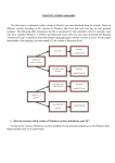
User Replaceable Parts
3
,&#$
-./
")##$)0
12*
&
'($)
* $&"0$&
*
61"&&4% &
#5&
*
)+&
!
"#$%&
61"&&+*3*+
4#5&
Page 3
Model LCD-2R and LCD-2A
Warning Labels
The following warning labels were on your dispenser when it was shipped from the factory. They should remain on
your dispenser in good, readable condition at all times. If one of your labels is missing or damaged, order a replacement label immediately.
Part #62981, Located on lower splash panel on front of dispenser
Part #61321, Located behind the drip pan on the front of the dispenser
Part #61319, Located on the outside on the back of the dispenser
and on the outside on the electrical access panels
Part #61325, Located on the drain hose inside the dispenser
Page 4
Model LCD-2R and LCD-2A
Installation
Water Inlet Connection:
The National Sanitation Foundation requires the following for an NSF approved water hook-up:
1. A quick disconnect water connection or enough coiled tubing so that the machine can be moved for cleaning
underneath.
2. An approved backflow prevention device, such as a double check valve to be installed between the machine and
water supply. A 3/8" male flare adapter is provided on the back of the machine for hook-up to water supply. On
units plumbed to permanent water line, installation of a water filter/softener system is recommended to prevent
lime and scale build up in the machine. On units pumping from remote water container, filtered water is
recommended to prevent lime and scale buildup in the machine.
3. Water pipe connections and fixtures directly connected to potable water supply shall be sized, installed and
maintained in accordance with Federal, State, and Local codes.
Water hook-up:
1. Install the (2) front 4" legs to provide approximately 1/2" clearance with the bottom of the machine.
2. Install drain tray bracket to the front of the machine by sliding the bracket between the front 4" legs and the
bottom of the machine. Tighten the front 4" legs to secure the drain tray bracket.
3. Install the (2) back 4" legs and tighten.
4. Install the plastic drain tray onto the drain tray bracket. (Note: The drain tray is provided with a removable plug to
allow for plumbing the drain tray to a drain.)
5. Install a 3/8 ID flexible water supply hose to the 3/8” male flare fitting on the back of the machine. Ensure the
water supply hose has sufficient length to allow the machine to be moved for cleaning or service. Supplying hot
water to the machine will greatly increase the capacity of the machine. The use of copper tubing is required to
prevent rupture when using a hot water supply. A maximum inlet water temperature of 160°F is recommended.
6. Ensure that the water supply to the machine is within 20 to 100psi. Install a pressure regulator if pressure is too
high.
WARNING:
ELECTRIC SHOCK HAZARD
Only qualified service personnel should perform installation of this appliance.
Improper installation could result in serious injury or death.
WARNING:
ELECTRIC SHOCK HAZARD
Never use the ground conductor as a neutral conductor. Serious injury or
death could occur in the event of a fault condition.
WARNING: ELECTRIC SHOCK HAZARD
Always disconnect power to the machine before servicing or cleaning. Risk of
electric shock is present which can cause serious injury or death.
Page 5
Model LCD-2R and LCD-2A
Installation (cont.)
Electrical Hook-up: Ensure water connection is made to machine before proceeding and water source is
turned ON.
NOTE: Installation must be performed by a qualified electrician and must conform to all local and national codes.
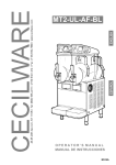
NOTE: Machine is factory configured for field wiring and power cord is not provided. If the machine is intended
to configured to 120 volt operation, a conversion kit 63578 is available for the addition of a proper 120 volt power
cord and a serial tag conversion procedure to match the serial tag to the 120 volt wattage of the heater.
(Refer to Figure A).
"
Page 6
"
The electrical ratings for your dispenser are
located on the serial plate on the outside cabinet.
For configuration of heater to optional wattages,
refer to configuration decal 50524-04 located on
the inside surface of the electrical access panel.
(see Figure B)
1. For cord connected models, plug the power
cord into an appropriate grounded and
dedicated electrical outlet. Go to step 8.
2. For hard-wired models not supplied with an
electrical cord, the dispenser should be
!
connected to a dedicated circuit with a fused
"#$%&'
disconnect switch or a circuit breaker near the
dispenser.
!
"#
$"$%&
'()"%*+*
%,
3. Strain relief knockouts are supplied on the
-.$/0.*"-&12".+*
%0"-2
$*"back of the machine chassis for power entry.
3
0&14
.
$0"-+*5/$.*"• Electrical connections and wiring
Figure A
materials must conform to local codes and/or be in
compliance with the National Electric Code.
• Use only copper conductors
4. Remove the access panel located on
the lower right side of the dispenser.
"
Note: wiring diagram is on
#"$
!
backside of access panel.
"#$
!
!
5. Connect the power supply
conductors, neutral and ground wire
to the appropriate positions on the
!
!
terminal block located on the lower
right side of the dispenser. The
ground lug is separate from the
terminal block.
6. Install the side access panel.
7. Flip power supply to machine “ON”
at the branch supply disconnect.
8. Flip power switch to the “ON”
position and allow the water tank to
fill. The LCD display on the front
door should indicate “FILLING”.
NOTE: Power switch is located at
the right lower rear corner of
%"&' (
machine. The machine will make a
subtle hissing sound while filling.
Figure B
Allow 3-4 minutes for fill time
depending on water pressure.
Model LCD-2R and LCD-2A
Installation (cont.)
9. After the water tank has completed the fill cycle, the display located on the front door of the dispenser should
indicate that the heating element has been activated. Allow 10-60 minutes for the water tank to reach operating
temperature. (Note: Heatup time is dependent on water inlet temperature and input wattage to the machine.)
Bag-in-Box Hook-up
1. Place cups under dispense spouts to catch concentrate and water for priming and dispense operations to follow.
2. Place bag-in-box containers inside the cabinet behind the front door. Connect the quick connect fitting to each
bag-in-box.
3. After connecting the bag-in-box, Activate the appropriate prime switch behind the door in order to prime the
concentrate lines with product. Continue to activate the prime switch until concentrate is dispensed from the
appropriate dispense spout.
4. Repeat steps for other dispense spout.
5. Close front door and ensure that both water and product are dispensed simultaneously into cups when dispense
switches are activated.
How to Dispense a Cup of Coffee
WARNING:
Do not use cups over 6" (15.2 cm) tall with this machine.
Use of cups over this height could result in severed burns and injury.
On models with manual dispense pull handle switches:
1. Place a cup under the selected drink dispense nozzle.
2. Push and hold dispense switch until cup is full and then release switch.
On models with portion control pull handle or push button dispense switches:
1. Place a cup under the selected drink dispense nozzle.
2. Push button for one second, then release to dispense one serving.
Note: Portion may be cancelled by reactivating and release of the switch.
To flush dispense spouts:
1. Place a suitable container under the dispense spout to be flushed.
2. Press the flush button located behind the door and simultaneously activate the dispense switch for the
desired spout to be flushed.
Page 7
Model LCD-2R and LCD-2A
User Programming Instructions
refer to Figure C
Setup Mode
Open the door and insert Setup key into keyswitch
above cooler compartment. Turn key ¼ turn clockwise, the display on front of door will say ‘Setup
Mode, Press Enter’.
The two ‘Prime’ buttons and the Flush button now
become the programming buttons:
Prime 1 = UP, Prime 2 = DOWN, Flush = ENTER
Press the Enter button (flush). The user now has
access to the following options:
Coffee ratio: The user can adjust the strength of
the regular coffee by using the up and down buttons, located to the left of the keyswitch. Once the
required ratio is chosen, press Enter.
Figure C
Decaf Ratio: The user can also set the Decaf ratio, same procedure as
above.
Portion Control: The up and down keys toggle between Enabled and Disabled. When disabled all selections made
by the taps will be continuous until the tap is released. When enabled the taps will give a pre-determined dispense
volume. If portion control is enabled the next screen will ask you to pull the tap of the selection to set – once chosen
you then set the portion size – this can be set one of two ways:
Dispense into vessel: Place vessel to be filled underneath nozzle and press and hold tap – the machine will
dispense water into the vessel and the display will start counting up in 10ths of a second (50 = 5 seconds).
Once the correct level is reached, release the tap. If the level is correct then note the number on the display,
if incorrect then discard the water from the vessel and start again.
Use Up and Down buttons: If by past experience the number for the desired volume is known, then the
volume can be set by pressing and holding the up and down buttons to set the count number.
Once the portion for the selection is set, you can set another by pulling the relevant tap, or press enter to set the
Override portions. You will now be asked to set the Override portion – this is the portion dispensed if the tap is
pressed 10 seconds after pressing the hidden ‘Portion override’ switch that is located underneath the door. Set this
volume in the same manner described above. Once set, press Enter.
Defrost? [No]: If ‘Yes’ is selected then the cooler will defrost any ice build-up. The product is best moved to a
suitable refrigerator during the defrost and the machine door left open to aid with a swift defrost. Cleaning the inside
of the cooler with a warm cloth aids the process too. The machine will automatically start to chill again 15 minutes
after defrost has been activated.
Selections when heating[Disabled]: When disabled the machine will not dispense if the boiler temperature is lower
than the chosen lockout temperature.
Temp Display: There are three options, Fahrenheit, Celsius and Off. Once chosen, press enter.
Now the display will be back to the start menu and will say ‘Setup Mode, Press Enter’. You can either press enter to
scroll back through the options, or you can turn the keyswitch ¼ turn counter clockwise to come out of Setup mode.
Page 8
Model LCD-2R and LCD-2A
“Engineer” Program Settings
TO BE PERFORMED BY A QUALIFIED SERVICE TECHNICIAN ONLY
Engineer Mode
To access engineer mode go into Setup mode, when the screen says ‘Setup Mode, Press Enter’ press the Hot
Water tap – the display will now say ‘Engineer Mode, Press Enter’. The engineer has access to the following
options:
Max Temp [181F]: Sets the maximum temperature of the boiler.
Set Lockout Temp [161F]: Sets the selection lockout temperature.
Power Setting [230v AC]: The input mains voltage has an effect on the heating overrun once the tank has reached
it top temperature, this feature helps combat this. There are two options, 110v AC and 230v AC. If machine is triple
or dual phase then select 230V AC.
Selection Input [Tomlinson Tap]: There are two choices, Tomlinson tap or the touchpads.
Coffee [Enabled]: Disabling coffee will turn off the concentrate pumps during a dispense. Used only when setting
water outlet valve flow rates.
Water [Enabled]: Disabling water will turn off outlet valves during a dispense. Used only when setting concentrate
pump flow rates or calibrating optical concentrate sensors.
Product sensors [Enabled]: If disabled the machine will override the product sensors and will always assume
product is present. Only disable sensors if the sensors are faulty and the machine is waiting for a replacement part.
Product source: Choose between Bag in Box, or Can – this determines which product sensors are used.
Pump 1 speed offset= : This is the calibration setting for the Regular coffee pump. There are 2 settings, one for
continuous flow (<=50:1) and the other for pulsed dispenses (>50:!).
Pump 2 speed offset= : This is the calibration setting for the Decaf coffee pump. There are 2 settings, one for continuous flow (<=50:1) and the other for pulses dispenses (>50:1).
Note: If the actual measured ratio does not match the control set-point ratio, the pump speeds can be offset to calibrate the mix ratio
To offset the pump speeds, enter the “Engineer” mode and adjust the Pump speeds accordingly:
Pump 1 speed offset (Left side dispense head)
Pump 2 speed offset (Right side dispense head)
Increase the offset to increase pump speed (Decreases the actual mix ratio, ie. 30:1 to 25:1)
Decrease the offset to decrease pump speed (Increases the actual mix ratio, ie. 25:1 to 30:1)
Leak Detect [Disabled]: If the machine records 15 refills without a selection then it assumes there is a leak. Disable
when machine is installed on cruise ships etc.
Heat on Selection [Disabled]: Helps with recovery times, every time there is a dispense the heaters are turned on
in anticipation of the refill water. Disable if the machine is wired 230V, or 3 phase or a preheater is used, otherwise
the machine may overheat.
Coffee detect trip point [125]= : This is the calibration setting for the Regular coffee optical sensor.
Decaf detect trip point [125]= : This is the calibration setting for the Decaf coffee optical sensor.
No Prod, no Sel [Enabled]: No product, no selection. Usually enabled – when out of coffee the machine will lock
out the selection.
Page 9
Model LCD-2R and LCD-2A
“Engineer” Program Settings
TO BE PERFORMED BY A QUALIFIED SERVICE TECHNICIAN ONLY
Engineer Mode (cont.)
No prod, Stop Sel [Disabled]: No product, stop Selection. If enabled, when the coffee goes low during a dispense
it will stop, giving a low measure. If disabled it will continue with the dispense even if the coffee goes low, then lock
out once the dispense is finished.
Calibrate Temp: This is the calibration setting for the boiler thermistor.
Calibrate Disp Temp: This is the calibration setting for the dispense thermistor.
Display Heating ? [Enabled]: If enabled the machine will display ‘Heating’ if the dispense thermistor is reading
below the lockout temperature. If disabled the temperature display goes blank when locked out, unless it is heating
from initial turn on.
Water level Trip [50]: This adjusts the sensitivity of the water level sensor. The figure may need to be adjusted
higher if the machine is being supplied by water with very little impurities (bottled water in exhibitions, for example).
View level Reading [Disabled]: This is enabled when setting the water level trip point – always disable once trip
point is set.
Temp display source [Disp]: Used when calibrating the boiler thermistors, options are GM thermistor (boiler), dispense thermistor, or both together. Always select Dispense thermistor once calibrated.
Once you have scrolled through all these options, the machine will revert back to Setup mode.
Machine Fault Codes
1: Overflow
The Inlet valves may be blocked open. The overflow float may have failed, connections from the overflow float to the
PCB may have failed.
2: Water sensor fail
The water sensor thinks the boiler is empty but the overflow float is up. Connections from the sensor to the PCB
may have failed. The sensor loom may be disconnected from the Control PCB.
3: Thermostat overheat
The limit thermostat has tripped. This currently isn’t being monitored by the control logic.
4: Lack of Water - Insufficient water during normal operation.
If the inlet valves have been on for over a minute since the last call for water then it assumes insufficient water.
There may not be sufficient water pressure to flow past the valves. The water supply may have been turned off.
There may be a blockage in the inlet pipe either before or after the inlet valves. Connections from the inlet valves to
the PCB may have failed. The inlet valve loom may be disconnected from the Control PCB. Inlet valve may be
blocked or failed closed.
5: Lack of water #1 - Insufficient water from initial fill.
If inlet valves have been on for 8 minutes from the time the machine is turned on then it assumes insufficient water
to fill the tank. Possible causes have been outlined above.
Page 10
Model LCD-2R and LCD-2A
“Engineer” Program Settings
TO BE PERFORMED BY A QUALIFIED SERVICE TECHNICIAN ONLY
Machine Fault Codes (cont.)
6: Water overheat
The thermistor has detected the water is too hot. The boiler element contactor may have failed short circuit. The
machine may be running high Wattage Power with a preheater.
7: Leak
If the machine refills 15 times without a dispense the machine assumes a leak. A water outlet valve may be leaking.
8: Inlet valve leak
Not available with single inlet valve machines
9: Tank thermistor fail
The thermistor has failed open circuit, or connections from the thermistor to the PCB may have failed.
10: Reset System
The watchdog timer on the control chip has timed out, the machine needs a reset. (Turn machine off, wait 5 seconds, turn back on).
Programming Guide for Calibration of Mix Ratio (refer to Figure D)
1. The water dump valves are factory set to
60 ml/sec (2 fl-ounces per second). If
adjustment is required, disconnect power to
the machine and remove the left side
access plate to gain access to the dump
valves.
2. Using an appropriate hex key, turn the
adjustment screw on each dump valve
clockwise to fully close the adjustor (Do not
force the adjustment as permanent damage
can occur to the valve)
3. Turn each dump valve adjustor counter
clockwise as indicated below to achieve
(2) fl-ounce per second.
Top valve =
Left dispense head= 5.5 turns out CCW
Figure D
Middle valve=
Middle dispense head= 4.5 turns out CCW
Bottom valve =
Right dispense head= 4.0 turns out CCW
4. Reassemble machine and power ON.
Page 11
Model LCD-2R and LCD-2A
“Engineer” Program Settings
TO BE PERFORMED BY A QUALIFIED SERVICE TECHNICIAN ONLY
Programming Guide for Calibration of Mix Ratio (cont.)
To check water flow rate and calibrate the actual mix ratio adjustment to match the programming mix ratio:
IMPORTANT NOTE REGARDING
PORTION OVERRIDE BUTTON:
The default time setting for the override portion is 100 which
equates to 10.0 seconds. The override dispense volume
should be set to 100 (= 10.0 seconds) for calibration purposes. Follow the programming guide to determine and change
the setting to 100 for calibration purposes.
WARNING:
A dispense time greater than 10 seconds will
require a graduated beaker larger than 1000ml in
order to safely catch the dispensed “HOT” water.
1. Disable the concentrate pumps by entering the “Engineer”
setup mode as indicated above. This will allow
determination of the exact water delivery for a
Override portion button: Press and release; then
10 second dispense.
activate desired dispense switch within 5 seconds
for a 10 second dispense cycle.
2. Using a 1000ml beaker (ensure override time setting is
set to 100 for a 10 second dispense), push and release the hidden
override portion button located on the bottom left side of the door as shown above. Within 5 seconds, place the
1000ml beaker under the dispense spout and activate the desired dispense switch and capture the dispensed
water into the beaker.
NOTE: Activating the dispense switch during the portion dispense cycle will cancel the portion.
Record the water volume and repeat at least 2 times to achieve an average dispense volume.
3. Re-enter the “Engineer” mode programming and re-enable the concentrate pumps, then disable the water delivery
to allow only concentrate to flow from the dispense spouts.
4. Using a 50 ml beaker with an opening sufficient to capture the flow of concentrate from the dispense spout, push
and release the hidden override portion button located on the bottom left side of the door as shown above. Within
5 seconds, place the 50 ml beaker under the dispense spout and activate the desired dispense switch and capture
the dispensed concentrate into the beaker. Record the concentrate volume and repeat at least 2 times to achieve
an average dispense volume.
Page 12
Model LCD-2R and LCD-2A
“Engineer” Program Settings
TO BE PERFORMED BY A QUALIFIED SERVICE TECHNICIAN ONLY
Programming Guide for Calibration of Mix Ratio (cont.)
Worksheet
Average water volume / Average concentrate volume = mix ratio
Example: 600 ml water / 20 ml concentrate = 30:1 ratio
Dispensed Water
1. _____________ ml
2. _____________ ml
3. _____________ ml
Average: _____________ ml
Water Flow Rate = Average ml / Override Portion Time = ml/second
Water Flow Rate = _____________ ml / _____________ seconds = _____________ ml/second
Dispensed Concentrate
1. _____________ ml
2. _____________ ml
3. _____________ ml
Average: _____________ ml
Mix Ratio Calculation
Average Dispensed Water (ml) / Average Dispensed Concentrate (ml) = MIX RATIO
_____________________ (ml) / ___________________ (ml) = _____________ MIX RATIO
Page 13
Model LCD-2R and LCD-2A
Weekly Cleaning Instructions
refer to Figure E
NOTE: Some bag-in-box connectors require some disassembly for cleaning and sanitizing
NOTE: Some bag-in-box connectors requires some extra steps for cleaning and sanitizing.
1. Remove fitting cap (a) from bag-in-box quick disconnect fitting if applicable.
2. Then, if equipped with an internal check valve follow the following steps:
3. For QCD (Liqui-Box) fitting remove fitting cap (a) then remove the internal check valve parts by using the edge of
a coin or a screw driver as shown. This will allow for the free flow of sanitizing solution.
4. For Scholle (T) fitting, first remove the fitting cap (a) then cut out an outlet spout from a used bag as shown. Then
screw it onto the Scholle (T) fitting. This will allow for the free flow of sanitizing solution.
5. For Scholle (L) fitting, first cut out an outlet spout from a used bag as shown. Then screw it onto the Scholle (T)
fitting. This will allow for the free flow of sanitizing solution.
6. For Scholle (Quick-Clic) fitting, by design, no steps are needed to allow for the free flow of sanitizing solution.
(a)
OUTLET FROM
USED BAG
COIN
QCD (LIQUI-BOX)
SCHOLLE (T)
SCHOLLE (L)
SCHOLLE (QUICK-CLIC)
Figure E
7. Insert the bag-in-box quick disconnect fitting into a one gallon (3.8L) basin of very warm (150°F/65.56°C) water
without soap.
8. Activate the corresponding prime switch until clear soapy water is dispensed from the spout.
9. Flush soapy water by repeating steps 3 and 4 using one gallon (3.8L) of very warm (150°F/65.56°C) water
without soap.
10. Prepare one gallon (3.8L) of food grade sanitizing solution in a container per manufacturer’s recommendations
and repeat step 4 until sanitizing solution is dispensed from the spout. Let sanitizing solution work for 5 minutes,
then flush the concentrate line by activating the prime switch until the sanitizing solution dispenses clear.
NOTE: Recommended sanitizing solution is KAY-5 Sanitizer/Cleaner; mix one ounce (28g) packet of sanitizer
powder + 2.5 gallons (9.5L) of warm (approximately 120°F/48.89°C) water to achieve a solution of 100ppm of
available chlorine.
11. Remove the bag-in-box connector from the sanitizing solution basin and purge the concentrate line by pushing
and holding the dispense switch until the concentrate tube runs dry.
12. Flush the concentrate line with fresh water by submerging the bag-in-box connector in a one gallon (3.8L)
container of fresh tap water and activating the corresponding dispense switch for one minute.
13. Re-assemble the bag-in-box connector, then reconnect the bag-in-box connector to a bag-in-box of concentrate.
14. Prime the concentrate line by activating the prime switch until concentrate drips from the spout.
15. Activate dispense and discard (2) 6 ounce (168g) drinks from dispense nozzle.
16. Repeat all steps for other dispense heads.
Page 14
Model LCD-2R and LCD-2A
Service and Cleaning
Draining the Tank
Always empty the tank before shipping.
WARNING:
Draining of tank should be performed by a qualified service technician.
The tank contains 4 gallons (15.1 litre) of very hot water. May cause severe burns.
1.
2.
3.
4.
Prepare a minimum 5 gallon (17.5 litre) heat resistant container to drain the tank water into.
Unplug the machine.
Remove the drain tray and front access panel.
Locate the silicone drain hose. Put the end of the drain hose into the bucket. Secure the end of the drain hose (i.e.
with tape) into the bucket.
5. Remove the hose clamp and plug.
6. Allow the tank to drain completely.
WARNING: Do not attempt to stop the flow of water once it begins to drain.
7. Once the tank is empty, securely replace the plug and clamp on the end of the hose. Reposition the drain
hose inside the hose clip on the left side wall.
8. Reassemble the front access panel and drain tray.
Purging Machine of all Water for Shipment in Cold Areas
WARNING:
This procedure should be performed by a qualified service technician.
The unit can be purged of water as follows:
1. Turn the power switch to the "OFF" position.
2. Drain the water tank (refer to instructions above.) Do not replace the drain hose plug and clamp until
further instructed.
3. Turn the power switch to the "ON" position. The display should indicate “lack of water” within 12 seconds. The 12
second delay signals that the heating element has been disabled due to the lack of water in the tank after it is
drained.
Important: If the display does not indicate “lack of water” within 12 seconds, turn the power OFF to
avoid burning out the heating element.
4. Listen for the inlet valve to energize. Ensure the tank drain tube is directed towards a container to catch residual
water before air is supplied to purge the line. To purge the inlet valve and water inlet tube, apply 10-20 psi compressed air to the inlet valve connection for 10 to 20 seconds while the inlet valve is energized.
Note: Do not energize the inlet valve for more than 5 minutes at a time. Otherwise, the watchdog timer will disable
the inlet valve. If this occurs, reset the machine by flipping the power switch off then on.
5. Reassemble the machine.
Page 15
Model LCD-2R and LCD-2A
Troubleshooting Guide
A troubleshooting guide is provided to suggest probable causes and remedies for the most likely problem
encountered. If the problem remains after exhausting the troubleshooting steps, contact GrindmasterCecilware Technical Service Department (800-695-4500, 8am-6pm, M-F).
• Only qualified service personnel should perform inspection, testing, and repair of electrical equipment
• Intermittent operation of electronic circuit boards is unlikely. Board failure will normally be permanent. If an
intermittent condition is encountered, the cause will likely be a switch contact or a loose wire connection at a
terminal or crimp.
• The use of two wrenches is recommended whenever plumbing fittings are tightened or loosened. This will help
avoid twists and kinks in the tubing.
• Make certain that all plumbing connections are sealed and all electrical connections are tight and isolated.
• This dispenser is heated at all times. Keep away from combustibles.
WARNING:
• Exercise extreme caution when servicing electrical equipment.
• Disconnect power from the power source when servicing, except when electrical tests
are specified. The illuminated blue LCD on the door indicates that the unit is powered
ON. Of the blue LCD display is OFF, power is still supplied to some of the internal wiring
of the machine.
• Follow recommended service procedures.
• Replace all protective shields or safety notices.
• Replace any worn or missing safety notices.
Control Board Diagnostic LEDs
The control board incorporates (4) LED indicators for
assessing the status of the noteed inputs and outputs.
Page 16
Model LCD-2R and LCD-2A
Troubleshooting Guide (cont.)
WARNING:
Risk of electrical shock. Disconnect power before removal of any machine access panels.
Problem/Cause
Remedy
MACHINE DOES NOT POWER UP
Machine is unplugged
Ensure machine is plugged into power supply
Power switch in OFF position
Flip power switch to “ON” position (located at lower right corner
of back of machine); Blue LCD on door should be illuminated
when ON.
Branch circuit breaker has tripped
Reset circuit breaker at service supply panel
Power supply external fuse is blown
Check and replace fuse if necessary (located behind lower right
side chassis access panel).
NO HOT WATER FROM DISPENSE HEAD
Faulty water tank heater
Check heating element resistance; replace if necessary.
Water Fill circuit “watch dog timer” has tripped
Turn power switch “OFF” for 5 seconds, then “ON” (located at
lower right corner of back of machine)
Water supply to machine is turned OFF
Check for flashing diagnostic lights on control board
See diagram of control for explanation of lights.
Level probe sensitivity is too high
Water is disabled in programming
Check “Engineer” programming to ensure water is enabled.
NO CONCENTRATE IS DISPENSED
Bag-in-Box is empty or disconnected
Ensure Bag-in-Box is not empty; replace with new Bag-in-Box if
empty.
Bag-in-Box connector is pointing up. (This position can create a Position Bag-in-Box connector pointing down to provide a
partial vacuum in the concentrate tube which may prevent
positive pressure in the concentrate tube.
product from being pumped to the dispense spout.)
Concentrate pickup tube is kinked
Inspect tubing routing and ensure concentrate tubing is not
kinked.
Concentrate pump tubing, product out switch, or Bag-in-Box
fitting is clogged.
Periodically clean and sanitize tubing per the cleaning and
sanitizing procedure in the instruction manual.
“Coffee” is disabled in programming.
Check “Engineer” programming to ensure “Coffee” is enabled.
WATER TANK OVERFLOWS THROUGH TANK VENT AT BOTTOM OF MACHINE
Weeping fill valve seat
Call for service.
WATER TANK OVERFLOWS THROUGH TANK VENT AT BOTTOM OF MACHINE
Note: A secondary float switch located in the water tank is intended to indicate an overflow condition at the LCD display.
Weeping water inlet valve
Page 17
Check water inlet valve; replace if necessary. (Note: a slow
overflow indicated this condition.)
Model LCD-2R and LCD-2A
Troubleshooting Guide (cont.)
Problem/Cause
Remedy
LCD DISPLAY INDICATES “OVERFLOW”
NOTE: Water must be drained from the tank below the float switch after the fault condition is diagnosed.
Water level probe sensitivity is set too low
Increase sensitivity of water fill circuit (see programming notes:
Water Level Trip)
Faulty or corroded level probe
Remove level probe and grommet. Remove any scale or mineral buildup and reassemble.
Faulty level control circuit wiring
Ensure both probe and probe ground connections are securely
fastened to water tank top. Check wiring for defects.
Inlet water pressure too high
Ensure water pressure is below 100 psi
Weeping water inlet valve
Check water inlet valve; replace if necessary (Note: a slow
overflow indicates this condition)
WATER TANK BOILS
Temperature setting too high for elevation of installation
Heater contactor stuck in closed position
Defective thermistor
Adjust temperature down, refer to temperature adjustment in
Operators Manual.
Check contactor for welded contacts; replace if necessary
Check for flashing diagnostic lights on control board and refer
to explanation of diagnostic LEDs
WATER CONTINUES TO DRIP FROM DISPENSE SPOUT
Weeping dispense valve
Replace dump valve
CONCENTRATE CONTINUES TO DRIP FROM DISPENSE SPOUT
Peristaltic pump tube is worn out
Call for service.
Incorrect tubing installed
Confirm that tubing is OEM part; replace if necessary
DRINK IS TOO WEAK OR STRONG
Mix ratio needs adjustment
Refer to “Setup” section of programming guide to alter Coffee
and Decaf ratios.
Blocked pump and delivery tubing (too weak)
Follow cleaning instructions to prevent restrictions inside pump
tubing
Pump tubing is worn out (too weak)
Replace tubing on an as-needed basis depending on usage
DRINK IS TOO HOT OR COLD
Refer to “Setup” section of programming guide to alter water tank temperature.
Heavy usage
Consider providing hot water to the supply inlet to maximize
recovery
Consider having the machine converted to 240V operation for
maximum recovery time
OFF TASTE OF COFFEE
Machine needs cleaning
Poor water quality to include high chlorine level, heavy mineral
concentration, or stale water.
Follow cleaning instructions to ensure concentrate delivery
tubing is clean
Install a taste and odor filter to the water inlet of the machine.
Water tank requires descaling.
Drain water from tank, remove tank, remove tank and de-scale,
thoroughly rinse tank before re-installing. Flush tank with fresh
water several times before replacing in service.
Out of date coffee concentrate
Check date stamp on product container
Page 18
Model LCD-2R and LCD-2A
29(55,'(
6:,7&+
&2))(( :$7(5 '(&$)
35,0('2:1
)/86+(17(5
:+7
*5<
'LVSHQVH
GLVDEOH
VZLWFK
.(<3$'237,21
&2))((
3(/7,(5
&22/,1*
(/(0(17
)$1
.(<3$'237,21
'(&$)
5('
'(&$)
237,&$/
6(1625
237,21
&2))((
9$&880
6(1625
&2))((
237,&$/
6(1625
237,21
&21752/3&%
*5<
*5<
35,0(83
5('
9'&
3RZHU
,QSXW
/&'',63/$<
2UDQJH
<HOORZ
9LROHW
*UH\
3LQN
7DQ
6(783
.(<6:,7&+
5('
%/.
)$1
*5<
5('
:+7
:+7
%/.
%/.
%/.
%/.
<(/
<(/
7$1
3,1.
*5(<
9,2/(7
<(//2:
25$1*(
%/8(
%52:1
*5((1
5('
:+,7(
%/$&.
%/8(
%52:1
*5((1
5('
:+,7(
%/$&.
9,2
31.
*51
:+7
*5<
%/.
*51
:+7
5('
%OXH
%ODFN
:KLWH
5HG
*UHHQ
%URZQ
7$1
3,1.
*5(<
9,2/(7
<(//2:
25$1*(
%/.
*51
:+7
5('
'(&$)
9$&880
6(1625
&22/(5
7+(50,6725
25*
31.
%/8
<(/
%/.
%/.
5('
31.
5('
%/8
5('
9,2
&2))((
3803
',63(16(
7+(50,6725
7$1.
7+(50,6725
:$7(5
/(9(/
6(1625
(/(0(17
5(/$<
,1/(7
9$/9(
29(5)/2:
)/2$7
287/(7
9$/9(6
31.
31.
%/.
25*
%/.
%51
5('
5('
9,2
9,2
5('
%51
5('
:+7
%/8
*5<
Page 19
%/.
5('
'(&$)
287/(7
9$/9(
:$7(5
287/(7
9$/9(
&2))((
287/(7
9$/9(
+,/,0,7
7
67$7
,1/(7
9$/9(
29(5)/2:
)/2$7
6:,7&+
'(&$)
3803
:+7
&KDQJHGFRORUFRGLQJRI
WRXFKSDGKDUQHVVWRPDWFK 7-3
5HY&RIKDUQHVV
0RGLILHGWRLPSURYH
OHJLELOLW\
'$7(
7-3
:+7
/
/
&2,/
%/.
/
/
:+7
%/.
%/.
)86(
%/.
&RQQHFWWR/DVVKRZQIRUYROWZDWW
PLQLPXP$:*FRUGDJHRU
&RQQHFW/WR1HXWUDOIRUYROWZDWW
PLQLPXP$:*FRUGDJH
%/.
&2,/
YGF
32:(5
6833/<
5(*8/$7,1*
&217$&725
7
7
%/.
(/(0(17
5(/$<
9
9
9
9
*
/
1
%/.
5('
5('
*5<
*5<
*5((1<
%/.
:+7
/,0,7
&217$&725
7
7
%/.
%/.
,1/(7
9$/9(
5(/$<
+($7,1*
(/(0(17
%/.
%/.
%/.
%/.
%\
&KDQJHG/&'GLVSOD\
ZLULQJFRORUFRGHWRPDWFK 7-3
&DURO&DEOH&$
'(6&5,37,21
1
/
/
/
:,5,1*
7(50,1$/
%/2&.
:+7
:+7
%/.
(&1
%/.
67$1'%<
6:,7&+
':*
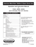
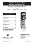
YDF/&'$5:,5,1*6&+(0$7,&
'
&
%
5(9
Wiring Diagram
Model LCD-2R and LCD-2A
Grindmaster® Coffee Grinders and Brewers • PrecisionBrew™ Brewing Systems • Espressimo® Espresso Machines
Crathco® Hot Beverage Dispensers • Crathco® Cold and Frozen Beverage Dispensers • AMW Coffee and Tea Systems
Tel (502) 425-4776 • Fax (502) 425-4664 • 1-800-695-4500 (USA & Canada only)
P.O. Box 35020 • Louisville, KY 40232 • USA
www.grindmaster.com • email: [email protected]
© Grindmaster Corporation, 2009
PRINTED IN USA
0910 Form # AM-328-04
Part # 63543