1
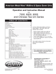
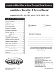
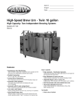
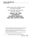
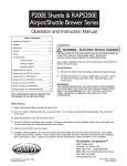
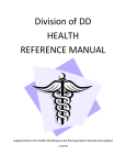
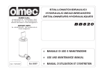
American Metal Ware®
Installation, Operation & Service Manual
For
High Speed Brewing Urn (Top Line)
TABLE OF CONTENTS
General Description.................................3
Roughing-In Drawing...............................4
Installation...............................................5
Spray-Over Time/Volume/Rate................6
How To Brew............................................7
Thermostat/Adjustments/Timer...............8
Care and Cleaning..................................9
Explanation of Agitation System............10
Operation Malfunction and Service........11
Dual Lever Control................................12
Troubleshooting Level Control...............14
Service/Troubleshooting Agitation.........18
Installation/Service for Solenoid Valve...18
Sprayover Pump Breakdown.................20
Illustrated Parts Breakdown...................21
List of Illustrated Parts...........................22
Parts List...............................................23
Wiring Diagram - Controls.....................24
Heater Wiring Diagram - 208V/240V......25
Heater Wiring Diagram - 480V..............26
Model 87710
Dual Wall Insulated
X Electric
Steam
Special Features
After completing installation and set-up, the
equipment owner should keep this manual for
future reference.
Grindmaster Corporation™
4003 Collins Lane
Louisville, Kentucky 40245 USA
(502) 425-4776
(800) 695-4500 (USA and Canada only)
(800) 568-5715 (technical service only)
FAX: (502) 425-4664
www.grindmaster.com
© Grindmaster Corporation™, 1995
PRINTED IN USA
1104 Form # AM-307-02
General Description
This urn is an automatic, push button operated, volume brewing unit. It consists of a nonpressure vented water compartment of large capacity into which two stainless steel coffee
liners are inserted. Also installed within this water compartment are electric immersion
heaters thermostatically controlled through a contactor relay, to keep the water always at
the desired temperature. Measurement of water quantity sprayed over coffee is by push
button start, electric reset timer, timing a constant water flow rate to the spray nozzle.
Hot water from the water compartment is pumped to the spray nozzle, controlled by the
reset timer. Automatic refill maintains water level in water compartment. Control system
components are enclosed in stainless steel housings on both ends of the urn for the 87710
urn.
Air agitation of coffee mixes the brew with compressed air automatically at the end of the
brew cycle or, if desired, manually at any time with a push button.
American Metal Ware 87710E Coffee Urn
Page 3
Page 4
American Metal Ware 87710E Coffee Urn
Installation
1.
IMPORTANT TO ALLOW 6” CLEAR SPACE FOR ACCESS TO CONTROL BOX.
Urn should be level, both front to back and left to right.
2.
CONNECT WATER LINE. 3/8” NPT water inlet located at left end and provide shutoff
valve and union in supply line near urn. 140OF. hot water must be used, 30PSI minimum - 70PSI maximum. We strongly recommend the use of copper or aluminum tubing to provide flexibility and avoid strain on the urn. 3/8” O.D. minimum tubing is recommended.
Model No.
Actual Coffee Capacity Each Liner
Water Compartment Capacity
Brew Capacity, Gals. per Hour
Electric Supply Voltage
1 Phase Heater Size
1 Phase Amperes
3 Phase Heater Size
3 Phase Amperes
3.
87710
10 Gal.
24 Gal.
80
240V/208V
15KW / 15KW
63 / 72
15KW / 15KW
36 / 42
CONNECT URN TO ELECTRIC POWER. Check to be sure that the nameplate marking of voltage, phase and the number of wires matches supply lines. Remove cover on
control housing. The terminal block for the line connections is located in the housing
on the left end. See drawing, as required. It is recommended that a fused disconnect
switch be installed near urn. The urn body must be grounded either through metallic
conduit or else by means of ground wire. An experienced electrician should be responsible for the installation of the urn, and its associated supply line. NOTE: Neutral wire
required on all single phase and on 208 volt 3 phase power supplies to operate 120 volt
AC control circuit.
On single phase, 2 wire service (no neutral) or 3 phase 3 wire service (no neutral) 120
volt AC power to operate control circuit must be supplied as circuit. Do not replace
cover until completing installation start-up.
4.
FILL WATER COMPARTMENT. Turn on water supply and electric service to urn.
Water compartment should fill to stop-full level in approximately 10 minutes.
Turn thermostat knob to BREW position. Pilot light over knob should light showing
heater power on. Water compartment should reach operating temperature approximately 45 minutes later. When the pointer on thermometer approaches the “W” in the
blue BREW zone, urn is ready for automatic operation.
American Metal Ware 87710E Coffee Urn
Page 5
Spray-Over Time - Volume - Rate
Timer and spray-over rate are factory set as per information below. If other volumes of
water or a faster or slower spray-over rate is desired, see following instructions:
Timer Adjustment
Turn adjustment knob clockwise to decrease time, counterclockwise to increase time.
Operation Start-Up Checks/Brew Cycle Adjustments
1. Turn thermostat dial to BREW position. Pilot light at top of thermostat bezel should light
up when thermometer pointer is at “W” in BREW zone, this pilot light should go out.
Water in urn tank is now at brew temperature. NOW and ONLY at initial start-up, we
advise checking time of flow of hot water to spray nozzle.
2. CHECKING SPRAYOVER VOLUME AND RATE (REPEAT FOR EACH SPRAYARM)
Remove cover from brew basket over one liner. Position spray nozzle over this brew
basket. Liner should be empty and faucet shut off. Push in timer start button and brew
pilot should light up. Hot water should start to spray into brew basket. Allow to spray until
brew pilot light goes out and sprayover stops.
Measure amount sprayed over by drawing off into a calibrated one gallon measure. If
amount is more or less than desired, reset timer. Longer time, more sprayover, shorter
time - less sprayover. Each 1/4 minute increase or decrease adds or subtracts about 1/4
gallon to sprayover total. Note that setting of sprayover bypass valve (on sprayarm)
affects amount of sprayover.
Further adjustment of sprayover volume can be made using the internal bypass valve
located in the side pump housing. Screwdriver adjustment is under the hole plug closest
to the urn body. Open the valve for less sprayover, close for more. Valve is wide open
when screwdriver slot is horizontal. It is closed when slot is vertical; i.e., pointing towards
sprayarm for maximum sprayover. The purpose of the internal bypass valve is to direct
excess discharge from the sprayover pump back into the urn water compartment.
Factory setting is 10 gallons sprayover water in 10 minutes (1 gallon/60 seconds) and
sprayover bypass valve wide open. Bypass volume is about 30% of the total sprayover,
or 3 gallons.
Before actual use of urn, it should be thoroughly cleaned and washed. It is also
recommended that a batch of coffee be brewed in each liner based on a final brewing
cycle timer setting and actual muslin bag or filter be used. We recommend that these first
batches be thrown out and not used. Strength of brew may be checked by hydrometer
or evaporation tests but flavor test might be poor on the first batch.
Page 6
American Metal Ware 87710E Coffee Urn
How To Brew In An Automatic Urn
1. Place filter in brew basket with designated amount of ground coffee (automatic urns are
designed to use 1, 2, 3 or 4 lbs. of coffee). Make certain you have a level bed of coffee.
Consult your coffee supplier for exact brewing specifications. (C.B.C. recommendation
is 1 lb. of coffee to each 2 1/2 gallons water).
2. Replace cover and move spray head over center of coffee grounds.
3. Check thermometer to make certain urn is at brewing temperature. Press timer button.
4. When brew cycle is completed (brew light shuts off), remove brew basket and dispose of
spent grounds.
5. Mixing of finished brew is accomplished automatically at the end of the brew cycle if the
urn has an air agitation option. Additional mixing can be performed at later time by
pressing manual air agitation push button.
Where urn is not equipped with air agitation, draw one gallon for each three gallons of
finished brew from coffee faucet, and pour over top into coffee liner.
The coffee is ready to serve.
6. Hold coffee at 185O - 190O F. or HOLD setting on thermostat knob. Brewed coffee can be
held at this temperature for up to one hour with minimal deterioration of flavor and body.
Explanation Of Brewing Cycle
1. When timer button is pushed, the timer is activated.
2. The timer completes the circuit to the sprayover pump which delivers hot water through
the spray arm to the spray nozzle.
3. The hot water from the spray nozzle is sprayed over the coffee grounds. The finished
brew collects in the coffee liner.
4. As the pump delivers hot water from the water compartment through spray nozzle into
brew basket, the water level in the water compartment lowers.
5. Drop in water level in water compartment below sensing probes activates liquid level
control which opens the refill solenoid valve, refilling the water compartment with cold
water.
6. The entry of the cold water activates the thermostat, which allows power to go to the
heating element to maintain the brewing temperature
NOTE: Some urns may be equipped with an optional adjustable bypass valve on the spray
arm. Adjustment of this valve will allow some spray water to bypass the brewing basket for
additional control of the water/coffee brewing formula and the extraction percentage from
the coffee.
American Metal Ware 87710E Coffee Urn
Page 7
Thermostat
The thermostat is factory set so that the knob on the BREW setting holds the urn at
brewing temperature toward the HI end of brew zone on the thermometer dial. Then, if
turned back to HOLD position, the thermostat should cycle on and off and hold at the LO
end of the BREW zone on the thermometer.
Thermostat Adjustment
1. If the water temperature is below the HI end of the BREW zone on the thermometer dial
with the knob on BREW setting, remove the knob by pulling it straight outward. Using a
small screwdriver, insert in the hole in the center of the shaft, turn slotted screw counterclockwise until the red pilot light goes on. Check to see that water in the urn holds at the
HI end of the BREW zone on the thermometer and does not boil.
2. If the water boils with the thermostat knob set at the BREW position, remove the knob by
pulling it straight outward. Using a small screwdriver, insert into the hole in the center of
the shaft, turn slotted screw clockwise until the red pilot light goes out. Hold shaft so it
does not turn while adjusting screw. Add cold water and check that the heat comes back
on (pilot light glows), and that the thermostat cycles at temperature at HI end of the
BREW zone on thermometer dial.
If the thermostat will not cycle, replace the entire control.
Push Button Timer For Spray Over Control
The function of the timer is to start the pump and run it for a preset period of time and upon
lapse of this time, to stop the pump, thereby completing the spray over cycle.
This urn is equipped with an electric reset timer. Pushing in the START button will start the
flow of water. The timer will complete the time cycle for which it has been programmed and
on completion, the flow will be stopped and the timer will reset itself, ready for the next
brewing cycle.
If electric power is cut off anywhere in the service coming to the urn during the timer
operating cycle, the timer will reset. When the power is restored, the timer must be
restarted by pushing the START button.
Spray Rinse Of Liner
To rinse the liner after brewing coffee, swing the spray arm over the desired liner and push
START button. Allow hot water to spray from the spray arm for approximately 30 to 60
seconds and then push STOP button and drain the liner.
Page 8
American Metal Ware 87710E Coffee Urn
Care and Cleaning of Coffee Urn
1. Always rinse the urn immediately after each use.
2. Add small quantity of hot water, brush sides and rinse with hot water until it runs clean.
Urn is now ready for next batch.
3. At end of each day clean and brush urn several times, then rinse thoroughly with hot
water.
4. Remove clean-out cap at the end of the coffee faucet (or take apart faucets which have
no caps) and scrub pipe leading to center of urn. Clean urn gauge glass with brush and
urn cleaner. Rinse!
5. Scrub the faucet, then rinse it thoroughly with hot water.
6. Place a gallon or more of fresh water in the urn until next use.
7. Remove cover and clean. Replace cover, and leave partly open.
8. ALWAYS REMEMBER TO EMPTY, AND RINSE THE URN WITH HOT WATER BEFORE
USING AGAIN.
NOTE: On automatic urns, use brew start and stop switches, or the rinse switch, to spray
scalding hot water into liner for cleaning and rinsing. On pourover urns, draw hot water
directly from urn. Make sure urn water tank is kept near full, and heat is on.
Semi-Weekly Cleaning Procedure
1. Be sure that the outer jacket is full of water.
2. Turn on the heat and fill the urn liner 3/4 full of water; use only urn cleaning compounds,
following manufacturer’s directions; mix thoroughly and let stand about 30 minutes.
3. Clean the gauge glass, faucet pipe, plugs, etc. using long thin brush. Use urn cleaning
solution for scrubbing. Take faucet valve apart and clean thoroughly. Clean all tubes
well.
4. Scrub inside of urn and inside of cover with long handled brush. Be sure to clean the
“lug nut” in the base of urn liner.
5. Rinse the inside of the urn three or four times with hot water - scrubbing each time. Also
rinse parts well. Repeat until all traces of foreign odor and cleaning solution are
removed.
6. Leave a gallon or more of fresh water in the urn with the cover partly open until the next
use. If cold water is used, allow urn to cool to prevent cracking liner.
7. The urn baskets may be cleaned by immersing them in urn cleaner solution and scrubbing with a stiff brush. Rinse thoroughly and let dry. Sprayheads should be checked to
see that all holes are open. If any are clogged, remove sprayhead and use stiff wire to
open.
8. Don’t use soap, scouring powders, or abrasives to clean coffee brewing equipment.
WARNING: Cleaner used can affect taste of coffee if not thoroughly flushed out as covered above.
NOTE: Coffee system cleaners that have been used successfully:
DIP-IT manufactured by Economics Laboratories, Inc., 4 Corporate Park Drive, White Plains, NY 10604
OXYLITE manufactured by Avril, Inc., Syndet Division, 601 N. Third Street, Reading, PA 19601
TEMP-KLEEN manufactured by Caddy Corp. of America, Pitman, NJ 08071
American Metal Ware 87710E Coffee Urn
Page 9
Solid State Coffee Agitation System
Coffee agitation is accomplished with low pressure air, bubbling up through the coffee in
liner. Air enters at the top coffee gauge elbow fittings and forces coffee down out of sight
in gauge glasses during the agitation period. Air continues through into the liner connection
elbow, and bubbles up from this center fitting. The rich, heavy portion of brew is carried up
to the top and thoroughly mixed with weaker top level coffee.
Automatic Program - End of Brew and Delayed Types
At the end of the spray cycle, the air pump turns itself on for about 30 seconds automatically. This automatic agitation program is either built into the solid state spray cycle (brew)
timer or is provided by a separate solid state agitation relay on equipment with mechanical
timers. Urns with delayed air agitation (Option 43D) have a two minute delay after the end
of the brew cycle before the 30 second agitation cycle starts for improved mixing. This
delayed program is provided by a separate delay solid state relay. Whenever power to the
urn has been off, such as upon installation, the automatic agitation program will begin as
soon as the power is turned on. Otherwise, it operates only after the end of spray.
Manual Agitation
At any desired time, holding in the “manual agitation” black push button switch will blend
stored coffee.
Note: The plug in the cleanout cap at the top of the coffee gauges must be pushed in
completely to avoid air leaks. Gauge glasses are cleaned with a gauge brush by first lifting
out the top cap. (A slight twist will release a tightly sealed cap). Be sure to replace the cap
properly so that the agitation system can operate.
WARNING: Overfilling coffee liners may damage air pumps. Never overfill liners at any
time.
Page 10
American Metal Ware 87710E Coffee Urn
Operation Malfunction and Service
Problem - Thermostat dial turned to brew and water in tank remains cold.
Possible Cause
Service Checks and Cures
1. No power at urn.
Check main switch. Check main fuses.
(Three on 3 phase power, two on single
phase power). Check that pilot light at top
of thermostat bezel is ON.
2. Power at urn, but no power
at heater terminals.
Check urn control circuit breaker or fuse,
reset or replace if needed. Check that water
level is at STOP mark on gauge. Check that
power contractor has power at coil, and
clicks open and closed at thermostat dial is
turned off and to BREW position. Check
control transformer, if supplied. It may be
burned out. Lastly, check for voltage at
heater terminals. If voltage at heater is
O.K., check for broken or loose wire. Water
must be showing in center gauge glass 2” if
Opt. 39 equipped.
3. Power at heater terminals,
but no heat.
Check heater for an open circuit with
ohmmeter or continuity tester. If necessary,
replace heater. (It is necessary to remove
coffee liner to replace electric heater).
PROBLEM: Water boils continuously with thermostat dial on position
“BREW” or “HOLD.”
Possible Cause
Service Checks and Cures
1. Thermostat out of calibration.
Set knob on “BREW” and remove knob by
pulling outward. Using small screwdriver in
center of shaft, turn slotted screw clockwise
until pilot light goes out. Check holding
temperature by adding cold water. Light
should come on and water heat up to high
end of “BREW” zone on thermometer dial
and then shut off. NO BOILING.
2. Thermostat is inoperative.
Fluid has leaked out of
diastat assembly of thermostat.
If impossible to get control to cycle on and
off and control temperature, replace entire
control. Be sure to drain water in urn below
level at which bulb enters urn. Also, shut off
all power before service is attempted.
3. Contractor sticking in
closed position.
Contactor must click on and off. If it sticks,
replace.
American Metal Ware 87710E Coffee Urn
Page 11
Dual Level Control Auto Refill And Low Water Cutoff System
1. Dual Level Control: What it does:
A. AUTO REFILL of the water compartment to keep the tank filled with water. When
water is used, the fill valve opens automatically to let more in. The fill valve
closes when the water level reaches full.
B. LOW WATER CUTOFF to prevent burn out of the electric immersion heater when
there is not enough water to cover it. When low water occurs, the heat automatically switches off. The heat stays off until more water is added.
C. A device called a DUAL LEVEL CONTROL keeps the tank filled with water and
turns off the heat when water is low by simultaneously monitoring two different
water levels.
2. Description and Operation of the Dual Level Control System:
A. Components
1. Dual Level Control - switches power to both the thermostat and water inlet
solenoid valve by sensing changes in water level.
Fill
Heat
H
N
120 VAC
Transformer
Relays
Probes
HI XL C
Printed Circuit
2. Electrode Assembly - consists of a high (short) and a low (extra long) sensing
electrode, or probe, molded in an epoxy body.
Red Wire
Green Wire
High
Green Wire
High
Low
Red Wire
Top Mounted Probes
Side Mounted Probes
Low
3. Metal Enclosure (tank body)- provides a common (ground) connection for the
electrode circuit.
Page 12
American Metal Ware 87710E Coffee Urn
2. Description and Operation of Dual Level Control System (continued):
B. Operation
Water Level
1) Below both electrodes
Action
1) Both “HI” and “XL” electrode circuits
open. Dual Level Control turns power on to
fill valve and keeps power off to thermostat.
Fill Solenoid
Valve
2) Rises to low electrode above
above heater coils
Thermostat
ON
OFF
2) “XL” electrode circuit closes. Power to
thermostat turned on. Power to fill valve
remains on.
Fill Solenoid
Valve
Thermostat
ON
3) Rises to high electrode
ON
3) “HI” electrode circuit closes. Dual Level
Control turns power off to fill valve and continues power to thermostat.
Fill Solenoid
Valve
4) Falls below high electrode only
Thermostat
OFF
ON
4) “HI” electrode circuit opens. “XL” circuit
stays closed. After a few seconds delay,
power to fill valve is turned on.
Fill Solenoid
Valve
Thermostat
ON
5) Falls below low electrode.
(Same as condition no. 1)
ON
5) “XL” electrode circuit now opens. Power
to thermostat is turned off. Power to fill
valve remains on.
3. Quick Service Check of Dual Level Control System:
1) All wire secure and properly connected.
2) Clean the electrodes. Lime (mineral scale) build-up can interfere with the
operation of any liquid level control system.
3) Check the common (ground) connection. A little looseness or dirt can cause
erratic operation.
American Metal Ware 87710E Coffee Urn
Page 13
Page 14
C) Auto refill fails to
fill water tank.
Jumper from “HI”
terminal to metal
enclosure stops fill.
Jumper for “C” terminal
(next to XL) to metal
enclosure stops fill.
Visual.
Jumper from “HI” to “C”
does not stop fill.
Nothing operates on
machine.
“Crack” fitting at water
inlet for pressure check.
1) High electrode
coated with scale,
or faulty.
2) Missing or faulty common connection for electrode circuit (“C” terminal
to metal enclosure).
3) Fill valve connected
to “HEAT” terminal.
4) Dual Level printed
circuit board faulty.
1) No power at
equipment.
2) No water at
equipment
Make sure all water supply line
valves are open.
Make sure main switch(es), fuse(s),
circuit breaker(s), provide power to
unit, that machine’s circuit breaker is
OK and power switch, if provided, is
on.
Replace Dual Level Control.
Connect “BLACK” wire lead to “FILL”
terminal.
Make good secure connection. May
require cleaning or replacement.
Remove electrode assembly. Clean
both electrodes. If still no remedy
and connections are good, replace
assembly.
On valves without integral strainer:
Install so that port marked “IN” is
connected to outside fresh water
supply.
On valves with integral strainer:
Install so that arrow points in
direction of tank, away from fresh
water supply.
Visual.
2) Fill solenoid valve
installed backwards.
B) Overfilling of water
tank only when power
to unit is on.
Disassemble and clean out. May
require new plunger assembly.
Caution is advised to avoid damage
to valve. See valve instruction
sheet.
Visual. Water entering
tank continuously, and
usually slowly.
1) Fill solenoid valve
leaking due to dirt or
scale holding valve
open, or worn plunger
seat.
Remedy
A) Overfilling of water
tank when power is off.
Service Check
Possible Cause
Problem
IV) Trouble Shooting Auto Refill, Low Water Cutoff, and Dual Level Control System
American Metal Ware 87710E Coffee Urn
American Metal Ware 87710E Coffee Urn
D) Auto Refill is erratic.
C) Auto refill fails to fill
water tank (continued).
Problem
Tank does not fill with
electrode wires disconnected from “XL” and
“H” terminals.
Tank does not fill with
electrode wire
disconnected from
“HI” terminal.
8) Dual Level Control
faulty.
3) Dual Level Control
faulty.
Tank fills with electrode
wire disconnected from
“HI” terminal.
7) Electrodes shorting
to ground.
Visual. Check “C” and
“HI” probe terminals as
well as “FILL”. Also
check neutral (white)
wire at valve.
Jumper from “FILL” terminal to “H” terminal
does not start fill.
6) Fill solenoid valve
coil inoperative.
2) Loose connection.
Disassemble.
5) Fill solenoid valve
clogged with scale or
frozen closed.
Tank fills with electrode
wire disconnected from
“HI” terminal.
Check for 120V AC
across “H” and “N” terminals.
4) No power on Dual
Level Control.
1) Electrode shorting to
ground completely or
intermittently.
Water pressure before
strainer and not after.
Service Check
3) Water strainer
clogged.
Possible Cause
Replace Dual Level Control.
Push wire lead connector securely
onto terminal(s). Replace connector
if wire is frayed or broken.
Replace electrode assembly.
Replace Dual Level Control.
Replace electrode assembly. If no
remedy, check for improper wiring
(cut insulation) or electrode tips
touching metal.
Replace coil. Also check for frozen
plunger. See valve instruction sheet.
Clean out and/or replace plunger
assembly or entire valve. May
require new coil. Caution is advised
to avoid damage to valve. See valve
instruction sheet.
If voltage missing or incorrect, check
wiring for looseness, breaks, and
proper connections.
Remove and clean micromesh
screen filter located in water strainer.
Remedy
IV) Trouble Shooting Auto Refill, Low Water Cutoff, and Dual Level Control System (continued)
Page 15
IV) Trouble Shooting Auto Refill, Low Water Cutoff, and Dual Level Control System (continued)
Problem
E) Tank fills with water,
but heat does not come
on.
F) No water in tank, but
heat comes on (heater
damage likely).
5) Dual Level Control
faulty.
4) Low electrode faulty
or covered with lime
scale.
3) Power relay or contactor inoperative.
2) Thermostat inoperative or out of calibration.
1) Thermostat off.
Visual
Jumper from “XL” terminal to “C” does not
cause unit to heat
Jumper from “XL” terminal to metal enclosure
allows unit to heat.
Check for voltage
(120V AC) across coil
terminals.
Jumper across thermostat terminals causes
heat to come on.
Visual.
Replace electrode assembly. If no
remedy, check for improper wiring
(cut insulation for instance), or electrode tips touching metal inside tank.
Thermostat (brown wire) must be
connected to “HEAT” and fill valve
(black wire) to “FILL”.
Replace Dual Level Control.
Clean electrodes. Check wiring. If
still no remedy, replace electrode
assembly.
If correct voltage, replace coil or
entire device. If not correct voltage,
check for loose wires, improper
wiring or other cause.
Recalibrate thermostat. If no remedy, or thermostat does not cycle,
replace.
Make sure knob is turned fully
clockwise.
Remedy
1) Thermostat and fill
valve connected to
wrong terminals on
Dual Level Control.
Disconnecting wire
(white) from “C” probe
terminal provides low
water heat cutoff and
tank fill.
Replace Dual Level Control.
Service Check
2) Electrode(s) shorting
to ground.
Heat comes on with no
probe wires (HI, XL, C)
connected
Possible Cause
3) Dual Level Control
faulty.
NOTE: The level control board works on the principle that water is conductive and with some pure water installations an increased sensitivity may be required in
the level control system. Consult factory if this be the case.
If you still need help, call our service department at (800) 568-5715, Ext. 3 or (502) 425-4776 (Monday through Friday, 8 am - 6 pm EST) or an authorized
service center in your area. Please have the model and serial number ready so that accurate information may be given.
Prior authorization must be obtained from Grindmaster Corporation’s Technical Service Department for all warranty claims.
American Metal Ware 87710E Coffee Urn
Page 16
Service/Troubleshooting Solid State Air Agitation
A vibrator air pump is located in the control box. This pump supplies the air to the coffee
liners. It is turned on directly by pushing the manual agitation switch, and automatically by
the brew timer or solid state relay in series with the brew timer.
The manual agitation switch is a momentary contact, normally open single pole black push
button switch. Depressing the button closes the switch contacts completing the circuit to
the air pump. It is wired parallel to the automatic agitation circuit.
The automatic 30-second (approx.) operation of the air pump is provided by the output of
the solid state brew timer or a separate solid state agitation relay in series with the brew
timer. The delayed automatic agitation program (2 minute off time between end of spray
and start of 30 second agitation) uses a delay solid state relay in series with the brew timer.
The following trouble shooting guide assumes that internal wiring is correct and 120V AC
power is provided.
1. IF COFFEE LEVEL DOES NOT RISE BACK IN GAUGE GLASS, or is unusually slow to
come back up, the very small vent hole in the clean out cap is clogged. Clear vent using
a straight pin or similar object.
2. IF AGITATION DOES NOT STOP, check for sticking manual agitation switch. Where
automatic agitation is built into timer, and manual switch checks okay, timer is defective
and should be replaced. Where automatic agitation is a separate solid state agitation
relay and manual switch checks okay, the relay is defective and should be replaced. If
there is a constant “low” air pump output, the solid state timer or relay is defective and
should be replaced.
3. IF NO AIR ENTERS LINER, check output of pump through outlet fittings on urn front. If
okay, then make sure all connections are tight. Check for leaks at gauge glass, at top,
bottom and at cleanout cap. May require new o-ring or silicone grease on top cap; upper
or lower gauge glass washer; or, if chipped or cracked, new gauge glass. Also, make
sure passageways through top cap and gauge base are clear.
4. IF LITTLE OR NO AIR COMES THROUGH FITTINGS ON URN FRONT, open control
box and check pump operation. If pump operates, but has weak output, replace it. If air
pump is okay, air lines between control box and front fittings are blocked or leak.
Blockage usually is caused by overfilling liners. Use stiff thin wire to clear. If air lines
leak, coffee liners are removed first, then tighten compression fittings at each end of
lines.
5. IF NEITHER AUTOMATIC NOR MANUAL AGITATION OPERATES PUMP, pump is most
likely defective and should be replaced.
6. IF AUTOMATIC AGITATION IS OKAY, BUT MANUAL DOES NOT WORK, replace
manual agitation switch.
7. IF MANUAL AGITATION WORKS, BUT AUTOMATIC DOES NOT, replace the solid state
brew timer or separate solid state agitation relay.
American Metal Ware 87710E Coffee Urn
Page 17
Installation and Service Instructions
53.20.10
For
202CB and 204CD Series
General Purpose Solenoid Valve
Safety Instructions
Attention: Read carefully before attempting to
install, operate or service your Alco solenoid
valve. Retain for future reference.
1. Read installation instructions - thoroughly. Failure to comply
can result in valve failure or system damage or personal injury.
2. Do not use solenoid valves on applications or fluid media not
specifically cataloged without prior approval of Alco
Engineering Department.
May 1983
Supd’s 3-80
5. Do not exceed MOPD (Maximum Operating Pressure
Differential) or valve may fail to open when energized.
6. CAUTION: Always disconnect power source and
depressurize the system before working on solenoid valve
or system. If the power disconnect is out-of-sight, lock it
in the open position and tag to prevent unexpected
applications of power.
7. Direction of flow must correspond to Flow Direction
Schematics.
WARNING:
DO NOT USE WITH FLAMMABLE OR
EXPLOSIVE FLUIDS OR GASES. DO NOT USE IN
EXPLOSIVE ATMOSPHERES.
8. Before energizing valve, be sure source voltage and
frequency matches that on coil. Do not energize coil
unless coil is securely attached to valve. See Coil
Installation Instructions.
Use on these elements can result in product damage or
personal injury.
9. Prolonged use in excessive ambient temperature or
humidity may damage coils.
3. Use of solenoid valves on applications not specifically
cataloged can result in valve failure and/or system damage or
personal injury. Do not utilize a solenoid valve on any system
where the system pressure can exceed the safe working
pressure of the valve.
10.Do not dent or bend or use enclosing tube as lever. A
damaged enclosing tube may result in coil burnout or
inoperative valve.
4. CAUTION: Do not utilize a solenoid valve as a safety shut off.
Installation
11. Foreign matter in the valve may result in seal leakage,
sticking open or closed, or coil burnout. To prolong valve
life and ensure system cleanliness use a strainer
Coil Installation Instructions
Valve and Solenoid Position
1. For ease of installation, an Alco solenoid valve can be installed
in any position. Gravity does not affect its operation.
NOTE: Although all valves can be operated in any position,
by mounting the valve upright there is less chance of
malfunction caused by the collection of foreign material
2. The solenoid coil can be rotated 360O for ease of wiring.
If possible do not reduce the length of the solenoid coil wire leads,
so that if it becomes necessary to remove coil at a later date (for
valve cleanout, etc.) wire leads will not have to be disconnected.
1. Before removing coil from valve, disconnect electrical power
source. Failure to do so will cause coil to burn out.
2. Verify coil type, voltage and frequency.
appears on the coil nameplate.
This information
3. Place coil over the enclosing tube. Coil may be rotated 360O
for easy wiring. It is recommended that coil lead connections
be soldered on D.C. and 24V -50/60 Hz. applications.
4. Install valve nameplate. Pull tab on valve nameplate and
peel off paper backing to expose adhesive. Stick nameplate
on top of coil housing and press nameplate down firmly. If
3. To allow for removal of the solenoid coil without removing the valve
installing replacement coil, use valve nameplate supplied
from its piping, allow at least 2 inches of clearance above the solenoid.
with valve. Press nameplate down firmly.
4. Be sure valve is installed so that its flow arrow on valve body 5. Install voltage nameplate and coil retainer.
corresponds to direction of flow thru piping.
retainer down firmly to secure coil.
Wiring
FLUID TEMPERATURE RATING FO
Elastomer
Code
B
P
N
F
T
V
Coil Code
AMG, AMC
180
250
180
180
AHG, AHC
365
250
Identify valve elastomer code and coil code from valve model number
and reference rating from table.
Valves are rated for use on air or other non-hazardous, non-toxic fluids,
water and other aqueous, non-hazardous fluids, and steam.
Page 18
Press coil
1. Be sure your wiring conforms to all local and national
electric codes.
2. For dual voltage coils, refer to the wiring schematic label on
side of coil.
3. The coil circuit of each solenoid valve should be protected by
adequate fuses.
WARNING
If not properly grounded, a hazard of electrical shock may
exist. Install and ground unit in compliance with National,
state, and local electrical codes.
American Metal Ware 87710E Coffee Urn
Disassembly
Disassemble in the same general order as indicated in exploded view illustrations except as noted in the following steps:
1. De-pressurize valve and disconnect electrical power source.
2. To remove solenoid coil:
Insert small screwdriver into gap in voltage nameplate. Slide
screwdriver tip under coil retainer and snap off. If replacing
coil, use knife to separate adhesive-backed valve nameplate
from coil. Keep valve nameplate.
3. To remove collar, use service tool X11981-1 shown in Figure 1
Note:
Do NOT lose nameplate, as it is extremely important
if it becomes necessary to order a parts kit, coil or
duplicate valve.
Assembly
1. Assemble in the reverse general order of disassembly.
2. Lubricate gasket and “O” ring sparingly with a compatible
lubricant such as a Silicon base lubricant.
3. All moving parts must move freely over the full length of its
intended travel.
Troubleshooting
1. Check system fuses, electrical wiring and system source
voltage as specified.
2. Is flow direction arrow on valve the same as system flow
direction?
Cleaning
As with all valves, it may become necessary to clean them
periodically to keep them in peak operating condition. Any
cleaning methods or fluids used should be compatible with
valve materials.
Inspection
1. All moving parts and elastomers should be clean in
appearance without permanent set; springs should be
free of corrosion. If any appear damaged, replace them
with a parts kit which contains all moving parts
necessary to rebuild valve to an “as new” condition.
2. Inspect enclosing tube assembly for wear, exterior dents
or other conditions which would impair free movement of
the poppet and/or plunger assembly. Its interior should
be clean and free from any obstructions. Be especially
critical of its valve seat.
Testing
1. Apply correct voltage to valve solenoid and cycle
solenoid several times. A distinct click should be heard
each time the solenoid is energized.
2. Pressurize valve and check for leaks.
Note: Alco solenoid valves are equipped with a
continuous-duty solenoid coil, which when energized for
an extended period of time becomes hot to the touch.
This is a safe operating temperature. Any excessive
heating will be indicated by smoke and odor of burning
coil insulation.
3. Are all system relays operating?
4. Is system source pressure as specified?
5. Are all system components free from obstruction?
Repair Kits - The following Repair Kits are available.
Valve
Series
202CB -B
202CB -F
202CB -N
202CB -P
202CB -T
202CB -V
Kit
Part No.
K-1063
K-1066
K-1067
K-1064
K-1068
K-1065
Valve
Series
204CD -B
204CD -F
204CD -N
204CD -P
204CD -T
204CD -V
Kit
Part No.
K-1072
K-1075
K-1073
K-1076
K-1077
K-1074
Valve
Kit
Series
Part No.
For 1/4” Orifice Only
204CD -B
K-1162
204CD -V
K-1164
204CD -T
K-1167
204CD -P
K-1166
Coils
1. Junction box (AMG) is supplied as standard on all
valves.
2. The following coil housings are available:
a. Conduit Connection (AMC)
c. Open Frame (AMF)
b. GROMMET 18” Leads (AML) d. Spade Connection (AMS)
3. Use only Alco coils on Alco valves.
Alco Controls Division • Emerson Electric Co.
P.O. Box 12700 • St. Louis, Missouri 63141 • 314-569-4500
Customer Service • 314-569-4666
American Metal Ware 87710E Coffee Urn
Page 19
093-011
Page 20
American Metal Ware 87710E Coffee Urn
American Metal Ware 87710E Coffee Urn
Page 21
List of Illustrated Parts
(see page 21)
1.
2.
3.
4.
5.
6.
7.
8.
9.
10.
11.
12.
13.
14.
15.
16.
17.
18.
19.
20.
21.
22.
23.
24.
25.
26.
27.
28.
29.
30.
31.
Page 22
Dual Air Pump
Electrode Assembly
Timer
Thermostat
Cover
Air Agitation Tubing
Vent Tube
Spray Arm Assembly
Cover Handle
Brew Basket
Gauge Glass Assembly
Faucet
Leg
Shank with Wing Coupling Nut
Electric Immersion Water Heater
Thermometer
Circuit Breaker
Manual Agitation Switch
Fill Solenoid Valve
Sprayover Pump
Water Pressure Regulator
Heater Contactor
Liquid Level Control - Dual
Power Input Terminal Block
Solid State Relay - Automatic Air Agitation
Water Strainer
Start Push Button
Stop Push Button
Refill Water Inlet Standpipe
Boiler Drain Valve
Pump Silicone Tubing
American Metal Ware 87710E Coffee Urn
87710E Parts
522005
522046
522035
522048
522026
522027
522030
522094
522102
522120
A-682
A-689
A-1132
532064
506001
531011
1214031
521014
513001
507003
507011
530-007
531-012
549-000
515001
515002
504019
504001
533-012
533-004
533-013
512012
524006
712-017
508004
Gauge Shield, Coffee, 15”
Gauge Shield, Water, 14”
Gauge Glass, Coffee, 15”
Gauge Glass, Water, 14”
Upper Gauge Glass Washer
Lower Gauge Glass Washer
Gauge Shield Aluminum
Bracket
Coffee/Water Faucet
Silicone Seat Cup for Faucet
Stainless Steel Spring for
Faucet
Gauge Shield Cap for PlugIn cleanout cap
Plug-in Cleanout Cap with
“O” Ring for Agitation
Plug Cleanout Cap with vent
hole for Water
1/4” FPT Water Strainer
Dial Thermometer
Spray Nozzle w/Body
10 Gallon Spray Arm
Assembly
“O” Ring & Teflon Seal Kit
Spray Arm
Cover Handle Kit
ATC Timer, Standard
ATC Timer w/Lock & 2 Keys
Half Batch Timer
Half Batch Selector Switch
Dual Liquid Level Control
Black Start Push Button
Red Stop Push Button
KR48 Thermostat - Opt 47
Thermostat, Heater Circuit
Sprayover Pump
Sprayover Pump Complete
Assembly
Pump Repair Kit
Sprayover Pump Silicone
Tubing 5/8” O.D. x 3/8” I.D.
Pinch Clamp for 5/8” O.D.
Tubing
Electrode Assembly - 6 & 10
Gallon Pump Urn
Dual Air Pump
American Metal Ware 87710E Coffee Urn
512011
Silicone Tubing 1/4” O.D. x
1/8” I.D. for Air Agitation
515001
Manual Agitation Push
Button
712-050
Solid State Delayed Air
Agitation Relay
Assembly - Complete
531-024
Solid State Delayed Air
Agitation Relay - Only
5220001
Urn Liner Washer
537-060
Alco Tank Refill Solenoid
Valve
537-061
Alco Valve Repair Kit
537-062
Alco Valve Replacement Coil
532068
Boiler Drain Valve
BB810
10 Gallon Brew Basket
BB810-6
1/2 Batch Brew Basket
BB810WP 10 Gallon Filter Paper
BB6WP
6 Gallon Filter Paper
Electric Heat Only
514005
4 Pole Heater Contactor
514009
3 Pole Heater Contactor
515072
Circuit Breaker
Heating Elements - Specify Volts, Watts &
Phase or Urn’s Serial Number
Steam Heat Only
506009
Steam Solenoid Valve 0-50 PSI
506014
Repair Kit for Steam
Solenoid Valve 506009
506016
Replacement Coil for Steam
Solenoid Valve 506009
532027A
Steam Strainer 1/2” FPT
Page 23
Page 24
American Metal Ware 87710E Coffee Urn
American Metal Ware 87710E Coffee Urn
Page 25
Page 26
American Metal Ware 87710E Coffe Urn
Grindmaster® Coffee Grinders and Brewers • Espressimo® Espresso Machines • Crathco® Hot Beverage Dispensers
Crathco® Cold and Frozen Beverage Dispensers • American Metal Ware® Coffee and Tea Systems
Tel (502) 425-4776 • Fax (502) 425-4664 • 1-800-695-4500
P.O. Box 35020 • Louisville, KY 40232 • USA
www.grindmaster.com • email: [email protected]