1
28809-G01
OWNER’S MANUAL
AND SERVICE GUIDE
GASOLINE POWERED REFRESHMENT VEHICLE
ISSUED APRIL 2005
SAFETY
For any questions on material contained in this manual, contact an authorized representative for clarification.
Read and understand all labels located on the vehicle. Always replace any damaged or missing labels.
On steep hills it is possible for vehicles to coast at greater than normal speeds encountered on a flat surface. To prevent loss of vehicle control and possible serious injury, speeds should be limited to no more than the maximum speed
on level ground. See GENERAL SPECIFICATIONS. Limit speed by applying the service brake.
Catastrophic damage to the drivetrain components due to excessive speed may result from driving the vehicle above
specified speed. Damage caused by excessive speed may cause a loss of vehicle control, is costly, is considered
abuse and will not be covered under warranty.
For towing/transporting vehicle, refer to “TRANSPORTING VEHICLE”.
Signs similar to the ones illustrated should be used to warn of situations that could result in an unsafe condition.
BATTERY WARNING
Battery posts,
terminals and related
accessories contain
lead and lead compounds,
chemicals known
to cause cancer and
reproductive harm.
WASH HANDS
AFTER HANDLING!
BATTERIES
CONTAIN LEAD
AND RELATED PARTS
!
< 14˚ 25%
DO NOT
DRIVE ACROSS
SLOPES IN
EXCESS OF 14˚
WASH HANDS
AFTER HANDLING!
WARNING: Battery posts, terminals and related
accessories contain lead and lead compounds,
chemicals known to cause cancer and reproductive harm.
Be sure that this manual remains as part of the permanent service record should the vehicle be sold.
NOTES, CAUTIONS AND WARNINGS
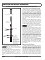
Throughout this guide NOTE, CAUTION and WARNING
will be used.
A NOTE indicates a condition that should be
observed.
A CAUTION indicates a condition that
may result in damage to the vehicle.
!
!
A WARNING indicates a
hazardous condition that
could result in severe
injury or death.
Observe these NOTES, CAUTIONS and WARNINGS;
be aware that servicing a vehicle requires mechanical
skill and a regard for conditions that could be hazardous.
Improper service or repair may damage the vehicle or
render it unsafe.
Engine exhaust from this
product contains chemicals known, in certain
quantities, to cause cancer, birth defects, or other
reproductive harm.
!
!
The exhaust emissions of this vehicles’ engine
complies with regulations set forth by the Environmental Protection Agency (EPA) of the United States of
America (USA) at time of manufacture. Significant fines could
result from modifications or tampering with the engine, fuel,
ignition or air intake systems.
Battery posts, terminals
and related accessories
contain lead and lead
compounds. Wash hands after handling.
!
!
This spark ignition system meets all requirements of the Canadian Interference-Causing
Equipment Regulations.
Ce système d'allumage par étincelle de véhicule respecte
toutes les exigences du Règlement sur le matériel brouilleur
du Canada.
(NOTES, CAUTIONS AND WARNINGS CONTINUED ON INSIDE OF BACK COVER)
OWNER’S MANUAL
AND SERVICE GUIDE
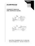
GASOLINE POWERED
REFRESHMENT VEHICLE
REFRESHER® 1200
Starting Model Year 2004
E-Z-GO Division of TEXTRON, Inc. reserves the right to make design changes without obligation to make these changes on units previously sold and the information contained in this manual is subject to change without notice.
E-Z-GO Division of TEXTRON, Inc. is not liable for errors in this manual or for incidental or consequential damages that result from the use of the material in this
manual.
TO CONTACT US
NORTH AMERICA:
TECHNICAL ASSISTANCE & WARRANTY PHONE: 1-800-774-3946, FAX: 1-800-448-8124
SERVICE PARTS PHONE: 1-888-GET-EZGO (1-888-438-3946), FAX: 1-800-752-6175
INTERNATIONAL:
PHONE: 010-1-706-798-4311, FAX: 010-1-706-771-4609
E-Z-GO DIVISION OF TEXTRON, INC., 1451 MARVIN GRIFFIN ROAD, AUGUSTA, GEORGIA USA 30906-3852
Owner’s Manual and Service Guide
Page i
GENERAL INFORMATION
This vehicle has been designed and manufactured in the United States of America (USA) as
a ‘World Vehicle’. The Standards and Specifications listed in the following text originate in
the USA unless otherwise indicated.
The use of non Original Equipment Manufacturer (OEM) approved parts may void the
warranty.
Overfilling battery may void the warranty.
Tampering with or adjusting the governor to permit vehicle to operate at above factory
specifications will void the vehicle warranty.
When servicing engines, all adjustments and replacement components must be per original
vehicle specifications in order to maintain the United States of America Federal and State
emission certification applicable at the time of manufacture.
BATTERY PROLONGED STORAGE
All batteries will self discharge over time. The rate of self discharge varies depending on the
ambient temperature and the age and condition of the batteries.
A fully charged battery will not freeze in winter temperatures unless the temperature falls
below -75° F (-60° C).
Page ii
Owner’s Manual and Service Guide
TABLE OF CONTENTS
SAFETY ................................................................................................................ inside covers
GENERAL INFORMATION ....................................................................................................... ii
SAFETY INFORMATION ......................................................................................................... vii
REFRESHMENT UNIT ............................................................................................................... 1
MOUNT VENDING UNIT TO REFRESHMENT VEHICLE ..................................................................................1
FRONT STRUT INSTALLATION ........................................................................................................................1
WINDSHIELD AND MIRROR INSTALLATION ...................................................................................................1
Fig. 1 Mounting the Refreshment Unit ......................................................................................2
CANOPY FRAME INSTALLATION ....................................................................................................................2
CANOPY INSTALLATION ...................................................................................................................................2
DRAIN VALVE INSTALLATION ..........................................................................................................................2
REFRESHMENT UNIT REMOVAL .....................................................................................................................2
Fig. 2 Front Strut, Windshield and Mirror Installation ................................................................3
REFRESHMENT UNIT OPERATION, MAINTENANCE AND CLEANING ..........................................................3
Operation ................................................................................................................................................3
Cleaning ..................................................................................................................................................3
Fig. 3 Canopy Installation .........................................................................................................4
Fig. 4 Emptying Water from Bins ..............................................................................................5
Maintenance ...........................................................................................................................................5
REFRESHMENT UNIT REPLACEMENT PARTS ...............................................................................................5
BEFORE INITIAL USE .............................................................................................................. 5
Fig. 5 Initial Service Chart .........................................................................................................5
CONTROLS AND INDICATORS ............................................................................................... 5
KEY/LIGHT SWITCH ...........................................................................................................................................6
Fig. 6 Key/Light Switch, Low Oil Pressure Light and Fuel Gauge ............................................6
DIRECTION SELECTOR .....................................................................................................................................6
CHOKE ................................................................................................................................................................6
Fig. 7 Direction Selector ...........................................................................................................6
Fig. 8 Choke .............................................................................................................................6
FUEL GAUGE ......................................................................................................................................................6
LOW OIL PRESSURE INDICATOR LIGHT .........................................................................................................6
ACCELERATOR PEDAL .....................................................................................................................................7
Fig. 9 Accelerator and Brake Controls ......................................................................................7
COMBINATION SERVICE AND PARK BRAKE PEDAL ......................................................................................7
FRONT DISC BRAKES (OPTIONAL) ..................................................................................................................7
HORN ..................................................................................................................................................................7
Fig. 10 Horn Button ...................................................................................................................7
OPERATING THE VEHICLE ..................................................................................................... 7
RUN-IN ................................................................................................................................................................8
Fig. 11 Check Oil Level on Dipstick ..........................................................................................8
COLD STARTING ................................................................................................................................................8
STARTING AND DRIVING ..................................................................................................................................8
STARTING THE VEHICLE ON A HILL ................................................................................................................9
COASTING ..........................................................................................................................................................9
FUEL ....................................................................................................................................................................9
Fig. 12 Fueling ..........................................................................................................................9
BATTERY ............................................................................................................................................................9
LABELS AND PICTOGRAMS ...........................................................................................................................10
SUN TOP AND WINDSHIELD ...........................................................................................................................10
12 VOLT POWER OUTLET ...............................................................................................................................10
Fig. 13 12 Volt Power Outlet ...................................................................................................10
TOWING A TRAILER ........................................................................................................................................10
VEHICLE CLEANING AND CARE .......................................................................................... 10
VEHICLE CLEANING ........................................................................................................................................10
REPAIR .................................................................................................................................... 11
LIFTING THE VEHICLE ....................................................................................................................................11
Fig. 14 Lifting the Vehicle .......................................................................................................11
Owner’s Manual and Service Guide
Page iii
TABLE OF CONTENTS
WHEELS AND TIRES ....................................................................................................................................... 12
Tire Repair ........................................................................................................................................... 12
Wheel Installation ................................................................................................................................. 12
Fig. 15 Wheel Installation ....................................................................................................... 12
LIGHT BULB REPLACEMENT ......................................................................................................................... 13
Fig. 16 Headlight and Turn Signal Bulb Replacement ............................................................ 13
Fig. 17 Tail and Brake Light Bulb Replacement ..................................................................... 13
FUSE REPLACEMENT .................................................................................................................................... 13
VEHICLE WITH A DISCHARGED BATTERY ................................................................................................... 13
TRANSPORTING VEHICLE .................................................................................................... 14
TOWING ........................................................................................................................................................... 14
NEUTRAL LOCK .............................................................................................................................................. 14
Fig. 18 Neutral Lock ............................................................................................................... 14
HAULING .......................................................................................................................................................... 14
SERVICE AND MAINTENANCE .............................................................................................. 15
SERIAL NUMBER LABEL LOCATION ............................................................................................................. 15
PERIODIC SERVICE SCHEDULE .................................................................................................................. 16
Fig. 19 Periodic Service Schedule ......................................................................................... 16
TIRE INSPECTION ........................................................................................................................................... 18
CHECKING THE OIL LEVEL ............................................................................................................................ 18
Fig. 20 Clean Entire Dipstick .................................................................................................. 18
Fig. 21 Check Oil Level on Dipstick ....................................................................................... 18
CHANGING THE OIL ........................................................................................................................................ 18
Fig. 22 Oil Viscosity Chart ...................................................................................................... 19
Fig. 23 Clean Top of Engine .................................................................................................. 19
Fig. 24 Remove Oil Filter ....................................................................................................... 19
Fig. 25 Clean Oil Filter ........................................................................................................... 19
Fig. 26 Blowing Out Oil Filter ................................................................................................. 19
Fig. 27 Add Engine Oil ........................................................................................................... 20
STARTER/GENERATOR BELT TENSION ....................................................................................................... 20
Fig. 28 Checking Belt Tension with Gauge ............................................................................ 20
Fig. 29 Checking Belt Tension Manually ................................................................................ 20
Adjusting the Belt ................................................................................................................................. 21
Fig. 30 Adjusting Belt Tension ............................................................................................... 21
BATTERY CLEANING ...................................................................................................................................... 21
Fig. 31 Preparing Acid Neutralizing Solution .......................................................................... 21
BRAKES ........................................................................................................................................................... 21
Fig. 32 Typical Brake Performance Test ................................................................................ 22
Periodic Brake Test for Mechanical Brakes ......................................................................................... 22
Hydraulic Front Disc Brakes ............................................................................................................................. 22
AIR INTAKE AND COOLING FINS=- ............................................................................................................... 23
Fig. 33 Cleaning Air Intake ..................................................................................................... 23
Fig. 34 Cleaning the Cooling Fins .......................................................................................... 23
REAR AXLE ...................................................................................................................................................... 23
Fig. 35 Add, Check and Drain Rear Axle Lubricant ............................................................... 23
Checking the Lubricant Level ............................................................................................................... 23
AIR CLEANER INSPECTION AND REPLACEMENT ....................................................................................... 23
Canister Type Air Cleaner .................................................................................................................... 23
Cleaning the Air Filter Element ............................................................................................................ 23
Fig. 36 Canister Type Air Cleaner .......................................................................................... 24
LUBRICATION .................................................................................................................................................. 24
Fig. 37 Lubrication Points ....................................................................................................... 24
SPARK PLUGS ................................................................................................................................................. 24
PROLONGED STORAGE ................................................................................................................................ 24
HARDWARE ..................................................................................................................................................... 25
Fig. 38 Torque Specifications ................................................................................................. 25
CAPACITIES AND REPLACEMENT PARTS .................................................................................................... 26
Fig. 39 Capacities and Replacement Parts ............................................................................ 26
GENERAL SPECIFICATIONS .................................................................................................. 27
Page iv
Owner’s Manual and Service Guide
TABLE OF CONTENTS
REFRESHER® 1200...........................................................................................................................................28
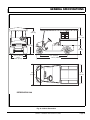
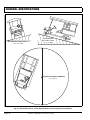
Fig. 40 Vehicle Dimensions .....................................................................................................29
Fig. 41 Vehicle Dimensions, Incline Specifications and Turning Clearance Diameter ............30
LIMITED WARRANTIES........................................................................................................... 31
DOMESTIC WARRANTY ...................................................................................................................................32
INTERNATIONAL WARRANTY (2004) ..............................................................................................................33
FEDERAL EMISSION COMPONENT DEFECT WARRANTY ...........................................................................35
CALIFORNIA EMISSION CONTROL WARRANTY STATEMENT.....................................................................37
DECLARATION OF CONFORMITY (EUROPE ONLY)............................................................ 41
LABELS AND PICTOGRAMS .................................................................................. Appendix A
Owner’s Manual and Service Guide
Page v
TABLE OF CONTENTS
Page vi
Owner’s Manual and Service Guide
SAFETY INFORMATION
This manual has been designed to assist in maintaining the vehicle in accordance with procedures developed by the
manufacturer. Adherence to these procedures and troubleshooting tips will ensure the best possible service from the
product. To reduce the chance of personal injury or property damage, the following must be carefully observed:
Certain replacement parts can be used independently and/or in combination with other accessories to modify an E-ZGO-manufactured vehicle to permit the vehicle to operate at or in excess of 20mph. When an E-Z-GO-manufactured
vehicle is modified an any way by the Distributor, Dealer or customer to operate at or in excess of 20mph, UNDER
FERERAL LAW the modified product will be a Low Speed Vehicle (LSV) subject to the strictures and requirements of
Federal Motor Vehicle Safety Standard 571.500. In these instances, pursuant to Federal law the Distributor or Dealer
MUST equip the product with headlights, rear lights, turn signals, seat belts, top, horn and all other modifications for
LSV’s mandated in FMVSS 571.500, and affix a Vehicle Identification Number to the product in accordance with the
requirements of FMVSS 571.565. Pursuant to FMVSS 571.500, and in accordance with the State laws applicable in the
places of sale and use of the product, the Distributor, Dealer or customer modifying the vehicle also will be the Final
Vehicle Manufacturer for the LSV, and required to title or register the vehicle as mandated by State law.
E-Z-GO will NOT approve Distributor, Dealer or customer modifications converting E-Z-GO products into LSV’s.
The Company, in addition, recommends that all E-Z-GO products sold as personal transportation vehicles BE OPERATED ONLY BY PERSONS WITH VALID DRIVERS LICENSES, AND IN ACCORDANCE WITH APPLICABLE STATE
REQUIREMENTS. This restriction is important to the SAFE USE AND OPERATION of the product. On behalf of E-ZGO, I am directing that E-Z-GO Branch personnel, Distributors and Dealers advise all customers to adhere to this
SAFETY RESTRICTION, in connection with the use of all products, new and used, the Distributor or Dealer has reason to believe may be operated in personal transportation applications.
Information on FMVSS 571.500 can be obtained at Title 49 of the Code of Federal Regulations, section 571.500, or
through the Internet at the website for the U.S. Department of Transportation - at Dockets and Regulation, then to Title
49 of the Code of Federal Regulations (Transportation).
GENERAL
Many vehicles are used for a variety of tasks beyond the original intended use of the vehicle; therefore, it is impossible
to anticipate and warn against every possible combination of circumstances that may occur. No warnings can take the
place of good common sense and prudent driving practices.
Good common sense and prudent driving practices do more to prevent accidents and injury than all of the warnings
and instructions combined. The manufacturer strongly suggests that all users and maintenance personnel read this
entire manual paying particular attention to the CAUTIONS and WARNINGS contained therein.
If you have any questions regarding this vehicle, contact your closest representative or write to the address on the
back cover of this publication, Attention: Product Service Department.
The manufacturer reserves the right to make design changes without obligation to make these changes on units previously sold and the information contained in this manual is subject to change without notice.
The manufacturer is not liable for errors in this manual or for incidental or consequential damages that result from the
use of the material in this manual.
This vehicle conforms to the current applicable standard(s) for safety and performance requirements.
Owner’s Manual and Service Guide
Page vii
SAFETY INFORMATION
These vehicles are designed and manufactured for off-road use. They do not conform to Federal Motor Vehicle Safety
Standards of the United States of America (USA) and are not equipped for operation on public streets. Some communities may permit these vehicles to be operated on their streets on a limited basis and in accordance with local ordinances.
Refer to GENERAL SPECIFICATIONS for vehicle seating capacity.
Never modify the vehicle in any way that will alter the weight distribution of the vehicle, decrease its stability
or increase the speed beyond the factory specification. Such modifications can cause serious personal injury
or death. Modifications that increase the speed and/or weight of the vehicle will extend the stopping distance and may
reduce the stability of the vehicle. Do not make any such modifications or changes. The manufacturer prohibits and
disclaims responsibility for any such modifications or any other alteration which would adversely affect the safety of the
vehicle.
Vehicles that are capable of higher speeds must limit their speed to no more than the speed of other vehicles when
used in a golf course environment. Additionally, speed should be further moderated by the environmental conditions,
terrain and common sense.
GENERAL OPERATION
Always:
• Use the vehicle in a responsible manner and maintain the vehicle in safe operating condition.
• Read and observe all warnings and operation instruction labels affixed to the vehicle.
• Follow all safety rules established in the area where the vehicle is being operated.
• Reduce speed to compensate for poor terrain or conditions.
• Apply service brake to control speed on steep grades.
• Maintain adequate distance between vehicles.
• Reduce speed in wet areas.
• Use extreme caution when approaching sharp or blind turns.
• Use extreme caution when driving over loose terrain.
• Use extreme caution in areas where pedestrians are present.
MAINTENANCE
Always:
• Maintain the vehicle in accordance with the manufacturer’s periodic service schedule.
• Ensure that repairs are performed by those that are trained and qualified to do so.
• Follow the manufacturer’s maintenance procedures for the vehicle. Be sure to disable the vehicle before performing
any maintenance. Disabling includes removing the key from the key switch and removal of a battery wire.
• Insulate any tools used within the battery area in order to prevent sparks or battery explosion caused by shorting the
battery terminals or associated wiring. Remove the battery or cover exposed terminals with an insulating material.
Page viii
Owner’s Manual and Service Guide
SAFETY INFORMATION
• Use specified replacement parts. Never use replacement parts of lesser quality.
• Use recommended tools.
• Determine that tools and procedures not specifically recommended by the manufacturer will not compromise the
safety of personnel nor jeopardize the safe operation of the vehicle.
• Support the vehicle using wheel chocks and jack stands. Never get under a vehicle that is supported by a jack. Lift
the vehicle in accordance with the manufacturer’s instructions.
• Empty the fuel tank or plug fuel hoses to prevent fuel leakage.
• Maintain the vehicle in an area away from exposed flame or persons who are smoking.
• Be aware that a vehicle that is not performing as designed is a potential hazard and must not be operated.
• Test drive the vehicle after any repairs or maintenance. All tests must be conducted in a safe area that is free of both
vehicular and pedestrian traffic.
• Replace damaged or missing warning, caution or information labels.
• Keep complete records of the maintenance history of the vehicle.
The manufacturer cannot anticipate all situations, therefore people attempting to maintain or repair the vehicle must
have the skill and experience to recognize and protect themselves from potential situations that could result in severe
personal injury or death and damage to the vehicle. Use extreme caution and, if unsure as to the potential for injury,
refer the repair or maintenance to a qualified mechanic.
VENTILATION
Always store gasoline vehicles in a well ventilated area. Ventilation prevents gasoline fumes from accumulating.
Never fuel a vehicle in an area that is subject to flame or spark. Pay particular attention to natural gas or propane water
heaters and furnaces.
Never work around or operate a vehicle in an environment that does not ventilate exhaust gases from the area. Carbon
monoxide is a dangerous gas that can cause unconsciousness and is potentially lethal.
Owner’s Manual and Service Guide
Page ix
SAFETY INFORMATION
Notes:
Page x
Owner’s Manual and Service Guide
SAFETY INFORMATION
Read all of manual to become thoroughly familiar with this vehicle. Pay particular attention to all Notes, Cautions and Warnings
GENERAL
The following text is provided as recommended by part II
of American Society of Mechanical Engineers / American
National Standards Institute (ASME/ANSI) B56.8-1988.
The manufacturer strongly endorses the contents of this
specification.
addition which affects capacity or safe operation, or
make any change not in accordance with the owner’s
manual without the manufacturer’s prior written authorization. Where authorized modifications have been made,
the user shall ensure that capacity, operation, warning,
and maintenance instruction plates, tags, or decals are
changed accordingly.
PART II
FOR THE USER
4.3.3 As required under paras. 4.3.1 or 4.3.2, the
manufacturer shall be contacted to secure new nameplates, warnings, or instructions which shall then be
affixed in their proper place on the carrier.
4 GENERAL SAFETY PRACTICES
4.4
4.1
Introduction
4.1.1 Like other machines, carriers can cause injury
if improperly used or maintained. Part II contains broad
safety practices applicable to carrier operations. Before
operation, the user shall establish such additional specific safety practices as may reasonably be required for
safe operation.
4.2
Stability
4.2.1
Experience has shown that this vehicle, which
complies with this standard, is stable when properly
operated and when operated in accordance with specific
safety rules and practices established to meet actual
operating terrain and conditions. However, improper
operation, faulty maintenance, or poor housekeeping
may contribute to a condition of instability and defeat the
purpose of the standard. Some of the conditions which
may affect stability are failure of the user to follow safety
practices; also, ground and floor conditions, grade,
speed, loading, the operation of the carrier with improper
loads, battery weight, dynamic and static forces, and the
judgement exercised by the carrier operator.
(a) The user shall train carrier operators to adhere
strictly to the operating instructions stated in this Standard.
(b) The user shall survey specific operating conditions
and environment, and establish and train carrier operators to comply with additional, specific safety practices.
4.3
Nameplates, Markings, Capacity, and Modifications
4.3.1 The user shall maintain in a legible condition
all nameplates, warnings, and instructions which are
supplied by the manufacturer.
4.3.2
The user shall not perform any modification or
Fuel Handling and Storage
4.4.1 The user shall supervise the storage and handling of liquid fuels (when used) to be certain that it is in
accordance with appropriate paragraphs of American
National Standards Institute/National Fire Protection
Association (ANSI/NFPA) 505 and ANSI/NFPA 30.
4.4.2 Storage and handling of liquefied petroleum
gas fuels shall be in accordance with appropriate paragraphs of ANSI/NFPA 505 and ANSI/NFPA 58. If such
storage or handling is not in compliance with these standards, the user shall prevent the carrier from being used
until such storage and handling is in compliance with
these standards.
4.5
Changing and Charging Storage Batteries for
Electric Personnel and Burden Carriers
4.5.1 The user shall require battery changing and
charging facilities and procedures to be in accordance
with appropriate paragraphs of ANSI/NFPA 505.
4.5.2 The user shall periodically inspect facilities
and review procedures to be certain that appropriate
paragraphs of ANSI/NFPA 505, are strictly complied with,
and shall familiarize carrier operators with it.
4.6
Hazardous Locations
4.6.1 The user shall determine the hazard classification of the particular atmosphere or location in which
the carrier is to be used in accordance with ANSI/NFPA
505.
4.6.2 The user shall permit in hazardous areas only
those carriers approved and of the type required by
ANSI/NFPA 505.
4.7
Lighting for Operating Areas
4.7.1 The user, in accordance with his responsibility
to survey the environment and operating conditions, shall
determine if the carrier requires lights and, if so, shall
Owner’s Manual and Service Guide
Page xi
SAFETY INFORMATION
Read all of manual to become thoroughly familiar with this vehicle. Pay particular attention to all Notes, Cautions and Warnings
equip the carrier with appropriate lights in accordance
with the manufacturer’s recommendations.
5.2.3 The user should include in the operators’ training program the following:
4.8
(a) instructional material provided by the manufacturer;
Control of Noxious Gases and Fumes
4.8.1 When equipment powered by internal combustion engines is used in enclosed areas, the atmosphere shall be maintained within limits specified in the
American Conference of Governmental Industrial
Hygienists publication, “Threshold Limit Values for
Chemical Substances and Physical Agents in the Workroom Environment”. This shall be accomplished by ventilation provided by the user, and/or the installation, use,
and proper maintenance of emission control equipment
recommended or provided by the manufacturer of the
equipment.
4.9
Warning Device(s)
4.9.1 The user shall make periodic inspections of
the carrier to be certain that the sound-producing and/or
visual device(s) are maintained in good operating condition.
(b) emphasis on safety of passengers, material loads,
carrier operator, and other employees;
(c) general safety rules contained within this Standard
and the additional specific rules determined by the user
in accordance with this Standard, and why they were formulated;
(d) introduction of equipment, control locations and
functions, and explanation of how they work when used
properly and when used improperly, and surface conditions, grade, and other conditions of the environment in
which the carrier is to be operated;
(e) operational performance tests and evaluations
during, and at completion of, the program.
5.3
Personnel and Burden Carrier Operator
Responsibility
4.9.2 The user shall determine if operating conditions require the carrier to be equipped with additional
sound-producing and/or visual devices and be responsible for providing and maintaining such devices, in accordance with the manufacturer’s recommendations.
5.3.1 Operators shall abide by the following safety
rules and practices in paras. 5.4, 5.5, 5.6, and 5.7.
5 OPERATING SAFETY RULES AND
PRACTICES
5.4.2 Riding on the carrier by persons other than the
operator is authorized only on personnel seat(s) provided
by the manufacturer. All parts of the body shall remain
within the plan view outline of the carrier.
5.1
Personnel and Burden Carrier Operator
Qualifications
5.1.1 Only persons who are trained in the proper
operation of the carrier shall be authorized to operate the
carrier. Operators shall be qualified as to visual, auditory,
physical, and mental ability to safely operate the equipment according to Section 5 and all other applicable
parts of this Standard.
5.2
Personnel and Burden Carrier Operators’
Training
5.2.1 The user shall conduct an operators’ training
program.
5.2.2 Successful completion of the operators’ training program shall be required by the user before operation of the carrier. The program shall be presented in its
entirety to all new operators and not condensed for those
claiming previous experience.
Page xii
5.4
General
5.4.1 Safeguard the pedestrians at all times. Do not
drive carrier in a manner that would endanger anyone.
5.4.3 When a carrier is to be left unattended, stop
carrier, apply the parking brake, stop the engine or turn
off power, turn off the control or ignition circuit, and
remove the key if provided. Block the wheels if machine
is on an incline.
5.4.4 A carrier is considered unattended when the
operator is 25 ft. (7.6 m) or more from the carrier which
remains in his view, or whenever the operator leaves the
carrier and it is not within his view. When the operator is
dismounted and within 25 ft. (7.6 m) of the carrier still in
his view, he still must have controls neutralized, and the
parking brake(s) set to prevent movement.
5.4.5 Maintain a safe distance from the edge of
ramps and platforms.
5.4.6 Use only approved carriers in hazardous locations, as defined in the appropriate safety standards.
5.4.7
Report all accidents involving personnel,
Owner’s Manual and Service Guide
SAFETY INFORMATION
Read all of manual to become thoroughly familiar with this vehicle. Pay particular attention to all Notes, Cautions and Warnings
building structures, and equipment.
5.4.8
rier.
Operators shall not add to, or modify, the car-
5.4.9 Carriers shall not be parked or left unattended
such that they block or obstruct fire aisles, access to
stairways, or fire equipment.
5.5
Traveling
5.5.1 Observe all traffic regulations, including authorized speed limits. Under normal traffic conditions keep
to the right. Maintain a safe distance, based on speed of
travel, from a carrier or vehicle ahead; and keep the carrier under control at all times.
5.5.2 Yield the right of way to pedestrians, ambulances, fire trucks, or other carriers or vehicles in emergency situations.
5.5.3 Do not pass another carrier or vehicle traveling in the same direction at intersections, blind spots, or
at other dangerous locations.
5.5.4 Keep a clear view of the path of travel,
observe other traffic and personnel, and maintain a safe
clearance.
5.5.5 Slow down or stop, as conditions dictate, and
activate the sound-producing warning device at cross
aisles and when visibility is obstructed at other locations.
5.5.6
Ascend or descend grades slowly.
5.5.7 Avoid turning, if possible, and use extreme
caution on grades, ramps, or inclines; normally travel
straight up and down.
5.5.8 Under all travel conditions the carrier shall be
operated at a speed that will permit it to be brought to a
stop in a safe manner.
5.5.9 Make starts, stops, turns, or direction reversals in a smooth manner so as not to shift the load,
endanger passengers, or overturn the carrier.
5.5.13 Avoid running over loose objects, potholes,
and bumps.
5.5.14 To negotiate turns, reduce speed to improve
stability, then turn hand steering wheel or tiller in a
smooth, sweeping motion.
5.6
Loading
5.6.1 Handle only stable and safely arranged loads.
When handling off-center loads which cannot be centered, operate with extra caution.
5.6.2 Handle only loads within the capacity of the
carrier as specified on the nameplate.
5.6.3 Handle loads exceeding the dimensions used
to establish carrier capacity with extra caution. Stability
and maneuverability may be adversely affected.
5.7
Operator Care of Personnel and Burden
Carriers
5.7.1 At the beginning of each shift during which the
carrier will be used, the operator shall check the carrier
condition and inspect the tires, warning devices, lights,
battery(s), speed and directional controllers, brakes, and
steering mechanism. If the carrier is found to be in need
of repair, or in any way unsafe, the matter shall be
reported immediately to the designated authority and the
carrier shall not be operated until it has been restored to
safe operating condition.
5.7.2 If during operation the carrier becomes unsafe
in any way, the matter shall be reported immediately to
the designated authority, and the carrier shall not be
operated until it has been restored to safe operating condition.
5.7.3 Do not make repairs or adjustments unless
specifically authorized to do so.
5.7.4 The engine shall be stopped and the operator
shall leave the carrier while refueling.
5.5.10 Do not indulge in dangerous activities, such as
stunt driving or horseplay.
5.7.5 Spillage of oil or fuel shall be carefully and
completely absorbed or evaporated and fuel tank cap
replaced before starting engine.
5.5.11 Slow down when approaching, or on, wet or
slippery surfaces.
5.7.6 Do not operate a carrier with a leak in the fuel
system or battery(s).
5.5.12 Do not drive carrier onto any elevator unless
specifically authorized to do so. Approach elevators
slowly, and then enter squarely after the elevator car is
properly leveled. Once on the elevator, neutralize the
controls, shut off power, and set parking brakes. It is
advisable that all other personnel leave the elevator
before a carrier is allowed to enter or exit.
5.7.7 Do not use open flames for checking electrolyte level in storage battery(s) or liquid level in fuel tanks.
6 MAINTENANCE PRACTICES
6.1
Introduction
Owner’s Manual and Service Guide
Page xiii
SAFETY INFORMATION
Read all of manual to become thoroughly familiar with this vehicle. Pay particular attention to all Notes, Cautions and Warnings
6.1.1 Carriers may become hazardous if maintenance is neglected. Therefore, maintenance facilities,
trained personnel, and procedures shall be provided.
Such facilities may be on or off the premises.
6.2
Maintenance Procedures
6.2.1 Maintenance and inspection of all carriers
shall be performed in conformance with the manufacturer’s recommendations and the following practices.
(a) A scheduled preventive maintenance, lubrication,
and inspection system shall be followed.
(b) Only qualified and authorized personnel shall be
permitted to maintain, repair, adjust, and inspect carriers.
(c) Before undertaking maintenance or repair, follow
the manufacturer’s recommendations for immobilizing
the carrier.
(d) Block chassis before working underneath it.
(e) Before disconnecting any part of the engine fuel
system of a gasoline or diesel powered carrier with gravity feed fuel systems, be sure shutoff valve is closed, and
run engine until fuel system is depleted and engine stops
running.
(f) Before disconnecting any part of the engine fuel
system of LP gas powered carriers, close the LP gas cylinder valve and run the engine until fuel in the system is
depleted and the engine stops running.
(g) Operation to check performance of the carrier shall
be conducted in an authorized area where safe clearance exists.
(h) Before commencing operation of the carrier, follow
the manufacturer’s instructions and recommended procedures.
(i) Avoid fire hazards and have fire protection equipment present in the work area. Do not use an open flame
to check level or leakage of fuel, battery electrolyte, or
coolant. Do not use open pans of fuel or flammable
cleaning fluids for cleaning parts.
inspected to ensure that maintenance preserves the original approved safe operating features.
(n) Fuel systems shall be checked for leaks and condition of parts. If a leak is found, action shall be taken to
prevent the use of the carrier until the leak has been
eliminated.
(o) The carrier manufacturer’s capacity, operation,
and maintenance instruction plates, tags, or decals shall
be maintained in legible condition.
(p) Batteries, motors, speed and directional controllers, limit switches, protective devices, electrical conductors, and connections shall be inspected and maintained
in conformance with manufacturers recommended procedures.
(q) Carriers shall be kept in a clean condition to minimize fire hazards and facilitate detection of loose or
defective parts.
(r) Modifications and additions which affect capacity
and safe machine operation shall not be performed by
the customer or user without manufacturer’s prior written
authorization; where authorized modifications have been
made, the user shall ensure that capacity, operation,
warning, and maintenance instruction plates, tags, or
decals are changed accordingly.
(s) Care shall be taken to ensure that all replacement
parts are interchangeable with the original parts and of a
quality at least equal to that provided in the original
equipment.
END OF ASME/ANSI B56.8 - 1988 TEXT
(j) Properly ventilate the work area.
(k) Handle LP gas cylinders with care. Physical damage, such as dents, scrapes, or gouges, may dangerously weaken the tank and make it unsafe for use.
(l) Brakes, steering mechanisms, speed and directional control mechanisms, warning devices, lights, governors, guards, and safety devices shall be inspected
regularly and maintained in a safe operating condition.
(m)
Special carriers or devices designed and
approved for hazardous area operation shall be
Page xiv
Owner’s Manual and Service Guide
OPERATION AND SERVICE INFORMATION
Read all of manual to become thoroughly familiar with this vehicle. Pay particular attention to all Notes, Cautions and Warnings
Thank you for purchasing this vehicle. Before driving the
vehicle, we ask you to spend some time reading this
Owner’s Manual and Service Guide. This guide contains
the information that will assist you in maintaining this
highly reliable vehicle. Some illustrations may show
items that are optional for your vehicle. This guide covers
the operation of several vehicles; therefore, some pictorial views may not represent your vehicle. Physical differences in controls will be illustrated.
This vehicle has been designed and manufactured as a
‘World Vehicle’. Some countries have individual requirements to comply with their specifications; therefore,
some sections may not apply in your country.
Most of the service procedures in this guide can be
accomplished using common automotive hand tools.
Contact your service representative on servicing the
vehicle in accordance with the Periodic Service Schedule.
Service Parts Manuals and Technician’s Repair and Service Manuals are available from a local Distributor, an
authorized Branch or the Service Parts Department.
When ordering parts or requesting information for your
vehicle, provide vehicle model, serial number and manufacture code.
to the unit. Be sure hands and fingers are clear of unit
while placing unit on frame.
The refreshment unit is shipped on a pallet. While resting
on pallet, the unit should be handled with a forklift. If a
forklift is not available, be sure an adequate number of
assistants are available to safely lift the vending unit.
Orient vending unit so that door on unit will be facing the
rear of the vehicle when unit is placed on the mounting
frame (Ref. Fig. 1 on page 2). Using a forklift, lift the
refreshment unit and pallet level with the bed of refreshment vehicle. Lift the refreshment unit off of the pallet and
carefully place it onto the mounting frame on vehicle.
Align the four mounting holes on refreshment unit with
corresponding holes on vehicle mounting frame. Secure
unit to frame with four 5/16 - 18 X 1 1/4" bolts (item 1),
eight 5/16" flat washers (item 2) and four 5/16 - 18 lock
nuts (item 3). Tighten hardware firmly.
FRONT STRUT INSTALLATION
The vending unit is equipped with two beverage compartments, a cold storage compartment, a consumable ice
compartment, a food display cabinet, two cup dispensers
and a trash bin. Available accessories are listed in illustration (Ref. Fig. 1 on page 2).
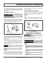
Position front strut (item 4) and braces (item 5) as shown
(Ref. Fig. 2 on page 3) and secure to vehicle at each side
of the cowl with four 5/16 - 18 X 2 1/2" bolts (item 6), four
5/16" lock washers (item 7), two spacers (item 8) and six
3/8" flat washers (item 9). Secure top of braces with two
5/16 - 18 X 2 1/4" bolts (item 10), four 5/16" lock washers
(item 11) and two 5/16 - 18 lock nuts (item 12). Attach
canopy frame mounting plate (item 13) to front strut
using two 1/4 - 20 X 1 1/2" bolts (item 14), four 1/4" flat
washers (item 15) and two 1/4 - 20 lock nuts (item 16) as
shown. Tighten hardware firmly.
Tool List
WINDSHIELD AND MIRROR INSTALLATION
REFRESHMENT UNIT
Qty. Required
Ratchet, 3/8" drive....................................................... 1
Socket, 1/2", 3/8" drive................................................ 1
Wrench, 1/2" ............................................................... 1
Phillips screwdriver ..................................................... 1
Wrench, 7/16" ............................................................. 1
Drill .............................................................................. 1
Socket adapter, 1/4" drive ........................................... 1
Socket, 5/16", 1/4" drive.............................................. 1
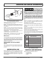
MOUNT VENDING UNIT TO REFRESHMENT
VEHICLE
The vending unit is
heavy. Care and proper
lifting equipment and
procedures must be used when installing unit to
reduce the possibility of severe injury and/or damage
!
!
Typical operation of a
Refresher® vehicle on a
golf course may expose
operator to possibility of being struck by a golf ball.
Always operate vehicle with windshield in place.
!
!
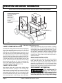
Insert two bumpers (item 17) and four grommets (item
18) into holes in windshield (item 19) as shown (Ref. Fig.
2 on page 3). Position windshield and mirror brackets
(item 20) as shown. Secure windshield and mirror brackets to front strut with four 1/4 - 20 X 1 3/4" bolts (item 21),
four spacers (item 22), four 1/4" washers (item 23) and
four 1/4 - 20 lock nuts (item 24). Tighten hardware firmly.
Thread mirrors (item 25) onto mirror brackets and tighten
securely.
Owner’s Manual and Service Guide
Page 1
OPERATION AND SERVICE INFORMATION
Read all of manual to become thoroughly familiar with this vehicle. Pay particular attention to all Notes, Cautions and Warnings
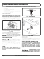
Available Refreshment Unit
Accessories Include:
Sign Boards
Condiment Tray
Bottle Caddy
Mini Bottle Carrier
Humidor
Credit Card Machine Mount
Cash Drawer
1
2
Consumable Ice
(This Compartment Only)
Ref Rfi 1
Fig. 1 Mounting the Refreshment Unit
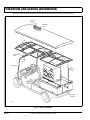
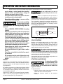
CANOPY FRAME INSTALLATION
Orient the two canopy frame sections end to end aligning
five existing mounting holes as shown (Ref. Fig. 3 on
page 4) and fasten together with five 1/4 - 20 X 2" bolts
(item 26), ten 1/4" flat washers (item 27) and five 1/4 - 20
lock nuts (item 28). Orient the assembled canopy frame
as shown and rest front of frame on top mounting plate
and rear of frame on refreshment unit struts. Secure canopy frame to refreshment unit struts with two 1/4 - 20 X 1
1/4" bolts (item 29), four 1/4" flat washers (item 30) and
two 1/4 - 20 lock nuts (item 31) as shown. Secure canopy
frame to front strut with two 1/4 - 20 X 2" bolts (item 32),
four 1/4" flat washers (item 33) and two 1/4 - 20 lock nuts
(item 34) as shown. Tighten hardware firmly.
Secure each mounting flap to inner surface of canopy
frame with #10 X 1/2" self tapping screws (item 35)
evenly spaced approximately 9" apart as shown. To prevent “gathering” of canopy material during installation,
use the aid of assistants to hold the canopy taut while
securing to canopy frame. For best results, begin securing the canopy at the middle of each side and proceed to
each end of frame.
DRAIN VALVE INSTALLATION
CANOPY INSTALLATION
Locate the drain hose ends and drain valve mounting
holes under the rear of unit. Orient each drain valve
assembly with spigot facing rearward. Attach each valve
assembly to unit with two 1/4 - 20 X 3/4" screws. Slide
the hose clamps onto the end of each drain hose. Push
the hose ends onto the drain valves and tighten clamps.
Wipe canopy frame with a clean cloth. Unfold canopy
and locate clearance openings in the mounting flap.
Drape canopy over frame and orient canopy on frame so
that clearance openings match strut attachment points
and canopy frame juncture (Ref. Fig. 3 on page 4). With
the aid of assistants, pull canopy taut over canopy frame.
Fold mounting flap up inside canopy frame as shown.
REFRESHMENT UNIT REMOVAL
The vending unit is
!
! heavy. Care and proper
lifting equipment and
procedures must be used when removing unit to
reduce the possibility of severe injury and/or damage
Page 2
Owner’s Manual and Service Guide
OPERATION AND SERVICE INFORMATION
Read all of manual to become thoroughly familiar with this vehicle. Pay particular attention to all Notes, Cautions and Warnings
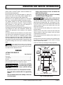
Canned Beverage Compartments - The canned beverage compartments are designed to carry canned beverages and cooling ice. Cold snacks (sandwiches, fruit,
candy etc.) can also be served from these compartments
by inserting the product into a plastic food container. Precooling the canned beverages will minimize the amount
of ice required to keep the product cool. Maintaining ice
in the canned beverage compartment when the container
is not in service will help to maintain a colder temperature
when the unit is put back into service.
13
14
15
21 23
18
22
4
19
17
20 18 24
25
15
16
12
11
10
6
5
8
9
Consumable Ice Compartment - The consumable ice
compartment, located in the rear driver side of the beverage container is to be used for consumable ice only (Ref.
Fig. 1 on page 2). This compartment is equipped with it's
own drain per FDA requirements and should not be used
for canned goods or other products.
Trash Compartment - The trash compartment is located
in the rear of the vehicle. The aluminum trash bin should
be lined with a disposable plastic bag to maintain cleanliness. The trash bin is removable from the rear door only.
7
9
Ref Rfi 2
Fig. 2 Front Strut, Windshield and Mirror Installation
to the unit. Be sure hands and fingers are clear of unit
while lowering.
The drain valves protrude below the
frame of the unit and can be damaged if
the unit is removed from pallet and placed directly onto a flat
surface. Remove drain valves from refreshment unit before
removing unit.
Refreshment unit removal is the reverse order of installation. The unit should be lifted onto a pallet being careful
not to damage drains and then handled with a forklift. If a
forklift is not available, be sure an adequate number of
assistants are available to safely lift the vending unit and
pallet.
REFRESHMENT UNIT OPERATION, MAINTENANCE AND CLEANING
Operation
Consumable ice must be
!
! stored in the rear driver
side compartment only.
Clean this compartment and the driver side drain
valve before and after each use to reduce the possible
contamination of consumable ice.
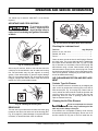
Drains - The two spigot valves, located under the rear of
the beverage container, drain the compartments. To open
the valves, simply turn the valve handles away from the
vehicle (Ref. Fig. 4 on page 5). To close the valves, turn
the valve handles to a position parallel with the vehicle. It
is recommended that the valves be left in an open position while the vehicle is in service.
Cup Dispensers - The cup dispensers are designed to
carry cups ranging from 14 to 20 ounces. To adjust the
cup dispenser for your size and type of cup, remove the
outer collar, insert a sleeve of cups into the dispenser,
and turn the adjusting screw until the cups are securely
held in the cup dispenser. Re-install the outer collar.
Shelves are to be used for any type of dry good such as
chips, peanuts, hats, golf balls etc.
Air Pot - The three one gallon Air Pots are for serving hot
or cold beverages.
Cleaning
Interior Aluminum Surfaces - The interior surfaces
should be cleaned on a daily basis using a soap and
water solution. Thoroughly rinse after cleaning.
Exterior Painted Surfaces - The painted surfaces
should be cleaned on a daily basis using a soap and
water solution.
Exterior Aluminum Surfaces - The aluminum surfaces
should also be cleaned on a daily basis using a soap and
water solution. Periodic cleaning with an aluminum or
Owner’s Manual and Service Guide
Page 3
OPERATION AND SERVICE INFORMATION
Read all of manual to become thoroughly familiar with this vehicle. Pay particular attention to all Notes, Cautions and Warnings
Canopy
Frame 24
Mounting
Flap
20
21
22
21
21
Top Mounting
Plate
20
22 21
21
22
Front Strut
21
23
ID Plate
(Inside)
Ref Rfi 3
Fig. 3 Canopy Installation
Page 4
Owner’s Manual and Service Guide
OPERATION AND SERVICE INFORMATION
Read all of manual to become thoroughly familiar with this vehicle. Pay particular attention to all Notes, Cautions and Warnings
n
Ope
C
lo
se
d
Clear Hose
Ref Rfi 4
Fig. 4 Emptying Water from Bins
stainless steel cleaner is recommended. We recommend
ZEP Stainless Steel Polish or equal.
Drains - The drains should be flushed with a hose on a
daily basis. Periodically, the drains should be cleaned
and sanitized.
Acrylic - The clear acrylic doors should be cleaned daily
with a soap and water solution. Dry with a clean damp
chamois. Do not use window-cleaning sprays.
Polypropylene - The polypropylene doors should be
cleaned daily with a soap and water solution.
Canopy Cover - Periodically hose off the fabric with
fresh water and allow to dry on the canopy frame.
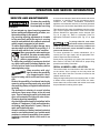
Maintenance
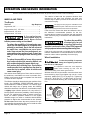
Hydrogen gas is generated as a natural part of the
lead acid battery charging process. A 4% concentration of hydrogen gas is
explosive and could cause severe injury or death.
Charging must take place in an area that is adequately ventilated (minimum of 5 air exchanges per hour).
!
!
To reduce the chance of battery explosion that could
result in severe injury or death, never smoke around
or charge batteries in an area that has open flame or
electrical equipment that could cause an electrical
arc.
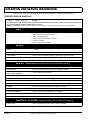
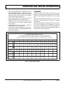
Before a new vehicle is put into operation, the items
shown in the INITIAL SERVICE CHART must be performed (Ref. Fig. 5 on page 5).
Vehicle battery must be fully charged before initial use.
Check for correct tire inflation. See GENERAL SPECIFICATIONS.
Check for oil or fuel leaks that could have developed in
shipment from the factory.
Determine and record braking distance required to stop
vehicle for future brake performance tests.
Remove the protective clear plastic, that protect the seat
bottom and back rest during shipping, before placing the
vehicle in service.
ITEM
The door latches and locks will require periodic tightening, adjusting and lubricating with a silicone spray lubricant. We recommend that this be done every two weeks.
Tightening of all screws, nuts and bolts should be accomplished on a regular basis.
REFRESHMENT UNIT REPLACEMENT
PARTS
When ordering refreshment unit replacement parts, reference manufacturer’s I. D. plate located in trash bin compartment.
SERVICE OPERATION
Battery
Charge battery
Seats
Remove protective plastic covering
Brakes
Check operation and adjust if necessary
Check hydraulic brake fluid level if equipped
Establish acceptable stopping distance
Tires
Check air pressure (see SPECIFICATIONS)
Fuel
Fill tank with correct fuel
Engine
Check oil level
Ref Isc 6
Fig. 5 Initial Service Chart
BEFORE INITIAL USE
Read, understand and follow the safety label on the
instrument panel. Be sure you understand how to operate the vehicle, its equipment and how to use it safely.
Maintaining good performance depends to a large extent
on the operator.
CONTROLS AND INDICATORS
Vehicle controls and indicators consist of:
• key/light switch
• direction selector
• choke
Owner’s Manual and Service Guide
Page 5
OPERATION AND SERVICE INFORMATION
Read all of manual to become thoroughly familiar with this vehicle. Pay particular attention to all Notes, Cautions and Warnings
•
•
•
•
•
fuel gauge
low oil pressure indicator light
accelerator pedal
combination service and park brake pedal with
front disc brakes (optional)
horn
Reverse
Forward
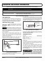
KEY/LIGHT SWITCH
Ref Dsl 2
Located on the dash panel, this switch enables the basic
electrical system of the vehicle to be turned on and off by
turning the key. To prevent inadvertent operation of the
vehicle when left unattended, the key should be turned to
the ‘OFF’ position and removed (Ref. Fig. 6 on page 6).
Key/Light Switch
Fig. 7 Direction Selector
Fuel
Gauge
OFF
ON
E
F
FUE
L
Ref Kes 2
Low Oil Pressure
Indicator Light
Fig. 6 Key/Light Switch, Low Oil Pressure Light and
Fuel Gauge
If the vehicle is equipped with lights, the key switch has a
position to operate them, indicated by the light icon.
Ref Chk 1
If the vehicle is equipped with factory installed
custom accessories, some accessories remain
operational with the key switch in the ‘OFF’ position.
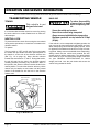
DIRECTION SELECTOR
To reduce the possibility of component
damage, the vehicle must be completely stopped before moving the direction selector.
Located on the seat support panel, this lever permits the
selection of either ‘F’ (forward) or ‘R’ (reverse) (Ref. Fig.
7 on page 6). Vehicle should be left in ‘F’ when unattended.
CHOKE
The choke is used to aid cold starting (Ref. Fig. 8 on
page 6). See COLD STARTING section for operating
instructions.
Page 6
Choke
Fig. 8 Choke
FUEL GAUGE
The fuel gauge (if equipped) will either be located on the
dash panel (electric) (Ref. Fig. 6 on page 6) or directly on
the fuel tank (mechanical).
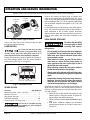
LOW OIL PRESSURE INDICATOR LIGHT
A low oil pressure indicator light is located on the dash
panel (Ref. Fig. 6 on page 6). The light illuminates when
the oil pressure is low. Check oil level. If oil level is
between ADD and FULL mark on dipstick, a mechanical
problem exists within the engine and the vehicle must
not be driven. Contact a local distributor or authorized
branch.
To prevent engine damage, do not operate engine until oil pressure is corrected. Do not overfill engine. Too much oil may cause smoking or
allow oil to enter the air filter enclosure.
Owner’s Manual and Service Guide
OPERATION AND SERVICE INFORMATION
Read all of manual to become thoroughly familiar with this vehicle. Pay particular attention to all Notes, Cautions and Warnings
If oil level is below ADD mark on dipstick, add oil to bring
level to FULL mark. Drive vehicle a short distance and
check oil pressure. If oil light does not come on, continue
to use vehicle.
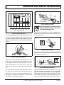
ACCELERATOR PEDAL
Unintentional movement
of the accelerator pedal
will release the park
brake and may cause the vehicle to move which could
result in severe injury or death.
!
!
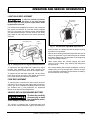
OPTIONAL FRONT DISC BRAKES
The front disc brakes activate as the brake pedal
reaches the ‘park’ or ’latch’ position. Depressing the
brake pedal further will increase the effectiveness of the
front brakes.
HORN
The horn is operated by pushing the horn button located
on the floor to the left of the brake pedal (Ref. Fig. 10 on
page 7).
Horn
H
With the key switch ‘ON’, depressing the accelerator
pedal starts the engine. When the pedal is released, the
engine will stop (Ref. Fig. 9 on page 7). To stop the vehicle more quickly, depress the service brake.
Use the lower section of the brake pedal to operate the
service brake system.
Park
Brake
PARK
ORN
Service
Brake
PARK
Ref Hor 1
Fig. 10 Horn Button
Accelerator
Ref Abc 1
OPERATING THE VEHICLE
Fig. 9 Accelerator and Brake Controls
If key switch is ‘ON’ and park brake is set, depressing the
accelerator inadvertently will release the park brake and
will cause the vehicle to move which could cause severe
injury or death.
Depressing the accelerator pedal will release the park
brake if it is engaged. This is a feature to assure the vehicle is not driven with the park brake engaged. Depressing the accelerator pedal is not the preferred method of
releasing the park brake.
Depressing the lower section of the brake
pedal is the preferred method of releasing the
park brake to assure the longest service life of brake components.
COMBINATION SERVICE AND PARK BRAKE
PEDAL
The brake pedal incorporates a park brake feature (Ref.
Fig. 9 on page 7). To engage, push down on the upper
section of the pedal until it locks in place. The park brake
will release when the service brake pedal is depressed.
Improper use of the vehicle or the lack
of proper maintenance may result in
damage or decreased performance.
Read and understand the following warnings before
attempting to operate the vehicle.
To reduce the possibility
of severe injury or death
resulting from loss of
vehicle control, the following warnings must be
observed:
When driving vehicle, consider the terrain, traffic
conditions and the environmental factors which
effect the terrain and the ability to control the
vehicle.
Use extra care and reduced speed when driving
on poor surfaces, such as loose dirt, wet grass,
gravel, etc.
Stay in designated areas and avoid extremely
rough terrain.
Maintain a safe speed when driving down hill. Use
!
Owner’s Manual and Service Guide
!
Page 7
OPERATION AND SERVICE INFORMATION
Read all of manual to become thoroughly familiar with this vehicle. Pay particular attention to all Notes, Cautions and Warnings
service brake to control speed when traveling
down an incline. A sudden stop or change of
direction may result in loss of control.
Slow down before and during turns. All turns
should be made at reduced speed.
Never drive vehicle up, down, or across an incline
that exceeds 14° (25% grade).
To reduce the possibility
!
! of severe injury or death
resulting from improper
vehicle operation, the following warnings must be
observed:
Refer to GENERAL SPECIFICATIONS for seating
capacity.
Depressing accelerator pedal will release foot
operated park brake and may cause inadvertent
vehicle movement. Turn the key to the ‘OFF’ position whenever the vehicle is parked.
To prevent inadvertent movement when the vehicle is to be left unattended, engage the park
brake, move direction selector to forward position, turn key to ‘OFF’ position and remove key.
Make sure that the direction selector is in correct
position before attempting to start the vehicle.
Always bring the vehicle to a complete stop
before shifting the direction selector.
Do not take vehicle out of ‘gear’ while in motion
(coast).
Check the area behind the vehicle before operating in reverse.
All occupants must be seated. Keep entire body
inside vehicle and hold on while vehicle is in
motion.
RUN-IN
Check for oil or fuel leaks that could have developed in
shipment from the factory. Avoid full throttle starts and
rapid acceleration until the engine has achieved operating temperature.
All engines consume more oil than normal during the first
hours of operation. As internal moving parts are run-in,
oil consumption should gradually decrease until the rate
of consumption stabilizes.
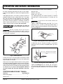
Check the oil level per the Periodic Service Schedule.
Add oil if the level on the dipstick indicates that oil is in
the add oil range (Ref. Fig. 19 on page 16).
Page 8
Do not overfill engine. Too much oil
may cause smoking or allow oil to enter
the air filter enclosure.
Both the oil dipstick and fill cap must be in
place before operating the engine. Failure to
install the dipstick and fill cap will result in oil becoming contaminated and/or being discharged into the engine compartment.
The oil should be changed in accordance with the Periodic Service Schedule while the engine is warm. See
SERVICE AND MAINTENANCE for checking oil level
and changing oil procedures.
Maximum oil level
DO NOT OVERFILL
Add
oil
Safe
operating range
Full
Ref Dsk 1
Fig. 11 Check Oil Level on Dipstick
COLD STARTING
Starting a cold engine may require use of the choke.
Depress the accelerator approximately 1" (2.5 cm) or
until the starter just begins to operate. Pull the choke out
if required. Accelerate slowly and push the choke in completely when the engine runs smoothly.
Do not allow the starter to operate continuously for more than 10 seconds.
Allow 30 seconds between starting attempts. If the vehicle does
not start on the third attempt, turn the key switch off, set the park
brake and determine the cause of the problem.
If the vehicle had been running and the engine does not
start within 10 seconds, use the choke.
STARTING AND DRIVING
To reduce the possibility
of roll-back which could
result in severe injury or
vehicle damage, do not release service brake until
engine has started.
!
!
To operate vehicle:
• Apply the service brake, place the key in the key
switch and turn it to the ‘ON’ position.
• Move the direction selector to the direction
desired.
Owner’s Manual and Service Guide
OPERATION AND SERVICE INFORMATION
Read all of manual to become thoroughly familiar with this vehicle. Pay particular attention to all Notes, Cautions and Warnings
• Release the park brake by depressing the service
•
•
brake pedal until the park brake releases.
Slowly depress the accelerator pedal to start the
engine. Release service brake when engine
starts.
When the accelerator pedal is released, the ignition circuit is de-energized and the engine stops.
To stop the vehicle more quickly, depress the service brake pedal.
When the direction selector is in the reverse
position, a warning signal will sound to indicate
that the vehicle is ready to run in reverse.
STARTING THE VEHICLE ON A HILL
To reduce the possibility
!
! of roll-back which could
result in severe injury or
vehicle damage, do not release service brake until
engine has started.
Do not hold vehicle on hill by using
accelerator and engine. This will cause
premature and excessive wear to drive train components.
To reduce the possibility of permanent damage to the
drive system, it is important to prevent excessive rollback when starting the vehicle on a hill.
Do not smoke near the fuel tank.
Do not refuel near open flame or electrical items
which could produce a spark.
Always handle gasoline in a well ventilated area.
Always wear eye protection to protect against
splashed fuel and fuel vapors.
Always allow adequate space for the expansion of
gasoline. Leave at least 1" (2.5 cm) space below
bottom of filler neck.
Inspect fuel cap, tank and other components for
leaks or deterioration that could cause a hazardous condition.
The fuel tank is located under the seat on the passenger
side of the vehicle (Ref. Fig. 12 on page 9). Fill the tank
with fresh, clean, automotive grade gasoline (Ref. Fig. 39
on page 26). High altitude or heavy use/load applications
may benefit from higher octane gasoline.
Do not use gasoline which contains Methanol.
Some fuels, called oxygenated or reformulated gasoline, are gasoline blended with
alcohols or ethers. Excessive amounts of these blends can damage the
fuel system or cause performance problems. If any undesirable operating symptoms occur, use gasoline with a lower percentage of alcohol or
ether.
Place left foot on service brake and release the park
brake. Depress accelerator with right foot and release
the service brake by lifting left foot.
COASTING
To reduce the possibility
of severe injury or death
from coasting at above
recommended speeds, limit speed with service brake.
!
On steep hills, it is possible for the vehicle to coast at
greater than normal speeds encountered on a flat surface. To reduce the possible loss of vehicle control and
severe drivetrain damage, speeds should be limited to no
more than the maximum governed speed on level ground
(see GENERAL SPECIFICATIONS). Limit speed by
applying service brake.
FUEL
!
dling:
Fuel
!
!
To reduce the possibility
of severe injury or death
from improper fuel han-
1" Min.
(2.5 cm)
Ref Ftl 1
Fig. 12 Fueling
BATTERY
Excessive use of accessories may drain
the battery and leave insufficient
reserve to start the vehicle.
The vehicle uses a combination starter/generator to both
start the engine and charge the battery. The engine will
not idle; therefore, the battery cannot be charged while
the vehicle is stopped. Do not operate accessory items
Owner’s Manual and Service Guide
Page 9
OPERATION AND SERVICE INFORMATION
Read all of manual to become thoroughly familiar with this vehicle. Pay particular attention to all Notes, Cautions and Warnings
(such as accessory lights, radios, winch, etc.) excessively while the vehicle is stopped.
The generator is capable of supplying 35 amps; therefore, operation of all accessories could result in the discharge of the battery even though the engine is running
and the generator operating. Discharging the battery is
known as deep cycling. The battery is not a deep cycle
model, but is a starting battery. Multiple deep cycling will
result in the premature failure of the battery.
OFF ON
Ref Pow 1
If the vehicle battery has become discharged, it must be
charged using a 12 volt charger that is rated at 10 amps
or less and in accordance with all instructions provided
by the manufacturer of the charger.
LABELS AND PICTOGRAMS
Vehicles may be labeled with pictograms as a method of
conveying information or warnings. Appendix A illustrates and explains pictograms that may appear on the
vehicle. Not all pictograms shown in Appendix A will be
found on your vehicle.
SUN TOP AND WINDSHIELD
The sun top does not
!
! provide protection from
roll over or falling
objects.
The windshield does not provide protection from tree
limbs or flying objects.
To prevent damage to the vehicle, do
not hold on to sun top struts and stand
on body panels.
The sun top and windshield provide some protection
from the elements; however, they will not keep the operator and passenger dry in a downpour. This vehicle is not
equipped with seat belts and the sun top has not been
designed to provide roll over protection. In addition, the
sun top does not protect against falling objects nor does
the windshield protect against flying objects and tree
limbs. Keep arms and legs inside of vehicle while it is
moving.
12 VOLT POWER OUTLET
Overuse of accessories may drain the
battery and leave insufficient reserve to
start the vehicle.
A 12 volt power outlet, rated at 15 amps, is located to the
left side of the key/light switch (Ref. Fig. 13 on page 10).
It provides constant power for accessories equipped with
Page 10
F
E
FUEL
12V Power
Outlet
Fig. 13 12 Volt Power Outlet
TOWING A TRAILER
The vehicle is equipped with a receiver that can be fitted
with a standard 1 7/8" ball. The trailer and its load must
not exceed 500 lbs (227 kg) and no more than 50 lbs (23
kg) tongue weight may be attached to the hitch. Remember that the overall capacity of the vehicle, operator, passenger, contents of load bed and accessories must be
reduced to compensate for the trailer and load.
The range of motion of the trailer is limited by the ball and
hitch. The trailer should not be used on rough trails or
over objects such as logs, large rocks, holes, etc.
Never install baskets or extensions using the hitch
receivers (front or rear). Such items will change the performance characteristics of vehicle and result in unsafe
handling, possible roll over or vehicle damage.
VEHICLE CLEANING AND CARE
VEHICLE CLEANING
To reduce the possibility
of severe injury or vehicle damage, read and
understand all instructions supplied by manufacturer
of pressure washer.
!
!
When pressure washing exterior of
vehicle, do not use pressure in excess
of 700 psi. To reduce the possibility of cosmetic damage, do not
use any abrasive or reactive solvents to clean plastic parts.
It is important that proper techniques and cleaning materials be used. Using excessive water pressure may
cause severe injury to operator or bystander, damage to
seals, plastics, seat material, body finish or electrical system. Do not use pressure in excess of 700 psi to wash
exterior of vehicle.
Clean windshield with lots of water and a clean cloth.
Minor scratches may be removed using a commercial
Owner’s Manual and Service Guide
OPERATION AND SERVICE INFORMATION
Read all of manual to become thoroughly familiar with this vehicle. Pay particular attention to all Notes, Cautions and Warnings
plastic polish or Plexus® plastic cleaner available from
the service parts department.
Normal cleaning of vinyl seats and plastic or rubber trim
requires the use of a mild soap solution applied with a
sponge or soft brush and wipe with a damp cloth.
Always place chocks in front and behind the
wheels not being raised.
Use extreme care since the vehicle is extremely
unstable during the lifting process.
When lifting vehicle, position jacks and
jack stands at the areas indicated only.
Removal of oil, tar, asphalt, shoe polish, etc. will require
the use of a commercially available vinyl/rubber cleaner.
The painted surfaces of the vehicle provide attractive
appearance and durable protection. Frequent washing
with lukewarm or cold water and mild detergent is
required to preserve the painted surfaces.
Occasional cleaning and waxing with non-abrasive products designed for ‘clear coat’ automotive finishes will
enhance the appearance and durability of the painted
surfaces.
Corrosive materials used as fertilizers or for dust control
can collect on the underbody of the vehicle. These materials will cause corrosion of underbody parts unless
flushed occasionally with plain water. Thoroughly clean
any areas where mud or other debris can collect. Sediment packed in closed areas should be loosened to ease
it’s removal, taking care not to chip or otherwise damage
paint.
To raise the entire vehicle, install chocks in front and
behind each front wheel (Ref. Fig. 14 on page 11). Center the jack under the rear frame crossmember. Raise the
vehicle enough to place a jack stand under the outer
ends of the rear axle.
Lower the jack and test the stability of the vehicle on the
two jack stands.
Place the jack at the center of the front axle. Raise the
vehicle enough to place jack stands under the frame
crossmember as indicated.
Lower the jack and test the stability of the vehicle on all
four jack stands.
If only the front or rear of the vehicle is to be raised, place
the chocks in front and behind each wheel not being
raised to stabilize the vehicle.
Lower the vehicle by reversing the lifting sequence.
If the engine does not start or runs improperly
after washing, remove the spark plug wires (by
pulling the spark plug boots, never the wires). Dry all connections with forced air. Reinstall the wires.
Center of
Front Axle
REPAIR
LIFTING THE VEHICLE
Tool List
Qty. Required
Floor jack .................................................................... 1
Jack stands ................................................................. 4
Chocks ........................................................................ 4
Some servicing operations may require the front wheels,
the rear wheels, or the entire vehicle be raised.
!
!
Flat Portion
of Frame
To reduce the possibility
of severe injury or death
from a vehicle falling
from a jack:
Be sure the vehicle is on a firm and level surface.
Never get under a vehicle while it is supported by
a jack.
Use jack stands and test the stability of the vehicle on the stands.
Outside End
of Rear Axle
Ref Liv 1
View from Underside of Vehicle
Fig. 14 Lifting the Vehicle
Owner’s Manual and Service Guide
Page 11
OPERATION AND SERVICE INFORMATION
Read all of manual to become thoroughly familiar with this vehicle. Pay particular attention to all Notes, Cautions and Warnings
The vehicle is fitted with low pressure tubeless tires
mounted on one piece rims; therefore, the most cost
effective way to repair a puncture in the tread is to use a
commercial tire plug.
WHEELS AND TIRES
Tire Repair
Tool List
Qty. Required
Lug wrench, 3/4" ......................................................... 1
Impact socket, 3/4", 1/2" drive ..................................... 1
Impact wrench, 1/2" drive ............................................ 1
Torque wrench, 1/2" drive............................................ 1
A tire explosion can
cause severe injury or
death. Never exceed
inflation pressure rating on tire sidewall.
To reduce the possibility of tire explosion, pressurize tire with small amount of air applied intermittently to seat beads. Due to the low volume of
the small tires, overinflation can occur in seconds. Never exceed the tire manufacturer’s recommendation when seating a bead. Protect face
and eyes from escaping air when removing valve
core.
To reduce the possibility of severe injury caused
by a broken socket when removing wheels, use
only sockets designed for impact wrench use.
Use caution when inflating tires. Overinflation
could cause the tire to separate from the wheel or
cause the tire to explode, either of which could
cause severe injury.
!
!
Use caution when inflating tires. Due to the low volume of
the small tires, overinflation can occur in seconds. Overinflation could cause the tire to separate from the wheel
or cause the tire to explode.
Tire inflation should be determined by the condition of the
terrain. See GENERAL SPECIFICATIONS section for
recommended tire inflation pressure. For outdoor applications with major use on grassy areas, the following
should be considered. On hard turf, it is desirable to have
a slightly higher inflation pressure. On very soft turf, a
lower pressure reduces the possibility of tires cutting into
the turf. For vehicles being used on paved or hard surfaces, tire inflation pressure should be in the higher
allowable range, but under no condition should inflation
pressure be higher than recommended on tire sidewall.
All four tires should have the same pressure for optimum handling characteristics. Be sure to install the valve
dust cap after checking or inflating.
Page 12
Tire plug tools and plugs are available at most
automotive parts outlets and have the advantage of not requiring the tire be removed from the wheel.
If the tire is flat, remove the wheel and inflate the tire to
the maximum recommended pressure for the tire.
Immerse the tire in water to locate the leak and mark with
chalk. Insert tire plug in accordance with manufacturer’s
instructions.
To reduce the possibility
of severe injury, be sure
mounting/demounting
machine is anchored to floor. Wear OSHA approved
safety equipment when mounting/demounting tires.
!
!
If the tire is to be removed or mounted, the tire changing
machine manufacturer’s recommendations must be followed in order to reduce possibility of severe injury.
Wheel Installation
To reduce the possibility of component
damage, do not tighten lug nuts to more
than 85 ft. lbs. (115 Nm) torque.
It is important to follow the ‘cross sequence’
pattern when installing lug nuts. This will
assure even seating of the wheel against the hub.
With the valve stem to the outside, mount the wheel onto
the hub with lug nuts. Finger tighten lug nuts in a ‘cross
sequence’ pattern (Ref. Fig. 15 on page 12) . Tighten lug
nuts to 50 - 85 ft. lbs. (70 - 115 Nm) torque in 20 ft. lbs.
(30 Nm) increments following the ‘cross sequence’ pattern.
'Cross Sequence'
3
1
Tire style
may vary
4
Ref Whi 1
Fig. 15 Wheel Installation
Owner’s Manual and Service Guide
2
OPERATION AND SERVICE INFORMATION
Read all of manual to become thoroughly familiar with this vehicle. Pay particular attention to all Notes, Cautions and Warnings
LIGHT BULB REPLACEMENT
Roll Rubber
Bezel Away
From Body
To reduce the possibility of premature
bulb failure, do not touch new bulbs
with bare fingers. Use clean, dry tissue or paper towel to handle
the glass portion of the bulb.
Tail/Brake
Light
For vehicles with headlights mounted in cowl, locate the
two screws on backside of cowl that secure headlight
(Ref. Fig. 16 on page 13). Remove screws, pull headlight
out and disconnect wires. Connect wires to new headlight, install in cowl and secure with screws previously
removed.
Turn Signal Lens
Inside
of Cowl
Rear
Fender
Ref Tlr 2
Fig. 17 Tail and Brake Light Bulb Replacement
erator functions as a starter and with the engine running,
it functions as a generator.
Headlight
Bulb
Turn Signal
Housing
Ref Hdr 2
Fig. 16 Headlight and Turn Signal Bulb Replacement
To replace the turn signal light bulb, support turn signal
housing from backside of cowl while removing two
screws securing lens. Install new bulb and replace lens.
To replace the tail and brake light bulb, roll the rubber
bezel from around the edge of the taillight and remove
lens. Install replacement bulb and replace lens.
With the short running times associated with this kind of
vehicle, the generator is more than adequate to maintain
the battery charge level. The generator is not designed to
charge a discharged battery.
When engine starts, the clutches engage and cause
vehicle to move making ‘jump starting’ both dangerous
and impractical.
If the vehicle battery has become discharged, it must be
charged using a 12 volt charger that is rated at 10 amps
or less. Read and understand all instructions provided by
the manufacturer of the charger.
FUSE REPLACEMENT
To replace fuses, locate the fuse block under the driver
side seat. Pull out old fuse and replace with a new automotive type fuse. Headlight and taillight bulbs and fuses
are available from a local Distributor, an authorized
Branch or the Service Parts Department.
VEHICLE WITH A DISCHARGED BATTERY
To reduce the possibility
of severe injury or death
from inadvertent motion,
do not attempt to ‘jump start’ a vehicle.
!
!
The vehicle is equipped with a starter/generator and
does not idle. When starting the engine, the starter/gen-
Owner’s Manual and Service Guide
Page 13
OPERATION AND SERVICE INFORMATION
Read all of manual to become thoroughly familiar with this vehicle. Pay particular attention to all Notes, Cautions and Warnings
TRANSPORTING VEHICLE
TOWING
!
!
This vehicle is not
designed to be towed.
It is recommended that the vehicle be moved by placing
the entire vehicle on a trailer, flatbed truck or other suitable transport.
NEUTRAL LOCK
To prevent the driven clutch from turning the rear wheels
during service operations, a neutral lock is located on the
direction selector.
To operate:
Turn key switch to ‘OFF’ and lift seat. Pull out and rotate
the neutral lock pin handle so that the pointed portion of
the handle is to the side of the direction selector cam
(Ref. Fig. 18 on page 14). Move direction selector
towards the area between ‘F’ and ‘R’. During that motion,
the pin will snap into the hole in the direction selector
mounting bracket preventing any movement. When in
this position, the direction selector remains locked in the
neutral position. To unlock the direction selector, pull the
neutral lock pin handle out and rotate until the pointed
portion of the handle fits into the hole in the direction
selector cam.
Hole in Direction
Selector Cam
HAULING
!
To reduce the possibility
of severe injury or death
while transporting vehicle:
Secure the vehicle and contents.
Never ride on vehicle being transported.
Always remove windshield before transporting.
Maximum speed with sun top installed is 50 mph
(80 kph).
If the vehicle is to be transported at highway speeds, the
sun top must be removed and the seat bottom secured.
When transporting vehicle below highway speeds, check
for tightness of hardware and cracks in sun top at mounting points. Always remove windshield when transporting.
Always check that the vehicle and contents are adequately secured before transporting. The rated capacity
of the trailer or truck must exceed the weight of the vehicle (see GENERAL SPECIFICATIONS for vehicle
weight) and load. Lock the park brake and secure the
vehicle using ratchet tie downs.
Hole in Direction
Selector Mounting
Bracket
To
Lock
Unlocked
2
1
Neutral Lock
Pin Handle
Ref Nlk 2
Fig. 18 Neutral Lock
Page 14
!
Owner’s Manual and Service Guide
OPERATION AND SERVICE INFORMATION
Read all of manual to become thoroughly familiar with this vehicle. Pay particular attention to all Notes, Cautions and Warnings
SERVICE AND MAINTENANCE
!
!
To reduce the possibility
of severe injury or death
from improper servicing
techniques:
Do not attempt any type of servicing operations
before reading and understanding all notes, cautions and warnings in this manual.
Any servicing requiring adjustments to be made
to the powertrain while the engine is running
must be made with both drive wheels raised and
vehicle properly supported on jack stands.
To reduce the possibility of engine damage, never
operate vehicle at full throttle for more than 4 - 5
seconds while vehicle is in a ‘no load’ condition.
Wear eye protection when working on
the vehicle. Use extra care when working around batteries, or using solvents or compressed air.
To reduce the possibility of causing an electrical
arc, which could result in a battery explosion, turn
off all electrical loads from the battery before
removing battery wires.
Wrap wrenches with vinyl
tape to reduce the possibility
of a dropped wrench ‘shorting out’ a battery, which could result in an explosion.
Reduce the possibility of accidental starting by
removing and grounding spark plug wires and
disconnecting battery at negative terminal before
servicing.
The electrolyte in a battery is an acid solution
which can cause severe burns to the skin and
eyes. Treat all electrolyte spills to the body and
eyes with extended flushing with clear water.
Contact a physician immediately.
Any electrolyte spills should be neutralized with a
solution of 2 teaspoons (10 ml) sodium bicarbonate (baking soda) dissolved in 1 quart (1 liters) of
water and flushed with water.
Aerosol containers of battery terminal protectant
must be used with extreme care. Insulate metal
container to reduce the possibility of can contacting battery terminals which could result in an
explosion.
It is in the best interest of both vehicle owner and service
technician, to carefully follow the procedures recommended in this manual. Preventative maintenance,
applied at recommended intervals, is the best guarantee
for keeping the vehicle both dependable and economical.
This vehicle will give years of satisfactory service, providing it receives regular maintenance. Refer to the Periodic
Service Schedule for appropriate service intervals (Ref.
Fig. 19 on page 16). Refer to Lubrication Points for
appropriate lubrication locations (Ref. Fig. 37 on page
24).
To prolong vehicle life, some maintenance items must be serviced more frequently on vehicles used under severe driving conditions such
as extreme temperatures, extreme dust/debris conditions, frequent use with maximum load.
To access powertrain for routine maintenance, lift or
remove seat. For major repair, refer to appropriate Technician’s Repair and Service Manual.
Some service procedures may require the vehicle to be
lifted. Refer to LIFTING THE VEHICLE for proper lifting
procedure and safety information.
SERIAL NUMBER LABEL LOCATION
Two serial number and manufacture date code label are
on the vehicle. One is placed on the body below the
front, driver side of the seat. The other is located on the
chassis under the seat.
Design changes take place on an ongoing basis. In order
to obtain correct components for the vehicle, the manufacture date code, serial number and vehicle model must
be provided when ordering service parts.
Owner’s Manual and Service Guide
Page 15
OPERATION AND SERVICE INFORMATION
Read all of manual to become thoroughly familiar with this vehicle. Pay particular attention to all Notes, Cautions and Warnings
PERIODIC SERVICE SCHEDULE
✓ Check
♦ Clean, Adjust, etc.
▲ Replace
To perform service that is listed in this schedule but not described in this manual, contact a local Service Representative or see the Repair and Service Manual for this vehicle.
NOTE: Some maintenance items must be serviced more frequently on vehicles used under severe driving conditions
DAILY
BEFORE USE:
✓ Check service brake general operation
✓ Check park brake function
✓ Check warning device function in reverse
✓ Check tire condition
✓ Check overall vehicle condition
WEEKLY
TIRES
✓ Examine for cuts, excessive wear and pressure (See GENERAL SPECIFICATIONS)
WHEELS
✓ Check for bent rims, missing or loose lug nuts
FUEL GAUGE
✓ Check for proper operation (at fueling), and fuel cap vent is free of dirt
ENGINE OIL
✓ Check and add if required - DO NOT OVERFILL
STARTER/GENERATOR BELT
✓ Check for tension, wear, cracks
MONTHLY - 20 HOURS (includes items listed in previous table & the following)
WIRING
✓ Check all wiring for loose connections and broken/missing insulation
ACCELERATOR
✓ Check for smooth movement - DO NOT LUBRICATE CABLE
SERVICE BRAKE
(MECHANICAL BRAKES)
✓ Conduct brake performance test
PARK BRAKE
✓ Check brake performance and adjust if required
CHOKE CABLE
✓ Check for smooth movement and adjustment - DO NOT LUBRICATE CABLE
CARBURETOR LINKAGE
✓ Check attachment, adjust as required
DIRECTION SELECTOR
✓ Check attachment, adjust as required
ENGINE
✓ Check for unusual noise, vibration, acceleration, oil leaks
COOLING FAN
✓ Check for build-up of foreign matter inside blower housing and fins, clean if required
STEERING ASSEMBLY
✓ Check for abnormal play, tightness of all hardware
TIE ROD/LINKAGES
✓ Check for excessive play, bent components or loose connections
REAR AXLE
✓ Check for leakage, add SAE 30 oil as required
QUARTERLY - 50 HOURS (includes items listed in previous tables & the following)
FRONT AXLE
✓ Check for damage to axle and loose or missing hardware
Fig. 19 Periodic Service Schedule
Page 16
Owner’s Manual and Service Guide
OPERATION AND SERVICE INFORMATION
Read all of manual to become thoroughly familiar with this vehicle. Pay particular attention to all Notes, Cautions and Warnings
FRONT SHOCK ABSORBERS
✓ Check for oil leakage and loose fasteners
FRONT SPRINGS
✓ Check for loose hardware, cracks at attachments
FRONT WHEEL ALIGNMENT
✓ Check for unusual tire wear, align if required
PARK BRAKE
✓ Check for bent/binding linkage rod
✓ Check for damage or wear to latch arm or catch bracket
♦ Lubricate as required, use light oil. DO NOT LUBRICATE CABLES OR BRAKE
LATCH
REAR SHOCK ABSORBERS
✓ Check for oil leakage, loose mounting hardware
ENGINE ELECTRICAL SYSTEM
✓ Check coil/spark plug wires for cracks/loose connections
FUEL SYSTEM
✓ Check for leaks at tank, cap, system lines, filters, pump, carburetor
✓ Check system lines for cracks/deterioration
THROTTLE/GOVERNOR LINKAGE
✓ Check operation and governed speed
HARDWARE AND FASTENERS
✓ Check for loose or missing hardware and components
♦ Tighten or replace missing hardware
SEMI-ANNUAL - 125 HOURS (includes items listed in previous tables & the following)
BATTERY
♦ Clean battery & terminals
DIRECTION SELECTOR
✓ Check for wear and smooth movement (lubricate shaft with light oil if required)
KING PINS
✓ Check for excessive play and tightness of retaining nuts
STEERING ASSEMBLY
✓ Check bellows and pinion seal for damage or grease leakage
RACK END BALL JOINT
♦ Lubricate, use wheel bearing grease
REAR AXLE
✓ Check for unusual noise and loose or missing mounting hardware
AIR FILTER ELEMENT
✓ Check filter element, clean/replace as required
OIL FILTER
♦
ENGINE OIL
▲ Replace with SAE 10W-30 or 10W-40 that meets or exceeds SF, SG, CC oil,
DO NOT OVERFILL
DRIVE BELT
✓ Check for cracks, fraying and excessive wear
Clean in solvent (at oil change), replace ‘O’ rings if required
ANNUAL - 250-300 HOURS (includes items listed in previous tables & the following)
FRONT WHEEL BEARINGS
✓ Check and adjust as required, see Technician’s Repair and Service Manual
REAR AXLE
✓ Check lubricant, add lubricant (Ref. Fig. 39 on page 26) as required
SERVICE BRAKES
♦ Clean and adjust, see Technician’s Repair and Service Manual
✓ Check brake shoe linings, see Technician’s Repair and Service Manual
✓ Check level, add if required (DOT 3) and check for leakage
FUEL FILTER
▲ Replace
SPARK PLUGS
▲ Replace, gap new plugs (Ref. Capacities and Replacement Parts on page 26)
MUFFLER/EXHAUST
✓
Check mounting hardware; check for leaks at head and muffler gaskets
VALVES
✓
Check cold (intake/exhaust) per Technician’s Repair and Service Manual
Fig. 19 Periodic Service Schedule
Owner’s Manual and Service Guide
Page 17
OPERATION AND SERVICE INFORMATION
Read all of manual to become thoroughly familiar with this vehicle. Pay particular attention to all Notes, Cautions and Warnings
500 HOURS (includes items listed in previous tables & the following)
TIMING BELT
✓ Check tension and for signs of wear/damage, replace if worn or damaged
CARBURETOR
♦ Clean
CYLINDER HEAD AND PISTONS
♦ Remove carbon from cylinder head and pistons
✓ Check valve seats for carbon buildup and clean as required
Fig. 19 Periodic Service Schedule
TIRE INSPECTION
Tire condition should be inspected per the Periodic Service Schedule (Ref. Fig. 19 on page 16). Inflation pressures should be checked when the tires are cool. Be sure
to install the valve dust cap after checking or inflating.
The engine can be operated safely as long as oil is within
the safe operating range as indicated on the dipstick. Do
not operate vehicle if oil level is below the safe area
indicated on the dipstick (Ref. Fig. 21 on page 18).
Maximum oil level
DO NOT OVERFILL
CHECKING THE OIL LEVEL
Do not overfill engine. Too much oil
may cause engine to smoke or spark
plug fouling.
When adding oil between oil changes, do not
mix brands and viscosity grades of oil. Both the
oil dipstick and fill cap must be in place before operating the
engine. Failure to install the dipstick and fill cap will result in oil
becoming contaminated and/or oil being discharged into the
engine compartment.
The oil should be checked with the engine warm. The
vehicle must be on a level surface with the park brake
engaged. Allow adequate time for oil to drain into the
crankcase before checking.
Remove the dipstick and wipe off the entire area indicated with a lint free cloth (Ref. Fig. 20 on page 18).
Add
oil
Safe
operating range
Full
Ref Dsk 1
Fig. 21 Check Oil Level on Dipstick
Oil should be added to bring the level into the safe operating range. Do not overfill. Check that the oil fill cap
and dipstick are firmly in place.
CHANGING THE OIL
Tool List
Qty. Required
Socket, 10 mm, 3/8" drive............................................1
Ratchet, 3/8" drive .......................................................1
Extension, 8", 3/8" drive ..............................................1
Oil drain pan ................................................................1
For maximum performance and longevity, the engine oil
should be replaced every 125 hours of operation or semiannually, whichever comes first.
F
The selection of oil is dependent upon the service that
the vehicle will perform. Most vehicles require 10W-30
oil, whereas vehicles used at capacity or near capacity
load applications will require 10W-40 oil after run-in (Ref.
Fig. 22 on page 19).
Ref Ced 1
Fig. 20 Clean Entire Dipstick
Insert the dipstick fully into the dipstick hole and remove.
Examine the level of oil on the dipstick.
Page 18
To reduce the possibility
of severe injury, wear
rubber gloves to protect
skin from exposure to hot, used oil and degreaser.
These fluids contain chemicals known to cause cancer.
!
Owner’s Manual and Service Guide
!
OPERATION AND SERVICE INFORMATION
Read all of manual to become thoroughly familiar with this vehicle. Pay particular attention to all Notes, Cautions and Warnings
Large
'O' Ring
HEAVY DUTY WORK
10W-40
10W-30
LIGHT DUTY WORK
Ref Rof 1
10W-30
Oil
Filter
Small 'O' Ring Inside
End Of Oil Filter
Fig. 24 Remove Oil Filter
F
0
-20
C 0 -30
Ref Ovc 1
0
-20
20
40
60
80
-10
0
10
20
(AIR TEMPERATURE)
Wear eye protection to reduce the possibility of splashed solvent contacting the
eyes when cleaning oil filter.
100
30
40
Fig. 22 Oil Viscosity Chart
The oil should be changed with the engine warm. Park the vehicle on a level surface, engage the park brake and remove the
key. Place a drain pan under the engine. Wipe the top of the
engine clean with a cloth (Ref. Fig. 23 on page 19). Remove the
oil fill cap.
Clean the filter by washing in any shop degreaser and
brushing the metal screen clean with a soft brush (Ref.
Fig. 25 on page 19).
Ref Cof 1
Oil Fill Cap
Fig. 25 Clean Oil Filter
Blow out the filter with low pressure air 30 psi (210 kPa)
or less from no closer than 3" (8 cm) and allow to air dry
(Ref. Fig. 26 on page 19).
Ref Cte 1
Fig. 23 Clean Top of Engine
Clean the area around the filter. Oil drainage is accomplished by removing the three bolts securing the oil filter
to the engine. Remove the filter by pulling it from the
engine and allow the oil to drain. The ‘O’ rings may
remain on the engine or the filter (Ref. Fig. 24 on page
19).
At each oil change, thoroughly inspect filter before cleaning. At the first oil change, metal chips and lint may be
found. This is normal, resulting from engine run-in. At
subsequent oil changes, the presence of metal chips
may indicate possible engine damage.
3" (8 cm)
Minimum
Ref Bof 1
30 psi (210 kPa) Maximum
Fig. 26 Blowing Out Oil Filter
Wipe the area around the filter mount with a clean, lint
free cloth and inspect both filter ‘O’ rings for damage;
replace if necessary. Install the filter into the engine. The
filter engages over a short nipple in the engine. The filter
should slide easily onto the nipple and seat against the
engine using light hand pressure only. Align the holes in
Owner’s Manual and Service Guide
Page 19
OPERATION AND SERVICE INFORMATION
Read all of manual to become thoroughly familiar with this vehicle. Pay particular attention to all Notes, Cautions and Warnings
the filter mounting plate with the holes in the engine.
Install and hand tighten the bolts before tightening them
firmly.
Wrench, 9/16" ..............................................................2
Ratchet, 3/8" drive .......................................................1
Socket, 3/4", 3/8" drive ................................................1
Add slightly less than 1 1/2 quarts (1.4 liters) to allow for
possible residual oil left in engine (Ref. Fig. 27 on page
20). The oil must be high quality oil that meets or
exceeds API SF, SG, CC standards (Ref. Fig. 39 on page
26). Check oil level on dipstick. If necessary, continue to
add oil slowly and allow time for oil to flow down into
engine. Check oil level on dipstick. Do not overfill.
The starter/generator belt tension should be checked
after the first 15 - 20 hours and set to 75 - 80 lbs. (34 - 36
kg).
Do not overfill engine. Too much oil
may cause smoking or allow oil to enter
the air filter enclosure.
A loose belt can cause audible vibration and
squeal.
Tighten a new starter/generator belt (Ref. Fig. 39 on
page 26) to 90 - 110 lbs. (41-50 kg) tension when a
gauge is applied half way between the two pulleys (Ref.
Fig. 28 on page 20).
Both the oil dipstick and fill cap must be in
place before operating the engine. Failure to
install the dipstick and fill cap will result in oil being discharged
into the engine compartment.
Ref Cbg 1
Fig. 28 Checking Belt Tension with Gauge
'O' Ring
A new belt may be checked manually. A maximum
deflection of 3/8" (10 mm) is acceptable (Ref. Fig. 29 on
page 20).
3/8" (1 cm) Max. Deflection for New Belt
1/2" (1.3 cm) Max. Deflection for Existing
Belt
Ref Aeo 1
Fig. 27 Add Engine Oil
Inspect oil fill cap ‘O’ ring and replace if necessary. Install
the oil fill cap. Run the vehicle for one or two minutes and
check the filter for oil leaks.
Check the oil level again with the vehicle on level ground.
Oil should be added to bring the level into the safe operating range. Do not overfill. The engine can be operated
safely as long as the oil is within the safe operating range
as indicated on the dipstick. Do not operate vehicle if
oil level is below the safe area indicated on the dipstick.
Ref Cbm 1
Fig. 29 Checking Belt Tension Manually
Tighten an existing belt to 75 - 80 lbs. (34 - 36 kg) tension using the same technique and inspect for cracking
or wear. A maximum deflection of 1/2" (13 mm) is acceptable.
STARTER/GENERATOR BELT TENSION
Tool List
Qty. Required
Belt tension gauge....................................................... 1
Wrench, 3/4"................................................................ 1
Page 20
Owner’s Manual and Service Guide
OPERATION AND SERVICE INFORMATION
Read all of manual to become thoroughly familiar with this vehicle. Pay particular attention to all Notes, Cautions and Warnings
Adjusting the Belt
Loosen the starter/generator pivot bolt.
While holding the lower adjusting nut with a wrench,
loosen the upper jam nut with another wrench. Move the
lower nut up or down the adjustment bolt until proper belt
tension is achieved. Hold the lower nut in place and
tighten the upper jam nut against it (Ref. Fig. 30 on page
21).
injury or death, do not use metallic spray wand to
clean battery and keep all smoking materials, open
flame or sparks away from the battery.
The correct cleaning technique is to spray the top and
sides of the battery with a solution of sodium bicarbonate
(baking soda) and water. This solution is best applied
with a garden type sprayer equipped with a non metallic
spray wand or a plastic spray bottle. The solution
should consist of the amounts of sodium bicarbonate
(baking soda) and clear water shown below (Ref. Fig. 31
on page 21). In addition to the battery, special attention
should be paid to metal components adjacent to the battery which should also be sprayed with the sodium bicarbonate (baking soda) solution.
Jam Nut
1 1/2 gallons
(6 liters)
Clear Water
Adjusting Nut
Ref Abt 1
Fig. 30 Adjusting Belt Tension
1 quart
(1 liter)
Clear Water
1/4 Cup (60 ml)
Sodium Bicarbonate
(Baking Soda)
Tighten the starter/generator pivot bolt.
OR
Non
Metallic
Wand
BATTERY CLEANING
To reduce the possibility of damage to
vehicle or floor, neutralize acid before
rinsing battery.
To reduce the possibility of damage to electrical components
while cleaning, do not use a pressure washer.
2 Teaspoons
(10 ml)
Sodium
Bicarbonate
(Baking Soda)
Plastic
Spray
Bottle
2 Gallon
(7.5 liter)
Garden
Sprayer
Ref Pns 1
Cleaning should take place per the Periodic Service
Schedule (Ref. Fig. 19 on page 16).
When cleaning the outside of the battery and terminals,
first spray with a solution of sodium bicarbonate (baking
soda) and water to neutralize any acid deposits before
rinsing with clear water.
Use of a water hose without first neutralizing any acid,
will move acid from the top of the battery to another area
of the vehicle or storage facility where it will attack the
metal structure or the concrete/asphalt floor. Additionally,
a residue will be left on the battery which is conductive
and will contribute to the discharge of the battery.
!
!
To reduce the possibility
of battery explosion that
could result in severe
Fig. 31 Preparing Acid Neutralizing Solution
Allow the solution to sit for at least three minutes; use a
soft bristle brush or cloth to wipe the tops of the battery to
remove any residue that could contribute to the self discharge of the battery. Rinse the entire area with low pressure clear water. Do not use a pressure washer.
BRAKES
To reduce the possibility
of severe injury or death,
always evaluate pedal
travel before operating a vehicle to verify some braking function is present.
All driving brake tests must be done in a safe location
with regard for the safety of all personnel.
!
Owner’s Manual and Service Guide
!
Page 21
OPERATION AND SERVICE INFORMATION
Read all of manual to become thoroughly familiar with this vehicle. Pay particular attention to all Notes, Cautions and Warnings
Periodic Brake Test for Mechanical Brakes
The purpose of this test is to compare the braking performance of the vehicle to the braking performance of new
or ‘known to be good’ vehicles or to an established
acceptable stopping distance. Actual stopping distances
will be influenced by weather conditions, terrain, road
surface condition, actual vehicle weight (accessories
installed) and vehicle speed. No specific braking distance
can be reliably specified. The test is conducted by latching the parking brake to eliminate different pedal pressures and to include the affects of linkage misadjustment.
Dry, Level, Clean, Paved Surface
Establish the acceptable stopping distance by testing a
new or ‘known to be good’ vehicle and recording the
stopping location or stopping distance. For fleets of vehicles, several vehicles should be tested when new and
the range of stopping locations or distances recorded.
Accelerate To
Maximum Speed
Over time, a subtle loss of performance may
take place; therefore, it is important to establish
the standard with a new vehicle.
Latch
Parking Brake
and Take Foot
Off Pedal
Acceptable
Stopping 4 ft. (1.2 m)
Distance
Ref Bpt 1
Line or Marker
Line or Marker
Normal Range of
Stopping Distance
Any vehicles that stop
more than 4 ft. (1.2 m)
beyond the Acceptable
Stopping Distance or
pulls to one side should
be removed from service
and inspected by a
qualified mechanic
Fig. 32 Typical Brake Performance Test
Over time, a subtle loss of performance may
take place; therefore, it is important to establish
the standard with a new vehicle.
The Periodic Brake Performance Test should be performed regularly (Ref. Fig. 19 on page 16) as an evaluation of braking system performance or if there is a
decrease in braking effectiveness. It is useful as a
method of identifying subtle loss of performance over
time.
Page 22
Drive the vehicle at maximum speed on a flat, dry, clean,
paved surface (Ref. Fig. 32 on page 22). Quickly depress
the brake pedal to latch the parking brake at the line or
marker in the test area and remove foot from pedal. The
vehicle should stop aggressively. The wheel brakes may
or may not lock. Observe the vehicle stopping location or
measure the vehicle stopping distance from the point at
which the brakes were latched. The vehicle should stop
within the ‘normal’ range of stopping distances. If the
vehicle stops more than 4 ft. (1.2 m) beyond the acceptable stopping distance or pulls to one side, the vehicle
has failed the test and should be tested again.
If the vehicle fails the second test, it should immediately
be removed from service. The vehicle must be inspected
by a qualified mechanic who should refer to the TROUBLESHOOTING section in the Technicain’s Repair and
Service Manual.
Hydraulic Front Disc Brakes
For vehicles equipped with hydraulic front disc brakes,
check master cylinder fluid per PERIODIC SERVICE
SCHEDULE or if there is a decrease in braking effectiveness. Inspect components for damage or wear. It is
unlikely that fluid will need to be added unless there is a
leak in the system. Raise the front of the vehicle (See
raising the vehicle). Remove passenger side wheel/tire.
Carefully wipe off dirt and debris from master cylinder
and cap before opening. Remove the cap. Using a
mechanics mirror, check to see that fluid is no more than
Owner’s Manual and Service Guide
OPERATION AND SERVICE INFORMATION
Read all of manual to become thoroughly familiar with this vehicle. Pay particular attention to all Notes, Cautions and Warnings
1/4" below top of reservoir. Add DOT 3 or 4 fluid as
required.
AIR INTAKE AND COOLING FINS
Fill Plug
To prevent possible
!
! burns, engine parts
should be kept clean to
reduce risk of overheating and ignition of accumulated debris.
Check Plug
Ref Raf 2
Drain Plug
Fig. 35 Add, Check and Drain Rear Axle Lubricant
Checking the Lubricant Level
Tool List
Qty. Required
Socket, 13 mm, 3/8" drive ........................................... 1
Ratchet, 3/8" drive ....................................................... 1
Funnel ......................................................................... 1
Ref Cai 1
Fig. 33 Cleaning Air Intake
After every off road use, allow to cool and then check for
a build up of dirt and debris in the air intake and cooling
fins. Dirt and debris may clog the engine’s air cooling
system. Clean areas shown to prevent engine damage
(Ref. Fig. 33 on page 23) (Ref. Fig. 34 on page 23). Keep
linkages, springs and controls clean. Keep area around
muffler free of any combustible material.
Clean the area around the check and fill plugs. Remove
the check plug. The correct lubricant level is just below
the bottom of the threaded hole (Ref. Fig. 39 on page
26). If lubricant is to be added, remove the fill plug and
add lubricant using a funnel. Add lubricant slowly until
lubricant starts to seep from the check plug hole. Install
the check plug and the fill plug. In the event that the lubricant is to be replaced, a drain plug is provided at the bottom of the differential housing.
AIR CLEANER INSPECTION AND REPLACEMENT
Canister Type Air Cleaner
The air cleaner element is accessible by unsnapping the
clips on the air canister and removing the cover and air
filter element (Ref. Fig. 36 on page 24). Clean inside of
cover, canister and dust collector. Install the element and
cover the same way they were removed. Be sure the
positioning arrow on cover is pointing upward and all
clips are fastened securely.
Ref Ccf 1
Cleaning the Air Filter Element
Fig. 34 Cleaning the Cooling Fins
REAR AXLE
The rear axle is provided with a lubricant level check plug
located on the driver side at the rear of the housing (Ref.
Fig. 35 on page 23). Unless leakage of rear axle lubricant
is evident, an annual lubricant check is sufficient.
Do not use compressed air to clean the
air filter; doing so will damage the filter
which may result in damage to the engine.
If the element is in acceptable condition, loose dirt may
be removed by tapping the filter lightly. Do not use oil on
the filter element or any part of the unit. Install the ele-
Owner’s Manual and Service Guide
Page 23
OPERATION AND SERVICE INFORMATION
Read all of manual to become thoroughly familiar with this vehicle. Pay particular attention to all Notes, Cautions and Warnings
Air Cleaner
Canister
Remove and inspect the spark plugs at intervals indicated in the Periodic Service Schedule (Ref. Fig. 19 on
page 16). All new spark plugs should be properly gapped
before installation (Ref. Fig. 39 on page 26). Apply a light
coat of anti-seize compound and tighten to 18 ft. lbs. (24
Nm) torque.
Air Filter
Element
Air Cleaner
Cover
Dust
Collector
Ref Air 2
Fig. 36 Canister Type Air Cleaner
ment in the same way it was removed, being sure that
the clips are fastened securely.
LUBRICATION
Do not use more than three (3) pumps
of grease in any grease fitting at any
one time. Excess grease may cause grease seals to fail or
grease migration into areas that could damage components.
Putting more than three pumps of grease in a grease fitting could damage grease seals and cause premature
bearing failure (Ref. Fig. 37 on page 24).
Rack Ball Joint
Ref Lub 1
View From Underside Of Vehicle
Fig. 37 Lubrication Points
SPARK PLUGS
Tool List
Qty. Required
Spark plug socket, 13/16", 1/2" drive........................... 1
Ratchet, 1/2" drive ....................................................... 1
Plug gauge, wire type.................................................. 1
Anti-seize compound................................................ AR
Torque wrench, 1/2" drive, ft. lbs. ................................ 1
Use care not to over-tighten the plug.
Over-tightening can cause damage to
the aluminum cylinder head threads.
Page 24
Fouled spark plugs are indicated by a wet, black appearance. This could be caused by a dirty air filter element or
other restrictions in the air intake system. Incorrectly
adjusted valves, spark plug wires which are in poor condition or poor quality fuel could also contribute to the
problem.
PROLONGED STORAGE
To reduce the possibility
!
! of severe injury or death
resulting from a possible explosion:
Do not handle fuel in an area that is not adequately ventilated. Do not smoke near the fuel tank or
refuel near open flame or electrical items which
could produce a spark.
Store vehicle in a clean, dry area. Do not store in
same area as a stove, furnace, water heater, or
other appliance that uses a pilot light or has a
device that can create a spark.
When refueling, inspect the fuel cap for leaks or
breaks that could result in fuel spillage.
Always wear safety glasses while refueling to prevent possible eye injury from gasoline or gasoline
vapor.
Keep hands, clothing and jewelry away from moving parts. Use care not to contact hot objects.
Raise the rear of the vehicle and support on jack
stands before attempting to run the engine.
Preparing the engine for a prolonged storage period (30
days or more) calls for a few simple steps to prevent a
build up of varnish and gum in the carburetor and corrosion in the engine.
• Raise the rear of the vehicle and support on jack
stands. Refer to ‘Lifting the Vehicle’ for proper lifting procedure and safety information.
• Disconnect the fuel hose at the fuel tank and plug
hose.
• With proper ventilation, depress the accelerator
pedal and allow engine to run until it stops due to
lack of fuel.
Owner’s Manual and Service Guide
OPERATION AND SERVICE INFORMATION
Read all of manual to become thoroughly familiar with this vehicle. Pay particular attention to all Notes, Cautions and Warnings
• Remove spark plugs (Refer to SPARK PLUGS on
•
•
•
•
page 24) and pour about 1 oz. (30 ml) of engine oil
into each cylinder. Replace spark plugs, ground
spark plug wires and use starter to turn engine
over a few seconds to distribute oil.
Add a gasoline additive to the tank in accordance
with the manufacturer’s recommendations.
Reattach fuel line to tank and drive the vehicle for
several minutes to circulate the additive through
the carburetor.
While engine is still warm, change oil (Refer to
CHANGING THE OIL on page 18).
Clean body, chassis and engine of debris, mud,
chaff or grass (Refer to AIR INTAKE AND COOLING FINS on page 23).
HARDWARE
Periodically, the vehicle should be inspected for loose
fasteners. Fasteners should be tightened in accordance
with the Torque Specifications table (Ref. Fig. 38 on page
25).
Use care when tightening fasteners and refer to the
Technician’s Repair and Service Manual for specific
torque values.
Generally, three grades of hardware are used in the vehicle. Grade 5 hardware can be identified by the three
marks on the hexagonal head and grade 8 hardware is
identified by 6 marks on the head. Unmarked hardware is
Grade 2 (Ref. Fig. 38 on page 25).
ALL TORQUE FIGURES ARE IN FT. LBS. (Nm)
Unless otherwise noted in text, tighten all hardware in accordance with this chart.
This chart specifies 'lubricated' torque figures. Fasteners that are plated or lubricated when
installed are considered 'wet' and require approximately 80% of the torque required for 'dry' fasteners.
BOLT SIZE
1/4"
5/16"
3/8"
7/16"
1/2"
9/16"
5/8"
3/4"
7/8"
1"
Grade 2
4
(5)
8
(11)
15
(20)
24
(33)
35
(47)
55
(75)
75
(102)
130
(176)
125
(169)
190
(258)
Grade 5
6
(8)
13
(18)
23
(31)
35
(47)
55
(75)
80
(108)
110
(149)
200
(271)
320
(434)
480
(651)
Grade 8
6
(8)
18
(24)
35
(47)
55
(75)
80
(108)
110
(149)
170
(230)
280
(380)
460
(624)
680
(922)
BOLT SIZE
M4
M5
M6
M8
M10
M12
M14
Class 5.8
(Grade 2)
5.8
1
(2)
2
(3)
4
(6)
10
(14)
20
(27)
35
(47)
55
(76.4)
Class 8.8
(Grade 5)
8.8
2
(3)
4
(6)
7
(10)
18
(24)
35
(47)
61
(83)
97
(131)
Class 10.9
(Grade 8) 10.9
3
(4)
6
(8)
10
(14)
25
(34)
49
(66)
86
(117)
136
(184)
Ref Tsp 1
Fig. 38 Torque Specifications
Owner’s Manual and Service Guide
Page 25
OPERATION AND SERVICE INFORMATION
Read all of manual to become thoroughly familiar with this vehicle. Pay particular attention to all Notes, Cautions and Warnings
CAPACITIES AND REPLACEMENT PARTS
Fuel Tank / Fuel
6.0 gal (22.5 L) / 87 Octane
Engine Oil
1 1/2 qt (1.4 L)
Oil Filter
P/N 26591-G01
Air Filter
P/N 72368-G01 Panel Filter
P/N 28463-G01 Canister Filter
Spark Plugs
NGK BPR4ES (P/N 25523-G3) 295cc
NGK BPR5ES (P/N 25523-G4) 350cc
.020 - .030" (.71 - .76 mm) Gap
Starter/Generator
Belt
P/N 26414-G01
Clutch Belt
P/N 72054-G01
Rear Axle Oil
40 oz (1.2 L)
Fuse
15 amp (P/N 35212-G01)
Headlight Bulb
P/N 20209-G3
Marker Bulb
#912 (P/N 74005-G01)
Turn Signal Bulb
#1157 (P/N 21759-G1)
Tail Light Bulb
#1157 (P/N 21759-G1)
Ref Cap 10
Fig. 39 Capacities and Replacement Parts
Page 26
Owner’s Manual and Service Guide
GENERAL SPECIFICATIONS
GENERAL SPECIFICATIONS
Owner’s Manual and Service Guide
Page 27
GENERAL SPECIFICATIONS
REFRESHER® 1200
STANDARD EQUIPMENT:
WEIGHT (dry fuel tank)
TIRES
TIRE PRESSURE
LOAD CAPACITY
REFRESHMENT UNIT
LOAD CAPACITY
GROUND CLEARANCE
CHASSIS
BODY & FINISH
SAFETY
LIGHTING PACKAGE
STEERING WHEEL
BRAKES
FRONT SUSPENSION
REAR SUSPENSION
STEERING
DASH PANEL
SEATING
ENGINE
VALVE TRAIN
LUBRICATION
BALANCER
IGNITION
CARBURETOR
AIR CLEANER
DRIVE TRAIN
ELECTRICAL SYSTEM
TRANSAXLE
FUEL TANK
SPEED
1,054 lbs (478 kg) fuel capacity 36 lbs (16 kg)
Front - 18 x 8.50 x 8 (4 ply rated), 18 x 9.50 x 8 (6 ply rated)
18 - 22 psi (124 - 152 kPa)
1200 lbs (544 kg) (including operator, passenger, cargo and accessories)
500 lbs (227 kg)
5 in (12.7 cm) at differential
Welded high yield strength tubular steel with powder coat paint
Front: Flexible, impact resistant panels. Color coat/clear coat finish
Rear: Lightweight, replaceable steel panels
Dash mounted key switch, reverse warning indicator, ’deadman’ accelerator control, integral
handgrip on hip restraints, manual forward/reverse selector, electric horn, poly carbonate windshield
Dual halogen headlights, optional taillights, brake lights, turn signals
Dual handgrips
Dual rear wheel mechanical, self-adjusting drum brakes. Combination service / park brake with
automatic parking brake release (accelerator kick-off). Optional hydraulic front disc brakes
Heavy duty leaf springs with hydraulic shock absorbers
Heavy duty leaf springs with hydraulic shock absorbers
Self-compensating single reduction rack and pinion
Scuff resistant with four drink holders, fuel gauge, low oil pressure indicator light
Formed fabric backed vinyl covers over cushion foam. Seating for operator and one passenger
11 hp (8.2 kW) rated, 4 cycle, 350cc twin cylinder air cooled
Overhead valve, overhead cam, belt drive
Pressurized oil system, washable permanent filter
Internal counter-rotating balance shaft
Solid State, electronic timing advance and RPM limiter
Fixed jet, remote pulse fuel pump
Replaceable dry cartridge element
Automatic, continuously variable transmission (CVT)
External starter/generator, Solid State regulator, 12 volt maintenance free battery, 425 CCA, 60
minute reserve
High efficiency differential with helical gears, 13.32:1 ratio, ground speed governor, forward and
reverse with neutral lock
6 gal (23 L)
13 mph ± .5 mph (21 kph ± .8 kph)
Specifications subject to change without notice
Page 28
Owner’s Manual and Service Guide
GENERAL SPECIFICATIONS
72 in.
(182 cm)
47 in
(118.5 cm)
47 in.
(119 cm)
25 in
(64 cm)
Front
37.5 in. (95 cm)
Rear
38 in. (97 cm)
77 in. (196 cm)
114 in. (290 cm)
53 in.
(135 cm)
48 in.
(122 cm)
REFRESHER® 1200
Fig. 40 Vehicle Dimensions
Owner’s Manual and Service Guide
Page 29
GENERAL SPECIFICATIONS
RECOMMENDED MAX SIDE TILT
25% or 14o MAX
RECOMMENDED
MAX RAMP GRADE
25% or 14˚ MAX
TURNING CLEARANCE DIAMETER
22 ft. (6.7 m)
Fig. 41 Vehicle Dimensions, Incline Specifications and Turning Clearance Diameter
Page 30
Owner’s Manual and Service Guide
VEHICLE WARRANTIES
VEHICLE WARRANTIES
Owner’s Manual and Service Guide
Page 31
VEHICLE WARRANTIES
DOMESTIC WARRANTY
(U.S. AND CANADA)
To obtain a copy of the limited warranty applicable to the vehicle, call or write a local distributor, authorized Branch
or the Warranty Department with vehicle serial number and manufacturer date code.
Page 32
Owner’s Manual and Service Guide
VEHICLE WARRANTIES
2004 INTERNATIONAL WARRANTY
(ALL COUNTRIES OUTSIDE THE U.S. AND CANADA)
E-Z-GO Division of Textron, Inc. ("E-Z-GO") warrants to the Original Retail Purchaser or the Original
Retail Lessee that any 2004 E-Z-GO vehicle and/or Battery Charger shall be free from any defects in material or
workmanship for one year from the date of installation at the customer's location with respect to parts and labor.
EXCLUSIONS: Specifically excluded from any E-Z-GO warranty are adjustments/repairs made due to normal
wear beyond the first 180 days, routine maintenance items, cosmetic deterioration, and electrical components which
are susceptible to fluctuations in current beyond the control of E-Z-GO. This warranty also does not apply to Acts
of God or other events over which E-Z-GO has no control. Transportation charges for warranty service, as well as
freight charges to receive warranty parts are excluded from this warranty and all replaced parts shall become the
property of E-Z-GO. This warranty also excludes batteries, tires, and Lester battery chargers which are warranted
by their respective manufacturer.
REMEDY: The sole remedy under this warranty and E-Z-GO's only obligation in the event of a defect in the vehicle/
battery charger, is that E-Z-GO will, at its sole option, repair or replace any defective parts. This remedy precludes
all other remedies including any lawsuits, claims or other proceedings alleging strict liability, negligence of contract
or any cause of action. E-Z-GO reserves the right to improve or change the design of any E-Z-GO vehicle or battery
charger without assuming any responsibility to modify previously manufactured vehicles or battery chargers.
DISCLAIMER: THIS WARRANTY IS MADE IN LIEU OF ALL OTHER WARRANTIES, IMPLIED OR EXPRESSED,
INCLUDING ANY WARRANTY OF MERCHANTABILITY OR FITNESS FOR A PARTICULAR PURPOSE. TGTSP
WILL FURTHER DISCLAIM ANY LIABILITY FOR INCIDENTAL OR CONSEQUENTIAL DAMAGES, TO INCLUDE
BUT NOT BE LIMITED TO, PERSONAL INJURY OR PROPERTY DAMAGE ARISING FROM ANY DEFECT IN
THE VEHICLE/BATTERY CHARGER.
No agent, employee or representative of E-Z-GO, or any person has any authority to bind E-Z-GO to any other
agreement, representation, or warranty concerning the goods sold under this warranty.
WARNING: ANY MODIFICATION OR CHANGE TO THE VEHICLE OR BATTERY CHARGER WHICH ALTERS
THE WEIGHT DISTRIBUTION OF THE VEHICLE, ITS STABILITY, INCREASES THE SPEED, OR ALTERS THE
OUTPUT OF THE BATTERY CHARGER BEYOND THE FACTORY SPECIFICATION, CAN CAUSE PERSONAL
INJURY. DO NOT MAKE ANY SUCH MODIFICATION OR CHANGE. E-Z-GO PROHIBITS, AND DISCLAIMS RESPONSIBILITY FOR, ANY SUCH MODIFICATIONS OR ANY OTHER ALTERATION WHICH WOULD ADVERSELY AFFECT THE SAFETY OF VEHICLE OR BATTERY CHARGER.
VOIDING OF WARRANTY: THIS, AND ANY OTHER WARRANTY SHALL BE VOID IF THE VEHICLE OR BATTERY CHARGER IS ABUSED OR OTHERWISE NOT USED IN ITS INTENDED MANNER; IS IN AN ACCIDENT
OR COLLISION; SHOWS INDICATIONS THAT THE SPEED GOVERNOR WAS ADJUSTED OR MODIFIED ALLOWING THE VEHICLE TO OPERATE BEYOND E-Z-GO'S SPECIFICATIONS; SHOWS INDICATIONS THAT IT
HAS BEEN ALTERED OR MODIFIED IN ANY WAY FROM E-Z-GO SPECIFICATIONS, INCLUDING BUT NOT
LIMITED TO ALTERATIONS TO THE SPEED BRAKING SYSTEM, ELECTRICAL SYSTEM, STEERING OR OTHER OPERATING SYSTEMS OF THE VEHICLE OR; SHOWS INDICATIONS THAT ROUTINE MAINTENANCE
WAS NOT PERFORMED WHEN, AND IN THE MANNER SPECIFIED IN THE E-Z-GO MAINTENANCE MANUAL.
THIS WARRANTY SHALL BE VOID WITH RESPECT TO ANY DEFECT OR DAMAGE CAUSED BY, OR AS A RESULT OF, OR RELATED TO PARTS OR ACCESSORIES WHICH ARE NOT MANUFACTURED OR AUTHORIZED BY E-Z-GO, OR WERE NOT INSTALLED PER E-Z-GO'S INSTRUCTIONS, OR, FOR GASOLINE VEHICLES, THE USE OF NON-RECOMMENDED FUELS AND LUBRICANTS.
FOR FURTHER INFORMATION, CALL 1-706-798-4311 OR WRITE TO E-Z-GO Division of Textron, Inc. ATTENTION: WARRANTY DEPARTMENT, P.O. BOX 388, AUGUSTA, GEORGIA 30903-0388.
Owner’s Manual and Service Guide
Page 33
VEHICLE WARRANTIES
Notes:
Page 34
Owner’s Manual and Service Guide
VEHICLE WARRANTIES - FEDERAL (2004)
FEDERAL EMISSIONS COMPONENT DEFECT WARRANTY
EMISSIONS COMPONENT DEFECT WARRANTY COVERAGE - This emission warranty is applicable in all States,
except the State of California
Fuji Heavy Industries Ltd. and E-Z-GO Division of Textron Augusta, Georgia, (herein “E-Z-GO”) warrant(s) to the
initial retail purchaser and each subsequent owner, that this Non-road engine (herein “engine”) has been designed,
built, and equipped to conform at the time of initial sale to all applicable regulations of the U.S. Environmental Protection Agency (EPA), and that the engine is free of defects in materials and workmanship which would cause this
engine to fail to conform with EPA regulations during its warranty period.
For the components listed under PARTS COVERED, the distributor, dealer, or service provider authorized by E-ZGO will, at no cost to you, make the necessary diagnosis, repair, or replacement necessary to ensure that the engine
complies with applicable U.S. EPA regulations.
EMISSISON COMPONENT DEFECT WARRANTY PERIOD
The warranty period for this engine begins on the date of sale to the initial purchaser and continues for a period of
2 years.
PARTS COVERED
Listed below are the parts covered by the Emission Components Defect Warranty. Some of the parts listed below
may require scheduled maintenance and are warranted up to the first scheduled replacement point for that part.
1) Fuel Metering System
(i) Carburetor and internal parts (and/or pressure regulator or fuel injection system)
(ii) Air/fuel ratio feedback and control system, if applicable.
(iii) Cold start enrichment system, if applicable.
(iv) Regulator assy (gaseous fuel, if applicable)
2) Air Induction System
(i) Intake manifold, if applicable
(ii) Air filter.
3) Ignition System
(i) Spark plugs.
(ii) Magneto or electronic ignition system.
(iii) Spark advance/retard system, if applicable.
4) Exhaust manifold, if applicable
5) Miscellaneous Items Used in Above Systems
(i) Electronic controls, if applicable
(ii) Hoses, belts, connectors, and assemblies.
(iii) Filter lock assy (gaseous fuel, if applicable)
OBTAINING WARRANTY SERVICE
To obtain warranty service, take your engine to the nearest authorized E-Z-GO distributor, dealer, or service provider. Bring your sales receipts indicating date of purchase for this engine. The distributor, dealer, or service provider
authorized by E-Z-GO will perform the necessary repairs or adjustments within a reasonable amount of time and
furnish you with a copy of the repair order. All parts and accessories replaced under this warranty become the property of E-Z-GO.
WHAT IS NOT COVERED
• Conditions resulting from tampering, misuse, improper adjustment (unless they were made by the distributor,
dealer, or service provider authorized by E-Z-GO during a warranty repair), alteration, accident, failure to use the
recommended fuel and oil, or not performing required maintenance services.
• The replacement parts used for required maintenance services.
• Consequential damages such as loss of time, inconvenience, loss of use of the engine or equipment, etc.
• Diagnosis and inspection charges that do not result in warranty-eligible service being performed.
• Any non-authorized replacement part, or malfunction of authorized parts due to use of non-authorized parts.
OWNER’S WARRANTY RESPONSIBILITIES
As the engine owner, you are responsible for the performance of the required maintenance listed in your owner’s
manual. E-Z-GO recommends that you retain all receipts covering maintenance on your engine, but E-Z-GO cannot
Owner’s Manual and Service Guide
Page 35
VEHICLE WARRANTIES - FEDERAL (2004)
deny warranty solely for the lack of receipts or for your failure to ensure the performance of all scheduled maintenance.
As the engine owner, you should however be aware that E-Z-GO may deny warranty coverage if your engine or a
part has failed due to abuse, neglect, improper maintenance or unapproved modifications.
You are responsible for presenting your engine to the nearest distributor, dealer, or service provider authorized by
E-Z-GO when a problem exists.
If you have any questions regarding your warranty rights and responsibilities, you should contact the E-Z-GO Warranty Department at 1-800-241-5855 for the information.
THINGS YOU SHOULD KNOW ABOUT THE EMISSION CONTROL SYSTEM WARRANTY
MAINTENANCE AND REPAIRS
You are responsible for the proper maintenance of the engine. You should keep all receipts and maintenance
records covering the performance of regular maintenance in the event questions arise. These receipts and maintenance records should be transferred to each subsequent owner of the engine. E-Z-GO reserves the right to deny
warranty coverage if the engine has not been properly maintained. Warranty claims will not be denied, however,
solely because of the lack of required maintenance or failure to keep maintenance records.
MAINTENANCE, REPLACEMENT OR REPAIR OF EMISSION CONTROL DEVICES AND SYSTEMS
MAY BE PERFORMED BY ANY REPAIR ESTABLISHMENT OR INDIVIDUAL; HOWEVER, WARRANTY
REPAIRS MUST BE PERFORMED BY A DISTRIBUTOR, DEALER OR, SERVICE PROVIDER AUTHORIZED BY E-Z-GO. THE USE OF PARTS THAT ARE NOT EQUIVALENT IN PERFORMANCE AND DURABILITY TO AUTHORIZED PARTS MAY IMPAIR THE EFFECTIVENESS OF THE EMISSION CONTROL SYSTEM AND MAY HAVE A BEARING ON THE OUTCOME OF A WARRANTY CLAIM.
If other than the parts authorized by E-Z-GO are used for maintenance replacements or for the repair of components
affecting emission control, you should assure yourself that such parts are warranted by their manufacturer to be
equivalent to the parts authorized by E-Z-GO in their performance and durability.
HOW TO MAKE A CLAIM
All repair qualifying under this limited warranty must be performed by a distributor, dealer, or service provider authorized by E-Z-GO. In the event that any emission-related part is found to be defective during the warranty period, you
shall notify E-Z-GO Warranty Department at 1-800-241-5855 and you will be advised of the appropriate warranty
service providers where the warranty repair can be performed.
Page 36
Owner’s Manual and Service Guide
VEHICLE WARRANTIES - CALIFORNIA (2004)
CALIFORNIA EMISSION CONTROL WARRANTY STATEMENT
YOUR WARRANTY RIGHTS AND OBLIGATIONS
The California Air Resources Board and Fuji Heavy Industries Ltd. (herein "FUJI") are pleased to explain the emission control system warranty on your 2004 and later small off-road engine (herein "engine"). In California, new engine must be designed, built and equipped to meet the State's stringent anti-smog standards. FUJI must warrant the
emission control system on your engine for the period of time described below, provided there has been no abuse,
neglect or improper maintenance of your engine.
Your emission control system may include parts such as the carburetor and the ignition system. Also included may
be hoses, connectors and other emission-related assemblies.
Where a warrantable condition exists, FUJI will repair your engine at no cost to you including diagnosis, parts and
labor.
MANUFACTURER'S WARRANTY COVERAGE:
The 2004 and later engines are warranted for two (2) years. If any emission related part on your engine is
defective, the part will be repaired or replaced by FUJI.
OWNER'S WARRANTY RESPONSIBILITIES:
As the engine owner, you are responsible for the performance of the required maintenance listed in your
Owner's Manual. FUJI recommends that you retain all receipts covering maintenance on your engine, but
FUJI cannot deny warranty solely for the lack of receipts or for your failure to ensure the performance of
all scheduled maintenance.
As the engine owner, you should, however, be aware that FUJI may deny you warranty coverage if your
engine or a part has failed due to abuse, neglect, improper maintenance or unapproved modifications.
You are responsible for presenting your engine to a dealer, distributor or service provider authorized by EZ-GO Division of Textron Augusta, Georgia, (herein "E-Z-GO") to which FUJI supplies the engine as soon
as a problem exists. The warranty repairs should be completed in a reasonable amount of time, not to exceed 30 days.
If you have any questions regarding your warranty rights and responsibilities, you should contact the E-Z-GO Warranty Department at 1-800-241-5855.
LIMITED WARRANTY
on Emission Control Systems
- California Only FUJI, Tokyo, Japan, warrants to the owner of the 2004 and later engine that the engine (1) has been designed, built
and equipped so as to conform at the time of manufacture with the applicable regulations of the California Air Resources Board, and (2) is free from defects in materials and workmanship which could cause it to fail to conform with
those regulations as may be applicable in the terms and conditions stated below.
A. WARRANTY COMMENCEMENT DATE
The warranty period begins on the date the engine is delivered to a first retail purchaser.
B. LENGTH OF COVERAGE
FUJI warrants to a first retail purchaser and each subsequent purchaser that the engine is free from defects
in materials and workmanship which could cause the failure of a warranted emission-related part for a period of two (2) years after the date of delivery to the first retail purchaser.
C. WHAT IS COVERED:
1. REPAIR OR REPLACEMENT PARTS
Repairs and replacement of any warranted part will be performed at no charge to you by an authorized dealer, distributor or a service provider. You may contact the E-Z-GO Warranty Department at 1-800-241-5855 to get the nearest appropriate location where your warranty repairs are
performed.
2. WARRANTY PERIOD
This warranty continues for a period of two (2) years and shall apply only to the repair, replacement or adjustment of the component parts which are not scheduled for replacement as required
maintenance. Further, component parts which are scheduled only for regular inspection to the effect of "repair or replace as necessary" shall be warranted for the warranty period. Any warranted
Owner’s Manual and Service Guide
Page 37
VEHICLE WARRANTIES - CALIFORNIA (2004)
part which is scheduled for replacement as required maintenance shall be warranted for the period of time up to the first scheduled replacement point for that part.
3. DIAGNOSIS
You shall not be charged for diagnostic labor which leads to the determination that a
warranted part is defective, if the diagnostic work is performed at an authorized dealer,
distributor or service provider.
4. CONSEQUENTIAL DAMAGES
If a warranted part failed causing damages to other engine components, consult a service provider.
D. WHAT IS NOT COVERED
1. This limited warranty does not cover any part which malfunctions, fails or is damaged due to failure to
follow the maintenance and operating instructions set forth in the 2004 and later Owner's Manual including:
(1) improper scheduled engine inspection and maintenance
(2) improper maintenance of any warranted parts
(3) improper installation, adjustment or repair of the engine or of any warranted part unless performed by an authorized dealer
(4) failure to follow recommendations on fuel use contained in the 2004 and later Owner's Manual
(5) repairs performed outside of the authorized warranty service facilities
(6) use of parts which are not authorized by FUJI
2. Add-on or modified parts
This warranty does not cover any part which malfunctions, fails or is damaged due to alterations
by changing, adding to or removing parts from the engine.
3. Expenses incurred by processing warranty claims
FUJI, any authorized dealer, distributors and service providers shall not be liable for any loss of
use of the engine, for any alternative usage, for any damage to goods, loss of time or inconvenience.
E. HOW TO FILE A CLAIM
All repairs qualifying under this Limited Warranty must be performed by a dealer who sold you the engine
or distributors or service providers authorized by E-Z-GO. In the event that any emission-related part is
found to be defective during the warranty period, you should notify E-Z-GO Warranty Department at 1-800241-5855 and you will be given the appropriate warranty service facilities where the warranty repair is performed.
F. WHERE TO GET WARRANTY SERVICE
It is recommended that warranty service be performed by the authorized dealer who sold you the engine,
although warranty service will be performed by any authorized dealers, distributors and service providers
anywhere in the United States. When warranty repair is needed, the engine must be brought to an authorized dealer, distributorship or service provider’s place of business during normal business hours. In all cases, a reasonable time, not to exceed 30 days, must be allowed for the warranty repair to be completed after
the engine is received by the authorized dealer, distributor or service station.
G. MAINTENANCE, REPLACEMENT AND REPAIR OF EMISSION-RELATED PARTS
Only warranted engine replacement parts approved by FUJI should be used in the performance of any warranty maintenance or repairs on emission-related parts. If other than authorized parts are used for maintenance, replacement or repair of components affecting emission control, you should assure yourself that
such parts are warranted by their manufacturer to be equivalent to authorized parts in performance and
durability. FUJI, however, assumes no liability under this warranty with respect to parts other than authorized parts. The use of non-authorized replacement parts does not invalidate the warranty on other components unless the non-authorized parts cause damage to warranted parts.
H. PARTS COVERED UNDER THE CALIFORNIA EMISSIONS WARRANTY
(1) Fuel Metering System
(i) Carburetor and internal parts (and/or pressure regulator or fuel injection system)
(ii) Air/fuel ratio feedback and control system, if applicable
(iii) Cold start enrichment system, if applicable
(iv) Regulator assy (gaseous fuel, if applicable)
(2) Air Induction System
(i) Intake manifold, if applicable
(ii) Air filter
(3) Ignition System
(i) Spark plugs
(ii) Magneto or electronic ignition system.
Page 38
Owner’s Manual and Service Guide
VEHICLE WARRANTIES - CALIFORNIA (2004)
(iii) Spark advance/retard system, if applicable
(4) Exhaust manifold, if applicable
(5) Miscellaneous Items Used in Above Systems
(i) Electronic controls, if applicable
(ii) Hoses, belts, connectors, and assemblies
(iii) Filter lock assy (gaseous fuel, if applicable)
I. MAINTENANCE STATEMENTS
It is your responsibility to have all scheduled inspection and maintenance services performed at the times
recommended in the 2004 and later Owner's Manual and to retain proof that inspection and maintenance
services are performed at the times when recommended. FUJI will not deny a warranty claim solely because you have no record of maintenance; however, FUJI may deny a warranty claim if your failure to perform required maintenance resulted in the failure of warranted part. The proof which you maintain should
be given to each subsequent owner of the engine. You are responsible for performing the scheduled maintenance described in the Periodic Service Schedule of this manual. The scheduled maintenance is based
on the normal engine operating schedule.
Owner’s Manual and Service Guide
Page 39
VEHICLE WARRANTIES - CALIFORNIA (2004)
Page 40
Owner’s Manual and Service Guide
DECLARATION OF CONFORMITY
DECLARATION OF CONFORMITY
(EUROPE ONLY)
Owner’s Manual and Service Guide
Page 41
DECLARATION OF CONFORMITY
DECLARATION OF CONFORMITY
NOT AVAILABLE
AT TIME OF
PUBLICATION
Page 42
Owner’s Manual and Service Guide
LABELS AND PICTOGRAMS
LABELS AND PICTOGRAMS
Owner’s Manual and Service Guide
Appendix A - 1
LABELS AND PICTOGRAMS
See Following
Pages For
Explanation
Of These
Pictograms:
(2,3,4,6,9,36,37,
38,39,40,29)
!
!
P
R
F
!
< 14˚ 25%
< 14˚ 25%
F
35962-G01
35962G01
35964G01
See Following
Pages For
Explanation
Of These
Pictograms:
(19,43,44,45)
OFF
ON
71131-G01
71131G01
See Following Pages
For Explanation Of
These Pictograms:
(1,2)
71489G01
On Battery Under Seat
See Following Pages
For Explanation Of
This Pictogram:
(28)
Pb
35493G01
35493-G01
28203G01
28203-G01
See Following Pages
For Explanation Of
These Pictograms:
(20,1,21,22)
See Following Pages For
Explanation Of Pictogram: (49)
WARNING
Keep entire body
inside car.
27653G01
71419G01 (24)
71417G01 (25)
71415G01 (26)
See Following Pages
For Explanation Of These
Pictograms: (23,27,18,20,
22,17,15)
WARNING
DO NOT TAMPER WITH OR CHANGE THIS ADJUSTMENT OF THE
GOVERNOR. FAILURE TO COMPLY COULD RESULT IN SERIOUS
PERSONAL INJURY AND WILL VOID THE VEHICLE WARRANTY.
PP
PP
24880G01
3
2
1
PP
H2O
74093-G01
74093G01
Appendix A - 2
Owner’s Manual and Service Guide
This Label Is Located
On Governor Cover At
Top Of Rear Axle.
LABELS AND PICTOGRAMS
1.
!
WARNING
9.
2.
< 14˚ 25%
READ MANUAL
MAX
xxx lbs.
xxx kg
10.
3.
WARNING
USE CAUTION IN
INCLEMENT WEATHER
!
4.
WARNING
DO NOT OPERATE
IF USING ALCOHOL
OR DRUGS
5.
MAXIMUM
CROSS HILL/RAMP
ANGLE AS SPECIFIED
MAX
14˚ / 25%
WARNING
READ MANUAL
FOR MAXIMUM
LOAD BED
CAPACITY.
MAXIMUM RAMP/HILL
SECURE LOAD
AS FAR FORWARD
AS POSSIBLE.
MAXIMUM LOAD BED
CAPACITY
11.
DO NOT RIDE IN
LOAD BED
12.
DANGER OF EXPLOSION
DO NOT FILL GAS CAN
IN LOAD BED
P
P
!
WARNING
MAXIMUM CROSS
HILL/RAMP
ANGLE AS
SPECIFIED
6.
< 14˚ 25%
LOAD WITH
HIGH CENTER
OF GRAVITY
COULD RESULT
IN TIP OVER
7.
8.
MAX
xx in
xx cm
LOAD
CENTER
OF GRAVITY,
MAXIMUM
HEIGHT
13.
MAX LOAD
XXX LBS
in
XXX KG xxx cm
14.
WARNING
MAXIMUM LOAD
& CENTER OF
GRAVITY.
KEEP LOAD
AS FAR
FORWARD AS
POSSIBLE.
DO NOT RIDE
IN LOAD BED
KEEP HANDS &
FINGERS AWAY
FROM DUMP BED.
DO NOT STAND
BEHIND DUMP
BED
Ref Pic 1-1
Owner’s Manual and Service Guide
Appendix A - 3
LABELS AND PICTOGRAMS
3
1
15.
PP
16.
17.
18.
PP
H2O
UNLEADED
GASOLINE
CLEAN UP GASOLINE
SPILLS WITH WATER
BEFORE STARTING
ENGINE
27.
28.
DO NOT
SPILL FUEL
ON A HOT
ENGINE
PP
PP
GROUND
FUEL PUMP
19.
LOW OIL PRESSURE
20.
NEGATIVE
GROUND
BATTERY
21.
DO NOT CONNECT
POSITIVE BATTERY
TERMINAL TO GROUND
22.
SHORTING BATTERY
TERMINALS MAY
CAUSE EXPLOSION
23.
NO
TAMPERING.
KEEP HANDS
OUT
24.
25.
26.
DO NOT
DISPOSE OF
BATTERIES
IN LANDFILL
29.
DO NOT
DRIVE ON
HIGHWAY
30.
WINDSHIELDS
DO NOT
PROVIDE
PROTECTION
FROM
FLYING OBJECTS
31.
BATTERIES ARE
HEAVY.
USE CARE LIFTING
32.
USE INSULATED
TOOLS
33.
WEAR EYE
PROTECTION
WARNING
CORROSIVE
34.
NO SMOKING
35.
HOT SURFACE
WARNING
EXPLOSIVE
WARNING
LETHAL
VOLTAGE
Ref Pic 1-2
Appendix A - 4
DO NOT
EXPOSE
TO FLAME
Owner’s Manual and Service Guide
LABELS AND PICTOGRAMS
OPERATE
FROM
DRIVERS SIDE
ONLY
36.
42.
43.
KEEP ARMS
AND LEGS
WITHIN VEHICLE
37.
38.
F
TO OPERATE VEHICLE IN REVERSE:
✱ TURN KEY TO ON
✱ MOVE DIRECTION SELECTOR TO
REVERSE
✱ AN AUDIBLE DEVICE WILL SOUND
✱ DEPRESS ACCELERATOR PEDAL
AND ACCELERATE SMOOTHLY
39.
R
40.
P
F
P
41.
TO OPERATE VEHICLE IN FORWARD:
✱ TURN KEY TO ON
✱ MOVE DIRECTION SELECTOR TO
FORWARD
✱ DEPRESS ACCELERATOR PEDAL
AND ACCELERATE SMOOTHLY
TO LEAVE A GASOLINE POWERED
VEHICLE IN PARK:
✱ APPLY PARKING BRAKE
✱ TURN KEY TO OFF
✱ MOVE DIRECTION SELECTOR TO
FORWARD
TO LEAVE AN ELECTRIC POWERED
VEHICLE IN PARK:
✱ APPLY PARKING BRAKE
✱ TURN KEY TO OFF
✱ MOVE DIRECTION SELECTOR TO
NEUTRAL
KEEP CLEAR
HAND OR
FINGERS CAN
BE TRAPPED
44.
45.
ON
ON
POSITION
OFF
OFF
POSITION
46.
47.
HEADLIGHTS
UNLOCKED
LOCKED
48.
DIFFERENTIAL
LOCKED
49.
WARNING
KEEP ENTIRE BODY
INSIDE CAR
50.
WARNING
POSSIBILE ELECTRIC
ARC OR BATTERY
EXPLOSION. WEAR
EYE PROTECTION.
N
Ref Pic 1-3
Owner’s Manual and Service Guide
Appendix A - 5
LABELS AND PICTOGRAMS
51.
MAXIMUM
TAILGATE
LOAD
Ref Pic 1-4
Appendix A - 6
Owner’s Manual and Service Guide
Read and understand the following warnings
before attempting to operate the vehicle:
!
!
To prevent personal
injury or death, observe
the following:
When vehicle is to be left unattended, engage parking
brake, move direction selector to ‘F’ (forward)
position, turn key to ‘OFF’ position and remove key.
Drive vehicle only as fast as terrain and safety
considerations allow. Consider the terrain and traffic
conditions. Consider environmental factors which
effect the terrain and the ability to control the vehicle.
Some components are heavy, spring loaded, highly corrosive, explosive or may produce high amperage or
reach high temperatures. Gasoline, carbon monoxide,
battery acid and hydrogen gas could result in serious
bodily injury to the technician/mechanic and bystanders if
not treated with the utmost caution. Be careful not to
place hands, face, feet or body in a location that could
expose them to injury should an unforeseen situation
occur.
Always use the appropriate tools listed in the tool list and
wear approved safety equipment.
!
!
Before working on the
vehicle,
remove
all
jewelry (rings, watches,
Avoid driving fast down hill. Sudden stops or change
of direction may result in a loss of control. Use service
brake to control speed when traveling down an incline.
necklaces, etc.)
Use extra care and reduced speed when driving on
poor surfaces, such as loose dirt, wet grass, gravel,
etc.
Use care not to touch hot objects.
All travel should be directly up or down hills.
Be sure that no loose clothing or hair can contact
moving parts.
Raise rear of vehicle and support on jack stands
before attempting to run or adjust powertrain.
Use extra care when driving the vehicle across an
incline.
Wear eye protection when working on or around
vehicle. In particular, use care when working around
batteries, using solvents or compressed air.
Stay in designated areas and avoid steep slopes. Use
the parking brake whenever the vehicle is parked.
Hydrogen gas is formed when charging batteries. Do
not charge batteries without adequate ventilation.
Keep feet, legs, hands and arms inside vehicle at all
times.
Do not permit open flame or anyone to smoke in an
area that is being used for charging batteries. A
concentration of 4% hydrogen gas or more is
explosive.
Avoid extremely rough terrain.
Check area behind the vehicle before operating in
reverse.
Make sure the direction selector is in correct position
before attempting to start the vehicle.
Slow down before and during turns. All turns should
be executed at reduced speed.
Always bring vehicle to a complete stop before
shifting the direction selector.
See GENERAL SPECIFICATIONS for vehicle load and
seating capacity.
Read and understand the following text and
warnings before attempting to service vehicle:
In any product, components will eventually fail to perform
properly as the result of normal use, age, wear or abuse.
It is virtually impossible to anticipate all possible component failures or the manner in which each component
may fail.
Be aware that a vehicle requiring repair indicates that the
vehicle is no longer functioning as designed and therefore should be considered potentially hazardous. Use
extreme care when working on any vehicle. When diagnosing, removing or replacing any components that are
not operating correctly, take time to consider the safety of
yourself and others around you should the component
move unexpectedly.
Engine exhaust gas (carbon monoxide) is deadly.
Carbon monoxide is an odorless, colorless gas that is
formed as a natural part of incomplete combustion of
hydrocarbon fuels. Carbon monoxide is a dangerous
gas that can cause unconsciousness and is
potentially lethal.
The following are symptoms of carbon monoxide
inhalation:
• Dizziness
• Vomiting
• Intense headache
• Muscular twitching
• Weakness and sleepiness
• Throbbing in temples
If any of these symptoms are experienced, get fresh air
immediately. Never work around or operate a vehicle
in an environment that does not ventilate exhaust
gases from the area.
E-Z-GO Division Of Textron, Inc.,
1451 Marvin Griffin Road, Augusta, Georgia USA 30906-3852
TO CONTACT US
North America:
Technical Assistance & Warranty Phone: 1-800-774-3946, FAX: 1-800-448-8124
Service Parts Phone: 1-888-GET-EZGO (1-888-438-3946), FAX: 1-800-752-6175
International:
Phone: 010-1-706-798-4311, FAX: 010-1-706-771-4609
Copyrighted Material
This manual may not be reproduced in whole or
in part without the express permission of
E-Z-GO Division of Textron, Inc.
Technical Communications Department