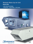
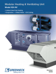
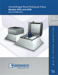
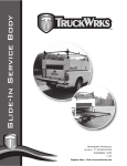
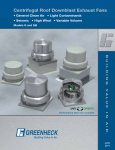
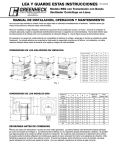
1
Centrifugal Exhaust Fans
Model USGF - Ultimate Steel Grease Fan
• Charbroilers, Solid Fuel Cooking, Oriental Cooking and High Wind Applications
February
2008
Ultimate Steel
Grease Exhaust Fan
Designed for severe grease applications...
When you choose a Greenheck USGF fan, you have selected a fan with the industry’s best performance and
durability for heavy grease applications (as stated in NFPA’s Chapter 11 restaurants and food service where
high amounts of grease and/or solid fuels are used). The USGF fan is specifically designed for severe grease
applications and to discharge air directly away from the mounting surface.
• Leakproof construction for the entire life of the fan utilizing a one-piece steel windband that is
continuously welded to the curb cap.
• Only spun steel fan in the industry.
• Performance up to 3.25 in. wg (810 Pa) and 6,800 cfm (11,550 m3/hr).
• Withstands the most severe cleaning conditions.
• Most advanced motor cooling of any grease fan. Capable of continuously handling 400° F airstream
temperatures.
• Performance as cataloged is assured. All fan sizes are tested in our AMCA Accredited Laboratory, and all
models are licensed to bear the AMCA Sound and Air performance seals.
• UL Listed for electrical and grease applications.
• Greenheck subjects these products to extensive life testing, assuring you that the fans will provide many
years of reliable performance.
• Only kitchen exhaust fan to meet Miami-Dade Test protocols for large Missile Impact Test.
Greenheck Fan Corporation certifies that the
Model USGF fan shown herein is licensed to bear
the AMCA Seal. The ratings shown are based on
tests and procedures performed in accordance
with AMCA Publication 211 and Publication 311
and comply with the requirements of the AMCA
Certified Ratings Program. The certified ratings
for Model USGF are shown on pages 10 to 18.
Model USGF is listed for
electrical (UL/cUL 705)
File no. E40001
Model USGF is listed for
grease removal (UL/cUL
762) File no. MH11745
Leading-Edge Technical Support
When you need extensive product and IOM (Installation
and Operating Manual) information, our products are
supported by the industry’s best product literature,
electronic media and computer aided selection
program (CAPS). You’ll also find this information on our
website at www.greenheck.com
You can always count on personal service and
expertise from our national and international
representative organization. To locate your nearest
Greenheck representative, call 715‑359‑6171 or visit our
website at www.greenheck.com
World-Class Manufacturing
Greenheck’s skilled production workers use cost-effective
machines and unique dies designed and built by our
own engineers to add innovative features and greater
strength to our centrifugal exhaust fans. Our advanced
manufacturing processes and quality control procedures
always ensure the highest product quality. And just to
be sure you get the peace-of-mind you expect when you
specify Greenheck, our assembly inspectors test run and
monitor every fan before it leaves the factory. Results
of these tests are kept in permanent records for future
reference.
Severe Weather
Applications
Forceful winds and wind-borne debris are the cause of most hurricane damage. Hurricane winds start
at 75 mph. At speeds of 140 mph wind can exert a 130 pound per square foot pressure or 900 pounds
of force on a fan and curb. Forceful winds are not the only problem; wind-borne debris can also cause
detrimental effects to objects and structures.
Miami-Dade County has the strictest test protocols in the country for wind-borne debris and wind
loading tests. Greenheck has gone one step further with the model USGF by third-party testing to the
Miami-Dade County Test Protocols.
These protocols were designed to protect against wind-born debris and severe wind loads.
• Structural Performance per Dade County Protocol TAS 202 (ASTM E-330).
• Large Missile Impact Testing per Dade County Protocol TAS 201.
Structural Performance Load: A static load that is 1.5 times the design load (195 pounds per square
foot pressure) is applied both positive and negative to simulate wind force loads in each direction.
Large Missile Impact Test: Is required when objects are located 30 feet or less from the ground. The
test unit is impacted three times with a piece of lumber (2 in. x 4 in. x 6 ft) weighing approximately nine
pounds and traveling at 34 mph. This simulates wind-borne debris striking the fan.
Miami-Dade County test protocols: Greenheck has gone the extra mile and worked with Miami-Dade
County to design a High Velocity Hurricane Zone standard for rooftop fans. The USGF has become the
first rooftop fan certified and approved by the Miami Dade Building Code Compliance office and Texas
Department of Insurance for use in hurricane zones. The certifications can be viewed on the Miami-Dade
County website under NOA #07-0503.06 or the Texas Department of Insurance Windstorm website.
When severe weather is a threat, don’t specify anything less than the Greenheck model USGF and the
SD curb.
Standard
Construction Features
1
2
3
4
5
6
7
8
9
Fan Shaft - Is 1-inch minimum in diameter and is
precisely sized, ground, and polished so the first
critical speed is at least 25% over the maximum
operating speed, which results in longer fan life.
Bearings - Lubricatable cast pillow block and are
air handling quality extended life L10 > 100,000
hours (L50 average life > 500,000 hours)
True Vibration Isolation - Lowers sound levels
and reduces vibration, which increases the fans
life since true vibration has no steel to steel
contact.
Clean Out Port - Allows the outside of the wheel
to be cleaned through a four-inch diameter
removable plug in the windband.
Non-Stick Coated Steel Wheel - Heavy
weight steel wheel with a dry lubricate
coating eliminates imbalance in heavy grease
applications. The steel wheel is a backwardinclined, non-overloading centrifugal type.
Drain Trough - All grease and water is collected
at one-point for easy disposal.
Curb Cap with Mounting Holes - Prepunched
mounting holes in the steel curb cap to ensure
correct attachment to the roof.
Hinged Curb Cap with Cables - Allows entire fan
to tilt away for access to wheel and ductwork
for inspection and cleaning. Shipped for field
assembly.
Leakproof Construction - One-piece fully welded
windband to curb cap. Assures no grease will
leak onto roof through the fan’s seams.
10 Drive Assembly - Dual belts, pulleys, and keys are
11
12
13
14
15
16
17
18
19
oversized 150% of driven horsepower. Machined
cast steel pulleys are adjustable for final system
balancing. Belts are static free and oil resistant.
Motor Cover - Is easily removed for access to the
steel motor compartment and drive assembly.
Powder Coated - Unit is constructed of a minimum
of 16 gauge galvaneal steel. Entire unit is powder
coated with a chemical resistant Permatector
finish.
Motor - Carefully matched to the fan load and is
mounted out of air stream.
Windband - Unique spun from galvaneal steel
achieves superior strength & consistent material
thickness.
Nema-3R Disconnect Switch Mounted & Wired Motor and switch are prewired to specified voltage.
Motor Cooling Tube - Maximum motor life is
achieved through positive motor cooling with fresh
outside air being continuously drawn through the
large breather tube directly over the motor.
Name Plate - Exact model and serial identification
on a permanent stamped aluminum plate.
Heat Baffle - Extends motor life by reducing the
amount of heat that penetrates through the bottom
of the motor support pan.
Lifting Lugs - Located under motor compartment
for ease of lifting unit during installation.
1
11
10
2
12
14
13
4
3
18
8
15
16
19
5
17
9
6
7
Options and Accessories
Self Draining Grease System:
Drain grease and rain water
back through the ductwork
into the specially designed
Greenheck hood. The hood
then channels grease and rain
water into the restaurant’s floor
grease trap.
Vented Curb Extension:
Mounts between roof
curb and roof mounted
fans to meet NFPA
requirements of 40 in.
minimum discharge
above the roof when
mounted on a minimum
8 in. high roof curb.
Coatings: Wide variety of coatings and colors are
available for decorative to acidic applications.
Severe Duty Curb: Model SD is specifically
designed for the optional hurricane use. It is
attached directly to the building structure with
extremely high structural design load requirements.
Maximum design load is 130 psf.
PERMATECTOR®
HI-PRO
POLYESTER
HI-PRO
POLYESTER
BAKED
ENAMEL
Permatector™ is our standard coating.
Typically used for applications that
require corrosion resistance in indoor
and outdoor environments.
Hi-Pro Polyester is resistant to salt
water, chemical fumes and moisture in
more corrosive atmospheres. Typically
used for applications that require
superior chemical resistance, excellent
abrasion and outdoor UV protection. This
coating exceeds protective qualities of
Air Dried Heresite and Air Dry Phenolic.
Baked Enamel Decorative Coatings
are heat cured enamels applied either
as wet paints or electrostatic powders.
Customers can choose from 16 standard
decorative colors or color match any
color.
Windband Extension: Tube that raises fans
discharge an additional 36 in. for special code
requirements.
Curb Seal: Rubber seal between fan and curb to
assure proper sealing when attached to a curb.
Roof Curbs: Wide variety of roof curbs are
available for mounting the fan to the roof, including:
vented, flanged, pitched.
Drain Connection:
Allows for single point
drainage of grease, water
or other residues.
Grease Trap: Aluminum
trap designed to collect
grease residue to avoid
drainage onto roof
surface.
Grease Trap with
Absorbent Material:
Same as above with an
absorbent material to
collect grease residue
and repel water for easy
periodic disposal.
Tie Down Points: Four
brackets located on the
windband for securing
the fan in heavy wind
applications.
Velocity Accelerator: Increases fan outlet/
discharge velocity. Up to 3,000 feet per minute.
Kitchen Ventilation
Solutions
Typical Installation - Commercial Kitchen (Grease)
The USGF is specifically designed for heavy restaurant grease
and food service applications. These fans are UL and cUL Listed
for grease removal and have been tested under high temperature
(400° F) and abnormal flare-up (600° F) conditions.
NEMA 3R
Disconnect
factory wired
from motor to
disconnect
through the
breather tube
(Optional)
Due to high temperatures and grease-laden airstreams in
commercial kitchen ventilation, system designers must be aware
of governing codes and guidelines. The National Fire Protection
Association (NFPA) is the primary source upon where many
codes for commercial kitchens ventilation are based. Selected
information from NFPA is shown below. Local code authorities
should be consulted before proceeding with any kitchen
ventilation project.
Mounting
Bolt Hole
Circle
Reco
Wall
Minimum 40"
Discharge
Height
Welded Duct
by others
min. of 18 in.
above roof
deck per
NFPA
Grease
Trap
Vented Curb
Extension
External Wiring
Liquid Tight
Flexible Conduit
by Others
8"min.
Roof Deck
Recommended
Roof Opening
Exhaust fans used in kitchen ventilation applications must have
external wiring. (Wiring must not be installed in airstream.)
Installation must include a means for inspecting, cleaning and servicing the exhaust fan.
(e.g. Hinged Curb Cap)
No dampers are to be installed in the system.
Our Hoods and Filters.
1
Greenheck’s
Performance
Enhancing Lip
(PEL) helps direct
air to the filter and
improves capture and
performance
2
Full length, fully welded
integral grease trough
3
An integral 3-inch
airspace that meets
NFPA 96 clearance
requirements against
limited combustibles
4
Constructed of 304 /
430 18 ga. stainless
steel.
5
Standing seam
construction for added
strength
6
Redesigned flat light
panels allows for lights
to be installed vertically
and simplified field
installation
7
Fully welded joints - no
caulk
6
5
4
3
7
2
Grease Grabber™
dual filtration system
works with the
Grease-X-Tractor™
filter to remove 80%
of the grease from
the kitchen exhaust.
Available in stainless
steel.
The Grease-XTractor™ high
efficiency filter has
twice the grease
extraction capability
of a baffle filter.
Available in aluminum
or stainless steel.
1
The high velocity
cartridge filters
offers dry cartridge
performance at
a lower cost.
Available in
aluminum or
stainless steel.
Baffle type filters
are the traditional
choice for
inexpensive grease
removal. Available
in aluminum,
stainless steel, or
non-stick coated.
Typical Installation and
Anchoring
Typical Mounting - Fan to Curb
Fastener 4 in. (102 mm)
from curb edge
H-GPF or SD curb
1/4 in. (6 mm) fastener minimum
5/16 in. (8 mm) recommended
See table for fastener quantities
USGF
Size
Fasteners
Per Side
Total
Fasteners
140 - 160
5
20
180 - 200
5
20
Fasteners on each side of the
fan are to be installed with one
fastener 4 in. (102 mm) from each
edge and one fastener centered.
The remaining fasteners are to be
equally spaced.
FAN TO CURB MOUNTING DETAIL
Concrete Deck Anchoring
Outside of Roof Curb
1 in. (25 mm) less than Fan Curb Cap
Corner Detail
H-GPF Curb Height
8 to 18 in. (203 to 457 mm)
(Optional 24 in. (610 mm) SD Curb)
11/4 in. (32 mm)
Use 3/8 in. (10 mm) expansion anchor
or equal into concrete.
Fasteners one on each corner as
detailed.
Each side at center of unit. Maximum
fastener spacing of 8 in. (203 mm),
add additional fasteners to satisfy.
1 in. (25 mm) Insulation
Roof Opening
2-1/2 in. (64 mm)
Embedment Recommended
minimum 1-5/8 in. (41 mm)
Minimum Concrete
Strength of 2000 PSI
11/4 in.
(32 mm)
Minimum 1-3/4 in. (44 mm)
edge distance
Center fasteners
on flange
5 in. (127 mm) Mounting Flange
Outside Flange
USGF
Size
Fan Curb Cap
Roof Opening
Fasteners Per Side
Outside Flange
141 - 161
22 x 22 (559 x 559)
181/2 x 181/2 (470 x 470)
5
31 x 31 (787 x 787)
180 - 200
30 x 30 (762 x 762)
201/2 x 201/2 (521 x 521)
7
39 x 39 (991 x 991)
All dimensions in inches (millimeters).
CONCRETE DECK ANCHORING DETAIL
Typical Anchoring
Metal Building/Steel Deck Anchoring
Outside of Roof Curb
1 in. (25 mm) less than
Fan Curb Cap
Use #12-14 self-drilling screws or equal.
Fasteners one on each corner as detailed.
Each side at center of unit. Maximum
fastener spacing of 8 in. (203 mm), add
additional fasteners to satisfy.
Corner Detail
1 in. (25 mm) Insulation
H-GPF Curb Height
8 to 18 in. (203 to 457 mm)
(Optional 24 in. (610 mm) SD Curb)
11/4 in. (32 mm)
Roof Opening
Corrugated Roof Deck
11/4 in.
(32 mm)
Minimum 12 ga Steel
Roof Truss
5 in. (127 mm) Mounting Flange
Center fasteners
on flange
Outside Flange
USGF
Size
Fan Curb Cap
Roof Opening
Fasteners Per Side
Outside Flange
141 - 161
22 x 22 (559 x 559)
181/2 x 181/2 (470 x 470)
5
31 x 31 (787 x 787)
180 - 200
30 x 30 (762 x 762)
201/2 x 201/2 (521 x 521)
7
39 x 39 (991 x 991)
All dimensions in inches (millimeters).
Wood Deck Anchoring
Outside of Roof Curb
1 in. (25 mm) less than
Fan Curb Cap
Corner Detail
Use #12 Wood Screws or equal into
minimum No. 1/No. 2 Southern Pine wood
support.
Fasteners one on each corner as detailed.
Each side at center of unit. Maximum
fastener spacing of 6 in. (152 mm), add
additional fasteners to satisfy.
1 in. (25 mm) Insulation
H-GPF Curb Height
8 to 18 in. (203 to 457 mm)
(Optional 24 in. (610 mm) SD Curb)
11/4 in. (32 mm)
Roof Opening
11/4 in.
(32 mm)
2 in. (51 mm) Minimum Embedment
Wood Decking
5 in. (127 mm) Mounting Flange
Center fasteners
on flange
Wood Support Member
Nominal 2 x 4, 6, 8
Outside Flange
USGF
Size
Fan Curb Cap
Roof Opening
Fasteners Per Side
Outside Flange
140 - 160
22 x 22 (559 x 559)
181/2 x 181/2 (470 x 470)
7
31 x 31 (787 x 787)
180 - 200
30 x 30 (762 x 762)
201/2 x 201/2 (521 x 521)
7
39 x 39 (991 x 991)
All dimensions in inches (millimeters).
Model Number Code
The Model number system is designed to completely identify the fan. The correct code letters must be
specified to designate the correct configuration. The remainder of the model number is determined by the
size and performance selected from the following pages.
USGF - 140 HP - 5
Configuration
Motor HP
Ultimate Steel Grease Fan
4 = 1⁄4 10 = 1
30 = 3
3 = 1⁄3 15 = 11⁄2
50 = 5
Fan Size
5 = 1⁄2 20 = 2
75 = 71⁄2
140 through 200
7 = 3⁄4
Pressure Level
HP - High Pressure Wheel
XP - Extended High Pressure Wheel
USGF-140 - Belt Drive
H-
ft o
f th
is s
yste
mc
urve
W.G.
287⁄8
(733)
293⁄4*
19 ⁄8 (756)
(492)
ele
ct
to
t
he
le
3
26
(660)
13⁄4
(44)
Do
no
ts
Roof Opening = 181/2 x 181/2 (470 x 470)
Windband Thickness = 0.051 (1.3)
Motor Cover Thickness = 0.040 (1.0)
Curb Cap Thickness = 0.064 (1.6)
^Approximate Unit Weight = 125 lb. (57 kg)
All dimensions in inches (millimeters).
*May be greater depending on motor.
^Weight shown is largest cataloged Open Drip Proof motor.
Model
Number
Motor
hp
USGF-140-4
1/4
Fan
rpm
590
715
840
965
1105
USGF-140-3
1/3
1210
USGF-140-5
1/2
1290
1390
USGF-140-7
3/4
1495
1595
USGF-140-10
1
1725
CFM
BHP
Sones
CFM
BHP
Sones
CFM
BHP
Sones
CFM
BHP
Sones
CFM
BHP
Sones
CFM
BHP
Sones
CFM
BHP
Sones
CFM
BHP
Sones
CFM
BHP
Sones
CFM
BHP
Sones
CFM
BHP
Sones
0
1069
0.04
5.0
1295
0.06
6.0
1521
0.10
7.1
1748
0.15
8.6
2001
0.23
10.9
2192
0.30
12.2
2337
0.36
13.2
2518
0.45
14.9
2708
0.56
17.2
2889
0.69
20
3125
0.87
26
0.125
851
0.04
4.5
1130
0.07
6.0
1387
0.11
7.3
1635
0.16
8.7
1906
0.24
10.8
2106
0.31
12.2
2258
0.38
13.3
2445
0.47
14.7
2640
0.58
16.5
2826
0.70
19.0
3066
0.88
23
0.25
885
0.07
5.1
1217
0.11
6.8
1499
0.17
8.5
1793
0.25
10.6
2006
0.32
11.7
2166
0.39
12.7
2362
0.48
14.2
2565
0.6
16.3
2757
0.72
18.5
3005
0.90
22
CFM / Static Pressure in inches wg
0.375
0.5
0.75
1
1.25
1.5
1.75
MAXIMUM BHP AT A GIVEN RPM = (RPM/1726)3
MAXIMUM RPM = 1725
TIP SPEED (ft/min.) = RPM x 3.829
MAXIMUM MOTOR FRAME SIZE = 145T
AVERAGE DISCHARGE VELOCITY (FPM) = CFM/1.72
969
0.11
6.2
1333
0.17
8.1
1667
0.26
10.3
1896
0.33
11.6
2065
0.40
12.6
2271
0.50
13.2
2483
0.61
15.6
2683
0.74
19.5
2936
0.92
24
1103
0.17
7.7
1515
0.26
10.0
1773
0.34
11.2
1957
0.41
12.3
2174
0.51
12.9
2396
0.62
13.9
2602
0.75
16.1
2865
0.94
24
998
0.23
9.6
1443
0.34
10.9
1691
0.42
12.0
1949
0.52
12.1
2202
0.64
12.5
2430
0.77
13.3
2711
0.97
15.1
1221
0.37
11.3
1643
0.51
11.0
1967
0.65
12.2
2225
0.79
12.3
2539
0.99
13.4
1617
0.61
10.8
1968
0.78
12.6
2339
1.00
14.3
1568
0.72
11.6
2085
0.98
13.8
1704
0.91
13.8
Performance certified is for installation type A: Free inlet, Free outlet. Power rating (BHP) does not include transmission losses. Performance ratings do not include the effects
of appurtenances (accessories). The sound ratings shown are loudness values in fan sones at 5 ft (1.5 m) in a hemispherical free field calculated per AMCA Standard 301.
Values shown are for installation type A: Free inlet hemispherical sone levels. The AMCA Certified Ratings Seal applies to sone ratings only.
10
USGF-140HP - Belt Drive
H-
W.G.
s sys
tem
curv
e
287⁄8
(733)
293⁄4*
19 ⁄8 (756)
(492)
26
(660)
no
ts
ele
ct
to
th
e le
ft o
f thi
3
13⁄4
(44)
Do
Roof Opening = 181/2 x 181/2 (470 x 470)
Windband Thickness = 0.051 (1.3)
Motor Cover Thickness = 0.040 (1.0)
Curb Cap Thickness = 0.064 (1.6)
^Approximate Unit Weight = 125 lb. (57 kg)
All dimensions in inches (millimeters).
*May be greater depending on motor.
^Weight shown is largest cataloged Open Drip Proof motor.
Model
Number
Motor
hp
USGF-140HP-4
1/4
Fan
rpm
895
1037
1179
1321
1465
USGF-140HP-3
1/3
1605
USGF-140HP-5
1/2
1725
1845
USGF-140HP-7
3/4
1960
2035
2110
CFM
BHP
Sones
CFM
BHP
Sones
CFM
BHP
Sones
CFM
BHP
Sones
CFM
BHP
Sones
CFM
BHP
Sones
CFM
BHP
Sones
CFM
BHP
Sones
CFM
BHP
Sones
CFM
BHP
Sones
CFM
BHP
Sones
0.5
331
0.06
6.1
566
0.10
6.7
733
0.13
8.9
878
0.18
12.1
1016
0.24
14.2
1146
0.31
15.2
1256
0.38
16.1
1363
0.46
17.0
1463
0.54
18.1
1528
0.60
18.9
1592
0.67
19.8
0.75
1
CFM / Static Pressure in inches wg
1.25
1.5
1.75
2
2.25
2.5
2.75
MAXIMUM BHP AT A GIVEN RPM = (RPM/2285)3
MAXIMUM RPM = 2110
TIP SPEED (ft/min.) = RPM x 3.829
MAXIMUM MOTOR FRAME SIZE = 145T
AVERAGE DISCHARGE VELOCITY (FPM) = CFM/1.72
563
0.14
9.2
756
0.19
11.6
920
0.26
13.5
1063
0.33
14.4
1178
0.40
15.4
1292
0.48
16.6
1399
0.57
17.7
1468
0.63
18.5
1536
0.70
19.3
591
0.19
13.6
798
0.26
13.2
965
0.34
14.2
1098
0.42
15.0
1219
0.50
16.2
1330
0.59
17.4
1402
0.66
18.2
1473
0.72
19.1
642
0.26
15.5
846
0.34
14.0
999
0.43
14.9
1137
0.52
16.0
1260
0.61
17.2
1335
0.68
18.0
1409
0.75
19.0
704
0.34
15.2
879
0.43
14.7
1042
0.52
15.9
1176
0.62
17.1
1261
0.69
18.0
1341
0.77
18.9
747
0.42
15.7
924
0.52
15.6
1086
0.63
17.0
1175
0.70
17.8
1262
0.78
18.8
800
0.51
16.1
970
0.62
16.8
1077
0.70
17.7
1178
0.78
18.6
854
0.62
16.9
965
0.69
17.5
1073
0.78
18.5
826
0.67
17.8
965
0.77
18.3
804
0.73
20
Performance certified is for installation type A: Free inlet, Free outlet. Power rating (BHP) does not include transmission losses. Performance ratings do not include the effects
of appurtenances (accessories). The sound ratings shown are loudness values in fan sones at 5 ft (1.5 m) in a hemispherical free field calculated per AMCA Standard 301.
Values shown are for installation type A: Free inlet hemispherical sone levels. The AMCA Certified Ratings Seal applies to sone ratings only.
11
USGF-160 - Belt Drive
H-
mc
urv
e
W.G.
287⁄8
(733)
th i
s sy
ste
293⁄4*
19 ⁄8 (756)
(492)
le
ct
to
th
el
ef t
of
3
26
(660)
13⁄4
(44)
Do
t
no
se
Roof Opening = 181/2 x 181/2 (470 x 470)
Windband Thickness = 0.051 (1.3)
Motor Cover Thickness = 0.040 (1.0)
Curb Cap Thickness = 0.064 (1.6)
^Approximate Unit Weight = 131 lb. (59 kg)
All dimensions in inches (millimeters).
*May be greater depending on motor.
^Weight shown is largest cataloged Open Drip Proof motor.
Model
Number
Motor
hp
USGF-160-4
1/4
Fan
rpm
730
778
826
875
USGF-160-3
1/3
965
USGF-160-5
1/2
1038
1110
USGF-160-7
3/4
1188
1265
USGF-160-10
1
1328
1390
CFM
BHP
Sones
CFM
BHP
Sones
CFM
BHP
Sones
CFM
BHP
Sones
CFM
BHP
Sones
CFM
BHP
Sones
CFM
BHP
Sones
CFM
BHP
Sones
CFM
BHP
Sones
CFM
BHP
Sones
CFM
BHP
Sones
0
2098
0.13
8.1
2236
0.16
8.9
2374
0.20
9.9
2515
0.23
11.0
2774
0.31
12.4
2984
0.39
13.7
3191
0.47
15.0
3415
0.58
16.7
3636
0.70
18.5
3817
0.81
20
3996
0.93
22
0.125
1905
0.15
8.0
2058
0.18
8.7
2209
0.22
9.6
2362
0.26
10.6
2637
0.34
12.0
2857
0.42
13.3
3072
0.51
14.6
3304
0.62
16.3
3532
0.74
18.1
3718
0.85
19.6
3901
0.97
21
0.25
1669
0.15
7.8
1843
0.19
8.5
2010
0.22
9.3
2177
0.26
10.1
2477
0.35
11.5
2712
0.43
12.8
2941
0.53
14.2
3186
0.64
15.8
3426
0.77
17.7
3619
0.89
19.2
3806
1.01
21
CFM / Static Pressure in inches wg
0.375
0.5
0.625
0.75
1
1.25
1.5
1389
MAXIMUM BHP AT A GIVEN RPM = (RPM/1365)3
0.15
MAXIMUM RPM = 1390
7.8
TIP SPEED (ft/min.) = RPM x 4.352
1596
MAXIMUM MOTOR FRAME SIZE = 145T
0.18
AVERAGE DISCHARGE VELOCITY (FPM) = CFM/1.72
8.4
1790
1512
0.22
0.21
9.1
9.0
1974
1744
1365
0.26
0.26
0.24
9.9
9.7
9.7
2300
2109
1893
1584
0.35
0.35
0.34
0.33
11.2
10.8
10.6
10.5
2552
2382
2199
1992
0.44
0.44
0.43
0.43
12.4
12.1
11.8
11.6
2796
2641
2475
2297
1770
0.53
0.54
0.53
0.52
0.49
13.8
13.5
13.1
12.9
12.2
3053
2911
2764
2606
2246
0.65
0.65
0.66
0.65
0.64
15.4
15.0
14.7
14.5
14.0
3301
3172
3036
2894
2583
2163
0.78
0.79
0.79
0.79
0.78
0.75
17.2
16.8
16.5
16.3
15.8
15.2
3502
3383
3253
3124
2843
2510
0.90
0.91
0.91
0.92
0.90
0.89
18.7
18.3
18.0
17.8
17.4
16.9
3698
3584
3464
3340
3078
2785
2394
1.03
1.04
1.04
1.05
1.04
1.03
1.00
20
19.9
19.6
19.4
19.0
18.6
18.0
Performance certified is for installation type A: Free inlet, Free outlet. Power rating (BHP) does not include transmission losses. Performance ratings do not include the effects
of appurtenances (accessories). The sound ratings shown are loudness values in fan sones at 5 ft (1.5 m) in a hemispherical free field calculated per AMCA Standard 301.
Values shown are for installation type A: Free inlet hemispherical sone levels. The AMCA Certified Ratings Seal applies to sone ratings only.
12
USGF-160HP - Belt Drive
H-
of
thi
s sy
ste
mc
ur v
e
W.G.
287⁄8
(733)
293⁄4*
19 ⁄8 (756)
(492)
le
ct
to
t
he
lef
t
3
26
(660)
t
no
Do
13⁄4
(44)
se
Roof Opening = 181/2 x 181/2 (470 x 470)
Windband Thickness = 0.051 (1.3)
Motor Cover Thickness = 0.040 (1.0)
Curb Cap Thickness = 0.064 (1.6)
^Approximate Unit Weight = 131 lb. (59 kg)
All dimensions in inches (millimeters).
*May be greater depending on motor.
^Weight shown is largest cataloged Open Drip Proof motor.
Model
Number
Motor
hp
USGF-160HP-4
1/4
Fan
rpm
825
910
995
1065
USGF-160HP-3
1/3
1165
USGF-160HP-5
1/2
1255
1340
USGF-160HP-7
3/4
1441
1535
USGF-160HP-10
1
1610
1690
CFM
BHP
Sones
CFM
BHP
Sones
CFM
BHP
Sones
CFM
BHP
Sones
CFM
BHP
Sones
CFM
BHP
Sones
CFM
BHP
Sones
CFM
BHP
Sones
CFM
BHP
Sones
CFM
BHP
Sones
CFM
BHP
Sones
0.5
889
0.12
7.0
1129
0.16
8.3
1331
0.21
9.6
1487
0.25
11.0
1697
0.32
12.8
1882
0.40
13.1
2053
0.48
14.4
2253
0.59
16.3
2433
0.70
18.1
2573
0.80
19.6
2722
0.92
21
0.625
956
0.16
7.8
1208
0.21
9.3
1377
0.26
10.6
1608
0.33
12.7
1799
0.41
12.8
1975
0.49
13.8
2180
0.60
15.8
2368
0.72
17.7
2516
0.82
19.2
2671
0.94
21
0.75
CFM / Static Pressure in inches wg
0.875
1
1.25
1.5
1.75
2
2.25
MAXIMUM BHP AT A GIVEN RPM = (RPM/1660)3
MAXIMUM RPM = 1690
TIP SPEED (ft/min.) = RPM x 4.352
MAXIMUM MOTOR FRAME SIZE = 145T
AVERAGE DISCHARGE VELOCITY (FPM) = CFM/1.72
1042
0.21
8.8
1252
0.26
10.2
1504
0.34
12.2
1715
0.42
12.5
1897
0.50
13.3
2108
0.61
15.2
2301
0.73
17.2
2452
0.83
18.8
2611
0.95
21
1093
0.26
9.8
1395
0.34
11.7
1617
0.43
12.0
1816
0.51
12.8
2036
0.63
14.7
2233
0.74
16.8
2387
0.85
18.4
2550
0.97
20
1252
0.34
11.3
1519
0.43
11.5
1724
0.52
12.3
1961
0.64
14.3
2165
0.76
16.4
2322
0.86
18.1
2488
0.98
20
1218
0.42
10.6
1513
0.52
11.3
1790
0.65
13.5
2015
0.78
15.7
2190
0.89
17.5
2365
1.01
19.5
1577
0.65
12.3
1855
0.79
14.9
2037
0.90
16.9
2228
1.03
19.1
1638
0.78
13.5
1863
0.91
15.8
2082
1.05
18.6
1651
0.90
14.3
1899
1.05
16.9
1664
1.03
15.0
Performance certified is for installation type A: Free inlet, Free outlet. Power rating (BHP) does not include transmission losses. Performance ratings do not include the effects
of appurtenances (accessories). The sound ratings shown are loudness values in fan sones at 5 ft (1.5 m) in a hemispherical free field calculated per AMCA Standard 301.
Values shown are for installation type A: Free inlet hemispherical sone levels. The AMCA Certified Ratings Seal applies to sone ratings only.
13
USGF-160XP - Belt Drive
H-
W.G.
this sy
stem cu
r
ve
287⁄8
(733)
left of
293⁄4*
19 ⁄8 (756)
(492)
26
(660)
Do
n ot
sele
ct to
the
3
13⁄4
(44)
Roof Opening = 181/2 x 181/2 (470 x 470)
Windband Thickness = 0.051 (1.3)
Motor Cover Thickness = 0.040 (1.0)
Curb Cap Thickness = 0.064 (1.6)
^Approximate Unit Weight = 131 lb. (59 kg)
All dimensions in inches (millimeters).
*May be greater depending on motor.
^Weight shown is largest cataloged Open Drip Proof motor.
Model
Number
Motor
hp
USGF-160XP-5
1/2
Fan
rpm
1550
1648
1750
USGF-160XP-7
3/4
1880
1942
2005
USGF-160XP-10
1
2138
2205
USGF-160XP-15
11/2
2310
2432
2525
CFM
BHP
Sones
CFM
BHP
Sones
CFM
BHP
Sones
CFM
BHP
Sones
CFM
BHP
Sones
CFM
BHP
Sones
CFM
BHP
Sones
CFM
BHP
Sones
CFM
BHP
Sones
CFM
BHP
Sones
CFM
BHP
Sones
1
968
0.34
10.0
1157
0.42
11.1
1322
0.52
12.1
1515
0.65
13.7
1599
0.71
14.3
1684
0.77
15.0
1861
0.93
16.6
1946
1.01
17.5
2076
1.17
19.0
2226
1.36
21
2339
1.52
22
1.25
854
0.39
10.2
1116
0.49
11.4
1359
0.63
13.1
1456
0.70
13.9
1552
0.78
14.7
1743
0.95
16.4
1834
1.03
17.3
1974
1.18
18.7
2134
1.36
20
2250
1.52
22
1.5
CFM / Static Pressure in nches wg
1.75
2
2.25
2.5
2.75
3
3.25
MAXIMUM BHP AT A GIVEN RPM = (RPM/2170)3
MAXIMUM RPM = 2525
TIP SPEED (ft/min.) = RPM x 3.534
MAXIMUM MOTOR FRAME SIZE = 145T
AVERAGE DISCHARGE VELOCITY (FPM) = CFM/1.72
726
0.43
10.9
1139
0.60
12.3
1271
0.68
13.2
1392
0.76
14.1
1611
0.94
15.9
1713
1.04
17.0
1865
1.2
18.5
2031
1.38
20
2155
1.54
22
744
0.52
12.2
984
0.63
12.6
1161
0.72
13.4
1451
0.91
15.4
1578
1.01
16.4
1741
1.18
18.1
1926
1.40
20
2056
1.56
22
777
0.63
13.6
1226
0.87
14.8
1395
0.99
15.9
1597
1.16
17.5
1804
1.38
19.6
1946
1.56
21
869
0.78
15.1
1127
0.92
15.5
1415
1.12
17.1
1660
1.35
19.1
1828
1.53
21
634
0.73
16.7
1134
1.04
16.8
1483
1.31
18.7
1676
1.50
20
644
0.83
18.4
1225
1.23
18.7
1487
1.45
20
826
1.07
19.9
1221
1.35
20
810
1.16
22
Performance certified is for installation type A: Free inlet, Free outlet. Power rating (BHP) does not include transmission losses. Performance ratings do not include the effects
of appurtenances (accessories). The sound ratings shown are loudness values in fan sones at 5 ft (1.5 m) in a hemispherical free field calculated per AMCA Standard 301.
Values shown are for installation type A: Free inlet hemispherical sone levels. The AMCA Certified Ratings Seal applies to sone ratings only.
14
USGF-180 - Belt Drive
H-
to
f th
is s
yst
em
cur
ve
W.G.
353⁄8
(899)
lec
t
to
the
lef
285⁄8*
21 (727)
(533)
30
(762)
13⁄4
(44)
D
s
ot
on
e
Roof Opening = 201/2 x 201/2 (521 x 521)
Windband Thickness = 0.051 (1.3)
Motor Cover Thickness = 0.040 (1.0)
Curb Cap Thickness = 0.064 (1.6)
^Approximate Unit Weight = 190 lb. (86 kg)
All dimensions in inches (millimeters).
*May be greater depending on motor.
^Weight shown is largest cataloged Open Drip Proof motor.
Model
Number
Motor
hp
USGF-180-4
1/4
Fan
rpm
630
745
USGF-180-3
1/3
820
USGF-180-5
1/2
940
USGF-180-7
3/4
1010
1075
USGF-180-10
1
1185
USGF-180-15
11/2
1275
1360
USGF-180-20
2
1430
1495
CFM
BHP
Sones
CFM
BHP
Sones
CFM
BHP
Sones
CFM
BHP
Sones
CFM
BHP
Sones
CFM
BHP
Sones
CFM
BHP
Sones
CFM
BHP
Sones
CFM
BHP
Sones
CFM
BHP
Sones
CFM
BHP
Sones
0
2380
0.13
7.1
2815
0.22
9.2
3098
0.30
11.2
3551
0.45
13.8
3816
0.56
15.4
4061
0.67
16.5
4477
0.90
18.5
4817
1.12
21
5138
1.36
23
5402
1.58
25
5648
1.80
28
0.125
2154
0.15
6.4
2617
0.24
8.6
2916
0.32
10.4
3389
0.47
13.5
3664
0.58
15.2
3919
0.70
16.2
4348
0.93
17.9
4697
1.15
20
5026
1.39
23
5296
1.62
25
5546
1.84
27
0.25
1861
0.16
5.5
2448
0.26
8.1
2759
0.34
10.0
3243
0.49
13.1
3526
0.61
14.9
3786
0.73
15.8
4224
0.96
17.1
4578
1.19
19.5
4913
1.43
22
5189
1.66
25
5443
1.89
27
CFM / Static Pressure in inches wg
0.5
0.75
1
1.25
1763
0.25
7.1
2257
0.34
9.0
2879
0.52
12.4
3242
0.65
14.7
3554
0.78
151.5
4005
1.01
16.5
4369
1.24
18.7
4710
1.49
21
4993
1.72
24
5254
1.96
26
1.5
1.75
2
MAXIMUM BHP AT A GIVEN RPM = (RPM/1167)3
MAXIMUM RPM = 1495
TIP SPEED (ft/min.) = RPM x 4.843
MAXIMUM MOTOR FRAME SIZE = 184T
AVERAGE DISCHARGE VELOCITY (FPM) = CFM/2.92
2363
0.50
11.2
2799
0.64
13.7
3141
0.78
14.7
3703
1.04
16.0
4163
1.30
18.2
4532
1.56
21
4819
1.79
23
5082
2.02
25
2105
0.58
11.8
2652
0.75
13.3
3336
1.04
15.2
3799
1.30
17.5
4232
1.58
20
4593
1.83
22
4921
2.10
25
2841
0.99
14.4
3437
1.28
16.7
3912
1.58
19.2
4270
1.83
22
4598
2.10
24
2930
1.22
15.9
3537
1.54
18.3
3968
1.83
21
4313
2.10
23
3023
1.46
17.3
3567
1.76
19.5
3983
2.06
22
3001
1.66
18.2
3564
1.99
21
Performance certified is for installation type A: Free inlet, Free outlet. Power rating (BHP) does not include transmission losses. Performance ratings do not include the effects
of appurtenances (accessories). The sound ratings shown are loudness values in fan sones at 5 ft (1.5 m) in a hemispherical free field calculated per AMCA Standard 301.
Values shown are for installation type A: Free inlet hemispherical sone levels. The AMCA Certified Ratings Seal applies to sone ratings only.
15
USGF-180HP - Belt Drive
H-
f th
is s
yst
em
cur
ve
W.G.
353⁄8
(899)
le c
tt
ot
he
lef
to
285⁄8*
21 (727)
(533)
30
(762)
e
ts
no
o
D
1 ⁄4
(44)
3
Roof Opening = 201/2 x 201/2 (521 x 521)
Windband Thickness = 0.051 (1.3)
Motor Cover Thickness = 0.040 (1.0)
Curb Cap Thickness = 0.064 (1.6)
^Approximate Unit Weight = 190 lb. (86 kg)
All dimensions in inches (millimeters).
*May be greater depending on motor.
^Weight shown is largest cataloged Open Drip Proof motor.
Model
Number
Motor
hp
USGF-180HP-4
1/4
Fan
rpm
795
845
USGF-180HP-3
1/3
925
USGF-180HP-5
1/2
1065
USGF-180HP-7
3/4
1215
USGF-180HP-10
1
1275
1335
USGF-180HP-15
11/2
1430
1530
USGF-180HP-20
2
1610
1685
CFM
BHP
Sones
CFM
BHP
Sones
CFM
BHP
Sones
CFM
BHP
Sones
CFM
BHP
Sones
CFM
BHP
Sones
CFM
BHP
Sones
CFM
BHP
Sones
CFM
BHP
Sones
CFM
BHP
Sones
CFM
BHP
Sones
0.5
1570
0.22
8.3
1799
0.26
9.5
2104
0.34
10.8
2581
0.50
13.8
3063
0.72
15.0
3253
0.82
16.7
3441
0.93
18.7
3735
1.13
22
4035
1.36
24
4273
1.58
25
4495
1.79
27
0.75
1
CFM / Static Pressure in inches wg
1.25
1.5
1.75
2
2.25
2.5
2.75
MAXIMUM BHP AT A GIVEN RPM = (RPM/1315)3
MAXIMUM RPM = 1685
TIP SPEED (ft/min.) = RPM x 4.843
MAXIMUM MOTOR FRAME SIZE = 184T
AVERAGE DISCHARGE VELOCITY (FPM) = CFM/2.92
1688
0.35
9.8
2323
0.52
12.5
2868
0.76
14.5
3066
0.87
15.8
3261
0.98
17.4
3566
1.19
21
3884
1.43
23
4136
1.64
24
4369
1.86
26
1933
0.53
12.4
2626
0.78
14.0
2853
0.89
15.4
3075
1.02
17.0
3401
1.23
19.7
3728
1.48
22
3986
1.70
23
4226
1.93
25
2286
0.79
13.4
2566
0.91
14.9
2839
1.04
16.6
3206
1.26
19.3
3574
1.53
21
3840
1.76
23
4085
1.99
26
1854
0.75
12.9
2209
0.89
14.3
2523
1.04
16.1
2964
1.27
18.9
3376
1.55
20
3674
1.79
22
3945
2.04
24
2156
1.01
15.6
2669
1.28
18.4
3135
1.56
19.8
3485
1.81
21
3768
2.07
23
2320
1.24
17.9
2859
1.57
19.3
3233
1.82
21
3575
2.08
22
2534
1.53
18.6
2965
1.82
20
3325
2.09
21
2656
1.78
19.2
3061
2.08
21
2766
2.04
20
Performance certified is for installation type A: Free inlet, Free outlet. Power rating (BHP) does not include transmission losses. Performance ratings do not include the effects
of appurtenances (accessories). The sound ratings shown are loudness values in fan sones at 5 ft (1.5 m) in a hemispherical free field calculated per AMCA Standard 301.
Values shown are for installation type A: Free inlet hemispherical sone levels. The AMCA Certified Ratings Seal applies to sone ratings only.
16
USGF-200 - Belt Drive
H-
is sy
stem
curv
e
W.G.
353⁄8
(899)
ot
se
lec
t
to
the
left
of t
h
285⁄8*
21 (727)
(533)
30
(762)
n
Do
13⁄4
(44)
Roof Opening = 201/2 x 201/2 (521 x 521)
Windband Thickness = 0.051 (1.3)
Motor Cover Thickness = 0.040 (1.0)
Curb Cap Thickness = 0.064 (1.6)
^Approximate Unit Weight = 213 lb. (97 kg)
All dimensions in inches (millimeters).
*May be greater depending on motor.
^Weight shown is largest cataloged Open Drip Proof motor.
Model
Number
Motor
hp
USGF-200-4
1/4
Fan
rpm
500
605
USGF-200-3
1/3
665
USGF-200-5
1/2
760
USGF-200-7
3/4
820
875
USGF-200-10
1
960
USGF-200-15
11/2
1030
1100
USGF-200-20
2
1155
1210
CFM
BHP
Sones
CFM
BHP
Sones
CFM
BHP
Sones
CFM
BHP
Sones
CFM
BHP
Sones
CFM
BHP
Sones
CFM
BHP
Sones
CFM
BHP
Sones
CFM
BHP
Sones
CFM
BHP
Sones
CFM
BHP
Sones
0
2812
0.14
6.2
3403
0.25
8.1
3740
0.33
9.4
4275
0.49
12.1
4612
0.61
14.1
4922
0.75
16.3
5400
0.98
18.7
5793
1.22
21
6187
1.48
23
6496
1.72
24
6806
1.97
25
0.125
2386
0.15
5.4
3054
0.26
7.4
3422
0.34
8.8
3994
0.51
11.7
4350
0.63
14.1
4676
0.77
16.3
5176
1.01
18.4
5585
1.24
21
5992
1.51
23
6311
1.74
24
6628
2.00
24
0.25
1822
0.15
4.6
2675
0.26
6.7
3096
0.35
8.1
3718
0.52
10.9
4098
0.65
13.0
4439
0.78
15.2
4958
1.03
17.7
5380
1.26
20
5798
1.53
23
6125
1.77
23
6451
2.03
23
CFM / Static Pressure in inches wg
0.375
0.5
0.75
1
2144
0.25
6.1
2699
0.35
7.5
3413
0.52
10.1
3828
0.65
12.2
4192
0.79
14.7
4742
1.04
17.0
5179
1.28
19.2
5610
1.55
22
5946
1.79
23
6279
2.05
23
1.25
1.5
1.75
MAXIMUM BHP AT A GIVEN RPM = (RPM/946)3
MAXIMUM RPM = 1210
TIP SPEED (ft/min.) = RPM x 5.595
MAXIMUM MOTOR FRAME SIZE = 184T
AVERAGE DISCHARGE VELOCITY (FPM) = CFM/2.92
2073
0.33
7.0
3048
0.51
9.4
3523
0.65
11.4
3922
0.79
13.5
4508
1.04
16.4
4968
1.29
18.7
5421
1.57
21
5767
1.81
22
6108
2.07
22
2606
0.61
10.7
3240
0.78
12.4
3985
1.04
15.0
4503
1.29
17.5
5006
1.57
20
5383
1.81
21
5748
2.09
21
3169
1.00
14.4
3917
1.27
16.4
4529
1.57
19.3
4948
1.81
20
5350
2.09
21
2972
1.18
16.8
3861
1.53
18.6
4410
1.80
19.2
4892
2.08
19.8
3629
1.71
19.9
4289
2.04
19.7
3365
1.88
21
Performance certified is for installation type A: Free inlet, Free outlet. Power rating (BHP) does not include transmission losses. Performance ratings do not include the effects
of appurtenances (accessories). The sound ratings shown are loudness values in fan sones at 5 ft (1.5 m) in a hemispherical free field calculated per AMCA Standard 301.
Values shown are for installation type A: Free inlet hemispherical sone levels. The AMCA Certified Ratings Seal applies to sone ratings only.
17
USGF-200HP - Belt Drive
H-
30
(762)
tt
ot
he
lef
t
of
th
is s
yst
em
c
285⁄8*
21 (727)
(533)
urv
e
W.G.
353⁄8
(899)
ec
13⁄4
(44)
t
no
Do
Roof Opening = 201/2 x 201/2 (521 x 521)
Windband Thickness = 0.051 (1.3)
Motor Cover Thickness = 0.040 (1.0)
Curb Cap Thickness = 0.064 (1.6)
^Approximate Unit Weight = 213 lb. (97 kg)
l
se
All dimensions in inches (millimeters).
*May be greater depending on motor.
^Weight shown is largest cataloged Open Drip Proof motor.
Model
Number
Motor
hp
USGF-200HP-5
1/2
Fan
rpm
740
880
USGF-200HP-7
3/4
945
1010
USGF-200HP-10
1
1110
USGF-200HP-15
11/2
1190
1270
USGF-200HP-20
2
1335
1400
USGF-200HP-30
3
1465
1600
CFM
BHP
Sones
CFM
BHP
Sones
CFM
BHP
Sones
CFM
BHP
Sones
CFM
BHP
Sones
CFM
BHP
Sones
CFM
BHP
Sones
CFM
BHP
Sones
CFM
BHP
Sones
CFM
BHP
Sones
CFM
BHP
Sones
0.5
2024
0.31
8.1
2779
0.51
10.5
3094
0.62
12.2
3397
0.75
14.5
3851
0.98
16.9
4207
1.20
19.0
4558
1.44
22
4837
1.67
23
5110
1.91
24
5382
2.18
26
5943
2.81
29
0.75
2317
0.52
9.5
2711
0.64
11.5
3067
0.78
13.7
3561
1.02
16.2
3944
1.24
18.1
4312
1.49
21
4606
1.71
23
4898
1.96
24
5186
2.23
25
5775
2.88
28
1
CFM / Static Pressure in inches wg
1.25
1.5
1.75
2
2.25
2.5
2.75
MAXIMUM BHP AT A GIVEN RPM = (RPM/1093)3
MAXIMUM RPM = 1600
TIP SPEED (ft/min.) = RPM x 5.595
MAXIMUM MOTOR FRAME SIZE = 184T
AVERAGE DISCHARGE VELOCITY (FPM) = CFM/2.92
2092
0.62
10.6
2637
0.79
13.2
3242
1.04
15.7
3661
1.27
17.5
4055
1.53
20
4369
1.76
22
4674
2.01
24
4972
2.28
25
5581
2.93
29
2806
1.04
15.5
3321
1.29
17.3
3789
1.56
19.7
4116
1.79
21
4436
2.05
23
4752
2.33
25
5385
2.99
30
2850
1.26
17.5
3433
1.56
19.3
3826
1.82
21
4195
2.09
21
4521
2.37
23
5182
3.03
29
2944
1.53
19.8
3482
1.82
21
3880
2.09
22
4269
2.40
23
4971
3.08
26
2946
1.75
22
3515
2.08
23
3956
2.40
24
4760
3.13
24
3556
2.37
25
4476
3.13
26
4189
3.13
28
3760
3.06
31
Performance certified is for installation type A: Free inlet, Free outlet. Power rating (BHP) does not include transmission losses. Performance ratings do not include the effects
of appurtenances (accessories). The sound ratings shown are loudness values in fan sones at 5 ft (1.5 m) in a hemispherical free field calculated per AMCA Standard 301.
Values shown are for installation type A: Free inlet hemispherical sone levels. The AMCA Certified Ratings Seal applies to sone ratings only.
18
Specifications
Spun steel exhaust fans shall be centrifugal belt driven type. Fan wheel shall be centrifugal backward
inclined type. The wheel shall be constructed of steel and coated with a non-stick coating similar to Teflon®
as manufactured by Du Pont®. Wheel shall include a wheel cone carefully matched to the inlet cone for
precise running tolerances. Wheels shall be statically and dynamically balanced.
The fan housing shall be constructed of 16 gauge galvaneal steel with a rigid internal support structure and
shall be leakproof. The fan housing shall be constructed with a one piece windband with an integral rolled
bead for added strength and shall be joined to the curb cap with a continuously welded seam.
Fan’s windband shall have a clean out port, a 4-inch diameter hole on the outside of the fan’s windband
with a grease repellent compression rubber fit, allowing access to entire wheel for cleaning.
Motors shall be heavy duty ball bearing type, carefully matched to the fan load, and furnished at the
specified voltage, phase and enclosure. Drive frame assembly shall be constructed of heavy gauge
galvanized steel. Motors and drives shall be mounted on heavy duty true vibration isolators, out of the
airstream. Fresh air for motor cooling shall be drawn into the motor compartment through a ten square inch
tube free of discharge contaminants. Motors and drives shall be readily accessible for maintenance.
Precision ground and polished 1-inch minimum diameter fan shafts shall be mounted in cast pillow block
lubricatable ball bearings. Bearings shall be selected for a minimum L10 life in excess of 100,000 hours
(L50 average life of 500,000 hours) at maximum cataloged operating speed. Dual drives shall be sized for a
minimum of 150% of driven horsepower. Pulleys shall be of the cast type, keyed and securely attached to
the wheel and motor shafts.
Motor pulleys shall be adjustable for final system balancing. All fans shall have a dual belt and pulley
system. A NEMA‑3R disconnect switch shall be factory installed and wired from the fan motor to a junction
box installed outside the motor compartment.
All fans shall bear the AMCA Certified Ratings Seal
for sound and air performance.
Each fan shall bear a permanently affixed
manufacturer’s engraved metal nameplate containing
the model number and individual serial number for
future identification.
Fans shall be Listed by Underwriters Laboratory for
UL/cUL 762 Listed for all electrical components and
grease removal.
Hinge kit shall be constructed of heavy gauge
hinges and shall include hold open cables for field
installation.
Grease trap shall include the drain connection. The
unit shall collect grease and water from the fan and
extract the grease from the water for ease of grease
disposal.
Fans shall be model USGF as manufactured by
Greenheck Fan Corporation in Schofield, Wisconsin.
19
19
Additional Grease
Exhaust Solutions
Series C models CUE, CUBE, CW and CWB are commonly used for
general clean air, mild grease and fume hood exhaust applications.
Both Roof Upblast and Sidewall configurations are specifically
designed to discharge air directly away from the mounting surface.
These models are constructed of aluminum and use an aluminum
backward inclined wheel. They are UL Listed for electrical or grease.
Performance capacities ranges up to 5 in. wg (1250 Pa) and up to
30,000 cfm (51,000 m3/hr).
Model SWB centrifugal backward inclined belt driven utility fans are
designed for supply, exhaust and return air applications requiring higher
discharge velocities and high static pressures. The SWB Series 100 is for
general clean air applicators. The SWB Series 200 fans are constructed
with heavy gauge steel. Designed for light industrial duty and grease
applications with capacities ranges up to 2,7000 cfm (45,900 m3/hr) and up
to 5 in. wg (1250 Pa) of static pressure. SWB fans can be mounted indoors
or outdoors.
Model TCB inline belt driven fans are the ideal choice for installations
with straight-through air flow in ducted systems. The wheels used are
designed to provide higher efficiencies and lower sound levels. The fan
itself can be mounted horizontally or vertically. Performance capacities
ranges up to 24,000 cfm (40,800 m3/hr) and up to 4 in. wg (1,000 Pa) of
static pressure.
Building Value in Air
Greenheck delivers value
top quality, innovative air-
And building owners and
to mechanical engineers by
related equipment. We offer
occupants value the energy
helping them solve virtually
extra value to contractors
efficiency, low maintenance
any air quality challenges
by providing easy-to-install,
and quiet dependable operation
their clients face with a
competitively priced, reliable
they experience long after the
comprehensive selection of
products that arrive on time.
construction project ends.
Our Warranty
Greenheck warrants this equipment to be free from defects in material and workmanship for a period
of one year from the purchase date. Any units or parts which prove defective during the warranty
period will be replaced at our option when returned to our factory, transportation prepaid. Motors are
warranted by the motor manufacturer for a period of one year. Should motors furnished by Greenheck
prove defective during this period, they should be returned to the nearest authorized motor service
station. Greenheck will not be responsible for any removal or installation costs.
As a result of our commitment to continuous improvement, Greenheck reserves the right to change
specifications without notice.
Prepared to Support
Green Building Efforts
P.O. Box 410 • Schofield, WI 54476-0410 • Phone (715) 359-6171 • greenheck.com
Catalog USGF Rev. 5 February 2008
Copyright © 2008 Greenheck Fan Corp.