1
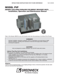
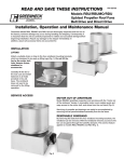
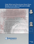
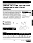
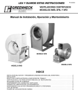
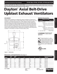
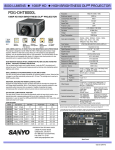
READ AND SAVE THESE INSTRUCTIONS
Part # 453905
TUBE AXIAL UPBLAST FANS
Model TAUD (Direct Drive, Aluminum Propeller)
Model TAUB-CA (Belt Drive, Aluminum Propeller)
Model TAUB (Belt Drive, Steel Propeller, High Temp.)
®
INSTALLATION, OPERATION AND MAINTENANCE MANUAL
Greenheck Model TAUD, TAUB-CA and TAUB fans are thoroughly inspected and test run at the factory, however damage may
occur during handling and shipping. Consequently, it is important that the unit be carefully inspected for visible and concealed
damage before beginning installation. Report any damage to the shipper immediately. In addition, assure all accessory items
are present.
Fig. 1 Lifting Point
(4 places)
INSTALLATION
LIFTING - Attach a suitable chain or strap to the points depicted in
Fig. 1. The fan should never be lifted by the motor, tie down points, belt
tube, damper frame, windband or accessories.
Carefully lift the fan to the roof curb and install fasteners in all holes
provided in the unit base. The windband need not be removed for the
lifting operation.
ELECTRICAL CONNECTIONS - The electrical supply must be
compatible with the fan motor voltage, phase and amperage capacity.
The electrical supply line must be properly fused and conform to local
and national electrical codes.
For direct drive units, the electrical supply may be routed internally
and exit through a hole provided in the fan housing if an optional service
disconnect switch is provided.
For belt drive units, the electrical supply line may be routed internally
and exit the fan housing through a hole provided below the belt tube
opening. The electrical supply line should then be either: (1) connected
to an optional service disconnect switch, or (2) wired directly to the
motor.
For belt drive units in continuous high temperature installations,
the electrical supply must be kept out of the airstream. This means
bringing the supply lines off the roof deck not through the fan. The
electrical supply line should then be either: (1) connected to an optional
service disconnect switch, or (2) wired directly to the motor.
For belt drive units in emergency smoke removal installations, the electrical supply must be kept out of the airstream.
They may also require an isolated power supply so that if power is cut to the building in the event of a fire, the fan will continue
to operate. Check the local and national electrical codes for emergency smoke removal fans.
** WARNING **
Disconnect and secure to the “off” position all electrical power to the fan prior to inspection or
service.
Caution must be used when working around the fusible link damper lifters. They contain preloaded
springs and may open the dampers unexpectedly.
Models TAUD and TAUB-CA may have fusible link damper lifters. All model TAUB units designed
for emergency smoke operation have fusible link damper lifters. TAUB fans UL listed as “Power
ventilators for smoke control systems” in sizes 42, 48, 54 and 60 have extra heavy duty fusible
link damper lifters under high spring tension that, for safety reasons, must be pinned to prevent
accidental release during inspection or service. See page 2 for details on how to secure the lifter
arms.
FAILURE TO COMPLY WITH THESE SAFETY PRECAUTIONS MAY
RESULT IN SERIOUS INJURY OR DEATH!
FOR MODEL TAUB (SIZES 42 thru 60) WITH UL LISTED SMOKE EXHAUST CONSTRUCTION
Lifter Arm
Spring Lifter Tube
Point “A”
Install pin here to
lockout damper fifters
IMPORTANT
Spring Bracket
Point “B”
Pin Storage Location
LR34470
Lock Plate
Electrical - This equipment must be
installed with remote overload
protection having adequate rating
as to voltage, frequency,
horsepower and full load current per
phase. Where connected to a circuit
protected by fuses, use time delay
fuses. For supply connection use
wires rated for at least 90 C (194 F)
Installation - When connecting
electrical power to this fan, do not
restrict motor movement. Motor
must have sufficient movement for
possible future belt or wheel
adjustment.
00453547
UL
R
LISTED
POWER
VENTILATOR
FOR
SMOKE
CONTROL
SYSTEMS.
76Y9
Spring
Models TAUB with UL Emergency Smoke
Listing will bear the label shown.
Fusible Link
Assembly
WARNING!
These fans have heavy duty fusible link damper lifters under very high spring tension that must be pinned so they
cannot be accidentally tripped when servicing the fan. The fusible link damper lifters are located under the butterfly
damper blades. Point “A”, shows where the safety pin MUST be placed when the fan is being serviced. Point “B”, shows
where the safety pin is placed for storage when the fan is in service.
Fan sizes 24, 30 and 36 also have fusible link damper lifters, but they do not have the ability to be pinned when servicing
due to differences in lifter designs.
In either case, extreme care must be taken when working around the damper lifter assemblies or serious bodily
injury or death may result.
PRESTARTING CHECKS —
CAUTION: See **WARNING** on page 1
FASTENERS - Check all fasteners and set screws for tightness. This is especially important
for bearings and propellers. Rotate the propeller by hand to assure it turns freely and does not
rub on the fan tube. Also, lift the butterfly dampers to check if they open and close without
binding.
PROPELLER ROTATION - Direction of propeller rotation should be checked by turning the
unit on momentarily. Rotation should be in the same direction shown on the rotation decal
affixed to the unit or as shown in Fig. 3. To reverse rotation on three phase installations,
simply interchange two of the three electrical leads. For single phase installations, follow the
wiring diagram located on the motor nameplate.
Rotation
Actual direction of rotation
FAN RPM - For belt drive units, the adjustable motor pulley is preset at the factory to the
will vary by model
customer specified RPM. Fan speed can be increased or decreased by the adjusting the pitch
diameter of the motor pulley. Multi-groove variable pitch pulleys must be adjusted an equal
number of turns open. Always check the motor amperage reading and compare it to the amperage rating shown on the motor
nameplate when changing fan RPM.
ROUTINE MAINTENANCE FOR DIRECT DRIVE FANS —
CAUTION: See **WARNING** on page 1
Once the fan has been put into operation, periodic maintenance should be scheduled to assure reliability and performance. The
following items should be checked as a part of this maintenance schedule:
1. Fasteners and set screws
2. Lubrication
3. Removal of dust and dirt
1. FASTENERS AND SET SCREWS - Normal fan vibration has a tendency to loosen mechanical fasteners. Periodic inspection
should include checking all fasteners and set screws, including the propeller fasteners, for tightness.
2. LUBRICATION - Lubrication of motors is intended only when fittings are provided. Many fractional horsepower motors
are permanently lubricated and require no further lubrication. Motors supplied with grease fittings should be greased in
accordance with the manufacturers directions on the motor nameplate.
3. REMOVAL OF DUST AND DIRT - Model TAUD fans require very little attention when moving clean air. If exhausting dirty
or contaminated air, the propeller and butterfly damper assembly should be cleaned periodically. Accumulations of dirt and
debris on the propeller blades may cause an unbalanced condition resulting in excessive vibration and premature failure of the
propeller and motor. Excessive buildup of dirt on the damper blades may cause hinges to stick and bind resulting in loss of fan
performance.
Cleaning of the motor should be limited to the exterior. Removal of dust and dirt will assist in motor cooling. Motors should
never be sprayed directly with water, steam or solvents.
2
ROUTINE MAINTENANCE FOR BELT DRIVE FANS —
CAUTION: See **WARNING** on page 1
Once the fan has been put into operation, periodic maintenance should be scheduled to assure reliability and performance. The
following items should be checked as a part of this maintenance schedule:
1. Fasteners and set screws
2. Bearings
3. Lubrication
4. Belts
5. Removal of dust and dirt
1. FASTENERS AND SET SCREWS - Normal fan vibration has a tendency to loosen mechanical fasteners. Periodic inspection
should include checking all fasteners and set screws, including the propeller fasteners, for tightness.
2. BEARINGS - The pillow block ball bearings installed on Model TAUB-CA and TAUB fans are air handling quality, grease
lubricated, self aligning, and selected for a minimum L(10) 40,000 hours (equal to L(50) 200,000 hours). However, bearings are
one of the most critical parts of a fan and should be inspected at regular intervals. Locking collars, set screws and fasteners
attaching the bearings to the fan should also be checked.
3. LUBRICATION - Bearings operating in a clean environment and temperatures between 32°F and 200°F should be lubricated
semiannually using a high quality lithium based grease. Bearings operating outside these temperature parameters require
special high or low temperature grease. If contamination or high moisture conditions exist, more frequent lubrication is
required.
Model TAUB-CA and TAUB fans are equipped with extended lubrication lines as standard. The grease fittings are located on
the exterior of the fan housing next to the motor weather cover and should be wiped clean before adding grease.
When adding grease to the fan bearings, rotate the fan shaft while slowly operating the manual grease gun. Be careful not to
unseat the bearing seals by over lubricating or using excessive pressure. Stop pumping when a very slight resistance is
felt at the grease gun.
Lubrication of motors is intended only when fittings are provided. Many fractional horsepower motors are permanently
lubricated for life and require no further lubrication. Motors supplied with grease fittings should be greased in accordance with
the manufacturer’s directions on the motor nameplate.
4. BELTS - Premature belt failures are frequently caused by improper belt tension (either too loose or too tight), misaligned
pulleys or by prying belts on and off pulleys. The proper tension for operating a V-belt is the lowest tension at which the belts
will not slip at peak load conditions. For initial tensioning, the proper belt deflection is 1/64 in. for each inch of belt span,
measured half way between the pulley centers.
Example: A belt span of 32 inches should have a 32/64 or 1/2 inch of deflection using moderate thumb pressure at the
midpoint of the belt span. See drawing below. Check belt tension after the first 24 hours of operation, after 100 hours of
operation and periodically thereafter. Belt tension can be adjusted by loosening the motor plate hinge bolts and adjusting the
jack screws as required.
When replacing belts, always use the same size and type as originally supplied by the factory. Check pulleys for wear and
replace both pulleys and belts if wear is evident. NOTE: Model TAUB may require high temperature belts. It is very important
that the drive pulleys remain in proper alignment after adjustments are made. Misalignment of pulleys will result in premature
belt and bearing failure, noise and loss of fan efficiency.
Deflection = Belt Span
64
CORRECT
WRONG
WRONG
WRONG
Belt Span
5. REMOVAL OF DUST AND DIRT - Model TAUB-CA and TAUB fans require very little attention when moving clean
air. If exhausting dirty or contaminated air, the propeller and butterfly damper assembly should be cleaned periodically.
Accumulations of dirt and debris on the propeller blades may cause an unbalanced condition resulting in excessive vibration
and premature failure of the propeller and bearings. Excessive buildup of dirt on the damper blades may cause binding and
sticking blade hinges resulting in loss of fan performance.
Periodically, the motor weather cover should be removed and the motor cleaned of dirt and debris. Cleaning should be limited
to the motor exterior. Removal of dust and dirt from the motor will assist in motor cooling. Motors should never be sprayed
directly with water, steam or solvents.
3
PARTS LIST
Butterfly Dampers
Outlet Screen
(optional)
Damper Hinge Rod
Windband
Windband Bracket
Fusible Link Damper
Lifters (optional)
Motor Plate
Tie Down Points
Weatherhood
Propeller
Motor
Bearing Cover
Motor Pulley
Shaft Bearings
Belt(s)
Fan Pulley
Curb Cap
Shaft Pulley
Inlet Guard
(optional)
Access Door
(optional)
Always provide the fan serial number when requesting parts or information.
WARRANTY
Greenheck warrants this equipment to be free from defects in material and workmanship for a period of one year from the
purchase date. Any units or parts which prove defective during the warranty period will be replaced at our option when
returned to our factory, transportation prepaid.
Motors are warranted by the motor manufacturer for a period of one year. Should motors furnished by Greenheck prove
defective during this period, they should be returned to the nearest authorized motor service station. Greenheck will not
be responsible for any installation or removal costs.
#453905 IOM Tube Axial Fans
Rev. 2, February 2007
Copyright © 2007 Greenheck Fan Corp.