1
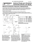
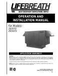
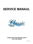
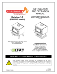
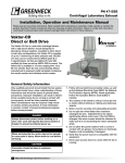
RETAIN THESE INSTRUCTIONS FOR FUTURE REFERENCE
Part # 461006
MODEL PVF
INDIRECT GAS FIRED FURNACES FOR ENERGY RECOVERY UNITS
Installation, Operation and Maintenance Manual
R
Refer to Part Number 460945 for any unit information other than that pertaining to the Indirect Fired Furnace.
WARNING!!!
Improper installation, adjustment, alteration, service or maintenance can cause injury or death.
Read the installation, operating and maintenance instructions thoroughly before installing or
servicing this equipment.
CAUTION!!!
Units are designed for outdoor installation only. DO NOT locate units indoors.
Indirect Fired Gas Unit Installations
Units are listed for installation in the United States and Canada
• Installation of gas fired duct furnaces must conform with local building codes. In the absence of local
codes, installation must conform to the National Fuel Gas code, ANSI Z223.1 or in Canada,
CAN/CGA-B149 installation codes.
• All electrical wiring must be in accordance with the regulation of the National Electric Code,
ANSI/NFPA No. 70.
• Unit is approved for installation downstream from refrigeration units. In these conditions, condensate
could form in the duct furnace and provision must be made to dispose of the condensate.
Shipping
Check the unit for shipping damage. If any shipping damage is found, it should be reported to the last carrier
and your local Greenheck representative.
®
Location Recommendations
1. Do not install units in locations where flue products
can be drawn into adjacent building openings such
as windows, fresh air intakes, etc. Distance from
vent terminal to adjacent public walkways,
adjacent buildings, operable windows, and
building openings shall conform with the local
codes. In the absence of local codes, installation
shall conform with the National Fuel Gas Code,
ANSI Z223.1, or the CAN/CGA B-149 Installation
Codes.
2. Building materials that will be affected by flue
gases should be protected.
5. Local codes may supercede any of the above
provisions.
6. Be sure that the minimum clearances to
combustible materials are maintained.
Unit Clearances to Combustible Materials
Combustion blower discharge must be located
42 in. from any combustible materials.
Venting
3. Avoid locating in an area where deep snow is likely
to accumulate. During the winter months, keep
snow clear on the access side of the unit to
prevent any blockage of combustion air inlet or
flue exhaust openings.
1. Do not modify or obstruct the combustion air inlet
cover or the combustion blower weatherhood.
4. Maintain minimum horizontal clearance of 4 feet
from electric meters, gas meters, regulators, and
relief equipment. In Canada, the minimum
clearance is 6 feet.
3. Do not add any vents other than those supplied by
the manufacturer.
2. During the winter months, periodically clear snow
from access side of unit to prevent blockage of the
inlet and exhaust openings.
Gas Connection
Gas Supply Pressure Requirements
Natural: 6 to 14 in. wg
LP: 11 to 14 in. wg
1. Single furnaces (furnace input 100 to 400 MBH)
have a single 3⁄4 inch connection. Double furnaces
(furnace input 500 to 800 MBH) have two 3⁄4 inch
connections, and triple furnaces (furnace input
1050 to 1200 MBH have three 3⁄4 inch connections.
2. When connecting the gas supply, the length of the
run must be considered in determining the pipe
size to avoid excessive pressure drop. Refer to a
Gas Engineer’s Handbook for gas pipe capacities.
3. A drip leg should be installed in the pipe run to the
unit.
4. Install an easily accessible ground joint union and a
manual shut off valve (these are required by some
local codes) for emergency shut off and easy
servicing of the controls.
7. When leak testing pressures above 14 in. wg (1⁄2 psi),
close the field installed shutoff valve, disconnect
the furnace and its gas train from the gas supply
line, and plug the supply line before testing.
8. When leak testing at pressures equal to or less than
14 in. wg (1⁄2 psi) close the field-installed shutoff
valve to isolate the unit from the gas supply line
before testing.
From
Gas
Gas Cock
Ground Joint Union
To Controls
1/8 in. Plugged
6 in. Trap
5. A 1⁄8 inch NPT plugged tap shall be installed
immediately ahead of the gas supply connection to
the furnace.
6. After gas piping is completed, carefully check all
piping connections for gas leaks. Use soap solution
or equivalent for testing. DO NOT use a flame or
other source of ignition to check for gas leaks.
2
Figure 1: Recommended Piping to Controls
Electrical Connections
WARNING!!!
•
Disconnect power supply before making wiring connections to prevent electrical shock and
equipment damage.
•
All appliances must be wired strictly in accordance with wiring diagram furnished with the unit. Any
wiring different from the diagram could result in a hazard to persons and property.
•
Any original factory wiring that requires replacement must be replaced with wiring material having a
temperature rating of at least 105°C.
1. Installation of wiring must conform with local building codes. In the absence of local codes, installation
must conform to the National Electric Code ANSI/NFPA 70-Latest Edition. Unit must be electrically
grounded in conformance with this code. In Canada, wiring must comply with CSA C22.1, Canadian
Electrical Code.
2. All furnaces are provided with a wiring diagram located on the inside of the access panel. Refer to this
wiring diagram for all wiring connections.
3. The combustion blower motor will not run unless the furnace is turned on and the gas controls are calling
for heat.
Control Center Layout
9
1
1. Two-stage temperature controls - Controls the
furnace stages based on the unit discharge
temperature.
2. Combustion blower - Exhausts the products of
combustion from the furnace tubes.
3. Ignition controller - Continually monitors,
analyzes, and controls the proper operation of
the gas burner.
2
3
4. Manifold pressure test port - Used for checking
the manifold gas pressure.
5. Time Delay relay - Allows burner to stay at high
fire for 10 seconds upon being lit.
4
6. Air pressure switch - Tests to ensure the
combustion blower is operating.
5
6
7. Two-stage gas valve - Contains main pressure
regulator, safety shut-off valves, and manual
shut off knob. It controls the furnace to 50% or
100% fire.
8. Ignitor - Provides spark for burner ignition.
7
9. Flame Sensor - Ensures that each burner has
ignited.
8
Figure 2: Furnace Control Center
3
Start-Up Procedure
1. Turn off power to the unit at the disconnect switch.
Close all manual gas valves.
2. Check that all gas and electrical connections are
weatherized.
3. Make sure that the combustion air inlet and the
combustion blower discharge are free from
obstructions.
4. Inspect the unit to make sure that no damage has
occurred during installation.
5. With the furnace control center access panel
removed, connect a “U” tube manometer to the
manifold pressure test port as shown in Figure 2.
This will be used for checking the manifold gas
pressure.
6. Set the thermostat or discharge temperature
controls to lowest setting.
Sequence of Operation
Power-up/Standby
After power is supplied to the unit:
1. The ignition control will reset and perform a selfcheck routine.
2. The diagnostic LED will flash for up to four
seconds.
3. The ignition control will begin scanning the
thermostats.
Heat Mode
When the thermostat or discharge temperature
controls call for heat:
1. The ignition control will check that the pressure
switch for the combustion blower is open.
2. The combustion blower will be energized and the
15-second pre-purge begins.
3. The gas valve is energized and the igniter will spark
for up to 10 seconds.
Natural Gas - If a flame is not sensed during the
trial for ignition, two additional trials will be
attempted before going into lockout for one hour.
LP Gas - If a flame is not sensed during the trial for
ignition, the control will go into lockout for one
hour.
4. When a flame is sensed, sparking stops
immediately. The gas valve and combustion blower
remain energized.
4
7. Open all manual gas valves including the
combination gas valve and turn power on.
8. Call for heat with the thermostat or discharge
temperature controls and allow the burner to light.
Greenheck duct furnaces are equipped with an
automatic spark ignition system which
automatically lights the burner. DO NOT attempt to
light the burners manually.
9. After the burner is lit, check to make sure that the
supply blower is operating.
10.Verify that the gas controls sequence properly (see
Sequence of Operation below).
11.Check the manifold gas pressure (see Burner
Adjustments on pages 5 and 6).
5a. Two-stage control: The burner will light at 100%
fire and remain there for 10 seconds. The
thermostat will then operate the burners at high or
low fire, depending on the demand for heat.
5b. Electronic Modulation - The burner will light at
100% fire and remain there for 10 seconds. The
main burner gas valve will then modulate from
100% down to 50% as needed. If the burner
remains on low fire for an extended period of time,
the burner will shut off and re-light as necessary.
6. The ignition control constantly monitors the
thermostat, pressure switch, and burner flame to
assure proper operation.
7. When the thermostat or discharge temperature
controls are satisfied, the main valve is deenergized and the combustion blower shuts off
following a 30-second post-purge period.
Recovery from Lockout
The ignition control will automatically reset after 1 hour
if the thermostat is still calling for heat. Prior to 1 hour,
a manual reset (cycle power to unit) is required. The
thermostat may be reset or the power interrupted for a
period of 5 seconds. See page 7 for Ignition Control
Diagnostics.
Performance Data
Air Temperature Rise Through Unit (°F)
Model
Number
PVF 100
PVF 150
PVF 200
PVF 250
PVF 300
PVF 350
PVF 400
Input Output 20
25
30
35
40
(MBH) (MBH)
100
80
3704 2963 2469 2116 1852
150
120 5556 4444 3704 3175 2778
200
160 7407 5926 4938 4233 3704
250
200 9259 7407 6173 5291 4630
300
240 11111 8889 7407 6349 5556
350
280 12963 10370 8642 7407 6481
400
320 14815 11852 9877 8466 7407
45
50
1646 1481
2469 2222
3292 2963
4115 3704
4938 4444
5761 5185
6584 5926
55
CFM
1347
2020
2694
3367
4040
4714
5387
60
65
70
75
80
85
90
95
100
1235
1852
2469
3086
3704
4321
4938
1140
1709
2279
2849
3419
3989
4558
1058
1587
2116
2646
3175
3704
4233
988
1481
1975
2469
2963
3457
3951
926
1389
1852
2315
2778
3241
3704
871
1307
1743
2179
2614
3050
3486
823
1235
1646
2058
2469
2881
3292
780
1170
1559
1949
2339
2729
3119
741
1111
1481
1852
2222
2593
2963
Ratings shown are for elevations up to 2000 ft. For higher elevations, the input should be reduced by 4% per 1000 ft. of
elevation above sea level. In Canada, from 2000 to 4500 ft in elevation, the unit must be derated to 90% of the input listed
above. The unit shall also be used in accordance with standard CGA 2.17.
Furnace Controls
Staged Temperature Controls
For Energy Recovery Units without Temperature Control Package
The furnace stage controls are located in the furnace control center. One control is
provided for each stage of heating. The discharge temperature setting is located on
the control furthest to the left. The offset and differential settings for each stage are
preset at the factory; however, field-adjustments may be made to get the best control
for your application. See the literature provided with the controls for further
information.
For Energy Recovery Units with Temperature Control Package
If two-stage control is ordered with a Temperature Control Package, the controller in
the unit’s main control center will control the stages of heating. The temperature set
point may be adjusted on the controller (See Temperature Controller IOM).
Figure 3: Staged Controls
Staged Burner Adjustments
Setting Manifold Pressure for Two Stage Gas Control
1. Set the unit to high fire by setting the
discharge temperature control or
thermostat to its maximum setting. If the
ambient temperature is warm, the unit
may not stay at high fire.
Solenoid
High Fire Adjustment
Low Fire Adjustment
High Fire
Terminal
2. Measure the burner manifold pressure at
the manifold pressure test port (see
Control Center Layout on page 3) using a
“U” tube manometer. The pressure on
high fire should be 3.5 in. wg for natural
gas and 10 in. wg for LP gas. To change
the pressure, adjust the regulator
adjustment screw on the combination gas
valve.
3. Set the unit to low fire by removing the
wire from the high fire terminal on the
combination gas valve.
4. The manifold pressure on low fire for natural gas
should be 0.88 in. wg and 2.5 in. wg for LP gas. To
change the pressure, use the low fire adjustment
screw on the combination gas valve.
Figure 4: Combination Gas Valve
5
Electronic Modulation Temperature Controls
For Energy Recovery Units without Temperature
Control Package
A Discharge Temperature Dial is used for temperature
control for electronic modulation. The temperature dial
will be located in the furnace control center.
For Energy Recovery Units with Temperature Control
Package
The Temperature Controller in the unit’s main control
center will provide the electronic modulation control.
High and Low Fire Settings for Electronic Modulation
Check the high and low gas pressures on initial start up per the instructions below. These settings are pre-set at
the factory, but should be adjusted in the field if necessary. Set the high fire first and the low fire second. The low
fire must always be checked if the high fire is changed.
Modulating Valve
Low fire adjustment
B
Combination Gas Valve
High fire adjustment
Figure 5: Electronic Modulation Valves
A
1. Set the unit to high fire by placing a jumper between terminals 7 and 8 on the Maxitrol amplifier.
2. Measure the burner manifold pressure at each furnace at the pressure test port (see Figure 2) using a high
quality manometer that can measure low gas pressures. The pressure at high fire should be 3.5 in. wg for
natural gas and 10.0 in. wg for LP Gas. To change the pressure, adjust the high fire screw on the combination
gas valve.
3. To get the unit to low fire: Remove the wire from terminal 3 on the amplifier and isolate it from touching
anything. Set the discharge temperature selector to the highest setting. If there is a room override thermostat,
turn the dial to the highest setting.
4. Measure the manifold pressure on low fire, it should be 0.88 in. wg for natural gas and 2.5 in. wg for LP gas.
5. To adjust the low fire, remove the bypass cap (A) and turn screw (B) as shown in diagram. Adjust the screw
indicated in Figure 5 on the modulating valve.
6. Reconnect wire to terminal 3.
7. Remove jumper and place all wires back to where they were and plug the manifold pressure port.
6
Troubleshooting
Ignition Control Diagnostic LED
During normal operation, the LED is shut off. The LED
will be on or flashing during a fault condition. If a fault
condition is occurring, turn the unit off and on again. If
the LED is still flashing, refer to the following
troubleshooting section.
LED Indication
Steady on
1 flash
2 flashes
3 flashes
Error Mode
Internal control failure
Air flow fault
Flame with no call for heat
Ignition lockout
Airflow Fault (1 Flash)
An airflow fault may occur for the following reasons:
• An airflow switch continually monitors the combustion airflow during an ignition sequence. During the initial
call for heat, if the pressure switch contacts are in the closed position for 30 seconds without an output to
the combustion blower, an airflow fault will be declared. The control will remain in this mode with the
combustion blower off.
• After the combustion blower output (L1 and IND) is energized and the airflow switch remains open for more
than 30 seconds, an airflow fault will be declared. The control will stay in this mode with the combustion
blower on, waiting for the airflow switch to close.
• If the airflow signal is lost while the burner is firing, the control will immediately de-energize the gas valve
and the combustion blower will remain on. If the call for heat remains, the control will wait for proper airflow
to return. If proper airflow is not detected after 30 seconds, an airflow fault will be declared. If proper airflow
is detected at any time, a normal ignition sequence will begin.
Once proper airflow is detected, the normal Sequence Of Operation for ignition will follow (see page 4).
Flame Fault (2 Flashes)
If the main valve fails to close completely and maintains a flame, the full-time flame sense circuit will detect it and
energize the combustion blower. Should the main valve later close completely and remove the flame signal, the
combustion blower will be de-energized.
Ignition Lockout (3 Flashes)
Possible Cause
Solution
Manual gas valve not open
Open manual valve
Air in the gas line
Bleed gas line
Supply gas pressure too high or too low
Check that supply pressure is between 6 in. wg and 14 in. wg for
natural gas and 11 in. wg and 14 in. wg for LP.
Loose wire connections
Check for tight wire connections.
No spark:
a. Transformer failure
a. Check primary and secondary voltages of transformer. Replace
if necessary.
b. Spark electrode
b. Ensure spark gap is 1⁄8 in. and ceramic insulator is not cracked.
Replace if necessary. Electrode is NOT field-adjustable.
c. Spark cable shorted to ground
c. Replace spark cable
d. Ignition controller not grounded
d. Check that the ignition controller is grounded to the furnace
control center.
High limit control tripped
Check unit airflow and manifold pressure.
Faulty combination gas valve
If 24 volts is measured between terminals MV and common, but
valve remains closed, replace valve.
Faulty ignition control
Check diagnostic LED for steady on and for voltage between V1
and V2. If no voltage is present, replace ignition control.
7
Routine Maintenance
CAUTION!!!
Turn off all gas and electrical power to the unit before performing any maintenance or
service operations to this unit.
Combustion Blower Motor
Motor maintenance is generally limited to cleaning.
Cleaning should be limited to exterior surfaces only.
Removing dust and grease build-up on the motor
housing assures proper motor cooling. Use caution
and do not allow water or solvents to enter the motor
or bearings. Under no circumstances should motors or
bearings be sprayed with steam, water or solvents.
The motor bearings are pre-lubricated and sealed,
requiring no further lubrication.
Burners and Orifices
Before each heating season, examine the burners and
gas orifices to make sure they are clear of any debris
such as spider webs, etc. Clean burner as follows:
• Turn off both electrical and gas supplies to the
unit.
• Disconnect union between manifold and gas
valve.
• Remove manifold and burner assembly.
• Inspect and clean orifices and burners as
necessary. Avoid using any hard or sharp
instruments which could cause damage to the
orifices or burners.
- Remove any soot deposits from the burner
with a wire brush.
- Clean the ports with an aerosol degreaser
or compressed air.
- Wipe the inside of the burner clean.
Cleaning the burner with a degreaser will
slow the future buildup of dirt.
• Before reinstalling the burner assembly, look
down the heat exchanger tubes to make sure
they are clear of any debris.
• Reinstall manifold and burner assembly,
reconnect wire leads, and gas supply piping.
• Turn on the electrical power and gas supply.
• Follow the start-up procedure to light the
burners and verify proper operation.
Heat Exchanger
The heat exchanger should be checked annually for
cracks and discoloration of the tubes. If a crack is
detected, the heat exchanger should be replaced
before the unit is put back into operation. If the tubes
are dark gray, airflow across the heat exchanger
should be checked to make sure the blower is
operating properly.
Flue Collector Box
The flue passageway and flue collector box should be
inspected prior to each heating season and cleared of
any debris.
Electrical Wiring
The electrical wiring should be checked annually for
loose connections or wiring deterioration.
Replacement Parts
When ordering replacement parts, include the
complete unit model number and serial number listed
on the unit rating plate.
Warranty
Greenheck warrants this equipment to be free from defects in material and workmanship for a period of one
year from the purchase date. Any units or parts which prove to be defective during the warranty period will
be repaired or replaced at our option.
The motor is warranted by the motor manufacturer for a period of one year. Should the motor prove
defective during this period, it should be returned to an authorized motor service station.
Greenheck will not be responsible for any installation or removal costs.
Copyright © 2001 Greenheck Fan Corp.
ERCH - PVF IOM FS
Rev1 July 2001