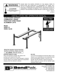
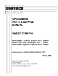
1
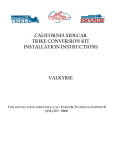
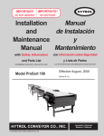
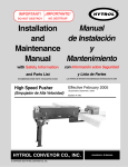
GRAVELY
NAME: GRAVELY SNOWBLOWERS
OPERATOR'S
MANUAL
PART NUMBER(S):
28”
34”
38”
44”
- 20979
- 20981
- 20980
- 20982
The 28 Inch and 34 Inch Snowblowers are used with Gravely two wheel tractors. The 38 Inch and 44
Inch Snowblowers are used with Gravely four wheel tractors.
To fasten the Snowblower to a Gravely two wheel tractor a Quick Hitch Pin Kit, part No. 23220, is
needed. To fasten the Snowblower to a Gravely four wheel tractor a Front Drive Kit, part No. 21124, is
needed.
All reference to left side, right side, front and rear are from the operator's position.
To continue its program of quality and design improvement,
the manufacturer reserves the right to change specifications,
designs and prices without notice and incurring obligation.
Form No: 24729 (6-78)
Printed in U.S.A.
CONTENTS
1.0 ....................................................SAFETY PRECAUTIONS
2.0 ....................................................ILLUSTRATED PARTS LIST
3.0 ................................................... CONNECTING THE SNOWBLOWER TO THE
TWO WHEEL TRACTOR
4.0 ....................................................OPERATING THE 28 or 34 INCH
SNOWBLOWER
5.0 ................................................... CONNECTING THE SNOWBLOWER TO THE
FOUR WHEEL TRACTOR
6.0 ................................................... OPERATING THE 38 or 44 INCH
SNOWBLOWER
7.0 ....................................................MAINTENANCE
8.0 ....................................................STORAGE
1.0 SAFETY PRECAUTIONS
The information in this Operator's Manual must be followed to do service
and for safe operation of this equipment.
Using this equipment the wrong way can cause injury to persons and
damage to the equipment. Persons using or doing maintenance on this
equipment must read this Operator's Manual and follow the instructions.
It is important to understand that the warnings in this Operator's Manual
and any other instruction book do not list every possible danger. It is not
possible for Gravely to know and tell the operator or person doing service on the
equipment of all the dangers in operating and doing service an the equipment.
The purchaser must give these instructions to the persons operating and
doing maintenance on this equipment. The purchaser must get the operator and
person doing maintenance on this equipment to use eye and foot protection.
1.1
TRAINING
1. Read the Operator's Manual and learn the
function of the tractor's controls. Know how to
stop the tractor and snowblower drive fast.
2. Never let children operate the equipment.
3. Let adults operate the equipment only after
reading and understanding the instructions in
this Operator's Manual.
1.2
PREPARATION
1. Before snowfall, inspect the area of operation
and remove all material that will be thrown, stop
or do damage to the snowblower.
2. Put 'the Direction Control lever in the neutral
position and the PTO control in the OFF position
before starting the engine.
6. Vibration or sound change is a warning that
damage has been done. Make repairs before
operating the equipment.
7. Never start and run the engine inside a building
except to move the equipment outside.
8. The snowblower auger or impeller can be
stopped by too much ice, snow or debris while
the engine is still giving power to the
snowblower. Severe injury to the person can be
caused when cleaning the snowblower while the
engine is running. NEVER CLEAN THE
SNOWBLOWER
WITH
THE
ENGINE
RUNNING.
3. Use foot protection that will decrease sliding.
9. When removing snow from a slope, go up and
down the slope, never across.
4. Use caution when putting gasoline in the fuel
tank.
10. Use caution when changing direction on
slopes.
5. Use a clean and tight fuel container.
11. Never operate the snowblower without all safety
equipment being in place.
6. Never put gasoline in the fuel tank while the
engine is running.
7. Never put gasoline in the fuel tank while the
tractor is inside a building.
8. Clean off any gasoline that falls on the tractor
before starting the engine.
9. Lower the snowblower skids to give ground
clearance needed to stop gravel from going into
the snowblower.
1.3
5. After hitting some material, put the PTO control
in the OFF position and turn the ignition switch
to the OFF position_ Make repairs before
restarting.
OPERATION
1. Keep away from moving parts.
2. Keep away from the discharge chute.
3. Never use the tractor for person transport.
4. Put the PTO control in the OFF position, turn
the ignition switch to the OFF position and wait
until the engine and moving parts stop before
leaving the tractor seat or operator's position to
make adjustments, repairs, or give service.
12. Discharge the snow away from any area
where the snow can cause damage.
13. The forward speed must be slow enough to
permit the snow to go through the snowblower without being stopped.
14. Use a slow speed when moving the equipment to
decrease sliding on surfaces with ice.
15. Use only Gravely accessories for the snowblower and tractor.
16. Do not operate unless you can check the area
visually.
17. Run the snowblower a short time after
blowing snow to decrease freezing of the
collector/impeller.
18. After using the snowblower, disengage the PTO
and stop the engine and remove all snow and
ice before putting the snow-blower in
storage.
19. Never put the tractor in storage with gasoline
in the fuel tank.
SNOWBLOWERS, 28”, 34", 38" & 44"
FAN DRIVE
SNOWBLOWERS, 28", 34", 38" & 44"
FAN DRIVE
ITEM NO.
1
2
3
4
5
6
7
8
9
10
11
12
13
14
15
16
PART NO.
419454
180044
20992
124553
20573
12134
14987
19731
19741
24560
20859
19740
21168
411027
20727
20728
QTY.
2
1
1
1
1
1
4
1
1
1
2
1
1
1
1
1
DESCRIPTION
Nut, Lock; 1/4-20 Washer Insert
Bolt, Hex; 1/4-20 x 2
Weldment, Drive Shaft
Key, Woodruff; 1/4 x 1 Hard No. 15
Kit, Repair Universal Joint Neapco 1605x
Kit, Repair Universal Joint Rockwell Std.
Ring, Retaining; 1.00 Shaft
Weldment, Fan
Bearing, Ball; 1.000 x 1.850 x .472
Kit, Repair Universal Joint (Neapco)
Ring, Retaining
Support
Assembly, U--Joint; Double; Applies to 28" & 34" Only
Fitting, Lube; 1/4-28 Lube; 1/4-28
Joint, Universal; Rect. Shaft
Joint, Universal; Rect. Tube
Refer to Reel Drive Assembly
NOTE: Circle A Pertains to 38" & 44" Riding Snowblowers Only
SNOWBLOWERS, 28", 34", 38" & 44"
CRANK ASSEMBLY
ITEM NO.
PART NO.
QTY.
1
2
3
4
5
6
7
8
9
10
11
12
13
14
15
16
20984
20999
19340
20989
456542
21144
20997
20998
9630
9612
10211
120396
137185
21005
21020
9652
21022
454563
10210
20985
1
1
1
1
2
1
1
1
2
1
1
1
1
1
1
1
1
1
1
1
17
18
19
DESCRIPTION
Bracket, Support
Spring, Compression
Race, Bearing Thrust; 1.002 x 1.552 x .030
Shaft
Pin, Spring; 3/16 x 1-1/2
Eye, Single
Assembly, Cable
Support
Clamp, Hose SAE; Type F
Connector
Grip, Handle
Washer, Flat; .500 x 1.062 x .095
Pin, Cotter; .125 x 1.00
Weldment, Crank Support; 38" & 44"
Decal, Snowblower Discharge
Crank, 28" & 34" Snowblower
Crank, 38" & 44" Snowblower
Pin, Spring; 3/16 x 7/8 Cap
Cap, Stud
Weldment, Crank Support; 28" & 34"
SNOWBLOWERS, 28", 34", 38" & 44"
REEL DRIVE ASSEMBLY
SNOWBLOWERS, 28”, 34”, 38” & 44”
REEL DRIVE ASSEMBLY
ITEM NO.
1
2
3
4
5
6
7
8
9
10
11
12
13
14
15
16
17
18
19
20
21
22
23
24
25
26
27
28
29
30
31
32
PART NO.
QTY.
120392
6341
6339
9660
9659
20696
10325
9662
9661
20697
6485
11796
19794
103880
426767
10573
9668
12399
9657
181666
9667
12404
12401
12402
12403
274655
10579
120423
9669
12400
20699
10222
11797
19795
20698
10221
11802
19799
6494
6493
4
1
1
2
1
1
1
2
1
1
1
1
1
1
2
1
2
2
2
2
1
2
1
1
1
2
1
3
1
1
1
1
1
1
1
1
1
1
1
2
DESCRIPTION
Washer, Flat; .281 x .625 x .065
Cap, Front Pinion Bearing
Gasket, Bearing Cap
Bearing, Torrington; B-128 (B-128-OH)
Washer, Thrust
Shaft, Snowblower Worm
Spacer
Bearing, Needle Thrust Race
Bearing, Torrington #NTG-1427
Shaft, 28 In. Reel
Shaft, 34 In. Reel
Shaft, 38 In. Reel
Shaft, 44 In. Reel
Plug, Pipe; 1/2 In. SQ HD Steel
Nut, Hex; 7/8-14
Housing, Snowblower; Gear
‘O' Ring; 1-3/4 x 2-1/8 x 3/16
Plate, Drive
Disc, Friction
Bolt, Hex; 7/16-20 x 1
Seal, Oil; 3/4 x 1.851 x 3/8
Bearing, Thrust Race Torr TRD-2840
Gear, Worm
Tube, Reel Gear
Key
Nut, Lock; 7/16-20 Type N Hex
Bracket, Gear Box Support
Washer, Lock; 1/4 Int. Tooth
O'Ring; 3 x 3-1/4 x 1/8
Cap, Gear Housing
Reel, Weldment; 28 In. R. H.
Reel, Weldment; 34 In. R. H.
Reel, Weldment; 38 In. R. H.
Reel, Weldment; 44 In. R. H.
Reel, Weldment; 28 In. L. H.
Reel, Weldment; 34 In. L. H.
Reel, Weldment; 38 In. L. H.
Reel, Weldment; 44 In. L. H.
Washer, Pilot
Washer, Belleville Spring; 1-1/4 x 2-1/2
NOTE: Items shown in Circle "A" pertains to 38” & 44” Riding Snowblowers Only
SNOWBLOWERS, 28" & 34"
FRAME ASSEMBLY
SNOWBLOWERS, 28" & 34" WALKING
FRAME ASSEMBLY
ITEM NO.
1
2
3
4
5
6
7
8
9
10
11
12
13
14
15
16
17
18
19
20
21
22
23
24
25
26
27
22
29
30
31
32
33
34
35
36
37
38
39
40
41
42
43
44
45
46
47
48
49
50
51
52
53
PART NO.
180075
12409
10579
120394
456004
20706
6412
20707
6396
180020
419455
419454
413447
126485
180080
120392
180122
120518
6477
435507
120396
24379
180177
20703
20722
19479
20994
6404
10580
445339
20928
164354
6370
6496
180016
120622
6352
10496
21244
155886
120380
6464
6399
6381
19740
180130
20984
180124
20998
180175
20708
180021
21020
20985
19297
126348
QTY.
5
2
I
13
9
1
1
1
1
2
4
13
5
4
4
11
4
4
2
8
4
2
1
1
1
2
1
1
4
4
2
4
1
1
1
3
I
I
I
3
I
1
1
1
1
2
1
3
1
4
I
3
1
1
1
2
DESCRIPTION
Bolt, Hex; 5/16-18 x 5/8
Bearing, Flange
Bracket, Gear Box Support
Washer, Flat; .406 x .812 x .065
Nut, Lock; 3/2-16 Washer Insert Hex
Strip, Wear; 28 In.
Strip, Wear; 34 In.
Guard, Snowblower 28 In.
Guard, 34 In.
Bolt, Hex; 1/4-20 x 3/4
Nut, Lock; 5/16-18 Washer Insert Hex
Nut, Lock; 1/4-20 Washer Insert Hex
Nut, Lock; 5/16-18 Type N Hex
Bolt, 1/2-13 x 1-1/4 RD HD SQ NK
Bolt, Hex; 5/16-18 x 1-1/8
Washer, Flat; .281 x .625 x .065
Bolt, Hex; 3/8-16 x 1
Bolt, 1/4-20 x 3/4 RD HD SQ NK
Ring, Bearing
Nut, Lock; 1/2-13 Washer Insert Hex
Washer, Flat; .500 x 1.062 x .095
Skid
Bolt, Hex; 1/2-13 x 1-1/2
Weldment, Body; 28 In. Snowblower
Weldment, Body; 34 In. Snowblower
Decal, Caution
Weldment, Fan Housing
Chute, Weldment
Glide
Nut, Spring Shape 8032 Type A-J
Spacer, Tube Guard
Screw, Tapping 8-32 x 3/8 Pan Head Type C
Guide, Cable Weldment
Clamp
Bolt, Hex; 1/4-20 x .50
Nut, Mach; 8-32 Hex
Baffle, Deflector
Retainer, Baffle
Pin, Self-Locking
Screw, Mach; 8-32 x 1/2 Flat Hd C-Recess
Washer, Lock; 1/4 SP
Wing, Deflector
Chute, Deflector Weldment
Rope, Wire
Support
Bolt, Hex; 3/8-16 x 2
Bracket, Support
Bolt, Hex; 3/8-16 x 1-1/4
Support
Bolt, Hex; 1/2-13 x 1.25
Support, Weldment
Bolt, Hex; 1/4-20 x 7/8
Decal, Snowblower Discharge
Crank, Support Weldment
Bushing; .531 x 1.000 x .600
Bolt, 1/4-20 x 2-1/4 RD HD SQ NK
SNOWBLOWERS, 38" & 44"
FRAME ASSEMBLY
SNOWBLOWERS, 38" & 44"
FRAME ASSEMBLY
ITEM NO.
PART NO.
QTY-
1
2
180075
11788
19791
10579
120394
456004
180020
11789
19792
12409
126485
120518
419454
419455
413447
180080
19479
435507
120396
180122
120392
24379
6477
126348
10580
445339
20994
6404
164354
20928
6370
6496
180016
120622
6352
10496
155886
120380
6464
6399
11809
6381
180175
19740
20984
10405
131017
180124
21020
180130
21008
20998
20726
20732
21005
180021
5
1
1
1
13
9
2
1
1
2
4
4
12
4
5
4
2
8
4
4
8
2
2
2
4
4
1
1
4
2
1
1
1
3
1
1
3
1
1
1
1
1
4
1
1
1
1
3
1
2
1
1
1
1
1
3
3
4
5
6
7
8
9
10
11
12
13
14
15
16
17
18
19
20
21
22
23
24
25
26
27
28
29
30
31
32
33
34
35
36
37
38
39
40
41
42
43
44
45
46
47
48
49
50
51
52
53
DESCRIPTION
Bolt, Hex; 5/16-18 x 5/8
Strip, Wear
Strip, Wear
Bracket, Gear Box Support
Washer, Flat; .406 x .812 x .065
Nut, Lock; 3/8-16 Washer Insert Hex
Bolt, Hex; 1/4-20 x 3/4
Guard
Guard
Bearing, Flange
Bolt; 1/2-13 x 1-1/4 RD HD SQ NK
Bolt; 1/4-20 x 3/4 RD HD SQ NK
Nut, Lock; 1/4-20 Washer Insert Hex
Nut, Lock; 5/16-18 Washer Insert Hex
Nut, Lock; 5/16-18 Type N Hex
Bolt, Hex; 5/16-18 x 1-1/8
Decal, Caution
Nut, Lock; 1/2-13 Washer Insert Hex
Washer, Flat; .500 x 1.062 x .095
Bolt, Hex; 3/8-16 x 1
Washer, Flat; .281 x .625 x .065
Skid
Ring, Bearing
Bolt, 1/4-20 x 2-1/4 RD HD SQ NK
Glide
Nut, Spring Shape 8032 Type A-J
Weldment, Fan Housing
Chute, Weldment
Screw, Tapping 8-32 x 3/8 Pan Head Type C
Spacer, Tube Guard
Guide, Cable Weldment
Clamp
Bolt, Hex; 1/4-20 x .50
Nut, Mach; 8-32 Hex
Baffle, Deflector
Retainer, Baffle
Screw, Mach; 8-32 x 1/2 Flat HD C-Recess
Washer, Lock; 1/4 SP
Nut, Deflector Wing
Chute, Deflector Weldment
Rod, Push Weldment
Rope, Wire
Bolt, Hex; 1/2-13 x 1.25
Support
Bracket, Support
Cotter, Hair Pin
Washer, Flat; .812 x 1.469 x .134
Bolt, Hex; 3/8-16 x 1-1/4
Decal, Snowblower Discharge
Bolt, Hex; 3/8-16 x 2
Weldment, Support
Support
Weldment, Body; 38 In. Snowblower
Weldment, Body; 44 In. Snowblower
Weldment, Crank Support
Bolt, Hex; 1/4-20 x 7/8
3.0 CONNECTING THE SNOWBLOWER TO
THE TWO WHEEL TRACTOR
1. Install the Quick Hitch Pin Kit as shown
in figure 3.0-1.
8. Put the ring pin through the hole in the end of the
quick hitch pin as shown in figure 3.0-2.
f
1 -Quick Hitch Pin
2 - Bolt
3 -Attachment Adapter
4 --- Bushing
Figure 3.0-1
2. Put the bushing on the 1/2" x 2-3/4" Bolt
and fasten to the upper, left quick hitch
stud as shown in figure 3.0-1.
3. Apply multi-purpose grease to the quick
hitch pin and power take-off (PTO) shaft
on the tractor.
4. Put the universal joint on the snowblower drive shaft as far as it will go.
5. Move the tractor putting the quick hitch
pin three and one half inches into the
snowblower support.
6. Put the other end of the universal joint
on the PTO shaft of the tractor.
7. Move the tractor putting the quick hitch
pin all the way through the snowblower
support.
1 - Ring Pin
2 -Snowblower Support
3 -Universal Joint
Figure 3.0-2
To remove the snowblower from the tractor,
remove the ring pin. Separate the tractor and
snowblower and keep the universal joint with
the snowblower.
4.0 OPERATING THE 28 & 34 INCH
SNOWBLOWERS
Read the tractor Operator's Manual. Know how to
operate the tractor controls.
1. Adjust the skids shown in figure 4.0-1 to
give ground clearance needed for the
surface conditions. When removing snow
from a gravel surface, adjust the skids to
raise the snowblower to prevent gravel from
going into the snowblower. When removing
snow from a smooth surface, the
snowblower can be lowered until the
wearstrip contacts the surface.
1 - Deflector Chute
2 - Wing Nut
Figure 4.0-2
1 -Skid
2 - Bolt
1 -Discharge Chute Crank
Figure 4.0-1
2. Adjust the deflector chute by loosening the
wing nut shown in figure 4.0-2. The deflector chute controls the distance the snow
will be blown.
3. Start the tractor engine. Wait until the
engine is smooth running before operating
the snowblower.
4. Push the discharge chute crank in and turn
the crank to rotate the discharge chute to a
position that snow will be blown away. See
Figure 4.0-3.
Figure 4.0-3.
5. If the tractor has a Range Shift, put it in the
LOW position.
6. Engage the PTO.
7. Move the throttle lever to the FAST position.
8. Put the Gear Shift in the LOW position.
NOTE: When going through the snow for the first
time, a full width passage must be cut. The
forward speed must be slow enough to permit
the snow to go through the discharge chute
without being stopped.
5.0 CONNECTING THE SNOWBLOWER TO THE FOUR
WHEEL TRACTOR
1. Install the front drive kit on the tractor.
See figure 5.0-1.
9. Put the Direction Control Lever in the forward
position and make the first passage through
the snow.
WARNING:
The snowblower auger or impeller can be
stopped by too much ice, snow or debris while
the engine is still giving power to the snowblower. Severe injury to the person can be
caused when cleaning the snowblower while the
engine is running.
NEVER CLEAN THE SNOWBLOWER WITH THE
ENGINE RUNNING.
10. On the next and remaining passages, cut as
much snow as will go through the discharge
chute without being stopped.
11. If the reel stops turning while the fan
continues to turn, disengage the PTO, stop
the engine and tighten the nuts on each end
of the reel shown in figure 4.0-4 to a torque of
85 ft. lbs. (115 Nm).
1 - Reel
2 - Nut
Figure 5.0-1
2. Fasten the universal joint tube to the snowblower drive shaft with the 1/4" x 2" bolt and
1/4" lock nut as shown in figure 5.0-2.
1 - Universal Joint Tube
2 - Bolt
Figure 4.0-4
Figure 5.0-2
3. Put the frame pivot rod of the snowblower
support in the front attachment brackets
and fasten with the hitch pins as shown
in figure 5.0-3.
1.
2.
3.
4.
5.
Frame Pivot Rod
Front Attachment Bracket
Hitch Pin
Universal Joint Shaft
Universal Joint Tube
Figure 5.0-3
4. Put the universal joint shaft into the
universal joint tube and put the universal
joint shaft on the drive shaft of the front
drive kit as shown in figure 5.0-3.
5. Put the snowblower push rod on the snowblower support and fasten with the hitch
pin. Then put the front drive kit push
rod in the snowblower push rod.
6. Put the front drive kit push rod pivot pin
in the top hole in the attachment lift on
the tractor and fasten with the hitch
pin as shown in figure 5.0-4.
1.
2.
3.
4.
Front Drive Kit Push Rod
Snowblower Push Rod
Front Drive Kit Push Rod Pivot Pin
Hitch Pin
Figure 5.0-4
6.0 OPERATING THE 38 & 44 INCH
SNOWBLOWERS
Read the tractor Operator's Manual. Know how to
operate the tractor controls.
1. Adjust the skids shown in figure 6.0-1 to
give ground clearance needed for the
surface conditions. When removing snow
from a gravel surface, adjust the skids to
raise the snowblower to prevent gravel from
going into the snowblower. When removing
snow from a smooth surface, the
snowblower can he lowered until the
wearstrip contacts the surface.
I - Discharge Chute Crank
Figure 6.0-2.
7. Engage the PTO.
8. Move the throttle lever to the FAST position.
9. Put the GEAR selector in the 2 position.
NOTE: When going through the snow for the
first time, a full width passage must be cut.
The forward speed must be slow enough to
permit the snow to go through the discharge chute without being stopped.
1 – Skid
2 – Bolt
Figure 6.0-1
2. Adjust the deflector chute by loosening the
wing nut shown in figure 4.0-2. The deflector chute controls the distance the snow
will be blown.
3. Start the tractor engine. Wait until the
engine is
4. Push the discharge chute crank in and turn
the crank to rotate the discharge chute to a
position that snow will be blown away from
the area that is being cleaned. See figure
6.0-2.
5. Lower the snowblower to the ground.
6. Put the RANGE selector in the LO
position.
10. Put the Direction Control Lever in the forward position and make the first passage
through the snow.
WARNING:
The snowblower auger or impeller can be
stopped by too much ice, snow or debris while
the engine is still giving power to the snowblower. Severe injury to the person can be
caused when cleaning the snowblower while
the engine is running.
NEVER CLEAN THE SNOWBLOWER WITH THE
ENGINE RUNNING.
11. On the next and remaining passages, cut as
much snow as will go through the discharge
chute without being stopped.
12. If the reel stops turning while the fan continues
to turn, disengage the PTO, stop the engine and
tighten the nuts on each end of the reel shown in
figure 6.0-3 to a torque of 85 ft. lbs. (115 Nm).
8.0 STORAGE
1. Clean the Snowblower.
1. Check the gear housing lubricant level by
removing the pipe plug shown in figure 8.0-I.
The lubricant level is correct when the lubricant
is at the bottom of the pipe plug hole. Add SAE
90W EP gear lubricant when the level is low.
Install the pipe plug and tighten it.
2. To prevent rust, put paint or grease on any area
where the paint has been removed.
1 - Reel
2 – Nut
Figure 6.0-3
7.0 MAINTENANCE
After Each Use
1. Inspect all nuts, bolts and other fasteners to
make Insp sure they are tight and replace any
that are gone.
2. Inspect the reel, fan, skids and wearstrip for
damage and replace if damaged.
3. Put lubricant on the wire rope where it goes
through the guide tubes. Use tractor engine
lubricant.
4. Put lubricant in the holes where the fan housing
connects to the reel housing. Use tractor engine
lubricant.
5. Add multi-purpose grease to the grease fitting
on the universal joint until grease comes out the
end of the universal joint
6. tube.
1 --Gear Housing
2 - Pipe Plug
Figure 8.0-1
GRAVELY ATTACHMENT LIMITED WARRANTY
This Limited Warranty is issued by Gravely Division,
McGraw-Edison Company, and consists of the following
terms:
6.
This Warranty does not cover the following:
1.
Only the original purchaser of new Gravely
manufactured attachments is covered by this
Warranty.
a. Transportation between owner's home or place
of business and the dealership. If the dealer
provides the transportation of the attachment, he
will charge the owner his usual rate for such
service.
2.
This Warranty covers repair or replacement of parts
manufactured by Gravely which are defective in
material or workmanship. Gravely will pay for parts
and labor only.
b. Normal maintenance services and normal
replacement of items such as spark plugs, belts,
oil, oil filters, air filters, and mower, plow or
cultivator blades.
3.
The Warranty starts the date of purchase and lasts
for NINETY (90) DAYS for attachments used in
Roofer applications, and TWELVE (12) MONTHS
for products used in all other applications.
4.
Some components of Gravely attachments are not
covered by the Gravely Warranty. These
components are covered by the original
manufacturer's warranty, which is included with the
product. They are:
7.
GRAVELY MAKES NO OTHER EXPRESS
WARRANTIES.
ANY IMPLIED WARRANTIES,
INCLUDING
WARRANTIES
AS
TO
MERCHANTABILITY OR FITNESS FOR A
PARTICULAR PURPOSE, ARE LIMITED IN
DURATION TO THE PERIOD SET OUT IN
PARAGRAPH 3 ABOVE. SOME STATES DO NOT
ALLOW LIMITATIONS ON HOW LONG AN
IMPLIED WARRANTY LASTS, SO THE ABOVE
STATEMENT MAY NOT APPLY TO YOU.
8.
GRAVELY SHALL HAVE NO RESPONSIBILITY
FOR
INCIDENTAL
OR
CONSEQUENTIAL
DAMAGES RESULTING FROM THE BREACH OF
ANY WARRANTY, INCLUDING, BUT NOT
LIMITED TO, INCONVENIENCE, RENTAL OR
PURCHASE OF REPLACEMENT PRODUCTS,
LOSS OF PROFITS OR COMMERCIAL LOSSSOME STATES DO NOT ALLOW THE
EXCLUSION OR LIMITATION OF INCIDENTAL
OR CONSEQUENTIAL DAMAGES, SO THE
ABOVE LIMITATION OR EXCLUSION MAY NOT
APPLY TO YOU.
9.
This Warranty gives you specific legal rights, and
you may have other rights which vary from state to
state.
a) Engine - Honda
b) Tires - Goodyear and Armstrong
5.
To obtain warranty service on Gravely attachments
including components not manufactured by Gravely.
use this procedure.
a. Notify the Gravely dealer from whom you
purchased the attachment.
b. If you have moved and it is not convenient to
notify the selling dealer, notify the nearest
Gravely dealer. You should supply this dealer
with a copy of the bill of sale as proof of the date
of purchase.
c. Make arrangements to have the attachment
delivered to the dealer (refer to paragraph 6(a)
below.
d. It you have any questions concerning the
Gravely Limited Warranty, they should be
referred to
Gravely Division
McGraw-Edison
Company One Gravely
Lane Clemmons, NC
27012
Attn: Manager of Customer Services
e. Warranty service on Gravely attachments must
be performed by an authorized Gravely dealer or
Gravely factory branch.
10. A Gravely product registration card is supplied with
each Gravely product. Please complete the card
and return it to Gravely at the address listed on the
card. The registration card will be used by Gravely
for.
a. Recording date of purchase.
b. Notification of owners in compliance with the
Consumer Product Safety Act, should any
notification be necessary.
The return of registration card is not required in order to
take advantages of this Warranty.
11. This Warranty is not subject to change or
modification by anyone, including Gravely dealers
and no Gravely dealer is authorized to make any
representations or promises on Gravely's behalf.
GRAVELY
Gravely Division, McGraw-Edison Company
One Gravely Lane, Clemmons, NC 27012