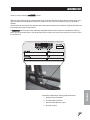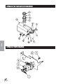
1
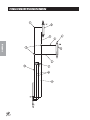
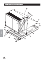
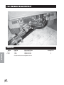
OPERATOR’S
PARTS & SERVICE
MANUAL
SWEEP STAR P48
Model 7-600-A Low Dump Hydraulic Drive P48HLD
Model 7-700-A High Dump Engine Drive
P48HE
Model 7-800-A High Dump Hydraulic Drive P48HHL
Starting Serial # P48HHL/P48HLD/P48HE - 7877
March, 2005
SMITHCO PRODUCT SUPPORT
1-800-891-9435
Hwy SS and Poplar Avenue, Cameron WI 54822
E-mail: [email protected]
Introduction
CONTENTS
Introduction ......................................... 1-10
Service
Diagrams
Parts
Accessories
Introduction ................................................................................. 1-6
Introduction ................................................................................. 1
Safe Practices ............................................................................. 2
Specifications .............................................................................. 3
Hydrauilic Drive Hose Kits ........................................................... 3
Setup .......................................................................................... 4
Operation ................................................................................ 4-7
Service ........................................................................................ 7-11
Maintenance ........................................................................... 7-8
Service Chart ........................................................................ 9-10
Troubleshooting ........................................................................ 11
Storage ..................................................................................... 11
Diagrams ...................................................................................12-19
P48HHL High Dump Hydraulic Diagram .............................. 12-13
P48HLD Low Dump Hydraulic Diagram ............................... 14-15
P48HE High Dump Engine Drive Hydraulic Diagram ......... 16-17
P48HE High Dump Engine Drive Electrical Diagram .......... 18-19
Parts ..........................................................................................20-45
P48HHL High Dump Hydraulic Drive Main Drawing ............. 20-21
P48HLD Low Dump Hydraulic Drive Main Drawing .............. 22-23
P48HE High Dump Engine Drive Main Drawing ................... 24-25
P48HHL High Dump Main Frame ......................................... 26-27
P48HLD Low Dump Main Frame ......................................... 28-29
P48HE High Dump Main Frame ........................................... 30-33
Hydraulic Oil Taank and Filter .............................................. 34-35
7-712 Hydraulic Pump .......................................................... 34-35
7-711 Manifold Valve ............................................................36-37
Reel ..................................................................................... 38-39
High Dump Hopper ..............................................................40-41
Low Dump Hopper / Tailgate ................................................ 42-43
7-833 Hydraulic Motor .......................................................... 44-45
Accessories ..............................................................................46-51
7-850 Jacobsen Truckster Hose Kit ..................................... 46-47
7-851 John Deere Pro Gator Hose Kit ................................. 48-49
7-852 Toro Workmand Hose Kit ........................................... 50-51
Reference ..................................................................................52-54
Decal List .................................................................................. 52
Declaration off Conformity ......................................................... 53
Quick Reference Replacement Parts ........................................ 54
Warranty .......................................................... Inside Back Cover
Reference
INTRODUCTION
Thank you for purchasing a
product.
Read this manual and all other manuals pertaining to the Sweep Star P48 carefully as they contain safety, operating, assembly and maintenance instructions. Failure to do so could result in personal injury or equipment
damage.
Keep manuals in a safe place after operator and maintenance personnel have read them. Right and left sides are
from the operator’s seat, facing forward.
All
machines have a Serial Number and Model Number. Both numbers are needed when ordering
parts. The serial number plate on the Sweep Star P48 is located on the front cross member of the frame next to
the cylinder arm.
Reference
For easy access record your Serial and Model numbers here.
Information needed when ordering replacement parts:
1. Model Number of machine
2. Serial Number of machine
3. Name and Part Number of part
4. Quantity of parts
1
SAFE PRACTICES
Introduction
1. It is your responsibility to read this manual and all publications associated with this machine (engine,
accessories and attachments).
2. Never allow anyone to operate or service the machine or its attachments without proper training and
instructions. Never allow minors to operate any equipment.
3. Learn the proper use of the machine, the location and purpose of all the controls and gauges before you
operate the equipment. Working with unfamiliar equipment can lead to accidents.
4. Wear all the necessary Personal Protective Equipment (PPE) to protect our head, eyes, ears, hands and
feet. Operate the machine only in daylight or in good artificial light.
5. Inspect the area where the equipment will be used. Beware of overhead obstructions and underground
obstacles. Stay alert for hidden hazards.
6. Never operate equipment that is not in perfect working order or without decals, guards, shields, or other
protective devices in place.
7. Never disconnect or bypass any switch.
8. Carbon monoxide in the exhaust fumes can be fatal when inhaled, never operate a machine without proper
ventilation.
9. Never use your hands to search for oil leaks. Hydraulic fluid under pressure can penetrate the skin and
cause serious injury.
10. This machine demands your attention. To prevent loss of control or tipping of the vehicle:
A.
Use extra caution in backing up the vehicle. Ensure area is clear.
B.
Do not stop or start suddenly on any slope.
C.
Reduce speed on slopes and in sharp turns. Use caution when changing directions on slopes.
D.
Stay alert for holes in the terrain and other hidden hazards.
E.
Operate equipment up and down slopes, never across the face.
11. Before leaving operator’s position for any reason:
A
Disengage all drives.
B.
Lower all attachments to the ground.
C.
Shut engine off and remove the ignition key.
12. Keep hands, feet and clothing away from moving parts. Wait for all movement to stop before you clean,
adjust or service the machine.
13. The rubber fingers, sweeper and vacuum pick up and propel debris and small objects in machines path
during operation. Keep the area of operation clear of all bystanders.
14. Never carry passengers.
15. Use parts and materials supplied by
only. Do not modify any function or part.
16. Avoid sharp turns. Watch the tires of the tractor while turning to make sure they do not contact the tongue
of the Sweep Star P48.
17. Shut down power source before attempting to unclog any part of the machine.
18. If reel deck begins to vibrate abnormally, immediately shut off power and determine the cause.
These machines are intended for professional maintenance on golf courses, sports turf, and any other
area maintained turf and related trails, paths and lots. No guaranty as to the suitability for any task is
expressed or implied.
2
Introduction
SPECIFICATIONS FOR SWEEP STAR P48
WEIGHTS AND DIMENSIONS
Length
Width
Height
Weight
144 in (367 cm)
87 in (221 cm)
60 in (152 cm)
1550 lbs (68 kg)
TIRES & WHEELS
Two 24 - 13 x 12 (18 psi (1.3 bar)) Turf Tires
HYDRAULICS
Minimum Hydraulic working pressure 2000 PSI (13790 kPa) at 3 gpm (12 lpm)
Supply pressure not to exceed 2250 PSI (15513 kPa) at 6 gpm (23 lpm)
ENGINE (P48HE)
Briggs and Straton 7.5 hp (5.5 kW)
TOW VEHICLE
Minimum drawbar power of 20 HP (15 kW)
Heavy Duty Vehicle with 4 wheel brakes
HYDRAULIC DRIVE HOSE KITS
7-850
7-851
7-852
7-853
Hose Kit for Jacobsen Turf Truckster
Hose Kit for John Deere Pro Gator
Hose Kit for Toro Workman
Hose Kit for use with Tractor
3
SETUP
Introduction
The Sweep Star P48 arrives from
1.
2.
with some setup required.
The tongue and wheel will need to be installed.
You will need a tow vehicle to move the Sweep Star P48. The Sweep Star P48 has a Clevis Hitch that will need a
/4 diameter by 4" pin with some type of lock.
3
3.
Remove tires from pallet. Tires are banded so take caution when cutting bands. Place tires on axle.
4.
Remove tongue from pallet. Install the tongue and place jack in upright position.
5.
Crank the jack up so you can hook to tow vehicle.
6.
Check the tire pressure. 18 psi (1.3 bar).
7.
Check hydraulic fluid level in tank on tow vehicle.
8. Machine should be greased before starting. See Maintenance part of manual.
9.
Read operating instructions before starting.
OPERATION
Before operating this machine, become familiar with all controls and functions of this unit and the tow vehicle.
Also complete all maintenance requirements and read all safety warnings. By knowing both machines thoroughly, how it operates and by doing the prescribed maintenance steps, you can expect relatively trouble-free
operation for years to come.
TOW VEHICLE
You will need a heavy duty vehicle with 4 wheel brakes with a clevis hitch and a 3/4 diameter by 4" pin with
some type of lock.
DAILY CHECKLIST
1. Check engine oil level in tow vehicle. Add as needed. DO NOT OVERFILL.
2. Tire pressure should be 18 psi (1.3 bar) on Sweep Star P48
3. Check hardware for loose or missing nuts, bolts, screws, etc., and tighten or replace as needed.
4. Inspect hydraulic lines for damage or leaks. Never use hands to inspect leaks.
5. Check hydraulic fluid level in tank on tow vehicle.
6. Check controls for smooth, proper working operation. Lubricate as needed.
7. Check and clean all debris from reel housing.
OPERATION SAFETY
1. Before operation check to see that brush reel is rotating properly.
2. To began sweeping, lower sweeper head. Check to see that hydraulic lever is in low flow on Cushman
Truckster.
3. Make sure towing vehicle is moving when you turn on brush.
4. Travel slow enough to ensure complete material pickup. If sweeper is not sweeping clean you will need to
slow down your travel speed.
5. If possible try not to make sharp turns with the sweeper head on the ground.
6. When working on greens, began at the edge and work inward.
7. Do not make sharp turns on inclines, as tongue could contact rear tires of tow vehicle causing the tow
vehicle to overturn.
8. Do not stop the tow vehicle and let the brush run or damage to turf may result.
9. Sweeper will not pick up material properly if material is to wet.
4
TOWING POSITIONS
1. The Sweep Star P48 has 2 Towing positions, operating and
transport.
2. In transport position the sweeper follows directly behind the
tow vehicle. This is used to tow the sweeper to and from the
area being swept. The sweeper can be operated in transport
position in small confined areas.
3. In operating position the sweeper follows to the left of the
tow vehicle. You are not driving on the material you are
sweeping. This position works well in open areas.
4. To offset the hitch in operating position. Stop the tow vehicle,
raise the sweeper head off the ground. Pull the rope handle
then drive slowly forward and turn to the right. Then release
rope tension, drive forward until pin in tongue locks into
hole. Lower sweeper head and began sweeping.
5. To change from operating position to transport position you will
need to stop the tow vehicle, raise the sweeper head, pull the rope
handle back up. The tow vehicle while turning to the left. Release
rope tension until pin in tongue locks into transport hole.
ADJUSTING BRUSH HEIGHT
1. Park sweeper on hard surface. Lower head until roller contacts
surface. Set brake on tow vehicle and shut off engine.
2. Rotate brush so it stops 90° off the surface. For most applications
the brush should be set 1/4" above the hard surface. Some may
require higher or lower settings.
3. To adjust height, loosen eight bolts (A) on roller adjustment plate (C),
four on each side. Then loosen the top two nuts on the adjustment
bolt (D) on each side. To raise the brush tighten the bottom nut and
to lower the brush tighten the top nut.
4. The adjustment decal (B) are for reference only. So both sides can be set the same.
5. After all adjustments are made. Tighten all nuts and adjustment bolts. Test before putting into operation.
DUMPING HOPPER
1. After operating the sweeper for awhile and it is no longer picking up material effectively, it is time to empty
hopper.
2. Make sure your dumping site is level and has adequate overhead clearance to fully raise the hopper.
3. TO empty the hopper. Stop the tow vehicle and lock the park brake. Lower sweeper head so lift cylinder
extends all the way. Then hopper will began to raise. Continue to raise the hopper all the way or until all
material has dumped out of hopper.
4. Lower hopper and hold valve lever down until sweeper head lifts. Then transport back to work site and
continue sweeping until hopper fills again.
5
Introduction
OPERATION
OPERATION
Introduction
REMOVING SWEEPER FROM TOW VEHICLE
1. Make sure hopper is empty of all material, lowered to the ground position and
parked on a level surface.
2. Set park brake on tow vehicle. Shut off engine.
3. Move valve levers back and forth several times to relieve hydraulic system pressure
before disconnecting hoses form couplers.
4. Secure hoses off the ground of storage.
5. Remove rope and handle from tow vehicle and coil rope around front lift cylinder.
6. Lower jack and raise tongue. Remove hitch and drawbar pin.
7. If sweeper is not going to be used for an extended period of time. See Storage
section.
ENGINE OIL
Change and add oil according to chart below. Do not overfill. Use a high quality detergent oil classified "For Service SJ or higher" SAE 30 oil. Use no special additives with recommended oils. Do not mix oil with gasoline.
SAE Viscosity Grades
Starting Temperature Range Anticipated Before Next Oil Change
Air cooled engine run hotter than automotive engines. Use of multi-viscosity oils (10W-30, etc.) above 40° F
(4° C) will result in high oil consumption and possible engine damage. Check oil level more frequently if using
these types of oils.
SAE 30 oil, if used below 40° F (4° C), will result in hard starting and possible engine bore damage due to inadequate lubrication.
FUEL RECOMMENDATION
Use clean, lead-free gasoline witrh a minum of 85 octane.
STARTING ENGINE
Check oil level.
2. Open fuel shut off valve.
3. Move chooke to the Choke position.
4. Move throttle control to fast position.
5. turn key to the start position. Repeat if necessary with throttle control in Fast position.
1.
6
2.
3.
4.
5.
OPERATOION
STOPPING THE ENGINE
.1 Do not move choke control to CHOKE position to stop engine. Backfire or engine damage may occur.
2. MoveTHROTTLE control t oIDEL or SLOW position. Then turn key to off position.
3. Close fuel shut off valve.
MAINTENANCE
Before servicing or making adjustments to machine, stop engine on tow vehicle and remove
key from ignition.
Use all procedures and parts prescribed by the manufacturer's. Read the engine manual
before operation.
LUBRICATION
Use No. 2 General Purpose Lithium Base Grease and
lubricate DAILY. The Sweep Star P48 High Dump has 6
grease fittings. The Sweep Star P48 Low Dump has 4
grease fittings. All bearings are sealed bearings. When
inserting grease, be careful not to ruin the seal, if this
happens, replace the bearing at once. Be sure to wipe
grease fitting clean before injecting grease. Give only one
or two pumps of grease at each lubrication. Apply grease
to bottom inner surface of hitch box to prevent binding.
Ref#Location
1 Two on inside frame pivot tube. (High Dump)
2 Two on hopper sub frame pivot tube. (HighDump)
3 Two on the hitch lock pin by the coil spring. (Common)
4 Two on each side on rod end. (Low Dump)
7
Service
4. Always remove key from the switch when equipment is not in use or left unattended.
MAINTENANCE (CONTINUED)
TIRE PRESSURE
Caution must be used when inflating a low tire to recommended pressure. Over inflating can cause tires to
explode. Tires on the machine should be 18 psi (1.3 bar). Improper inflation will reduce tire life considerably.
WHEEL MOUNTING PROCEDURE
1. Turn machine off and remove key.
2. Be sure unit is on a level surface. Unhitch from tow vehicle if possible.
Service
3. Block the opposite wheel then the one you are working on.
4. Loosen nuts slightly on wheel to be removed.
5. Jack up machine being careful not to damage underside of machine.
6. Remove nuts, remove wheel.
7. Place new wheel on hub lining up bolt holes.
8. Torque nuts to 64-74 ft/lb (87-100 Nm) using a cross pattern. Torque again after first 10 hours and every
200 hours thereafter.
9. Lower machine to ground and remove blocks and jack.
SERVICE INTERVALS
Before each Use:
Lubricate all pivot points. Use No. 2 General Purpose Lithium Base Grease.
Check tow vehicle fluid levels.
Check tongue positioning rope for wear.
After Each Use:
Make sure hopper is emptied.
Inspect hydraulic system for leaks or damage.
Check for loose or missing hardware.
After 10 hours:
Check brushes for wear.
Check and adjust brush height.
Lubricate all pivot points and grease fittings
After 50 hours:
Check wheel lug nuts torque to 70 nm (50 lb ft).
Inspect tires - Check air pressure 18 psi
After 75 hours:
Check rubber skirts for wear or damage.
After 125 hours:
Lubricate wheel bearings.
HOPPER LIFT SAFETY
The Hopper Lift Safety Bars are used to support the ram on the hopper bottom in the extended position so you
may service or repair the machine under the hopper. When not in use the Hopper Lift Safety can be stored on
the rear hopper bed frame.
8
R
R
R
R
R
C
C
R
C
C
C
C
C
C
C
C
C
C
C
C
R
C
C
C
C
C
C
C
C
C
C
C
C
R
C
C
C
C
C
C
C
C
C
C
C
C
Service
R
R
C
R
Every Season
R
R
C
C
100 Hours
75 Hours
C
50 Hours
R
25 Hours
C
5 Hours
As Required
¤£ Engine Oil
¤ Engine Oil Filter
Engine for Leaks and Loose Parts
‡ Air Cleaner (Paper Element)
Spark Plugs
Idle Speed
Hoses
* Tire Pressure
Visual Inspection of Tires
Fuel Level
Fuel Filter
Hydraulic Oil
† Hydraulic Oil Filter
Hydraulic System for Leaks and Loose Parts
Battery Electrolyte Level
Clean Battery Terminals
§ Torque Lug Nuts
Lubricate
Daily
SERVICE CHART
R
R
C
R
R
C
C
C
C
R
R
R
R
C
C
C
C
C
C=Check or Clean at specified intervals
R=Replace at specified intervals
* Tire pressure: 5 psi (0.35 bar)
† Replace hydraulic filters after the first 20, 100, and every 250 there after.
§ Torque tire nuts after the first 10 hours and every 200 hours there after (64 to 74 ft/lb (87-100 Nm))
¤ Change Oil and Filter after first 8 hours.
£ Change oil every 25 hours when operating under heavy load or in high ambient temperatures.
‡ Clean more often under dusty conditions or when airborne debris is present , replace air cleaner parts, if very dirty.
The suggested maintenance checklist is not offered as a replacement for the manufacturer’s engine manual but
as a supplement. You must adhere to the guidelines established by the manufacturer for warranty coverage. In
adverse conditions such as dirt, mud or extreme temperatures, maintenance should be more frequent.
9
Every Season
100 Hours
75 Hours
50 Hours
25 Hours
5 Hours
Daily
Service
As Required
END USERS SERVICE CHART
¤£ Engine Oil
¤ Engine Oil Filter
Engine for Leaks and Loose Parts
‡ Air Cleaner (Paper Element)
Spark Plugs
Idle Speed
Hoses
* Tire Pressure
Visual Inspection of Tires
Fuel Level
Fuel Filter
Hydraulic Oil
† Hydraulic Oil Filter
Hydraulic System for Leaks and Loose Parts
Battery Electrolyte Level
Clean Battery Terminals
§ Torque Lug Nuts
Lubricate
C=Check or Clean at specified intervals
R=Replace at specified intervals
* Tire pressure: 5 psi (0.35 bar)
† Replace hydraulic filters after the first 20, 100, and every 250 there after.
§ Torque tire nuts after the first 10 hours and every 200 hours there after (64 to 74 ft/lb (87-100 Nm))
¤ Change Oil and Filter after first 8 hours.
£ Change oil every 25 hours when operating under heavy load or in high ambient temperatures.
‡ Clean more often under dusty conditions or when airborne debris is present , replace air cleaner parts, if very dirty.
The suggested maintenance checklist is not offered as a replacement for the manufacturer’s engine manual but
as a supplement. You must adhere to the guidelines established by the manufacturer for warranty coverage. In
adverse conditions such as dirt, mud or extreme temperatures, maintenance should be more frequent.
10
TROUBLE SHOOTING
If hopper and sweeper head will not raise.
Check for proper connection of hydraulic hoses to couplers.
Check hydraulic couplers for full engagement.
Check hydraulic oil level in tow vehicle.
Check for damage or leaking of hydraulic cylinders.
Hopper may be overloaded.
Service
If hopper will not lower.
Raise hopper and remove hopper lift safety bars.
Check for damaged pivot pins.
If hopper or sweeper head will not hold position.
Tighten leaking hydraulic fittings.
Replace hydraulic lines that leak.
If brush will not rotate.
Check for proper connection of hydraulic hoses to couplers.
Check hydraulic couplers for full engagement
Check hydraulic oil level in tow vehicle
Check for damaged hydraulic motor.
Check for damaged brush shaft bearings.
If not all material is picked up.
Material is to wet .Let material dry.
Check tires for equal pressure.
Check and adjust brush height.
Use a slower travel speed.
Empty hopper it may be full.
STORAGE
1. Before storing clean machine thoroughly.
2. Check bolts and nuts, tighten as necessary.
3. Make all repairs that are needed and remove any debris.
4. Store in a clean and dry area.
5. Make sure the brush sections are at 45° to the ground or bristle deformation could occur.
11
P48HHL HIGH DUMP HYDRAULIC DRAWING
Diagrams
12
P48HHL HIGH DUMP HYDRAULIC PARTS LIST
1
2
3
4
5
6
7
8
9
10
11
12
13
PART#
DESCRIPTION
76-242
23-167
7-838
7-837
76-242
23-167
23-188
18-190
7-839
7-840
18-173
7-841
7-842
7-834
23-167
7-833
7-843
7-844
Hydraulic Cylinder
Elbow
Hydraulic Hose 68"
Hydraulic Hose 102"
Hydraulic Cylinder
Elbow
Male Connector 3/8 (bottom)
Tee (top)
Hydraulic Hose 106"
Hydraulic Hose 91"
Tee 3/8 Union
Hydraulic Hose 43"
Hydraulic Hose 34"
Hydraulic Cylinder
Male Elbow
Hydraulic Motor
Hydraulic Hose 43"
Hydraulic Hose 58"
QUANTITY
1
2
1
1
1
2
1
1
1
1
2
1
1
1
2
1
2
2
Diagrams
REF#
13
P48HLD LOW DUMP HYDRAULIC DRAWING
Diagrams
14
REF#
1
2
3
4
5
6
7
8
9
10
PART#
DESCRIPTION
QUANTITY
18-173
78-225
18-169
7-838
7-606
7-841
7-834
23-167
7-842
7-833
7-843
7-844
Tee 3/8 Union
Hydraulic Cylinder
Adapter
Hydraulic Hose 68"
Hydraulic Hose 82"
Hydraulic Hose 43"
Hydraulic Cylinder
Male Elbow
Hydraulic Hose 34"
Hydraulic Motor
Hydraulic Hose 43"
Hydraulic Hose 58"
2
1
2
1
1
1
1
2
1
1
2
2
Diagrams
P48HLD LOW DUMP HYDRAULIC PARTS LIST
15
P48HE HIGH DUMP ENGINE DRIVE HYDRAULIC DRAWING
Diagrams
16
P48HE HIGH DUMP ENGINE DRIVE HYDRAULIC PARTS LIST
PART#
DESCRIPTION
1
76-242
23-167
7-838
7-837
76-242
23-167
23-188
18-190
7-839
7-840
18-173
7-841
7-842
7-834
23-167
7-833
7-708
7-706
13-584
13-586
8917-12
23-006
23-031
8917-16
7-712
7-707
7-709
7-711
Hydraulic Cylinder
Elbow
Hydraulic Hose 68"
Hydraulic Hose 102"
Hydraulic Cylinder
Elbow
Male Connector 3/8 (bottom)
Tee (top)
Hydraulic Hose 106"
Hydraulic Hose 91"
Tee 3/8 Union
Hydraulic Hose 43"
Hydraulic Hose 34"
Hydraulic Cylinder
Male Elbow
Hydraulic Motor
Hydraulic Hose 40"
Hydraulic Hose 48"
Oil Tank
Filler Breather
5
/8 Suction Hose 12"
Filter Assemlby
Replacement Filter Only
5
/8 Suction Hose 16"
Hydraulic Mount
Hydraulic Hose 40"
Hydaulic Hose 24"
DO3 Manifold Valve
2
3
4
5
6
7
8
9
10
11
12
13
14
15
16
17
18
19
20
21
QUANTITY
1
2
1
1
1
2
1
1
1
1
2
1
1
1
2
1
2
1
1
1
1
1
1
1
1
1
2
1
Diagrams
REF#
17
P48HE HIGH DUMP ENGINE DRIVE ELECTRICAL DRAWING
Diagrams
18
P48HE HIGH DUMP ENGINE DRIVE ELECTRICAL PARTS LIST
1
2
3
4
5
6
7
8
9
10
PART#
DESCRIPTION
7-713
8975
8977
7-716
13-488
22-065
Wire HArness
Circuit Breaker
Circuit Breaker BOot
Red Wire Assembly
Key Switch (part of engine)
Positive Battery Cable
U-1 300 Amp Battery (not suppllied)
Negitive Ground Battery Cable
Starter (part of engine)
Manifold Valve
Ground Wire Assembly
22-065
7-711
7-715
QUANTITY
1
1
1
1
1
1
1
1
1
1
1
Diagrams
REF#
19
SWEEP STAR P48HHL HIGH DUMP HYDRAULIC DRIVE DRAWING
Parts
20
SWEEP STAR P48HHL HIGH DUMP HYDRAULIC DRIVE PARTS LIST
1
2
3
4
5
6
7
8
9
10
11
12
13
14
15
-
16
17
18
19
20
21
PART#
DESCRIPTION
78-244
18-344
HNJ-34-16
7-836
HN-716-20
5-036
7-835
7-816
9011-10
16-918
7-818
7-808
7-826
7-827
7-829
7-830
7-831
76-242
75-653
7-832
16-225-01
72-042-02
7-805
7-834
7-817
Adjustable Clevis Hitch
1
/2" Cap
Jam Nut 3/4 -16
#4 Cap
Hex Nut 7/16 -20
Trailer Jack
Mitten Grip
Lock Handle
Rope 10'
Coil Spring
Side Hose Guard
Hopper Assembly
Right Hinge Bracket
Left Hinge Bracket
Hopper Door
Screen Door
Screen Cover
Hydraulic Cylinder
Hopper Lift Safety Bar
Tire & Wheel
Tire 24 x 13 x 12
Wheel
Main Frame
Hydraulic Cylinder
Front Hose Guard
QUANTITY
1
2
2
2
2
1
1
1
1
1
1
1
2
2
1
1
1
2
2
2
2
2
1
1
1
Parts
REF#
21
SWEEP STAR P48HLD LOW DUMP HYDRAULIC DRIVE DRAWING
Parts
22
SWEEP STAR P48HLD LOW DUMP HYDRAULIC DRIVE PARTS LIST
1
2
3
4
5
6
7
8
9
10
11
12
-
13
14
15
16
17
18
19
20
21
PART#
DESCRIPTION
78-244
18-344
HNJ-34-16
7-836
HN-716-20
5-036
7-835
7-816
9011-10
16-918
7-610
7-615
HB-12-13-075
HMB-12-14
HNTL-12-13
80-006
7-611
7-612
7-613
7-614
7-832
16-225-01
72-042-02
7-805
7-834
7-819
23-167
7-817
Adjustable Clevis Hitch
1
/2" Cap
Jam Nut 3/4 -16
#4 Cap
Hex Nut 7/16 -20
Trailer Jack
Mitten Grip
Lock Handle
Rope 10'
Coil Spring
Hopper Assembly
Clear Lexan Window
Bolt 1/2 - 13 x 3/4
Machine Bushing 1/2 x 14GA
Lock Nut 1/2 -13
Rod End with Grease Fitting
Tialgate assembly
Short Lift Arm
Long Lift Arm
Tialgate Lift Arm
Tire & Wheel
Tire 24 x 13 x 12
Wheel
Main Frame
Hydraulic Cylinder
Lift Cylinder Pin
Male Elbow
Front Hose Guard
QUANTITY
1
2
2
2
2
1
1
1
1
1
1
2
2
8
2
2
1
2
2
2
2
2
2
1
1
1
2
1
Parts
REF#
23
SWEEP STAR P48HE HIGH DUMP ENGINE DRIVE DRAWING
Parts
24
SWEEP STAR P48HE HIGH DUMP ENGINE DRIVE PARTS LIST
1
2
3
4
5
6
7
8
9
10
11
12
13
14
15
-
16
17
18
19
20
21
22
23
24
25
26
27
28
29
30
31
32
33
34
35
36
37
NS
PART#
DESCRIPTION
78-244
7-813
5-036
7-835
9011-10
7-816
7-722
7-711
7-720
7-724
15-013
7-818
7-808
7-826
7-827
7-829
7-830
7-831
72-242
75-653
7-832
16-225-01
72-042-02
7-719
13-584
13-586
17-184
23-006
7-834
7-721
HB-516-18-150
HW-516
HNTL-516-18
HB-38-16-275
HW-38
HNFL-38-16
7-714
42-246
7-718
HB-516-18-100
HWL-516
HNFL-516-18
7-712
7-710
16-013
10-134
77-124
HKSQ-14-100
42-361
42-327
7-717
21-005
Adjustable Clevis Hitch
TOunge Assembly
Trailer Jack
Mitten Grip
Rope 10'
Lock Handle
Valve Cover
Manifold Valve
Valve Cover Support
3
/4" Clamp
Rubber Bumper
Side Hose Guard
Hopper Assembly
Right Hinge Bracket
Left Hinge Bracket
Hopper Door
Screen Door
Screen Cover
Hydraulic Cylinder
Hopper Lift Safety Bar
Tire & Wheel
Tire 24 x 13 x 12
Wheel
Main Frame
Oil Tank
Filler Breather
Filter Bracket
Oil FIlter
Hydraulic Cylinder
Belt Guard
Bolt 5/16 - 18 x 11/2
Washer 5/16
Lock Nut 5/16 -18
Bolt 3/8 - 16 x 23/4
Washer 3/8
Flange Lock Nut 3/8 - 16
Pulley
Hub 3/4"
Pump Mount
Bolt 5/16 -18 x 1
Lockwasher 5/16
Flange Whiz Lock Nut
Hydraulic Pump
Engine Briggs 7.5 HP
Idler Plley
Spacer
Pulley w/ Hub
Square Key 1/4 x 1
Tendsioner Spacer
Belt Tensioner
Battery Holddown
V-Belt
QUANTITY
1
1
1
1
1
1
1
1
1
1
1
1
1
2
2
1
1
1
2
2
2
2
2
1
1
1
1
1
1
1
4
4
4
1
1
1
1
1
1
6
6
2
1
1
1
1
1
1
1
1
1
2
Parts
REF#
25
MAIN FRAME P48HHL HIGH DUMP DRAWING
Parts
26
MAIN FRAME P48HHL HIGH DUMP PARTS LIST
1
2
3
4
5
6
7
8
9
10
11
12
13
14
15
16
17
18
19
20
21
22
23
24*
25*
26*
27
28*
29
30*
31*
32
33
34
35
36
37
38
39
PART#
DESCRIPTION
78-244
7-813
7-860
HSMFCS-14-20-100
5-036
HLC-A-200
7-816
7-815
16-918
HRP-38-250
7-814
HP-316-200
HB-516-18-150
HWL-516
7-818
7-832
16-225-01
72-042-02
HP-316-200
7-820
HW-100
7-807
76-242
7-819
11-092
HMB-100-14
75-653
75-651
HB-38-16-250
HNW-38-16
23-167
23-188
13-652
7-828
HMB-100-10
HRP-38-250
HN-12-20
HWL-12
72-048
78-118
33-073
HP-18-200
33-072-03
HNAR-100-14
78-119
33-073-01
20-181
7-805
7-806
7-834
23-167
7-817
13-417
HB-38-16-175
HNTL-38-16
3
/4" Clevis
Tongue Assembly
Wearstrip
Machine Screw 1/4 - 20 x 1
Trailer Jack
Loom Clamp
Lock Handle
Hitch Lock Pin
Coil Spring
Roll Pin 3/8 x 21/2
Pivot Arm
Cotter Pin 3/16 x 2
Bolt 5/16 -18 x 11/2
Lock Washer 5/16
Side Hose Guard
Tire and Wheel
Tire Only 24 x 13 x 12
Wheel Only
Cotter Pin 3/16 x 2
Pivot Pin
Washer 1"
Hopper Sub Frame
Hydraulic Cylinder
Lift Cylinder Pin
Spacer
Machine Bushing 1 x 14GA
Hopper Lift Safety Bar
Decal, Hopper Lift Safety Bar
Bolt 3/8 - 16 x 21/2
Wing Nut 3/8 - 16
Elbow 3/8
Male Connector 3/8
Hose Clamp
Frame Pivot Shaft
Machine Bushing 1 x 10GA
Roll Pin 3/8 x 21/2
Nut 1/2 - 20
Lock Washer 1/2
Axle ( includes all * item)
Inner Bearing
Hub Assembly
Cotter Pin 1/8 x 2
Dust Cap
Slotted Jam Nut 1-14
Outer Bearing
Grease Seal
U-Bolt
Main Frame
Inside Frame
Hydraulic Cylinder
Male Elbow
Front Hose Guard
Master Link
Bolt 3/8 - 16 x 13/4
Lock Nut 3/8 - 16
QUANTITY
1
1
1
2
1
1
1
1
1
1
1
1
4
4
1
2
2
2
4
2
2
1
2
3
4
4
2
2
2
2
4
2
1
1
4
2
4
4
1
2
2
2
2
2
2
2
2
1
1
1
2
1
1
1
1
Parts
REF#
27
MAIN FRAME P48HLD LOW DUMP DRAWING
Parts
28
MAIN FRAME P48HLD LOW DUMP PARTS LIST
1
2
3
4
5
6
7
8
9
10
11
12
13*
14*
15*
16
17*
18
19*
20*
21
22
23
24
25
26
27
28
29
PART#
DESCRIPTION
78-244
7-813
7-860
HSMFCS-14-20-100
5-036
HLC-A-200
7-816
13-417
HB-38-16-175
HNTL-38-16
7-815
16-918
HRP-38-250
7-814
HP-18-075
HB-516-18-150
HWL-516
7-832
16-225-01
72-042-02
7-828
HRP-38-250
HMB-100-10
7-805
72-048
33-073-01
78-118
HP-18-100
33-072-03
HNAR-100-14
78-119
33-073
20-181
HN-12-20
HWL-12
78-255
7-609
18-169
7-608
7-607
7-609
7-834
23-167
7-817
3
/4" Clevis
Tongue Assembly
Wearstrip
Machine Screw 1/4 - 20 x 1
Trailer Jack
Loom Clamp
Lock Handle
Master Link
Bolt 3/8 - 16 x 13/4
Lock Nut 3/8 - 16
Hitch Lock Pin
Coil Spring
Roll Pin 3/8 x 21/2
Pivot Arm
Cotter Pin 1/8 x 3/4
Bolt 5/16 -18 x 11/2
Lock Washer 5/16
Tire and Wheel
Tire Only 24 x 13 x 12
Wheel Only
Pivot Shaft
Roll Pin 3/8 x 21/2
MachineBushing 1 x 10GA
Main Frame
Axle ( includes all * item)
Grease Seal
Inner Bearing
Cotter Pin 1/8 x 1
Dust Cap
Slotted Jam Nut 1-14
Outer Bearing
Hub Assembly
U-Bolt
Nut 1/2 - 20
Lock Washer 1/2
Hydraulic Cylinder
Lift Cylinder Pin
Adapter
Hopper Sub Frame
Inside Frame
Lift Cylinder Pin
Hydraulic Cylinder
Male Elbow
Front Hose Guard
QUANTITY
1
1
1
2
1
1
1
1
1
1
1
1
1
1
1
2
2
2
2
2
1
2
4
1
1
2
2
2
2
2
2
2
2
4
4
1
1
2
1
1
1
1
2
1
Parts
REF#
29
MAIN FRAME P48HE HIGH DUMP ENGINE DRIVE DRAWING
Parts
30
MAIN FRAME P48HE HIGH DUMP ENGINE DRIVE PARTS LIST
1
2
3
4
5
6
7
8
9
10
11
12
13
14
15
16
17
18
19
20
21
22
23
24*
25*
26*
27
28*
29
30*
31*
32
33
34
PART#
DESCRIPTION
78-244
7-813
7-860
HSMFCS-14-20-100
5-036
HLC-A-200
7-816
7-815
16-918
HRP-38-250
7-814
HP-316-200
7-710
7-818
HB-516-18-150
HWL-516
7-832
16-225-01
72-042-02
HP-316-200
7-820
HW-100
7-807
76-242
13-584
13-586
75-653
75-651
HB-38-16-250
HNW-38-16
23-167
23-188
13-652
7-828
HMB-100-10
HRP-38-250
HN-12-20
HWL-12
72-048
78-118
33-073
HP-18-200
33-072-03
HNAR-100-14
78-119
33-073-01
20-181
7-719
7-806
3
/4" Clevis
Tongue Assembly
Wearstrip
Machine Screw 1/4 - 20 x 1
Trailer Jack
Loom Clamp
Lock Handle
Hitch Lock Pin
Coil Spring
Roll Pin 3/8 x 21/2
Pivot Arm
Cotter Pin 3/16 x 2
Engine 7.5 HP
Side Hose Guard
Bolt 5/16 -18 x 11/2
Lock Washer 5/16
Tire and Wheel
Tire Only 24 x 13 x 12
Wheel Only
Cotter Pin 3/16 x 2
Pivot Pin
Washer 1"
Hopper Sub Frame
Hydraulic Cylinder
Oil Tank
Filler Breather
Hopper Lift Safety Bar
Decal, Hopper Lift Safety Bar
Bolt 3/8 - 16 x 21/2
Wing Nut 3/8 - 16
Elbow
Male Connector 3/8
Hose Clamp
Frame Pivot Shaft
Machine Bushing 1 x 10GA
Roll Pin 3/8 x 21/2
Nut 1/2 - 20
Lock Washer 1/2
Axle ( includes all * item)
Inner Bearing
Hub Assembly
Cotter Pin 1/8 x 2
Dust Cap
Slotted Jam Nut 1-14
Outer Bearing
Grease Seal
U-Bolt
Main Frame
Inside Frame
QUANTITY
1
1
1
2
1
1
1
1
1
1
1
1
1
1
2
2
2
2
2
4
2
2
1
2
1
1
2
2
2
2
4
1
1
1
4
2
4
4
1
2
2
2
2
2
2
2
2
1
1
Parts
REF#
(Continued on next page)
31
MAIN FRAME P48HE HIGH DUMP ENGINE DRIVE DRAWING
Parts
32
MAIN FRAME P48HEHIGH DUMP ENGINE DRIVE PARTS LIST
35
36
37
38
39
40
41
42
43
44
45
PART#
DESCRIPTION
7-834
7-819
11-092
HMB-100-14
23-167
7-721
13-417
HB-38-16-175
HNTL-38-16
7-712
7-718
7-717
HNTL-516-18
7-722
7-720
7-711
23-006
23-031
18-190
Hydraulic Cylinder
Lift Cylinder Pin
Spacer
Machine Bushing 1 x 14GA
Male Elbow
Belt Guard
Master Link
Bolt 3/8 - 16 x 13/4
Lock Nut 3/8 - 16
Hydraulic Pump
Pump Mount
Battery Holddown
Lock Nut 5/16 -18
Valve Cover
Valve Cover Support
Manifold Valve
Oil Filter
Replacement FIlter Only
Tee
QUANTITY
1
3
4
4
2
11
1
1
1
1
1
1
1
1
1
1
1
1
Parts
REF#
33
HYDRAULIC OIL TANK AND FILTER DRAWING
Parts
HYDRAULIC PUMP DRAWING
34
HYDRAULIC OIL TANK AND FILTER PARTS LIST
REF#
1
2
3*
4*
5*
6
7
8
9
DESCRIPTION
Oil Tank
Filler Breather (includes all * items)
Cap Gasket
Machine Screw #8 -32 X 1/2
Star Washer #8
Bottom Gasket
Bolt 1/4 -20 x 3/4
Washer 1/4
Lock Washer 1/4
90° Barb Fitting
Reducer
Oil Filter
Repalcement Filter
Plug
Barb Fitting
Adapter
QUANTITY
1
1
1
6
6
1
4
4
4
1
2
1
1
2
2
Parts
10
11
12
PART#
13-584
13-586
13-586-01
HSM-8-32-050
HWS-8
13-582-02
HB-14-20-075
HW-14
HWL-14
23-142
18-008
23-006
23-031
18-118
23-139
18-246
HYDRAULIC PUMP PARTS LIST
REF#
1
2
3
4
5
6
PART#
DESCRIPTION
23-139
23-127
7-712
23-189
HB-38-16-100
HWL-38
HNFL-38-16
7-718
Barb Fitting
90° elbow
Hydraulic Pump
Elbow
Bolt 3/8 - 16 x 1
Lock Washer 3/8
Flange Whiz Lock Nut 3/8 - 16
Pump Mount
QUANTITY
1
1
1
1
2
2
2
1
35
MANIFOLD VALVE DRAWING
Parts
36
MANIFOLD PARTS LIST
1
2
3
4
5
6
7
PART#
DESCRIPTION
23-189
7-711
18-176
18-227
18-337
18-228
18-241
ELbow
Manifodl Valve
Reducer
Adapter
Run Tee
Hex Plug
Adapter
QUANTITY
1
1
1
2
1
1
2
Parts
REF#
37
REEL DRAWING
Parts
38
REEL PARTS LIST
1
2
3
4
5
6
7
8
9
10
11
12
13
14
15
16
17
18
19
20
21
22
23
24
25
26
PART#
DESCRIPTION
7-833
HB-12-13-175
HNTL-12-13
HB-38-16-125
HNFL-38-16
8947-48
7-811
HSSQ-38-16-300
HNFL-38-16
7-822
HB-516-18-100
HNFL-16-18
21-169
7-859
HB-516-18-100
HNFL-516-18
7-824
HB-14-20-100
HNFL-14-20
7-809
48-086
7-812
HB-14-20-150
HNTL-14-20
7-825
9009-47
HB-14-20-175
HNTL-14-20
9009-16
7-823
7-858
HB-12-13-150
HNTL-12-13
7-821
Hydraulic Motor
Bolt 1/2 - 13 x 13/4
Lock Nut 1/2 - 13
Bolt 3/8 - 16 x 11/4
Flange Whiz Lock Nut 3/8 - 16
Rubber Seal
Pick Up Head Assembly
Square Head Set Screw 3/8 - 16 x 3
Flange Whiz Lock Nut 3/8 - 16
Roller Adjustment Plate
Bolt 5/16 -18 x 1
Flange Whiz Lock Nut 5/16 -18
Flange Bearing 1"
Left Skid Shoe
Bolt 5/16 - 18 x 1
Flange Whiz Lock Nut 5/16 -18
Left Flap Bracket
Bolt 1/4 - 20 x 1
Flange Whiz Lock Nut 1/4 - 20
Roller Assembly
Bush
Brush Reel
Bolt 1/4 - 20 x 11/2
Lock Nut 1/4 - 20
Brush Holder Strip
Belting 47"
Bolt 1/4 - 20 x 13/4
Lock Nut 1/4 - 20
Belting 16"
Right Flap Bracket
Skid Shoe
Bolt 1/2 - 13 x 11/2
Lock Nut 1/2 - 13
Hydraulic Motor Plate
QUANTITY
1
1
1
4
4
1
1
2
6
2
8
8
3
1
4
4
1
2
2
1
8
1
28
28
9
1
7
7
2
1
1
1
1
1
Parts
REF#
39
HIGH DUMP HOPPER DRAWING
Parts
40
HIGH DUMP HOPPER PARTS LIST
1
2
3
4
5
6
7
8
9
PART#
DESCRIPTION
7-829
8803-44
7-831
7-826
7-830
HB-516-18-100
HNTL-516-18
7-827
7-808
HB-38-16-100
HW-38
HNFL-38-16
HBFL-516-18-075
HNFL-516-18
HSTP-14-20-075
HNFL-14-20
Hopper Door
Trim
Screen Cover
Right Hinge Bracket
Screen Door
Bolt 5/16- 18 -1
Lock Nut 5/16 - 18
Left Hinge Bracket
Hopper Assembly
Bolt 3/8 -16 x 1
Washer 3/8
Flange Whiz Lock Nut 3/8 - 16
Flange Whiz Bolt 5/16 -1 8 x 3/4
Flange Whiz Lock Nut 5/16 - 18
Phillips Machine Screw 1/4 - 20 x 3/4
Flange Whiz Lock Nut 1/4 - 20
QUANTITY
1
1
1
2
1
2
2
2
1
6
6
6
4
4
8
8
Parts
REF#
41
LOW DUMP HOPPER TIALGATE DRAWING
Parts
42
LOW DUMP HOPPER TAILGATE PARTS LIST
1
2
3
4
5
6
7
8
9
10
11
12
13
14
15
16
17
18
19
20
21
PART#
DESCRIPTION
7-610
HNTL-12-13
HMB-12-14
80-006
HB-12-13-175
HSD-14-20-100
HB-38-16-150
HNTL-38-16
7-607
7-614
HCP-12-100
HP-18-075
HP-18-100
7-613
HMB-12-14
HSTP-516-18-075
HNFL-516-18
7-615
7-612
HMB-12-14
HB-12-13-150
HNFL-12-13
HW-12
HMB-34-10
HMB-34-14
7-608
7-609
7-611
Hopper Assembly
Lock Nut 1/2 -13
Machjine Bushing 1/2 x 14GA
Rod End with Grease Fitting
Bolt 1/2 -13 x 13/4
Drill Screw Screw 1/4 -20 x 1
Bolt 3/8- 16 x 11/2
Lock Nut 3/8 -16
Inside Frame
Tailgate Lift Rod
Clevis Pin 1/2 x 1
Cotter Pin 1/8 x 3/4
Cotter Pin 1/8 x 1
Long Lift Arm
Machine Bushing 1/2 x 14GA
Phillips Truss Head Screw 5/16 - 18 x 3/4
Flange Whiz Lock Nut 5/16 - 18
Clear Lexan Window
Short Lift Arm
Machine Bushing 1/2 x 14GA
Bolt 1/2 - 13 x 11/2
Flange Whiz Lock Nut 1/2 - 13
Washer 1/2
Machine Bushing 3/4 x 10GA
Machine Bushing 134 x 14GA
Hopper Sub Frame
Dump Pins
Tailgate Assembly
QUANTITY
1
2
8
2
2
3
3
3
1
2
2
2
8
2
2
16
16
2
2
2
4
8
4
2
4
1
2
1
Parts
REF#
43
7-833 HYDRAULIC MOTOR DRAWING
Parts
44
7-833 HYDRAULIC MOTOR PARTS LIST
PART#
DESCRIPTION
1
2
3
7-833-01
7-833-02
7-833-03
O-Ring Seal Kit
Shaft
Seal
QUANTITY
1
1
3
Parts
REF#
45
7-850 P48 HOSE KIT FOR JACOBSEN TRUCKSTER
PARTS LIST
REF#
A
Accessories
B
C
D
46
`PART#
DESCRIPTION
7-854
72-044
7-854
72-045
7-855
18-360
7-855
18-361
Hydraulic Hose
Male Coupler
Hydraulic Hose
Female Coupler
Hydraulic Hose
Female Coupler
Hydraulic Hose
Male Coupler
QUANTITY
1
1
1
1
1
1
1
1
7-850 JACOBSEN TRUCKSTER HOSE KIT
INSTALLING SWEEPER ON JACOBSEN TRUCKSTER
1. Adjust hitch height so there is approximately 12" between bottom of tongue and the ground. This will allow
the sweeper head the most travel.
2. Make sure sweeper is connected to the tow vehicle with drawbar pin and hitch pin.
3. Raise front of the dump box approximately 4". This will make hose routing easier. Feed the 2 larger hoses
over the axle up to the front left leafspring mount, outside of the frame rail and over the oil tank. Then route
the 2 smaller hoses over the axle then over the cross member on the left side of the lift cylinder. Make
sure hoses are not laying on the exhaust if they are they will need to be tied up or rerouted.
4. The dump box can be lowered, but make sure hoses are not pinched. Then shut Truckster off. Activate lift
valve a couple of times to relieve any line pressure.
5. Unhook quick couplers on the inside of the coupler box located behind the seat on the operators side. The
small male coupler from the sweeper goes in the top port and the small female coupler connect to the
hose that was in the bottom port. Disconnect coupler on the outer left side of the coupler box and connect
the two larger hoses from sweeper.
6. Make sure all couplers are connected then start Truckster. If Truckster is equipped with hi/Low hydraulics,
make sure it is in low. Never operate sweeper with hydraulic switch in high or brush damage will occur.
7. The control lever for the dump box is used for two functions on the Sweep Star P48. It controls the lift and
lower of the sweeper head and the lift and lower of the hopper. By pulling the valve lever back lifts the
sweeper head and lower the hopper and when you push the lever forward the sweeper head will lower to
the ground until the lift cylinder is bottomed out then the hopper will lift and dump.
8. Next turn on brush by pulling up on the valve knob located just forward and of the dump box control lever.
Check for proper brush rotation. Brush must turn counterclockwise looking at it from the hydraulic drive
motor side.
9. When using the control lever in the forward position, push it only far enough to lift and lower the hydraulic
cylinder. If you push it too far it will go into a float position and nothing will move. Raise and lower sweeper
head and hopper 4 or 5 times to remove any air in the hydraulic system. After this check oil level on
Truckster, add if needed.
Accessories
10. Make sure roller height adjustment is set so that the brush is 1/4" off the floor. The 1/4" setting works well
for most applications. The adjustment marks on the decals are for reference only, so both sides can be
set the same.
47
7-851 JOHN DEERE PRO GATOR HOSE KIT
PARTS LIST
REF#
Accessories
A&B
C&D
PART#
DESCRIPTION
7-847
7-878
Hydraulic Hose
Hydraulic Hose
Coupler ends are not supplied in the kit
48
QUANTITY
2
2
7-851 JOHN DEERE PRO GATOR HOSE KIT
1. Remove caps from hose ends on tongue. Install hoses from kit. (See picture)
2. Connect P48 Sweeper to tow vehicle with drawbar pin and hitch pin.
3. Install male coupler ends to all 4 hoses. (Coupler ends are not supplied in the kit). Connect top hose on
tongue (A) to top right hand coupler. The second hose from the top (B) to the left hand top coupler.
Connect the third hose from the top (C) to the bottom left hand coupler and the bottom hose on the tongue
(D) to the bottom right hand coupler.
4. The control lever for the dumpbox is used for the two functions on the P48. It controls the lift and lower of
the sweeper head and the lift and lower of the hopper. By pulling the lever back, it lifts the sweeper head
and when you push the lever forward it lowers the sweeper head until the hydraulic cylinder is fully extended, then the hopper will lift and dump.
5. The PTO lever is used to turn the brush on and off. Brush must turn counterclockwise looking at it
from the hydraulic drive motor side. Never operator sweeper brush at full engine RPM or brush
failure may result. It will sweep the best at 1500-2500 RPM.
6. After test running the sweeper check and refill hydraulic tank in tow vehicle.
Accessories
7. Make sure roller height adjustment is set so that the brush is 1/4" off the ground. This works the best for
most applications. The adjustment marks on the decal are for reference only. So both sides can be set to
the same height.
49
7-852 P48 HOSE KIT FOR TORO WORKMAN
PICTURE 1
PICTURE 2
Accessories
PICTURE 3
50
7-852 TORO WORKMAN HOSE KIT
INSTALLING SWEEPER ON TORO WORKMAN
1. The Sweep Star P48 requires 2 remote hydraulic hose hook ups. So you will have to install quick couplers
in the hydraulic lines for the dumpbox on the Toro Workman. These quick couplers are included in the kit.
When you are using the Sweep Star P48 the dump box cylinders are unhooked and the lift cylinder hoses
from the sweeper are hooked in its place.
2. Raise the dump box. Shut off engine. Set park brake and remove key.
3. Install bed safety supports on the hydraulic cylinders or support box with and overhead hoist.
4. Place oil drain pan directly under hydraulic valve that controls the dump box located on the left hand inside
frame rail.
5. Disconnect 4 hoses from the valve that feed the dump box lift cylinder.
6. Next remove the two tee fittings and one adapter from the valve. Save the tee with swivel on one end
because it will be used later.
7. Install two 7-867 Adapters into the open ports in the valve and tighten them in.
8. Install 90° elbow fittings into male quick couplers ends and tighten.
9. Connect the quick couplers with the 90° elbows onto adapters in valve. The front one should be straight
down and a little back and the back one should be pointed straight back. Tighten all fittings.
See Picture 1.
10 Assemble the female quick couplers, adapters and tees. Tighten all fittings. See Picture 2.
11. Connect the two hoses from the bottom end of the lift cylinders to one of the female coupler assembled
from step 10. The 45° hose end goes on the side of the tee and the 90° hose end goes on the end.
12 Loosen the hoses on the bottom of the lift cylinders and attach the female quick couplers to the male
couplers on the rear port on the valve. You may need to rotate hoses to remove any kinks or twists.
Tighten all connections. See Picture 3.
13. Connect the two hoses from the rod end of the lift cylinders to the other female coupler assembly from
step 10. Loosen hoses from cylinders so they can be rotated to remove any kinks or twists. Tighten all
connections. See Picture 3.
15. With the dump box in the down position and engine shut off, route the two small hoses from the connection on the tongue of the Sweep Star P48 over the tansaxle and up the left side of the frame to the hydraulic valve. Disconnect the hoses with the quick couplers on for the dumpbox and hookup small hoses from
the Sweep Star P48. This can be done from the bottom side of the machine behind operators seat.
16. Tie up any hoses that may drag on the ground or contact any hot or moving parts.
17. Connect the 2 remaining larger hoses to the remote hydraulic couplers located in the rear of the Toro
Truckster.
18. TO operate P48 Sweeper, use the remote hydraulic lever to turn on the brush and the dump ox lift lever to
raise and lower the sweeper head and hopper.
19. Check to see that the brush is rotating counter clockwise looking from the right side. If not switch hoses
around in couplers.
20. To raise and lower sweeper head and hopper, use the dumpbox lever. The sweeper head must be lowered
all the way before the hopper will dump. The hopper must be lowered all the way before the sweeper head
will lift.
21. Check to see that none of the hose or fitting connections are leaking or rubbing against any hot or sharp
objects.
22. Once the Sweeper has been tested, check oil level in Toro Truckster and fill to the recommended full
mark.
23. Sweeper brush must be in the off position before lifting the sweeper head and hopper.
51
Accessories
14 Recheck all connections. Remove safety support or hoist. Lift box up and down several times and check
for leaks.
DECAL LIST
7-845
Decal, Sweep Star P48
Hopper Sides
7-846
Decal, Roller Adjustment
Roller Height Adjustment Plates
16-088
Decal, Moving Parts / Hot
Reel
25-286
Decal, Pinch Point
Front Reel Deck, Rear Hopper
25-358
Decal, Smithco 2.25 x 12
Main Frame Sides
25-359
Decal, Smithco 3.25 x 17
Rear Hopper
27-097
Decal, Oil
OilTank
76-304
Decal, Crush Points
Hopper
76-305
Decal, Rotating Parts
Reel Housing
75-651
Hopper Lift Safety Bar
Rear frame Hopper Lift Safety Bars
52
EC DECLARATION OF CONFORMITY
according to Directive 89/392/EEC
SMITHCO INC.
We
(Name of supplier)
34 West Ave. Wayne, PA 19087 USA
(Full address of the manufacture - authorized representative established in the Community must also give the business name and
address of the manufacture)
declare under our sole responsibility, that the product
Sweep Star P48 Hydraulic Drive High Dump / 7-800
Sweep Star P48 Engine Drive High Dump / 7-700
Sweep Star P48 Hydraulic Drive Low Dump / 7-600
(Make, Model)
to which this declaration relates corresponds to the relevant basic safety and health requirements of the Directive 89/392/EEC,
(if applicable)
and to the requirements of the other Directives:
EN292-1
EN292-2
EN294
EN349
(Title and/or number and date of issue of the other Directives)
(if applicable)
For the relevant implementation of the safety and health requirements mentioned in the Directives, the following
standard(s) and/or technical specification(s) has (have) been respected:
Reference
ISO 37-1983
PREN 836
ISO 1219-1976
SAE HS-2800
SAE J1362
(Title and/or number and date of issue of standard(s) and/or technical specification(s))
Cameron, Wisconsin USA
March 19, 1995
(Place and date of issue)
(Name, function and signature of the authorized person)
53
QUICK REFERENCE REPLACEMENT PARTS
REPLCEMENT FILTERS
23-031 Hydraulic Oil Filter
SEAL KITS
76-242
Hydraulic Cylinder
76-242-01
Seal Kit
78-255
Hydraulic Cylinder
7-834
Hydraulic Cylinder
76-242-01
Seal Kit
7-833
Hydraulic Motor
7-833-01
O-ring Seal Kit
72-077
Hearing Protection
BATTERY (NOT SUPPLIED)
Battery (not supplied)
U1-300 AMP
HYDRAULICS
Minimum Hydraulic working pressure 2000 PSI (13790 kPa) at 6 gpm (22.7 lpm)
Supply pressure not to exceed 2250 PSI (15513 kPa) at 10 gpm (37.9 lpm)
54
LIMITED WARRANTY
SMITHCO warrants this product to be free from defects in material and workmanship under normal
use for one year from the date of purchase by the original user. (60 days if product is used for rental
purposes.) All warranty claims must be handled through a SMITHCO authorized dealer or by
SMITHCO, INC. All transportation charges must be paid by the purchaser.
There is no further express warranty. All implied warranties, including those of merchantability and
fitness for a particular purpose, are limited to one year, (60 days if product is used for rental purposes) from the date of purchase by the original user, and to the extent permitted by law any and all
implied warranties are excluded and disclaimed after the expiration of such period.
All incidental and consequential damages, including pickup and delivery of the unit, communication, mileage charges and/or rental of a replacement unit during repair, are not covered under this
warranty, nor is any loss of income and/or other loss resulting from the failure of the product to
function due to a warranty defect.
The following items are not covered under the SMITHCO warranty, and are warranted by their
respective manufacturer.
(a) Engine and engine parts, including starters, generators, alternators and filters.
(b) Transaxle, differentials, gear boxes and mechanical pumps.
(c) Hydrostatic transmissions, hydraulic pumps and motors.
(d) Batteries.
(e) Wheels and tires.
A copy of the warranty for the above items is furnished if necessary with each SMITHCO product.
Some states do not allow limitations on how long an implied warranty lasts, or the exclusion or
limitations of incidental or consequential damages, so the above limitations or exclusions may not
apply to you. This warranty gives you specific legal rights and you may also have other rights, which
may vary from state to state.
Federal law now requires disclosure of the warranty which applies to this product prior to the sale to
a customer. Please leave this statement attached to the product and allow the buyer to remove it
after purchase.