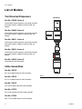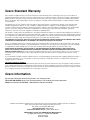
1
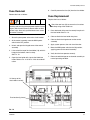
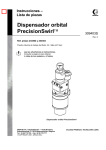
Instructions - Parts List
PrecisionSwirl™
Module
310554V
ENG
An orbital dispenser used to apply sealant and adhesive materials for a variety of
applications.
Part No. 241658, 234029, 289911 and 289912
3500 psi (24.1 MPa, 241 bar) Maximum Fluid Working Pressure
Important Safety Instructions
Read all warnings and instructions in this manual.
Save these instructions.
See page 2 for List of Models.
U.S. Patent No. 6,499,673
EU Patent No. 0852160
MOTOR FAULT
POWER
MAIN
RUN
RUN / ENABLE
CONTROL SELECT
MANUAL SPEED CONTROL
AUTOMATIC
MANUAL
8037B
PrecisionSwirl Control Assembly
918616
PrecisionSwirl
Orbital Dispenser
289261 and 289262
PrecisionSwirl
Orbital Dispenser
243402 and 243403
List of Models
List of Models
Tool Mounted Dispensers
Tool Mount
Part No. 241658, Series A
PrecisionSwirl Orbital Dispenser and Control Assembly
Kit includes 233123, 243403, 617829, 617870 and
918616.
Part No. 234029, Series A
PrecisionSwirl Orbital Dispenser and Control Assembly
Kit includes 233123, 243402, 617829, 617870 and
918616.
Part No. 289911, Series A
PrecisionSwirl Orbital Dispenser and Control Assembly
Kit includes 233123, 289261, 617829, 617870 and
918616.
Part No. 289912, Series A
PrecisionSwirl Orbital Dispenser and Control Assembly
Kit includes 233123, 289262, 617829, 617870 and
918616.
Part No. 918616, Series D
PrecisionSwirl Control Assembly
Cable Assemblies
Part No. 233125
6 ft (1.8 m) Motor Extension Cable Assembly
Part No. 233124
8130B
FIG. 1
9 ft (2.7 m) Motor Extension Cable Assembly
Part No. 233123
15 ft (4.6 m) Motor Extension Cable Assembly
Part No. 617870
55 ft (16.8 m) Motor Extension Cable Assembly
Part No. 617829
40 ft (12.2 m) Robot Interface Cable Assembly
2
310554V
List of Models
Contents
List of Models . . . . . . . . . . . . . . . . . . . . . . . . . . . . . . 2
Tool Mounted Dispensers . . . . . . . . . . . . . . . . . . 2
Cable Assemblies . . . . . . . . . . . . . . . . . . . . . . . . 2
Warnings . . . . . . . . . . . . . . . . . . . . . . . . . . . . . . . . . . 4
Unpacking and Repacking . . . . . . . . . . . . . . . . . . . 8
Unpacking the Product . . . . . . . . . . . . . . . . . . . . 8
Repair and Repacking the Product . . . . . . . . . . 8
PrecisionSwirl Overview . . . . . . . . . . . . . . . . . . . . 9
PrecisionSwirl Capabilities . . . . . . . . . . . . . . . . . 9
PrecisionSwirl in Basic Robotic System . . . . . . 10
Installing the Control Assembly . . . . . . . . . . . . . . 11
Preparing to Install the Control Assembly . . . . . 11
Mounting the Control Assembly . . . . . . . . . . . . 11
Mounting the Control Assembly (continued) . . . 12
Installation . . . . . . . . . . . . . . . . . . . . . . . . . . . . . . . 13
Grounding the Control Assembly . . . . . . . . . . . 13
Connecting the Control Assembly to a Power
Source . . . . . . . . . . . . . . . . . . . . . . . . . . . . 14
Connecting the Control Assembly to a Power
Source (continued) . . . . . . . . . . . . . . . . . . . 15
Checking Resistance Between the Control
Assembly and the True Earth Ground . . . . . 15
Installing the Dispense Valve . . . . . . . . . . . . . . . . 16
Mounting the Dispense Valve . . . . . . . . . . . . . . 16
Connecting Air Lines to Dispense Valve . . . . . . 16
Connecting Material Hose to Dispense Valve . 16
Installing Cable Assemblies . . . . . . . . . . . . . . . . . 17
Connecting the Motor Control Cable . . . . . . . . 17
Connecting the Motor Control Cable (continued) 18
Connecting the Automatic Control Cable . . . . . 19
Verifying Ground Continuity . . . . . . . . . . . . . . . . . 20
Verifying Ground Continuity . . . . . . . . . . . . . . . . 20
Adjusting the Orbital Dispenser . . . . . . . . . . . . 20
Inspecting the Orbital Dispenser . . . . . . . . . . . . 20
Grounding the System . . . . . . . . . . . . . . . . . . . . 20
PrecisionSwirl Module Operation . . . . . . . . . . . . 21
Reading the PrecisionSwirl Control Assembly
Controls and Indicators . . . . . . . . . . . . . . . . 21
Setting Operation Modes . . . . . . . . . . . . . . . . . . 22
Analyzing Causes for a Motor Fault Alarm . . . . 23
Adjusting Orbital Dispenser Motor Speed . . . . . 24
Troubleshooting . . . . . . . . . . . . . . . . . . . . . . . . . . . 25
310554V
Control Assembly Service . . . . . . . . . . . . . . . . . . . 26
Servicing the Control Assembly . . . . . . . . . . . . . 26
Lamp Button and Switch Removal . . . . . . . . . . . 26
Lamp Button and Switch Replacement . . . . . . . 26
Light Bulb Removal . . . . . . . . . . . . . . . . . . . . . . 26
Light Bulb Replacement . . . . . . . . . . . . . . . . . . 26
MAIN Power Switch Removal . . . . . . . . . . . . . . 27
MAIN Power Switch Replacement . . . . . . . . . . . 27
Potentiometer Removal . . . . . . . . . . . . . . . . . . . 28
Potentiometer Replacement . . . . . . . . . . . . . . . 28
Panel Assembly Service . . . . . . . . . . . . . . . . . . . . 29
Swirl Control Board Removal . . . . . . . . . . . . . . . 30
Swirl Control Board Replacement . . . . . . . . . . . 30
RFI Filter Removal . . . . . . . . . . . . . . . . . . . . . . . 31
RFI Filter Replacement . . . . . . . . . . . . . . . . . . . 31
Relay Removal . . . . . . . . . . . . . . . . . . . . . . . . . . 32
Relay Replacement . . . . . . . . . . . . . . . . . . . . . . 32
Fuse Removal . . . . . . . . . . . . . . . . . . . . . . . . . . 33
Fuse Replacement . . . . . . . . . . . . . . . . . . . . . . 33
Control Assembly Parts . . . . . . . . . . . . . . . . . . . . . 34
Accessory Parts . . . . . . . . . . . . . . . . . . . . . . . . . . . 40
Motor Control Cable Assemblies . . . . . . . . . . . . 40
Torsional Motor Control Cable Assemblies . . . . 41
Robot Interface Cable Assembly . . . . . . . . . . . . 42
Dispenser Valve Adapter Fittings . . . . . . . . . . . . 42
Wiring Diagrams . . . . . . . . . . . . . . . . . . . . . . . . . . . 43
Motor Controller Wiring, Lines 200-238 . . . . . . . 43
Motor Controller Wiring, Lines 250-288 . . . . . . . 44
Technical Data . . . . . . . . . . . . . . . . . . . . . . . . . . . . 45
Graco Standard Warranty . . . . . . . . . . . . . . . . . . . 46
Graco Information . . . . . . . . . . . . . . . . . . . . . . . . . 46
3
Warnings
Warnings
The following warnings are for the setup, use, grounding, maintenance, and repair of this equipment. The exclamation point symbol alerts you to a general warning and the hazard symbol refers to procedure-specific risk. Refer back
to these warnings. Additional, product-specific warnings may be found throughout the body of this manual where
applicable.
WARNING
EQUIPMENT MISUSE HAZARD
Equipment misuse can cause the equipment to rupture, malfunction, or start unexpectedly and result in
serious injury.
• This equipment is for professional use only.
• Read all instruction manuals, warnings, tags, and labels before operating the equipment.
• Use the equipment only for its intended purpose. If you are uncertain about usage, call your Graco
distributor.
• Do not alter or modify this equipment. Use only genuine Graco parts and accessories.
• Check the equipment daily. Repair or replace worn or damaged parts immediately.
• Do not exceed the maximum fluid working pressure of 3500 psi (241 bar, 24.1 MPa) to the dispenser
or manifold.
• Never exceed the recommended working pressure or the maximum air inlet pressure stated on your
pump or in the Technical Data section on page 63.
• Be sure that all spray/dispensing equipment and accessories are rated to withstand the maximum
working pressure of the pump. Do not exceed the maximum working pressure of any component or
accessory used in the system.
• Route hoses and cables away from traffic areas, sharp edges, moving parts, and hot surfaces.
• Do not expose Graco standard hoses to temperatures above 180° F (82° C) or below -40° F (-40° C).
• Do not use the hoses to pull the equipment.
• Use only fluids and solvents that are compatible with the equipment wetted parts. See the Technical
Data sections of all the equipment manuals. Read the fluid manufacturer’s warnings.
• Always wear protective eyewear, gloves, clothing, and respirator as recommended by the fluid and
solvent manufacturers.
• Comply with all applicable local, state, and national fire, electrical, and other safety regulations.
4
310554V
Warnings
WARNING
SKIN INJECTION HAZARD
Spray from the applicator, hose leaks, or ruptured components can inject fluid into your body and cause
extremely serious injury, including the need for amputation. Fluid splashed in the eyes or on the skin can
also cause serious injury.
• Fluid injected into the skin might look like just a cut, but it is a serious injury. Get immediate surgical
treatment.
• Do not point the applicator at anyone or at any part of the body.
• Do not put hand or fingers over the front of the applicator.
• Do not stop or deflect fluid leaks with your hand, body, glove, or rag.
• Follow the Pressure Relief Procedure from manual 309403 whenever you are instructed to: relieve
pressure; stop dispensing; clean, check, or service the equipment; or install or clean a nozzle.
• Tighten all the fluid connections before operating the equipment.
• Check the hoses, tubes, and couplings daily. Replace worn, damaged, or loose parts immediately.
Permanently coupled hoses cannot be repaired; replace the entire hose.
• Always wear eye protection and protective clothing when installing, operating, or servicing this dispensing equipment.
• Do not remove or modify any part of the applicator; this can cause a malfunction and result in serious bodily injury.
• Use extreme caution when cleaning or changing nozzles. If the nozzle clogs while applying material,
Always follow the Pressure Relief Procedure from manual 309403, then remove the nozzle to clean
it.
• Never wipe off build–up around the nozzle or inlet cap until pressure is fully relieved.
FIRE AND EXPLOSION HAZARD
Improper grounding, poor air ventilation, open flames, or sparks can cause a hazardous condition and
result in fire or explosion and serious injury.
• Ground the equipment and the object being dispensed. See Grounding on page 20.
• Ground the equipment and the object being sprayed, and all other electrically conductive objects in
the dispense area. Proper grounding dissipates static electricity generated in the equipment. See
Grounding on page 20.
• Do not use this equipment with flammable liquids.
• Keep the dispense area free of debris, including solvent, rags, and gasoline.
• If there is any static sparking or you feel an electric shock while using the equipment, stop dispensing immediately. Do not use the equipment until you have identified and corrected the problem.
• Be sure all electrical work is performed by a qualified electrician only.
• Have any checks, installation, or service to electrical equipment performed by a qualified electrician
only.
• Be sure all electrical equipment is installed and operated in compliance with applicable codes.
• Be sure power is disconnected when servicing and repairing equipment.
• Before operating the equipment, extinguish all open flames or pilot lights in the dispense area.
• Do not smoke in the dispensing area.
• Keep liquids away from the electrical components
• Disconnect electrical power at the main switch before servicing the equipment.
310554V
5
Warnings
WARNING
TOXIC FLUID OR FUMES HAZARD
Hazardous fluids or toxic fumes can cause serious injury or death if splashed in the eyes or on the skin,
swallowed, or inhaled.
• Provide fresh air ventilation to avoid the buildup of vapors from the fluid being dispensed.
• Know the specific hazards of the fluid you are using.
• Store hazardous fluid in an approved container. Dispose of hazardous fluid according to all local,
state, and national guidelines.
• Always wear protective eyewear, gloves, clothing, and respirator as recommended by the fluid and
solvent manufacturer.
• Avoid exposure to heated material fumes.
6
310554V
Warnings
310554V
7
Unpacking and Repacking
Unpacking and Repacking
Unpacking the Product
The PrecisionSwirl orbital dispenser and control assembly were carefully packaged for shipment by Graco.
When the package arrives, perform the following procedure to unpack the units:
1. Inspect the shipping box carefully for shipping damage. Contact the carrier promptly if damage is discovered.
2. Unseal the box and inspect the contents carefully.
There should not be any loose or damaged parts in
the bag.
2. Place the orbital dispenser and any loose or damaged parts in the same bag and box used in the
original shipment. Fill the box with filler material to
minimize the possibility of damage.
3. Seal the box tightly to protect its contents and prevent shipping damage.
4. Insure your shipment for the proper replacement
value of its contents.
5. Ship the orbital dispenser freight prepaid to your
authorized Graco distributor for service.
3. Compare the packing slip against all items included
in the box. Any shortages or other inspection problems should be reported immediately.
4. Store the box and packing materials in a safe place
for future use. Graco recommends that all packing
materials be saved in case the unit needs to be
shipped again.
Repair and Repacking the
Product
When the PrecisionSwirl orbital dispenser requires service, it is the purchaser’s responsibility to have the unit
repaired. As an option, the purchaser can have the unit
repaired by an authorized Graco distributor. For additional information, read the following subsections.
On–site Service
PrecisionSwirl components are customarily serviced by
the purchaser or an authorized Graco technician. When
service is required, follow the Service procedures in this
manual.
Service by an Authorized Graco Distributor
The PrecisionSwirl orbital dispenser can be serviced by
an authorized Graco distributor after completing a
Return Goods Authorization (RGA) form. The purchaser
must re–package and ship the orbital dispenser to the
Graco distributor. When repacking the orbital dispenser,
perform the following steps:
1. Retrieve the original box and packing materials for
shipment.
8
310554V
PrecisionSwirl Overview
PrecisionSwirl Overview
PrecisionSwirl Capabilities
The PrecisionSwirl orbital dispenser is regulated
through the control assembly. The orbital dispenser is
used to swirl sealant and adhesives in a variety of applications.
In a basic robotic system, the control assembly serves
as the interface between the robot controller and the
orbital dispenser via an interface cable. Refer to Robot
Interface Cable Assembly on page 52.
The orbital dispenser is operated either manually from
the control assembly or automatically from a robot controller where the orbital dispenser is programmed to
apply material continuously, or at interrupted intervals,
or both. The orbital dispenser can be stopped, started,
and regulated to suit the application, making high quality
swirl patterns that hold form after the material is dispensed.
The orbital dispenser applies a continuous swirled bead
of material directly on components in targeted areas,
such as the hem flanges on car doors, the interior
seams of the chassis, and on the fixed glass openings of
autos.
Bead profile is “pre–shaped” in a uniform pattern of
overlaid circular loops (see FIG. 2). Bead shape is
affected by nozzle size, material composition, flow rate,
stand off distance, and orbital dispenser motor speed.
The oscillating nozzle on the orbital dispenser can apply
an accurate swirled bead of material on vertical and horizontal planes.
8128B
FIG. 2
The orbital dispenser is small enough to apply sealant
and adhesives on any type of surface or material, and
can be directed on any programmable path, including: a
series of crevices, creases, or around a maze of straight
lines, sharp angles, contours, curves, corners, and
openings.
The material source for the orbital dispenser is commonly supplied via a dual ram pump fluid supply system,
which can be equipped with filters, temperature conditioning, and a fluid supply header.
310554V
9
PrecisionSwirl Overview
PrecisionSwirl in Basic Robotic
System
FIG. 3 shows the PrecisionSwirl components in a basic
robotic system. The following list identifies the PrecisionSwirl components:
No.
1
2
Description
Control assembly (PrecisionSwirl)
Orbital dispenser (PrecisionSwirl)
4
5
6
7
8
9
10
11
Automatic control cable (PrecisionSwirl). Also
called robot interface cable in this manual.
6, 9, or 15 ft (1.8, 2.7, or 4.6 m) flexible motor
cable for robot mounting (PrecisionSwirl)
55 ft (16.8 m) motor cable (PrecisionSwirl)
Dispense valve (not included)
Sealer robot
Robot controller
Fluid supply system
Fluid supply header
4
1
11
6
10
9
5
7
2
8
8024B
FIG. 3
10
310554V
Installing the Control Assembly
Installing the Control Assembly
To install the control assembly:
Mounting the Control Assembly
•
Prepare to install the control assembly
1. Select a location to mount the PrecisionSwirl control
assembly. Keep the following in mind:
•
Mount the control assembly
•
Ground the control assembly (electrically)
Allow sufficient space for mounting and using the equipment:
•
Connect control assembly to a power source
•
Mount the control assembly approximately 24-67 in.
(0.6-1.7 m) above the floor.
•
Check resistance between the control assembly and
a true earth ground.
•
Make sure all cables reach components without
strain.
•
Make sure there is sufficient space for repair, maintenance, and operation of the robot and applicator.
The National Electrical Code requires 3 ft (91.4 cm)
of open space in front of the control assembly.
•
Make sure there is sufficient clearance around the
control assembly for running fluid lines and cables to
other components.
•
Make sure there is easy and safe access to an
appropriate electrical power source.
ELECTROCUTION HAZARD
Installing and servicing this equipment requires access
to parts which could cause an electric shock or other
serious injury. Have only qualified electricians access
the control assembly.
Preparing to Install the Control
Assembly
Before installing the control assembly:
•
See component manuals for specific data on component requirements, such as a robot. Data presented here pertains to the PrecisionSwirl control
assembly only.
•
Have all applicable documentation available during
installation.
•
Use only the Graco PrecisionSwirl control assembly
with the PrecisionSwirl applicator.
2. Secure the PrecisionSwirl control assembly with
four 1/4 in. bolts through the 0.31 in. diameter holes
in the mounting flanges. See FIG. 4 for the mounting
hole spacing in the control assembly.
EQUIPMENT MISUSE HAZARD
The PrecisionSwirl control assembly weighs approximately 23.5 lb (10.7 kg). Exercise care when mounting
and handling the control assembly to prevent equipment damage or personal injury.
310554V
11
Installing the Control Assembly
Mounting the Control Assembly (continued)
7.05
(171.1 mm)
14.50
(368.3 mm)
16.00
(406.4 mm)
4x 0.13 in. (8 mm) diameter
mounting holes
14.50
(368.3 mm)
16.00
(152.4 mm)
NOTE: Hidden lines depict the
hole pattern for mounting the control
assembly.
NOTE: Conrol assembly must be
readily accessible and located 24-67
in. (0.6-1.7 m) above the floor.
7/8 in. diameter
hole for power
supply entry.
Robot control
cable connector
Motor cable
connector
FIG. 4
12
310554V
Installation
Installation
Grounding the Control Assembly
CAUTION
FIRE, EXPLOSION, AND ELECTRIC SHOCK
HAZARD
To reduce the risk of fire, explosion, or electric shock:
• The PrecisionSwirl control assembly must be electrically connected to a true earth ground; the
ground in the electrical system may not be sufficient.
• All wires used for grounding must be 8 AWG (8.36
mm2) minimum.
• A qualified electrician must complete all grounding
and wiring connections.
• Refer to your local code for the requirements for a
“true earth ground” in your area.
• Also read and follow the warnings on page 4.
If power and grounding connections are not done
properly, the equipment may be damaged and the
warranty will be voided.
CAUTION
To help avoid damage to equipment, make sure that
the robot and PrecisionSwirl equipment are grounded
to the same point.
Connect a ground wire from the GND terminal in the
PrecisionSwirl control assembly (shown in FIG. 5) to a
true earth ground.
*
*
*
*
*
*
#2
*
#2
#2
*
*
*
*
*
*
*
*
*
*
*
*
*
*
'.$
*
$.'
'.$
L2/N
L1
$.'
$.'
$.'
,,.0%
6!#
0(
(:
PE/GND
Power Terminals
NOTE: PE is the international designation for
the primary earth ground terminal. GND may
be used elsewhere on Graco equipment.
FIG. 5
310554V
13
Installation
Connecting the Control Assembly to a Power Source
Perform the following procedure to connect the control
assembly to a power source.
To connect the control assembly to the electrical source:
1. Shut off system power at the main circuit breaker.
2. Locate the opening on the bottom of the control
assembly, labeled POWER SUPPLY. See FIG. 6.
ELECTRIC SHOCK HAZARD
Do not connect the PrecisionSwirl control assembly to
a power source unless you are a trained electrician.
Failure to follow standard procedures or to observe the
necessary precautions could result in serious bodily
injury or equipment damage.
CAUTION
0/7%2
3500,9
!54/-!4)##/.42/,
#!",%
If power and grounding connections are not done
properly, the equipment may be damaged and the
warranty will be voided.
-/4/2
#!",%
8027A
7/8 in. Diameter power supply entry
Have a qualified electrician connect the PrecisionSwirl
control assembly to a grounded electrical source that
has the following required service ratings:
Description
Requirements
Vac
100-240
Hz
50/60
Phase
1
Full Load Amps
0.42 at 120 Vac
Circuit Breaker
5 Amp
Power to the control assembly must be supplied
from a source with a lockable–off disconnect
switch, or by use of a cord with a plug–and–socket
connection to the source of power.
14
FIG. 6
3. Using 16 AWG wire or larger, connect electrical
power to L1 (hot), L2 (neutral) power terminals in
the PrecisionSwirl control assembly. See FIG. 8.
4. Use a cord grip to seal the area where wires enter
the control assembly.
Any fitting that is used to connect a power cord (or
conduit for power wiring) to the control assembly
must provide a liquid–tight seal.
5. Apply system power at the main circuit breaker.
6. Move the POWER switch to the ON position, applying power to the control assembly.
310554V
Installation
Connecting the Control Assembly to a Power Source (continued)
*
*
*
*
*
*
#2
*
#2
#2
*
*
*
*
*
*
*
*
*
*
*
*
*
*
'.$
*
$.'
'.$
$.'
L2/N
L1
$.'
$.'
,,.0%
6!#
0(
(:
PE/GND
Power Terminals
FIG. 7
Checking Resistance Between
the Control Assembly and the
True Earth Ground
FIRE, EXPLOSION, AND ELECTRIC SHOCK
HAZARD
To reduce the risk of fire, explosion, or electric shock,
the resistance between the supply unit components
and true earth ground must be less than 0.25 ohms.
Have a qualified electrician check the resistance
between each system component and the true earth
ground. The resistance must be less than 0.25 ohms. If
the resistance is greater than 0.25 ohms, a different
ground site may be required. Do not operate the PrecisionSwirl module until the problem is corrected.
310554V
15
Installing the Dispense Valve
Installing the Dispense Valve
To install the dispense valve:
•
Mount the dispense valve
•
Connect the air lines
•
Connect material hose
Mounting the Dispense Valve
Attach the dispense valve to the mounting bracket on a
stationary support or robotic arm, using two socket head
screws (38) and flat washers (39).
The customer must provide a four–way pneumatic
valve, activated by a separate on/off dispense signal via the robot, to control material flow.
Connecting Air Lines to
Dispense Valve
Securely connect air lines to dispense valve air
ports (F). Make sure to connect the appropriate air lines
to the appropriate ports.
Connecting Material Hose to
Dispense Valve
Securely connect the material hose to dispense valve
inlet port (A).
Refer to Dispense Valve manuals 308876 and 309376.
16
310554V
Installing Cable Assemblies
Installing Cable Assemblies
CAUTION
Always make connections to the control assembly
with power turned off.
•
Keep cables from rubbing against other components
or machinery.
•
If a lot of robot wrist motion is required, leave sufficient cable length to allow for the motion, avoiding
any cable droops that may interfere with the machinery or substrate.
•
Route and secure the 7 in. motor cable to minimize
any movement. The 7 in. motor cable is not
intended to handle severe flexing motions.
•
Cable ties should only be used to loosely bundle
hoses together. Do not tighten cable ties to the point
where cable movement is restricted.
Connecting the Motor Control
Cable
Motor control cables are supplied in four lengths, 6 ft
(1.8 m), 9 ft (2.7 m), 15 ft (4.6 m), and 55 ft (16.8). The
55 ft cable may be used by itself. The 6 ft, 9 ft, and 15 ft
cable must be used with the 55 ft cable.
To connect the motor cable between the control assembly and the orbital dispenser, do the following:
1. Locate the receptacle on the bottom of the control
assembly that is labeled MOTOR CABLE. See FIG.
8.
0/7%2
3500,9
!54/-!4)##/.42/,
#!",%
-/4/2
#!",%
8027A
Motor cable receptacle
FIG. 8
2. Connect the orbital dispenser cable (55 ft) to the
MOTOR CABLE receptacle. See FIG. 9.
3. Check the connections to ensure the cable is connected correctly.
4. Route the motor control cable and conform to the
following cable routing requirements:
•
Avoid a bend radius of less than 5 in. (12.7 cm).
•
Avoid pinch points.
•
Avoid cable pulling or stretching.
310554V
17
Installing Cable Assemblies
Connecting the Motor Control Cable (continued)
0/7%2
-/4/2&!5,4
25.
Motor Control Cable (15 ft)
-!).
#/.42/,3%,%#4
!54/-!4)#
25.%.!",%
-!.5!,30%%$#/.42/,
-!.5!,
Motor Control
Cable (55 ft)
ti0657B
FIG. 9
18
310554V
Installing Cable Assemblies
Connecting the Automatic
Control Cable
5. Check the connections to ensure the cable is connected correctly.
Automatic control cable receptacle
CAUTION
Always make connections to the control assembly
with power turned off.
The PrecisionSwirl control assembly is provided with a
9–pin receptacle for the robot interface cable.
Any wiring from an external source, such as a robot
controller, must follow the robot manufacturer’s
instructions and must comply with the appropriate
codes and standards.
0/7%2
3500,9
!54/-!4)##/.42/,
#!",%
-/4/2
#!",%
ti0827A
FIG. 10
To connect the automatic control cable (P/N 617829)
between the control assembly and the robot, perform
the following steps:
1. Locate the receptacle on the bottom of the control
assembly that is labeled AUTOMATIC CONTROL
CABLE. See FIG. 10.
2. Connect the cable assembly to the AUTOMATIC
CONTROL CABLE receptacle in FIG. 10.
3. Secure the cable by tightening the two mounting
screws.
Signal
Description
Enable
The 24V enable signal starts the orbital dispenser motor.
Swirl
This 0-10 VDC analog signal is used to
Speed
adjust the motor speed. (0-10 VDC =
Command 6600-24,000 RPM)
Motor
Fault
Alarm
A fault will be generated if any of the front
panel controls are in the wrong position for
automatic operation
4. Connect the opposite end of the cable assembly to
the applicable terminals or receptacle on the robot
controller.
For information about specific control assembly circuitry
and connections, read the chart below and see the Wiring Diagrams on pages 56 and 57, and FIG. 11.
The alarm relay activates when the motor
speed drops below 1500 RPM or does not
start. The relay contacts are normally
closed.
Swirl
Speed
Readout
This analog signal can be used to monitor
motor speed.
(0-10 VDC = 0-24,000 RPM)
-/4/2&!5,4
0/7%2
-!).
25.
25.%.!",%
#/.42/,3%,%#4
!54/-!4)#
Robot controller
-!.5!,
-!.5!,30%%$#/.42/,
8029A
FIG. 11
310554V
19
Verifying Ground Continuity
Verifying Ground Continuity
Verifying Ground Continuity
Verify ground continuity between:
•
•
True earth ground and the control assembly ground
terminal
The orbital dispenser and the robot
3. Fluid and air hoses: use only electrically conductive
material and air hoses.
4. Dispense gun: obtain grounding through the connection of the hose, or cable.
5. Air compressor: follow the manufacturer’s recommendations.
6. Object being sprayed: according to local code.
Adjusting the Orbital Dispenser
7. Fluid supply container: according to local code.
The PrecisionSwirl orbital dispenser is calibrated at the
factory. No adjustment is required during initial setup.
Before applying power, read the reference information
provided about controls and indicators to become familiar with the equipment.
Inspecting the Orbital Dispenser
Inspect the orbital dispenser cables, material, and air
hoses daily for leakage and other visible damage.
Grounding the System
FIRE AND EXPLOSION HAZARD
To reduce the risk of a fire, explosion, and serious
injury, proper electrical grounding of every part of your
system is essential. Read the warning section, FIRE
AND EXPLOSION HAZARD, on page 5 and follow the
grounding instructions below.
The following grounding instructions are minimum
requirements for a basic dispensing system. Your system may include other equipment or objects which must
be grounded. Check your local electrical code for
detailed grounding instructions for your area and type of
equipment. Your system must be connected to a true
earth ground.
1. Pump: connect a ground wire and clamp to a true
earth ground as shown in separate pump manual.
2. Orbital Dispenser: obtain grounding through the
motor cable assembly.
20
310554V
PrecisionSwirl Module Operation
PrecisionSwirl Module Operation
Reading the PrecisionSwirl Control Assembly Controls and
Indicators
Table 1 describes the controls on the PrecisionSwirl control assembly. See FIG. 12 for an illustration of the controls
and indicators.
Table 1. Control Assembly Controls
Button/Switch
What it does
MAIN ON/OFF Switch
Controls power to the system.
•
•
Control Select Switch
AUTOMATIC / MANUAL
In the MAIN ON (I) position, system power is turned on.
n the OFF (0) position, system power is turned off.
Switches the orbital dispenser to automatic or manual control.
•
•
In the AUTOMATIC position, the orbital dispenser is controlled from a
remote source, such as a robot, via an interface cable.
In the MANUAL position, the orbital dispenser is controlled directly from
the control assembly front panel.
RUN / ENABLE Button
Pushing the RUN/ENABLE (black) button starts the orbital dispenser motor
in manual mode or enables the motor to be started in automatic mode.
STOP Button
Pushing the STOP (red) button removes power from the orbital dispenser.
MANUAL SPEED CONTROL Knob
(potentiometer)
Regulates the motor speed of the orbital dispenser in the manual control
mode.
•
•
Rotating the control knob clockwise increases motor speed.
Rotating the control knob counter–clockwise decreases motor speed.
Table 2 describes the indicators on the PrecisionSwirl control assembly. See FIG. 12 for an illustration of the controls
and indicators.
Table 2. Control Assembly Indicators
Button/Switch
POWER (white
RUN (green)
MOTOR FAULT (red)
310554V
Indicator
Light is
Meaning
ON
Power is on.
OFF
Power is off.
ON
PrecisionSwirl orbital dispenser is ready for operation, or is
operating in manual control mode.
OFF
PrecisionSwirl orbital dispenser is not ready for operation, or
is not operating in manual control mode.
ON
Motor is not rotating. Or, the motor is rotating below the minimum speed.
OFF
Motor is functioning properly.
21
PrecisionSwirl Module Operation
-/4/2&!5,4
0/7%2
-!).
25.%.!",%
#/.42/,3%,%#4
!54/-!4)#
25.
-!.5!,30%%$#/.42/,
-!.5!,
8030A
FIG. 12
Setting Operation Modes
The PrecisionSwirl module has two operating states:
•
•
Automatic mode — enables the PrecisionSwirl
orbital dispenser to be controlled by a remote signal
source, such as a robot control. Motor speed can be
controlled by a 0-10 VDC analog signal.
Manual mode — enables the PrecisionSwirl orbital
dispenser to swirl when you press the
RUN/ENABLE button on the control assembly.
Swirling continues until the STOP button is pressed.
Material flow rate and “ON/OFF” flow are not controlled by the PrecisionSwirl orbital dispenser.
These must be controlled by the other interfaces.
Contact your Graco Distributor for assistance.
The PrecisionSwirl orbital dispenser is in an idle state
until you press the RUN/ENABLE button on the control
assembly. The only time the PrecisionSwirl orbital dispenser can swirl material is when the RUN/ENABLE
button is pressed in either Automatic or Manual mode.
When the STOP button is pressed, the PrecisionSwirl
orbital dispenser becomes idle and will not swirl material.
The procedures in this section configure the module for
manual or automatic operation.
22
310554V
PrecisionSwirl Module Operation
Using Automatic Mode
Entering Automatic Mode
The system is now ready to dispense. Make sure
dispensing will not endanger people or equipment
before proceeding.
To put the PrecisionSwirl module into Automatic mode:
You are about to place the system under robotic
control. Make sure dispensing will not endanger
people or equipment before proceeding.
3. Press the RUN/ENABLE (black) button. Make sure
the green RUN indicator, shown in
FIG. 12, is lit at the control assembly.
The PrecisionSwirl orbital dispenser motor starts immediately.
1. Make sure the POWER indicator, shown in FIG. 12,
is lit at the control assembly. If it is not, turn the
MAIN power switch to the ON position, turning on
power to the PrecisionSwirl control assembly circuitry.
2. Set the CONTROL SELECT switch to AUTOMATIC.
3. Press the RUN/ENABLE (black) button. Make sure
the green RUN indicator, shown in FIG. 12, is lit at
the control assembly.
The PrecisionSwirl orbital dispenser is now enabled.
When it receives a 24 Volt RUN/ENABLE command
from the robot, the PrecisionSwirl orbital dispenser
motor starts and reaches full speed in about one second. The orbital dispenser motor stops when the 24 Volt
RUN/ENABLE command is removed.
4. Leave the control assembly in this state during normal operation.
Leaving Automatic Mode
Stop Manual Swirling
To stop manual swirling and idle the module:
1. Press the STOP (red) button.
The PrecisionSwirl orbital dispenser is now disabled and
will stop swirling material.
2. Make sure the green RUN indicator, shown in
FIG. 12, is off at the control assembly.
Analyzing Causes for a Motor
Fault Alarm
Circuitry on the relay board monitors the motor speed to
verify that the motor is functioning properly.
When the motor functions improperly, the circuitry on
the relay board activates the motor fault alarm. The
alarm turns on when:
To leave Automatic dispense mode and idle the module:
•
the motor speed has not risen within the +/-50% tolerance range within five seconds after startup.
•
the motor speed is outside the tolerance range for at
least five seconds while operating.
1. Press the STOP (red) button.
2. Set the CONTROL SELECT switch to MANUAL.
3. Make sure the green RUN indicator, shown in
FIG. 12, is off at the control assembly.
Using Manual Mode
1. Make sure the POWER indicator, in FIG. 12, is lit at
the control assembly. If it is not, turn the MAIN
power switch to the ON position, turning on power to
the PrecisionSwirl control assembly circuitry.
2. Set the CONTROL SELECT switch to MANUAL.
310554V
When a fault occurs, the motor fault light on the control
panel illuminates, and the alarm relay activates sending
the fault signal out via the automatic control cable. The
alarm remains turned on until the fault condition is corrected or the run command is removed.
A fault will also be generated if any of the front panel
controls are not in the correct position for automatic
operation (power switch, enable switch, manual/auto
switch).
23
PrecisionSwirl Module Operation
Adjusting Orbital Dispenser Motor Speed
Adjust the orbital dispenser motor speed in the manual or automatic control mode as described in the following paragraphs.
Manual Mode:
Automatic Mode:
Adjust motor speed by rotating the MANUAL SPEED
CONTROL knob on the control box. See FIG. 12.
Use the motor speed chart (FIG. 13) to find the voltage
setting required to achieve the desired motor speed.
When the control signal voltage is increased, the motor
speed increases. When the control signal voltage is
decreased, the motor speed decreases.
Rotate the knob clockwise to increase speed and counterclockwise to decrease speed. Use the motor speed
chart (FIG. 13) to find the manual control setting required
to achieve the desired motor speed.
Exceeding the maximum analog speed control voltage may result in damage to the motor controller.
0-10 VOLT
PrecisionSwirl Motor Speed Command
24
22
20
SPEED IN RPM x 1000
18
16
14
12
10
8
6
4
2
0
0
1
2
3
4
5
6
7
8
9
Analog speed signal from robot (Volts dc)
OR
Manual control setting
FIG. 13
24
310554V
Troubleshooting
Troubleshooting
Some solutions require disassembling the dispense valve or orbital dispenser. Always relieve system pressure before
performing these procedures.
Table 3 provides troubleshooting information. For other troubleshooting situations, call your Graco distributor.
To reduce the risk of serious injury whenever you are
instructed to relieve pressure, always follow the Pressure Relief Procedure (see manual 309043).
To reduce the risk of serious injury whenever you are
instructed to remove, change, check, clean, or handle the nozzle in any manner, always disconnect the
motor control cable from the control assembly (see
FIG. 8 on page 17), or place the control assembly in
the MANUAL mode of operation using the CONTROL SELECT switch. (See FIG. 12 on page 22.)
Table 3. Troubleshooting
Problem
No material being dispensed
Material dispensing but not swirling
(Motor fault light is on)
Cause
Solution
Clogged nozzle
Change nozzle.
No material or pressure
Check fluid delivery system.
Broken or clogged dispense tube
Rebuild the orbital dispenser.
Fault in dispense valve
Refer to Dispense Valve manuals
308876 or 309376.
Motor not operating
Check wiring connections and cable.
Tube bearing defective; replace tube
bearing.
Motor defective; replace motor.
Check for fluid leak.
Control assembly failure
Check analog voltage control setting
and enable signal.
Check RPM setting.
Check power and fuses.
Check wiring.
Material dispensing but not swirling
Orbiter bearing failure
Replace bearing.
Material accumulating on nozzle
Clean nozzle.
(Motor fault light is off)
Motor is rotating but poor swirl pattern or change in bead size
310554V
Flow rate has changed
Check flow rate.
Motor speed has changed
Check analog speed signal.
Material viscosity has changed
Check material parameters.
Partially clogged nozzle
Clean nozzle.
25
Control Assembly Service
Control Assembly Service
Servicing the Control Assembly
2. Refer to FIG. 21 and FIG. 22 for lead wire identification.
This part of the manual provides information about the
following control assembly components:
3. Apply system power at the main circuit breaker.
•
•
•
•
Indicator Lamp Button and Select Switch (page 26)
Light Bulb (page 26)
MAIN Power Switch (page 27)
Potentiometer (page 28)
Refer to the Parts information on pages 34, 36, and
38 while servicing the control assembly.
Lamp Button and Switch
Removal
ELECTROCUTION HAZARD
Installing and servicing this equipment requires access
to parts which could cause an electric shock or other
serious injury. Have only qualified electricians access
the control assembly.
4. Move the MAIN power switch to the ON position,
applying power to the control assembly.
5. Verify that the replaced fixture operates correctly.
6. Return the orbital dispenser and control assembly to
normal operating condition.
Light Bulb Removal
Remove the light bulb as follows:
ELECTROCUTION HAZARD
Installing and servicing this equipment requires access
to parts which could cause an electric shock or other
serious injury. Have only qualified electricians access
the control assembly.
1. Shut off system power at the main circuit breaker.
1. Shut off system power at the main circuit breaker.
2. At the control assembly, move the MAIN power
switch to the OFF position.
3. Unlock and open the hinged cover of the control
assembly enclosure.
4. Disconnect the lead wires from the fixture terminals.
Refer to FIG. 21 and FIG. 22 for lead wire identification. If necessary, label the wires to facilitate reassembly after the fixture is replaced.
2. At the control assembly, move the MAIN power
switch to the OFF position.
3. Unscrew and remove the indicator light lens.
4. Gently press and rotate the bulb counter-clockwise,
1/4 in. of a turn, unlocking the bulb from its socket.
Remove the bulb from the socket.
Light Bulb Replacement
Replace the light bulb as follows:
5. Loosen two screws which clamp the fixture to the
cover. Rotate the fixture counter–clockwise relative
to the lens cover or switch operator. Separate the
two parts of the fixture and remove them from the
cover.
1. Insert the light bulb in the socket.
Lamp Button and Switch
Replacement
4. Apply system power at the main circuit breaker.
1. Reverse the disassembly procedures 3-5 in the previous section.
26
2. Gently press and rotate the bulb clockwise, 1/4 in. of
a turn to lock the bulb in its socket.
3. Replace the lens.
5. Move the MAIN power switch to the ON position,
applying power to the control assembly.
6. Verify that the light bulb operates correctly.
310554V
Control Assembly Service
7. Return the control assembly to normal operating
condition.
6. Remove two flat head screws from the yellow
mounting plate, which fastens the switch to the
hinged cover. Remove the switch.
MAIN Power Switch Removal
Remove the MAIN power switch as follows:
MAIN Power Switch
Replacement
Replace the MAIN power switch as follows:
ELECTROCUTION HAZARD
Installing and servicing this equipment requires access
to parts which could cause an electric shock or other
serious injury. Have only qualified electricians access
the control assembly
1. Shut off system power at the main circuit breaker.
2. At the control assembly, move the MAIN power
switch to the OFF position. See FIG. 14.
3. Unlock and open the hinged cover of the control
assembly.
4. Disconnect the lead wires from the four terminals on
the MAIN power switch. Refer to FIG. 21 and FIG. 22
for lead wire identification. If necessary, label the
wires to facilitate reassembly after the switch is
replaced.
5. Remove one flat head screw that secures the red
rotor to the switch assembly. Lift the rotor from the
switch.
1. Assemble the switch assembly to the yellow mounting plate with two flat head screws.
2. Assemble the red rotor, which is keyed, onto the yellow mounting plate with one flat head screw. See
Fig. 15.
3. Turn the rotor to point down to ensure that the
switch is in the OFF position.
4. Reconnect the lead wires to the terminals on the
switch. Refer to Fig. 18 to make sure that the connections are correct.
5. Close and lock the hinged cover on the control
assembly.
6. Apply system power at the main circuit breaker.
7. Move the MAIN power switch to the ON position
applying power to the control assembly.
8. Verify that the switch operates correctly.
MAIN power switch (back panel)
Yellow
mounting
plate
-/4/2&!5,4
0/7%2
25.
2331
2292
2131
2292
-!).
25.%.!",%
Red rotor
2132
2132
2132
2132
2132
2132
2131
#/.42/,3%,%#4
MAIN
power
switch
!54/-!4)#
2131
2121
-!.5!,30%%$#/.42/,
2291
2122
2291
-!.5!,
2292
2081
2291
2082
2131
2131
2131
2261
2DNG
8039B
FIG. 14
310554V
27
Control Assembly Service
Potentiometer Removal
Potentiometer Replacement
Remove the potentiometer as follows:
Replace the potentiometer as follows:
ELECTROCUTION HAZARD
Installing and servicing this equipment requires access
to parts which could cause an electric shock or other
serious injury. Have only qualified electricians access
the control assembly.
1. Shut off system power at the main circuit breaker.
2. At the control assembly, move the MAIN power
switch to the OFF position.
3. Unlock and open the hinged cover of the control
assembly.
4. Pull lead wires to remove from potentiometer.
5. Loosen setscrew (not shown) in the vernier dial
knob and remove dial assembly from the potentiometer shaft.
6. Remove the hex nut and lockwasher from potentiometer shaft, and remove the potentiometer.
Vernier dial
1. Insert the potentiometer through its hole from the
back of the enclosure cover and rotate it so that terminals 1 and 3 are oriented at approximately 4:30
when viewed from the back. Refer to FIG. 16.
Assemble the lockwasher and nut onto the shaft and
secure the potentiometer to the cover.
2. At the front of the cover, turn the potentiometer shaft
counter–clockwise to its stop.
3. Pre–set the vernier dial to 0.00 and place it over the
potentiometer shaft, with its key tab inserted into the
blind hole in the cover front surface. Tighten the dial
setscrew (not shown) against the shaft.
4. Verify that the potentiometer is turned fully counterclockwise when the vernier dial indicates 0.00.
Loosen the setscrew and reposition the shaft and
dial if necessary, then retighten the setscrew.
5. Connect wire leads to potentiometer.
6. Close and lock the cover on the control assembly.
7. Apply system power at the main circuit breaker.
8. Move the MAIN power switch to the ON position,
applying power to the control assembly.
9. In the MANUAL control mode, verify that the potentiometer operates correctly.
Cover
Potentiometer
10. Return the orbital dispenser and control assembly to
normal operating condition.
3 1 2
Terminals 1 and 3
Nut
Locating
Tab
2172
2132
2181
8040A
FIG. 15
Terminal 2
2181
2132
2172
8034B
FIG. 16
28
310554V
310554V
,.
,
6
6
'.$
0/44%2-
6!#0(
(:
, ,. 0%
'.$
'.$
#2
#2
3
3
3
6
6
!
"
#
25..%54#/-
25.6
$##/-
-42!#430%%$6$#
#6$#
•
•
•
•
!,!2-2%,!9).
*
*
*
*
*
*
*
*
Relay Board
*
*
This part of the manual provides information about the
following panel assembly components:
!,!2-2%,!9/54
'.$
*
*
*
*
*
*
*
*
*
*
*
*
0/44%2-
.#
.#
0/44%2-
34/00"25.,4
3%,%#4!54/
'.$
-/4/2&!5,4
25.0"34/00"
Panel Assembly Service
Panel Assembly Service
Swirl Control Board (page 30)
RFI Filter (page 31)
Relay (page 32)
Fuse (page 33)
Motor Control
#2
RFI Filter
2/"/4
-/4/2
Spacers and lockwashers (6 total)
FIG. 17
29
Panel Assembly Service
Swirl Control Board Removal
Remove the relay board as follows:
Swirl Control Board
Replacement
Replace the relay board as follows:
1. Snap the swirl control board onto the din rail.
ELECTROCUTION HAZARD
Installing and servicing this equipment requires access
to parts which could cause an electric shock or other
serious injury. Have only qualified electricians access
the control assembly.
2. Plug the connectors into the swirl control board.
Refer to FIG. 17 for lead wire identification.
3. Close and lock the hinged cover on the control
assembly.
4. Apply system power at the main circuit breaker.
1. Shut off system power at the main circuit breaker.
2. At the control assembly, move the MAIN power
switch to the OFF position.
3. Unlock and open the hinged cover of the control
assembly.
5. Move the MAIN power switch to the ON position,
applying power to the control assembly.
6. Verify that the relay board operates correctly.
7. Return the control assembly to normal operating
condition.
4. Unplug the connectors from the swirl control board.
5. Pry the plastic cups off the board with a screwdriver
to release the board from the din rail.
30
310554V
Panel Assembly Service
RFI Filter Removal
RFI Filter Replacement
Remove the RFI Filter as follows:
Replace the RFI filter as follows:
1. Install the RFI filter using the two screws and lockwashers to secure the component on the panel
assembly. See FIG. 17.
ELECTROCUTION HAZARD
Installing and servicing this equipment requires access
to parts which could cause an electric shock or other
serious injury. Have only qualified electricians access
the control assembly.
2. Connect the wires to the correct terminal block on
the control board. Refer to FIG. 17 for lead wire identification.
3. Close and lock the hinged cover on the control
assembly.
1. Shut off system power at the main circuit breaker.
4. Apply system power at the main circuit breaker.
2. At the control assembly, move the MAIN power
switch to the OFF position.
5. Move the MAIN power switch to the ON position,
applying power to the control assembly.
3. Unlock and open the hinged cover of the control
assembly.
6. Verify that the RFI filter operates correctly.
4. Disconnect the wires from the terminal blocks on the
control board. If necessary, label the wires to facilitate reassembly after the control board is replaced.
7. Return the control assembly to normal operating
condition.
5. Remove the two screws and lockwashers from the
RFI filter on the panel assembly. See FIG. 17.
6. Remove the RFI filter.
310554V
31
Panel Assembly Service
Relay Removal
Relay Replacement
Remove the relay as follows:
Replace the relay as follows:
Relays are always P/N 15A797, 24 VDC. If the
robot run command signal for automatic control
mode is 24 VDC, then relay is also P/N 15A797.
ELECTROCUTION HAZARD
Installing and servicing this equipment requires access
to parts which could cause an electric shock or other
serious injury. Have only qualified electricians access
the control assembly.
1. Match pattern on bottom side of relay to base. Plug
relay into base. FIG. 18.
2. Close and lock the hinged cover on the control
assembly.
1. Shut off system power at the main circuit breaker.
3. Apply system power at the main circuit breaker.
2. At the control assembly, move the MAIN power
switch to the OFF position.
4. Move the MAIN power switch to the ON position,
applying power to the control assembly.
5. Verify that the relay operates correctly.
4. With force, carefully pull the top of the relay to
unplug the relay from the base. See FIG. 18.
6. Return the control assembly to normal operating
condition.
3
3
3
6
6
!
"
#
'.$
25.6
25..%54#/-
$##/-
#6$#
-42!#430%%$6$#
'.$
!,!2-2%,!9).
*
#2
*
*
, ,. 0%
6!#0(
(:
#2
Wire retainer
!,!2-2%,!9/54
'.$
*
*
*
*
,.
*
,
6
6
'.$
0/44%2-
0/44%2-
*
*
#2
0/44%2-
34/00"25.,4
3%,%#4!54/
'.$
-/4/2&!5,4
25.0"34/00"
*
*
*
*
*
*
*
*
*
*
*
*
.#
.#
3. Unlock and open the hinged cover of the control
assembly.
-/4/2
2/"/4
FIG. 18
32
310554V
Panel Assembly Service
Fuse Removal
6. Carefully remove the fuse (24) from the fuse holder.
Remove the fuse as follows:
Fuse Replacement
Replace the fuse as follows:
Check the new fuse (24) to ensure that it matches
the Amp rating of the failed fuse.
ELECTROCUTION HAZARD
Installing and servicing this equipment requires access
to parts which could cause an electric shock or other
serious injury. Have only qualified electricians access
the control assembly.
1. Press both ends of the new fuse evenly into place in
the fuse holder. See FIG. 19.
2. Close and lock the fuse holder into place.
1. Shut off system power at the main circuit breaker.
3. Close and lock the hinged cover on the control
assembly.
2. At the control assembly, move the MAIN power
switch to the OFF position.
4. Apply system power at the main circuit breaker.
3. Unlock and open the hinged cover of the control
assembly.
5. Move the MAIN power switch to the ON position,
applying power to the control assembly.
4. Lift to unlock the top of the fuse holder (10), which is
hinged at the bottom, from its clamp.
See FIG. 19.
6. Verify that the fuse operates correctly.
7. Return the orbital dispenser and control assembly to
normal operating condition.
*
#2
*
*
*
*
#2
*
'.$
*
*
*
*
#2
3%,%#4!54/
*
*
*
*
*
*
*
*
*
*
*
*
25.0"34/00"
Lift the top of the
fuse holder to unlock
.#
.#
5. Open the fuse holder fully. Locate the failed fuse
inside. Refer to FIG. 21 and FIG. 22 for fuse identification.
3
3
3
6
6
!
"
#
'.$
25.6
25..%54#/-
$##/-
-42!#430%%$6$#
'.$
#6$#
6!#0(
(:
!,!2-2%,!9/54
, ,. 0%
!,!2-2%,!9).
,
6
6
,.
'.$
0/44%2-
0/44%2-
0/44%2-
34/00"25.,4
-/4/2&!5,4
'.$
Fuse location (2 places)
-/4/2
2/"/4
FIG. 19
310554V
33
Control Assembly Parts
Control Assembly Parts
Part No. 918616, PrecisionSwirl Control
Assembly
Ref.
No.
1
2
3
4
5
Part No.
241487
194896
241580
241600
617771
6
8
9
13
14
15
16
17
18
19
20
241599
C19949
115237
617777
617778
617779
617780
617781
617782
617783
617775
21
22†
23†
24†
31
32▲†
34†
35
36
42
43
44†
45
47†
51
52
53
617776
113285
100718
617774
194897
617472
C19738
C78216
C78321
100731
100133
100307
195899
114887
115217
194984
115434
Description
Qty.
CABINET, PrecisionSwirl
1
LABEL, front panel,
1
PANEL, ASSY, control
1
CONNECTOR, motor
1
GASKET, flange, electrical connec- 1
tor, #14
CONNECTOR, robot
1
SCREW, SHC, #4-40 x 0.25
4
SWITCH, power, rotary
1
LIGHT base, direct supply
2
LENS, light, white, 7/8
1
LENS, light, green, 7/8
1
LAMP, incandescent, 24V
2
SWITCH BASE, 1-NO, 1-NC
2
ACTUATOR, switch, 2–PB, rect
1
ACTUATOR, switch, 2 position
1
POTENTIOMETER, 10 turn, 10K 1
ohm, 0.5W
DIAL, vernier, 15 turn
1
TERMINAL, ring, #10
2
WASHER
2
NUT, hex, #10-32, brass
4
LABEL, cable connector
1
LABEL, danger, electric shock
1
SCREW, drive, round head
4
CLAMP, ty–rap
10
TIE, cable, 3.62 long
18
WASHER
4
WASHER, lock
4
NUT, full, hex
4
DUCT, wire, 10 in.
1
KEY, latch, door
1
SCREW, female, kit
1
COVER, wire, duct, 10 in.
1
LENS, light, red, 7/8
1
† These parts are not shown on the parts drawing.
▲ Replacement Danger and Warning labels, tags, and
cards are available at no cost.
34
310554V
Control Assembly Parts
Part No. 918616, PrecisionSwirl Control Assembly
1
2
MOTOR FAULT
POWER
RUN
MAIN
RUN / ENABLE
20, 21
CONTROL SELECT
MANUAL SPEED CONTROL
AUTOMATIC
MANUAL
8037B
46
6, 51
8, 4, 5
31
0/7%2
3500,9
!54/-!4)##/.42/,
#!",%
-/4/2
#!",%
8027A
FIG. 20
310554V
35
Control Assembly Parts
Part No. 918616, PrecisionSwirl Control Assembly
13, 15, 16
13, 14, 16
13, 53, 16
9
17, 18
'.$
36
45, 48
52
17, 19
35
FIG. 21
36
310554V
310554V
6!#
0(
(:
'.$
*
#2
*
*
*
#2
*
*
*
*
*
*
*
*
*
'.$
*
*
*
*
'.$
'.$
Control Assembly Parts
Part No. 918616, PrecisionSwirl Control Assembly
42, 43, 16
*
*
*
*
#2
*
3
, ,. 0%
FIG. 22
37
Control Assembly Parts
Part No. 241580, PrecisionSwirl Panel Assembly
Ref.
No.
1
2
3
5
7
8
9
10
11
12
13
Part No.
194693
115215
194895
244355
102410
100272
112443
514556
115234
112446
112442
Description
PLATE
POWER SUPPLY
RAIL, mount
BOARD, swirl control
SCREW, cap, socket head
WASHER, lock, internal tooth
BLOCK, terminal, ground
HOLDER, fuse
COVER, terminal
BLOCK, clamp, end
BLOCK, terminal
Ref.
No.
14
15
16
21
22
23†
24†
26
Qty.
1
1
2
1
2
2
8
2
1
7
23
Part No.
103833
115212
194894
194976
100718
115130
115216
194985
Description
SCREW, machine, bdgn
FILTER, RFI
DUCT, wire
LABEL, wiring
WASHER
JUMPER PIN
FUSE, 2 AMP High Interrupting
COVER, wire, duct, 14 in.
Qty.
12
1
1
1
12
1
2
1
† These parts are not shown on the parts drawing.
7
#2
#2
*
*
*
*
*
*
*
*
*
*
#2
1
*
*
*
*
*
*
*
*
*
*
*
*
.#
.#
5
6, 8
26
16
14, 22
15
'.$
7, 8
13
3
3
3
6
6
!
"
#
'.$
25.6
$##/-
25..%54#/-
-42!#430%%$6$#
'.$
#6$#
6!#0(
(:
!,!2-2%,!9).
, ,. 0%
!,!2-2%,!9/54
,.
,
6
6
'.$
0/44%2-
0/44%2-
0/44%2-
3%,%#4!54/
34/00"25.,4
'.$
-/4/2&!5,4
25.0"34/00"
12
3
-/4/2
2/"/4
21
9
10, 26
11
2
FIG. 23
38
310554V
Control Assembly Parts
310554V
39
Accessory Parts
Accessory Parts
Motor Control Cable Assemblies
Table 5. Motor Control Cables
The motor control cables that are provided with the
module are OLFLEX® brand cables. The 55 ft (16.8)
motor cable (617870) can be used alone.
Part Number
Length
Description
617870
55 ft (16.8 m)
Motor cable assembly
SOCKET
PIN
P/N 617870
A
B
C
D
E
H
J
K
L
M
WHITE
BROWN
GREEN
YELLOW
GREY
A
B
C
D
E
RED 1
RED 2
RED 3
GREEN/YELLOW
H
J
K
L
M
CONNECTION DIAGRAM
FUNCTION
V+
SENSOR 1
SENSOR 2
SENSOR 3
VSHIELD TIED TO CONNECTOR SHELL
SHIELD TIED TO CONNECTOR SHELL
MOTOR PH. A
MOTOR PH. B
MOTOR PH. C
GROUND
8031A
FIG. 24
40
310554V
Accessory Parts
Torsional Motor Control Cable
Assemblies
For robot applications that have a lot of torsional motion
to the cable in addition to bending. These cables are
made from Olflex 900 series robot cable that are
designed to handle more torsional loads. The cables
must be used in conjunction with the 55 ft motor cable.
Table 6. Motor Control Cables
Part Number
Length
Description
233125
6 ft (1.8 m)
Motor cable assembly
233124
9 ft (2.7 m)
Motor cable assembly
233123
15 ft (4.6 m)
Motor cable assembly
P/N 233123, 233124, 233125
SOCKET
A
B
C
D
E
H
J
K
L
M
PIN
WHITE
BROWN
GREEN
YELLOW
GREY
A
B
C
D
E
FUNCTION
V+
SENSOR 1
SENSOR 2
SENSOR 3
V-
1
2
3
GREEN/YELLOW
H
J
K
L
M
MOTOR PH. A
MOTOR PH. B
MOTOR PH. C
GROUND
CONNECTION DIAGRAM
FIG. 25
310554V
41
Accessory Parts
Robot Interface Cable Assembly
The length of robot interface cable assembly 617829 is
40 ft (12.2 m). FIG. 26 shows the 9-pin cable and identifies the cable interface signals.
P/N 617829
REFERENCE FUNCTION
SHIELD
RED
GREEN
BLACK
GREEN/BLACK
ORANGE
BLACK/RED
BLUE
WHITE/BLACK
WHITE
1
2
3
4
5
6
7
8
9
0-10 VDC ANALOG SPEED CONTROL
0-10 VDC ACTUAL SPEED SIGNAL
DC COMMON
NOT USED
RUN COMMAN SIGNAL
ALARM RELAY IN
ALARM RELAY OUT
NOT USED
RUN COMMAND NEUT/COM
CONNECTION DIAGRAM
FIG. 26
Dispenser Valve Adapter
Fittings
Ref.
No.
1
2
3
4
Part No.
197504
197842
198323
198324
Description
Straight flange adapter, EnDure
45 degree nosepiece
Alternative orbiter nut
Fitting, nosepiece to orbiter
Qty.
1
1
1
1
45 degree orbiter mount uses reference numbers 2-4.
42
310554V
Wiring Diagrams
Wiring Diagrams
Motor Controller Wiring, Lines 200-238
6!#(:
,
,.
,
,
,.
'.$
,.
&),4%2
'.$
,
,.
6
6
60/7%23500,9
637)2,*
2/"/4
!.!,/' !54/
#/-
7
#2
#2
.#
34/0
'
#2
6$#
#2
25.%.!",%
-!.5!,
#2
#2
+
#2
#2
#2
#2
2
#2
310554V
#2
#2
43
Wiring Diagrams
Motor Controller Wiring, Lines 250-288
*
*
*
*
"
-0!
6
-0"
*
-0#
3
3
*
-0$
3
-0%
6
-0-
'.$
*
*
*
25..%5#/-
/6$#
$##/-
/54054
*
*
*
*
*
'2!#/37)2,#/.42/,
-/4
*
*
#
-0+
*
-0,
*
*
!
*
*
-0*
*
/6$#
).054
25.6
!,!2-2%,!9/54
!,!2-2%,!9).
%84%2.!,
!54/-!4)#
#/.42/,
44
310554V
Technical Data
Technical Data
Control Assembly
Input power. . . . . . . . . . . . . . . . . . . . . . . . . . . . . . . . . . . .
Output power . . . . . . . . . . . . . . . . . . . . . . . . . . . . . . . . . .
Automatic control analog input . . . . . . . . . . . . . . . . . . . . .
Speed signal output . . . . . . . . . . . . . . . . . . . . . . . . . . . . .
Auto control relay contact rating . . . . . . . . . . . . . . . . . . . .
Weight . . . . . . . . . . . . . . . . . . . . . . . . . . . . . . . . . . . . . . .
100 - 240 Vac, 50/60Hz, 1 PH
Proprietary PWM voltage to the motor, less than 24V
0-10 VDC for 6600-24,000 RPM
0-10 VDC for 0-24,000 RPM
3 Amps at 30 VDC
23.5 lbs (10.7 kg)
Orbital Dispenser
Input power. . . . . . . . . . . . . . . . . . . . . . . . . . . . . . . . . . . .
Motor torque . . . . . . . . . . . . . . . . . . . . . . . . . . . . . . . . . . .
Maximum motor speed . . . . . . . . . . . . . . . . . . . . . . . . . . .
Maximum operating pressure . . . . . . . . . . . . . . . . . . . . . .
Fluid inlet . . . . . . . . . . . . . . . . . . . . . . . . . . . . . . . . . . . . .
Nozzle attachment . . . . . . . . . . . . . . . . . . . . . . . . . . . . . .
Wetted components . . . . . . . . . . . . . . . . . . . . . . . . . . . . .
Proprietary PWM voltage to the motor, less than 24V
1.5 oz–in.
24,000 RPM
3500 psi (241 bar, 24.1 MPa)
3/4-16 37° JIC female swivel
#10-32 proprietary connection
Stainless steel, nickel alloy, brazing alloy, epoxy, EPDM
rubber
Noise levels . . . . . . . . . . . . . . . . . . . . . . . . . . . . . . . . . . . Sound pressure level - 67 dBa
Weight . . . . . . . . . . . . . . . . . . . . . . . . . . . . . . . . . . . . . . . 1.6 lbs (0.7 kg)
PrecisionSwirl™ is a trademark of Graco, Inc.
PARKER O LUBE™ is a trademark of Parker Hannifin Corp.
Loctite® is a registered trademark of the Loctite Corporation.
310554V
45
Graco Standard Warranty
Graco warrants all equipment referenced in this document which is manufactured by Graco and bearing its name to be free from defects in
material and workmanship on the date of sale to the original purchaser for use. With the exception of any special, extended, or limited warranty
published by Graco, Graco will, for a period of twelve months from the date of sale, repair or replace any part of the equipment determined by
Graco to be defective. This warranty applies only when the equipment is installed, operated and maintained in accordance with Graco’s written
recommendations.
This warranty does not cover, and Graco shall not be liable for general wear and tear, or any malfunction, damage or wear caused by faulty
installation, misapplication, abrasion, corrosion, inadequate or improper maintenance, negligence, accident, tampering, or substitution of
non-Graco component parts. Nor shall Graco be liable for malfunction, damage or wear caused by the incompatibility of Graco equipment with
structures, accessories, equipment or materials not supplied by Graco, or the improper design, manufacture, installation, operation or
maintenance of structures, accessories, equipment or materials not supplied by Graco.
This warranty is conditioned upon the prepaid return of the equipment claimed to be defective to an authorized Graco distributor for verification of
the claimed defect. If the claimed defect is verified, Graco will repair or replace free of charge any defective parts. The equipment will be returned
to the original purchaser transportation prepaid. If inspection of the equipment does not disclose any defect in material or workmanship, repairs will
be made at a reasonable charge, which charges may include the costs of parts, labor, and transportation.
THIS WARRANTY IS EXCLUSIVE, AND IS IN LIEU OF ANY OTHER WARRANTIES, EXPRESS OR IMPLIED, INCLUDING BUT NOT LIMITED
TO WARRANTY OF MERCHANTABILITY OR WARRANTY OF FITNESS FOR A PARTICULAR PURPOSE.
Graco’s sole obligation and buyer’s sole remedy for any breach of warranty shall be as set forth above. The buyer agrees that no other remedy
(including, but not limited to, incidental or consequential damages for lost profits, lost sales, injury to person or property, or any other incidental or
consequential loss) shall be available. Any action for breach of warranty must be brought within two (2) years of the date of sale.
GRACO MAKES NO WARRANTY, AND DISCLAIMS ALL IMPLIED WARRANTIES OF MERCHANTABILITY AND FITNESS FOR A
PARTICULAR PURPOSE, IN CONNECTION WITH ACCESSORIES, EQUIPMENT, MATERIALS OR COMPONENTS SOLD BUT NOT
MANUFACTURED BY GRACO. These items sold, but not manufactured by Graco (such as electric motors, switches, hose, etc.), are subject to
the warranty, if any, of their manufacturer. Graco will provide purchaser with reasonable assistance in making any claim for breach of these
warranties.
In no event will Graco be liable for indirect, incidental, special or consequential damages resulting from Graco supplying equipment hereunder, or
the furnishing, performance, or use of any products or other goods sold hereto, whether due to a breach of contract, breach of warranty, the
negligence of Graco, or otherwise.
FOR GRACO CANADA CUSTOMERS
The Parties acknowledge that they have required that the present document, as well as all documents, notices and legal proceedings entered into,
given or instituted pursuant hereto or relating directly or indirectly hereto, be drawn up in English. Les parties reconnaissent avoir convenu que la
rédaction du présente document sera en Anglais, ainsi que tous documents, avis et procédures judiciaires exécutés, donnés ou intentés, à la suite
de ou en rapport, directement ou indirectement, avec les procédures concernées.
Graco Information
For the latest information about Graco products, visit www.graco.com.
TO PLACE AN ORDER, contact your Graco distributor or call to identify the nearest distributor.
Phone: 612-623-6921 or Toll Free: 1-800-328-0211 Fax: 612-378-3505
All written and visual data contained in this document reflects the latest product information available at the time of publication.
Graco reserves the right to make changes at any time without notice.
This manual contains English. MM 310554
Graco Headquarters: Minneapolis
International Offices: Belgium, China, Japan, Korea
GRACO INC. P.O. BOX 1441 MINNEAPOLIS, MN 55440-1441
Copyright 2001, Graco Inc. is registered to ISO 9001
www.graco.com
Revised 11/2009