1
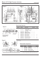
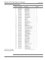
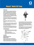
Model HP-15 High Pressure Lubricators
DESCRIPTION
The high pressure lubricator comprises one to six
integral sight and pump assemblies in a cast iron
reservoir. The unit is designed for direct connection to an
electric motor/speed reducer power source. A “Manzel”
terminal check valve is recommended in the lubrication
system. When required to maintain proper oil viscosity,
the reservoir can be fitted with an optional steam or
electric heater.
SPECIFICATION
Plunger Diameter .................................................... 1/4 Inch
Maximum Operating Pressure ............................ 18,000 psi
Maximum Pumping Rate ...... .008 in3 (0.133 cc) per stroke
Based on SAE 40 Oil — (approx. 4 drops)
Minimum Pump Rate .. .001 in3 (.017 cc) at max. pressure
Reservoir Heating (optional) ................... Stream or Electric
Lubricant Viscosity ................................... 100 to 5000 SUS
Operating Temperature ................................ -20OF to 120OF
OPERATING
Oil Level —
When necessary, completely fill the lubricator reservoir
with clean filtered lubricant. Three sight glasses, provided in the reservoir at various levels, permit observation
of fluid level. Oil level should not be allowed to drop
below the bottom sight glass. During the initial filling, the
vent plugs at the top of the pump sight glasses should
be removed. This allows lubricant to rise in the drip tube
up to the level of the oil in the reservoir and reduces the
priming required at start up.
Pump Priming —
If the sight well on the pump does not contain oil, the
pump should be primed. Pumps may be primed while
the lubricator shaft is rotating as follows:
a. Adjust the pumping rate to the maximum setting by
turning the adjustment nut on the indicator stem as
far as possible in a clockwise direction.
b. Remove the vent plug on top of the sight glass and fill
the housing sight well with oil to 3/8 inch below the
discharge of the drip tube.
c. Replace the vent plug. Check the sight glass to insure
that it is properly seated against the O-ring to prevent
air leakage into the sight well.
d. Readjust the pumping rate to the desired delivery.
Pumping Rate —
The pumping rate is indicated at the drip tube inside the
sight glass. During the pump suction stroke, fluid is
drawn into the pump from the sight well. This creates a
partial vacuum in the sight well, permitting atmospheric
pressure in the lubricator reservoir to force an amount of
oil equal to the pump displacement through the drip tube
into the sight well. The rate is adjustable for each pump
assembly by means of the pump regulator which varies
the stroke of the positive displacement, reciprocating
pump assembly.
Caution —
The drip tube flow rate is accurate after the pump has
operated long enough to stabilize the pressure inside the
sight well. There is a time lag at start-up, low pumping
rates, and during pump rate changes. Allow sufficient
time to insure an accurate rate indication.
Regulating Pump Rate —
The pumping rate can be varied infinitely within the range
of minimum to maximum by means of the graduated
pump regulators which project through the reservoir
cover. The regulators are easily adjusted by hand during
the pump suction stroke. Maximum pumping rate is
achieved when the adjustment nut on the sight indicator
stem is turned in a clockwise direction as far as it can
go. In this position the sight indicator stem projects the
maximum distance indicating maximum pumping stroke.
When the adjusting nut is turned in a counter-clockwise
direction, delivery reduces, because of a reduction in
pump stroke, until minimum delivery is obtained.
Note —
To retain the hydraulic seal between the plunger and the
cylinder walls, minimum delivery must not go below 1/2
drop, .001in3 (0.017 cc) per pump stroke.
Manzel® HP-15 High Pressure Lubricator
Bulletin 40230
Figure 1.
Check Valve Parts List
Figure 2.
Figure 3.
Figure &
Index No.
Part
Number
2-
463-280-001
2-
463-280-011
-1
-2
-3
-4
-5
-6
-6
-7
-8
-8
-9
463-920-000
463-910-000
458-005-130
439-007-010
463-860-880
446-010-010
446-010-010
463-860-870
446-000-010
446-000-010
446-055-000
Quantity
Required
Description
LINE CHECK VALVE ASSEMBLY,
3/8” O.D. Tube
DISCHARGE CHECK VALVE, .......
ASSEMBLY, 3/8” Tube
VALVE, Check
...................
SEAT, Check valve ...................
SPRING, Check valve ...................
GASKET, Check valve .................
BODY, Check valve ...................
NUT, Check valve
...................
NUT, Check valve
...................
BODY, Check valve ...................
COLLAR, Check valve .................
COLLAR, Check valve .................
NIPPLE, Check Valve ...................
Usage
Code
1
D
1
E
1
1
1
2
1
2
3
1
2
3
1
D
E
D
E
E
NOTE: This check valve for 3/8” tube. Other sizes available. Refer to factory for
parts list details.
Steam Heater Components
Figure &
Index No.
3-1
-2
-3
-4
-5
-6
Part
Number
Description
Quantity
Required
422-050-120
410-701-860
439-079-030
437-700-380
437-700-390
433-700-500
“O” RING SEAL
...................
SEAL NUT
...................
SEAL GLAND
...................
PLUG, 3/4” open
...................
PLUG, 1-1/4” open ...................
STEAM HEATER TUBE .................
2
2
2
1
1
1
NOTE: Steam and electric heaters available for all lubricators. Refer to
the factory for detail parts other than those shown above.
Page 2
Manzel® HP-15 High Pressure Lubricator
Bulletin 40230
HP-15 Lubricator Assembly Parts List
Figure &
Index No.
1-1
-2
-3
-4
-5
-6
-7
-8
-9
-10
-11
-12
-13
-14
-15
-16
-17
-18
-19
-20
-21
-22
-23
-24
-25
-26
-27
-28
-29
-30
-31
-32
1-33
-34
-35
-36
-37
-38
-39
-40
-41
-42
-43
-44
-45
-46
-47
-48
-49
-50
-51
-52
-53
-54
-55
*Site Glass Kit - 438-036-061.
Order this kit if your present
pumps have plastic site feeds.
Page 3
Part Number
469-838-091
471-638-030
469-838-030
402-040-120
402-114-320
402-114-330
423-010-160
422-012-270
419-150-090
419-150-060
419-150-040
412-130-160
453-030-130
410-700-730
453-040-050
411-700-270
402-172-040
418-010-140
484-110-020
418-090-230
439-077-110
438-010-030
465-920-030
542-847-000
473-040-131
457-008-321
412-140-060
412-140-040
457-002-232
438-028-060
409-010-290
471-680-090
415-110-060
362-390-325
477-140-100
463-160-071
477-020-511
458-005-140
422-040-120
410-700-750
484-170-020
422-042-120
422-040-180
411-700-260
458-005-200
475-070-010
484-010-110
438-036-070
433-700-020
433-701-153
503-485-000
422-042-130
437-700-770
418-010-360
410-701-840
422-041-120
473-020-471
Description
Quantity
Required
RESERVOIR ASSEMBLY ............................
· COVER, Reservoir ....................................
· BODY, Reservoir .......................................
· BEARING, Shaft ........................................
· BUSHING, Bearing .....................................
· BUSHING, Reservoir .................................
. SEAL, Shaft ..............................................
. “O” Ring Bearing .......................................
. SCREW, Cover end ...................................
· SCREW, Cover side ..................................
· SCREW, Bearing ........................................
. PLUG, Drain hole .......................................
. ROD, Feed adjusting .................................
. NUT, Feed adjusting ..................................
. LEVER, Actuating ......................................
. PIN, Lever ..................................................
. ROLLER, Pin ..............................................
. RING, Pin ....................................................
. SHOE, Lever .............................................
. RETAINER, Washer ...................................
. WASHER, Friction .....................................
. SIGHT GLASS, Reservoir .........................
. CRANKSHAFT ...........................................
. BREATHER ................................................
. FILLER ASSEMBLY ...................................
. NAMEPLATE ..............................................
. PLUG, 1-1/4” Heater opening ...................
. PLUG, 3/4” Heater opening .......................
. PLATE, Operating instructions ..................
. REFLECTOR, Gauge glass ........................
. KEY, Woodruff ..........................................
. COVER, Shaft end ....................................
. SCREW, Shaft end cover ..........................
. PUMP UNIT, HP-15 ...................................
. HOUSING, Pump ........................................
. VALVE ASSEMBLY ...................................
. CYLINDER ASSEMBLY .............................
. SPRING, Pump valve .................................
. GASKET, Valve .........................................
. NUT, Housing .............................................
. RETAINER, Spring ......................................
. “O” RING, Cylinder .....................................
. “O” RING, Cylinder .....................................
. PIN, Spring retainer ...................................
. SPRING, Plunger ........................................
. PUSHER, Plunger .......................................
. SLEEVE, Pusher ........................................
. SIGHT, Vacuum .........................................
. TUBE, Oil drip ............................................
. TUBE ASSEMBLY, Suction ........................
. PLUG .........................................................
. “O” RING, Vacuum sight ............................
. PLUG, Vent ................................................
. RETAINER, Housing ...................................
, NUT, Hold down ........................................
. “O” RING, Suction Tube ............................
. SUCTION STRAINER
(added to pumps made after 1/98) .........
REF.
1
1
2
2
2
2
2
4
8
4
1
6
6
6
12
6
24
6
6
6
3
1
1
1
1
1
1
1
3
1
1
1
6
1
1
1
1
2
1
1
1
1
1
1
1
1
1
1
1
1
1
1
1
1
1
1
SERVICE
Lubricator operation can be checked by observing the
drip tube. If the correct pumping rate is maintained, no
servicing is required other than periodic replenishment of
the reservoir. If the sight glass well pumps dry or no flow
is observed, check the following points until the cause is
determined and corrected.
a. Check the vent plug for proper sealing. Any
nicks or cracks in the rubber plug will cause
an air leak into the sight glass.
b. Check shaft rotation. If the lubricator shaft is
not rotating, determine the cause and repair
as necessary.
c. Check oil level and viscosity. Be sure the
reservoir is filled with oil, and if necessary
heat the reservoir to maintain viscosity at the
correct level for the desired flow.
d. Check pump priming. If necessary, prime the
pump in accordance with the “Operating
Instructions”.
e. Check the feed adjustment and readjust if the
pumping rate is too low.
f. Check the actuating linkage for proper
operation. If defective, isolate the broken part
and repair or replace as required.
If none of the above steps isolate the malfunction, the
cause is in the pump assembly. The following items
should be checked before removing the pump assembly
from the cover.
a. Check the sight for inward leakage due to a
crack in the sight glass, improper sight glass
seating, or a defective O-ring. Repair as
required.
b. Check for an obstruction in the drip tube and
remove if found.
If the above steps do not isolate the malfunction, disconnect the discharge tubing and remove the pump assembly which is attached to the cover with four screws.
Caution —
Exercise extreme care if equipment is operating.
Rotating equipment can cause serious injury. Faulty
pumps should be returned to the factory for repair as
they contain a selectively fitted cylinder and plunger. A
spare pump should be on hand for use during emergencies when a pump is being repaired.
If the sight glass fills with lubricant proceed as follows:
a. Remove the vent plug and allow the lubricant
to pump down to the proper level. Replace the
vent plug. The pump should operate normally.
b. If the sight glass continues to fill with
lubricant check all terminal check valves for
proper operation. If the valves are operating
properly, remove and clean the pump
assembly, then reinstall the pump in the
system and check operation.
c. If the sight glass still fills with lubricant it may
be caused by temperature variation.
1). When the unit is not operating,
remove the vent plug and allow the
lubricant to pump down to the proper
level. Replace the vent plug. The pump
will now function properly. The sight
glass may fill with fluid without affecting
the operation of the lubricator as long as
the drip tube remains above the
lubricant level to show the rate of
pumping.
2). When the unit is operating, the sight
level will vary depending on temperature
variations. If the level falls to less than 1/4
inch above sight glass flange, add
lubricant to the proper level (3/8 inch
below the discharge of the drip tube)
through the vent hole. If the level is too
high, remove the vent plug and allow the
unit to pump down before replacing the
vent plug.
Other servicing that may be required is listed below:
a. Periodic cleaning of the lubricator is desirable
to eliminate contamination that may have
occurred in the oil. To accomplish this,
remove all pumping units and clean the
pumps and reservoir by brushing loose all
foreign matter, dipping in solvent and
thoroughly drying.
b. If external leakage is observed, determine the
cause (loose bolts, defective gaskets, or
seals) and repair as required.
All written and visual data contained in this document are based on the latest product information available at the time of publication. Graco reserves the right to make changes at any time without notice
Call today for product information or to request a demonstration.
1.800.USA.LUBE (1-800-872-5823) or visit us at www.lubriquip.graco.com.
®2006 Graco Inc. Bulletin 40230, March 2002. Printed in U.S.A.
All other brand names or marks are used for identification purposes and are trademarks of their respective owners.