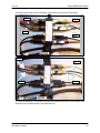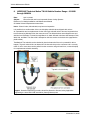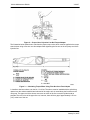
1
T. .P00 T.P . 50 Vehicle Maintenance Bulletin UNITED STATES POSTAL SERVICE VEHICLE MAINTENANCE MACK TRACTOR SERVICE RECALLS AND BULLETINS 1. Service Recall: SC312 Date: Vehicle Number Range: Subject: 9/14/06 6618268 through 6628334 Bulkhead-Mounted Air Manifold CXN and CHN Models Information: Mack Tractor has determined that a manufacturing defect exists in the bulkhead-mounted air manifold (part number 40QE54M) used on CV, CT, CL, CXN, and CHN model chassis manufactured between February 1, 2006, and May 15, 2006. Certain fittings could disengage from the manifold, resulting in air leaks and the unexpected application of the parking brakes. Approximately 8,800 chassis are involved. A list of affected vehicles has been sent to all applicable dealers. Procedures: The bulkhead-mounted air manifold must be replaced on all chassis models listed above. Note: Before proceeding, check the service status in the eWarranty system to see if the service has already been completed. You can also check service status by looking at the Campaign Completion Label located on the lower edge of the passenger-side door. If the service has been completed, the service number (SC312) and the completion date should be written on the label. Figure 1 Campaign Label Location Date: November 20, 2006 Number: V-01-07 Subject: Mack Tractor Service Recalls and Bulletins To: Managers, Operations Programs Support Attn: Managers, Vehicle Maintenance Managers, Vehicle Maintenance Facilities William W. Corey Manager Vehicle Operations Contents: 1. Service Recall: SC312 . . . . . . . . . . . . . . . 1 2. Service Recall: SC313 . . . . . . . . . . . . . . . 4 3. Service Bulletin: SB210040 . . . . . . . . . . . 5 4. Service Bulletin: SB214024 . . . . . . . . . . . 7 5. Optional Fifth Wheel Replacement Parts . . . . . . . . . . . . . . . . 13 6. Service Recall: Fleet Improvement Campaign, FI0456 Low Coolant Level Sensor Anti-capillary Jumper Harness . . . . . . 13 7. LUBRIQUIP Plumbing to Fifth Wheel . . . . . . . . 14 8. LUBRIQUIP Technical Notice TN-248 . . . . . . . . 16 Vehicle Maintenance Bulletin V-01-07 Procedures for replacing the air manifold are as follows: 1. Secure the chassis for service, apply the parking brakes, and block the wheels to prevent the vehicle from moving. 2. Completely drain the air system. 3. Open the hood. 4. Inside the engine compartment, disconnect the two bulkhead electrical connectors located directly above the air manifold, which is located on the left-hand side of the cab bulkhead. Position the harnesses in a location where they will not interfere with the remaining operation. It may be necessary to remove some of the tie wraps that secure the harnesses and air lines together. 5. The manifold includes five large and three small pass-through holes. Depending upon chassis equipment, the large holes are used for certain air connections such as the fifth wheel air control switch, power take off (PTO) control valve, or air suspension control valve. The three small holes are used for exhaust lines, and for the supply line from the pressure protection valve to the dashboard air switches. Push-to-connect bulkhead fittings are installed in the large holes when used for pass-through connections and closure plugs are installed in any unused holes. Figure 2 Air Manifold Pass-Through Connections Clearly mark the air lines to identify the air lines connected to each of the pass-through bulkhead fittings and then use the push-to-connect release tool (Weather-head part number 1800TRK) to disconnect the lines from the fittings. The lines must be clearly marked to ensure they are reconnected to the correct ports on the replacement manifold. 1. Disconnect the air line from the pressure protection valve located on the treadle valve. 2. Clearly mark the air lines to identify all the air lines connected to the air manifold fittings and then use the push-to-connect release tool to disconnect the air lines from the manifold. 3. On the inside of the cab, clearly mark the air lines to identify the air lines connected to the pass-through bulkhead fittings, and then use the push-to-connect release tool to disconnect the lines from the fittings. 4. Pull the dashboard air switch supply line through the manifold. 5. Clearly mark the air lines to identify all the air lines connected to the air manifold fittings and then use the push-to-connect release tool to disconnect the air lines from the manifold. 6. Mark the wires to identify those connected to the pressure switches and then disconnect the wires from the pressure switches mounted in the air manifold. 7. Remove the four mounting screws that secure the manifold to the cab. 2 November 20, 2006 V-01-07 Vehicle Maintenance Bulletin 8. Remove the air manifold by pushing the manifold into the cab from inside the engine compartment. A firm push may be required to loosen the manifold from the adhesive. 9. Clean any remnants of the seal and adhesive that may remain on the manifold mounting surface of the cab bulkhead. 10. Transfer the brass bulkhead fittings and closure plugs from the pass-through holes in the existing manifold to the same pass-through holes in the replacement manifold (part number 40QE54M). 11. Transfer any plugs from the existing manifold to the same ports in the replacement manifold as required. 12. Transfer the pressure switches from the existing manifold to the same ports in the replacement manifold. 13. Using the same mounting screws, install the replacement manifold in the cab. Before reconnecting the air lines, inspect the ends to ensure the lines are cut square and there are no burrs or other defects that may affect sealing. If the line ends are not in good condition, use an approved tubing cutter (such as Weather-head part number T919 or equivalent) to re-cut the lines. For information concerning push-to-connect air line fittings, refer to chapter 16, section 104 of the Air and Brake System Service Manual. 14. On the inside of the cab, feed the exhaust lines and the dashboard air switch supply line through the appropriate pass-through holes in the manifold. If desired, use MACK RTV Silicone Sealant (part number 342SX33) to seal the lines in the manifold. 15. Paying attention to the wire identification markings that were made in step 11, reconnect the wires to the air switches. 16. Reconnect the cab-side air lines to the correct manifold fittings and pass-through bulkhead fittings per the identification markings made previously. Gently tug on the air lines to ensure they are fully seated. 17. Inside the engine compartment, reconnect the dashboard air switch supply line to the pressure protection valve. 18. Reconnect the engine compartment-side air lines to the correct manifold fittings and pass-through bulkhead fittings per the identification markings that were made previously. Gently tug on the lines to ensure they are fully seated. 19. Reconnect the two bulkhead electrical connectors. 20. Using tie wraps, secure the air lines and wire harnesses as required to prevent rubbing and chafing. 21. Start the engine and build system pressure to governor cut-out (125–135 psi). 22. Stop the engine and then use a soap and water solution to check all manifold connections for air leaks. Correct leaks as required. 23. Close the hood and return the vehicle to service. Note: To signify that the service has been completed, use a permanent-type marker (such as a Sharpier) to write the campaign number (SC312) and completion date in the spaces provided on the Campaign Completion Label located on the lower edge (below the door latch) of the passenger-side door. If a label is not already affixed to the door, apply a label (part number TS897) and supply the information as required. Campaign Completion labels are available in packs of 50 and can be ordered by faxing a completed BR313 to Pacesetters Business Services at 610-264-9465. November 20, 2006 3 Vehicle Maintenance Bulletin V-01-07 Parts Required: Qty. 1 Part No. 40QE54M Description Air manifold, bulkhead mounted Removed Parts: Return the removed air manifold to the Technical Material Analysis Center. The minimum dollar value ($50.00 in the U.S. and $150.00 in Canada) for returned material is waived for this campaign. In the U.S., return the removed air manifold to: TECHNICAL MATERIAL ANALYSIS CENTER 4100 BOBWHITE BLVD PULASKI VA 24310 Reimbursement: Recover campaign expenses through normal warranty claim procedures. Enter the following information on the warranty claim: Qty. 1 Part No. 40QE54M Description Air manifold, bulkhead mounted Enter the service codes as follows: Failed Part (Causal Part) eWarranty Authorization No Labor Code/Allowance SC0312 SC0312 533 9A 00 95 — 0.2 hr. Time allowed to take charge of vehicle and check eWarranty system to determine campaign involvement. 533 9B 00 95 — 2.1 hrs. Time allowed to remove and replace bulkhead-mounted air manifold on CV, CT, CL, CXN, and CHN model chassis involved in this campaign. As required by Federal Motor Vehicle Safety Standards 49 CFR 573.11, no vehicle subject to an open safety campaign shall be delivered to the customer until such time as the defect or noncompliance is remedied. 2. Service Recall: SC313 Date: Vehicle Number Range: Subject: 08/04/06 6618268 through 6628334 Spring Brake Modulating Relay (Bendix SR-7) Valve Information: Bendix Commercial Vehicle Systems LLC has determined that a manufacturing defect exists in the cast metal body of certain spring brake modulating relay (SR-7t) valves. Suspect valves were manufactured by Bendix Commercial Vehicle Systems LLC between April 1, 2006, and May 24, 2006. The diameter of the check valve cavity inside the valve body is not correct. Consequently, the check valve may not seat properly and may result in internal leakage. An improperly seated check valve can cause a delay in the application of the parking brakes after the vehicle operator pulls the dashboard park brake valve to park the vehicle. The delayed application can occur without warning, leading to unintended vehicle roll-away. Affected vehicles include CXN, CHN, CTP, CT, CV, and MR model chassis (straight-trucks and tractors) manufactured between April 5, 2006, and June 5, 2006. Approximately 2,940 chassis are involved in this service recall. A list of affected chassis has been sent to all applicable dealers. Procedures: Inspect the SR-7 valve on all affected vehicles. If the date code pin stamped on the valve falls within the date range listed above and the casting is identified as “BENDIX 1”, the valve must be replaced. 4 November 20, 2006 V-01-07 Vehicle Maintenance Bulletin 3. Service Bulletin: SB210040 10/24/06 E6, E7, E9, ASET, E-Tech Engine Crankcase Blow-By Measurement Date: Model: In instances where the crankcase breather volume appears to be higher than normal, or if oil is expelled from the breather tube, first measure crankcase pressure. Note: On E-Techt and ASETt engines with a front timing cover mounted breather, oil may be expelled from the breather tube only, when the vehicle is operated on an incline with the front end much lower than the rear. If you encounter this condition, install the cylinder head cover topmounted breather and oil drain tube as described in SB214024. Before beginning the test, inspect the breather hose for blockage and clean or replace as required. Additionally, on E-Tech and ASET engines, remove the filter from the breather canister when you perform the test, and then clean and reinstall after you complete the test. Note: A plugged breather filter may be the result of an excessive blow-by condition. If the filter is found to be plugged with carbon, determine and correct the root cause of the excessive blow-by condition. Equipment Required Figure 3 Crankcase Blow-By Test Equipment Key Description 1 Rubber stopper (part number 8609-2198007)* 2 3/16I inside diameter plastic tubing, approximately 6 ft (2 M) 3 Differential pressure gauge such as Dwyer Magnehelic Model 2015 (which measures in the 0I to 15I of water range) ** 4 1/8I NPT x 3/16I hose barb fitting 5 1/8I NPT pipe plug * Rubber stopper is the correct size to fit inside the yellow dipstick adapter used on current E-Tech and ASET engines. For engine models that do not utilize the yellow dipstick adapter, short pieces of different diameter hose will be needed to connect the 3/16” ID hose to the dipstick tube. Hose diameter will vary depending upon which dipstick tube arrangement is installed on the engine. ** A water monometer can be used in place of the differential pressure gauge, but is much less convenient. November 20, 2006 5 Vehicle Maintenance Bulletin V-01-07 Preparing for the Blow-By Measurement Test Note: For engines equipped with the cylinder head cover-mounted breather, relocate the breather to the front timing cover to perform this test. Remove the closure plate from the mounting location on the front timing cover, and then relocate the breather canister (with the filter removed) from the cylinder head cover to the timing cover. Use the closure plate, Silastic sealant, and the existing mounting screws to seal the breather opening on the cylinder head cover. After you complete the test, relocate the breather canister to its original location on the cylinder head cover. Before measuring blow-by: 1. Install the 1/8I pipe plug into one of the high pressure ports of the Magnehelic test gauge and the hose barb fitting into the other high pressure port. The two low pressure ports will remain open. 2. Connect the 3/16I ID hose to the hose barb fitting. 3. Remove the dipstick from the dipstick tube, and then inspect the end of the tube to make sure it is not cracked nor has any other type of damage or defect that would result in blow-by leak-off. If the tube is defective, replace it. 4. Insert the 3/16I ID hose into the center hole of the rubber stopper, and then insert the stopper into the dipstick tube adapter. If the dipstick tube does not have the yellow adapter, use a short piece of hose having an inside/outside diameter as required to fit the 3/16I ID hose and the dipstick tube in order to connect the test gauge hose to the dipstick tube. 5. Place the test gauge inside the cab, making sure the hose is routed appropriately to prevent damage. Figure 4 Rubber Stopper with Tube Inserted into Dipstick Tube 6 November 20, 2006 V-01-07 Vehicle Maintenance Bulletin Perform the Blow-By Measurement Start the engine and run at no-load. After a brief warm-up, observe if excessive blow-by is present. Record the readings indicated on the test gauge at various engine speeds. During the no-load test, the gauge should indicate 2-1/2I of water or less. If readings are above 2-1/2I of water or oil is seen coming from the breather tube, no further tests are necessary, as the excessive blow-by condition is confirmed. Investigate the cause. If the test gauge readings are low and excessive blow-by is not evident, perform an under-load road test or a chassis dynamometer test. During a full-load road test (using as much load as can be obtained), record the test gauge readings at rated speed and peak torque speed (both ends of the engine operating range). If readings are above 2-1/2I of water, excessive blow-by is confirmed. Investigate the cause. If the test gauge readings do not exceed 2-1/2I of water, excessive blow-by is eliminated as the cause of the higher than normal crankcase pressure or oil being expelled from the breather tube. Causes of Excessive Engine Crankcase Blow-By If the above tests confirm the excessive crankcase blow-by condition, investigate the causes in the sequence listed below. The causes listed first are the most likely reasons for excessive blow-by and are the least costly with the least downtime for repair. Also consider vehicle mileage, type of service, and rate of oil consumption when attempting to determine the most likely causes. 1. Failed or leaking turbocharger seals, which allow boost pressure or exhaust pressure into the turbocharger oil drain tube and into the crankcase. 2. A disintegrated air compressor piston in a two-cylinder air compressor. 3. Worn or damaged valve stem seals or worn valve guides. 4. Worn piston rings and cylinder sleeves (particularly if the engine is experiencing excessive oil consumption). Worn piston rings, cylinder sleeves, or both may have been caused by dirt ingested by or dusting the engine. 4. Service Bulletin: SB214024 Date: Model: 10/24/06 ASET AI, ASET AMI, E-Tech Cylinder Head Cover-Mounted Breather and Oil Drain Tube A revised cylinder head cover-mounted breather kit (part number 57GC524A) has been developed for chassis equipped with ASET AI, ASET AMI, and E-Tech engines used in certain vocational operations (predominately concrete mixers and dump trucks) to prevent oil from spilling out the breather tube when the vehicle is either backing up or slowly descending a steep grade. This revised kit, which replaces the original kit (part number 57GC523), incorporates an oil drain tube which allows oil that can flood the front cylinder head cover to drain back into the oil pan. The kit includes all the components necessary to relocate the breather from the timing gear cover to the front cylinder head cover. The oil drain tube, which is different depending upon engine brake equipment, must be ordered separately. Refer to the illustration below and the accompanying parts table for a listing of the components contained in the kit. November 20, 2006 7 Vehicle Maintenance Bulletin V-01-07 Figure 5 Cylinder Head Cover-Mounted Breather Relocation Kit and Drain Tube Cylinder Head Cover-Mounted Breather Relocation Kit (Kit Part number 57GC524A) Key 1 2 3 4 5 6 7 8 9 10 11 12 13 14 15 16 17 18 8 Qty. 1 3 1 6 1 2 4 1 1 1 1 1 1 1 1 1 1 1 1 Part No. Description 85111052 Hose, size No. 16, 9I (229 mm) long 83AX1049 Hose clamp, size No. 24 332GB264 Closure plate 66AM44 Screw, M8 x 1.25 x 16 mm long, full thread 477GB530 Oil filler tube with spud for oil drain tube 744GB248 Hose, foil-wrapped 83AX838 Hose clamp, size No. 16 180GB267 Clamp, breather tube 253GC3212M Bracket, breather tube, upper mounting 66AM6 Screw, M10 x 1.5 x 20 mm long, full thread 63AX4112 Fitting, 45-degree push-on type hose 337GB549AM Cylinder head cover, front 49AX278 Closure plug, J-Techt-equipped or non-brake engines QE2182 Connector, MACK PowerLeasht-equipped engines 160AX543P3 Hose, size No. 16, 3I (76 mm) long 238GC528 Tube, breather 253GC476M Bracket, breather tube, lower 83AX827 P-clamp, cushioned 26AM1 Screw, M6 x 1.0 x 14 mm long, full thread November 20, 2006 V-01-07 Vehicle Maintenance Bulletin The drain tube is not included with the kit and must be ordered separately depending upon whether the engine is a non-brake or PowerLeasht-equipped engine, or equipped with a J-Tech engine brake. Part numbers are as follows: Key 19 Qty. 1 1 Part No. 681GC545 681GC546 Description Oil drain tube, non-brake or PowerLeash-equipped engines Oil drain tube, J-Tech-equipped engines In addition to the parts listed in the tables above, the following additional items will be required. Qty. 1 1 Part No. 56AX594 342SX33 Description O-ring, turbocharger drain tube Silastic sealant Note: If it is necessary to replace the cylinder head cover gasket, use gasket part number 554GB321. (The cylinder head cover gasket is reusable and should be replaced only if damaged or is no longer soft and pliable.) Procedures for installing the cylinder head cover-mounted breather and the oil drain tube are as follows: 1. Remove the clamp and bracket that secure the existing breather hose to the oil pan mounting stud, and then remove the breather hose from the breather canister. Figure 6 Remove Breather Hose 2. Remove the breather canister from the timing gear cover. Note: Remove the cover from the canister and then thoroughly clean the mesh filter and the inside of the canister. 3. Clean the area of the timing gear cover around the breather opening, and then apply a bead of Silastic sealant (part number 342SX33) around the edge of the closure plate (part number 332GB264) and to the threads of the mounting screws (part number 66AM44). Install the closure plate to the timing gear cover and tighten the screws to 15 lb-ft (20 N-m). 4. Install the 45-degree hose fitting (part number 63AX4112) into the opening on the right-hand side of the new cylinder head cover (part number 337GB549AM). On J-Tech-equipped engine brakes, orient the fitting so it faces the rear and is 30 degrees off the vertical centerline. For non-brake or PowerLeash-equipped engines, orient the fitting so it faces the rear and is 45 degrees off the vertical centerline. November 20, 2006 9 Vehicle Maintenance Bulletin V-01-07 Figure 7 Hose Fitting Orientation in Cylinder Head Cover 5. If equipped with a PowerLeash engine brake, install the electrical pass-through connector (part number 40QE2182) into the opening on the left-hand side of the cylinder head cover. For non-brake or J-Tech-equipped engines, install the plug and O-ring (Part number 49AX278) into the opening. 6. Remove the existing front cylinder head cover. 7. Install the new cylinder head cover. Reuse the existing cylinder head cover gasket and mounting screws. Tighten the mounting screws to 16 lb-ft (22 N-m). 8. After making sure the breather canister mounting flange is clean and oil free, apply a bead of Silastic sealant (part number 342SX33) around the flange and then install the canister to the cylinder head cover using the same screws originally used to secure the canister to the timing gear cover. Tighten the screws to 15 lb-ft (20 N-m). 9. Remove the existing oil fill tube, and then remove and discard the O-ring from the bottom of the turbocharger oil drain tube. 10. Install a new O-ring (part number 56AX594) to the bottom of the turbocharger oil drain tube. 11. Clean the oil fill tube mounting surface on the side of the cylinder block. Apply a bead of Silastic sealant (part number 342SX33) around the edge of the mounting flange on the new oil fill tube (part number 477GB530). Install the new oil fill tube by carefully aligning and then inserting the turbocharger drain tube into the drain spout in the oil fill tube. Use the existing screws to secure the oil fill tube to the cylinder block, and tighten the screws to 15 lb-ft (20 N-m). 12. Slide a hose clamp (part number 83AX838) over each end of the short coupling hoses (part number 744GB248), and then install the hoses onto each end of the oil drain tube (part number 681GC545 for non-brake or PowerLeash-equipped engines or part number 681GC546 for J-Tech-equipped engines). 13. Install the oil drain tube to the stud on the oil fill tube and the hose fitting on the cylinder head cover. Tighten the hose clamps to 27.5 lb-in (3.1 N-m). 14. Using two cap screws (part number 66AM44), install the breather tube lower mounting bracket (part number 253GC476M) to the side of the cylinder block. Do not tighten the screws at this time. 10 November 20, 2006 V-01-07 Vehicle Maintenance Bulletin Figure 8 Installing Breather Tube Lower Mounting Bracket Key 1 2 Qty. 2 1 Part No. 66AM44 253GC476M Description Screw, M8 x 1.25 x 16 mm long Bracket, breather tube mounting, lower 15. Install the breather tube upper mounting bracket (part number 253GC3212M) on the boss located at the front of the exhaust manifold. Use a new screw (part number 66AM6), but do not tighten the screw at this time. Note: On RD models equipped with air conditioning, the tie bracket for the air conditioning compressor is secured to the boss on the exhaust manifold. Remove the existing tie bracket mounting screw and install the breather tube mounting bracket on top of the tie bracket. Use screw part number 66AM6. Figure 9 Installing Breather Tube Upper Bracket Key 1 2 November 20, 2006 Qty. 1 1 Part No. 66AM6 253GC3212M Description Screw, M10 x 1.50 x 20 mm long Bracket, breather tube mounting, lower 11 Vehicle Maintenance Bulletin V-01-07 16. Install a short coupling hose (part number 160AX543P3) to the upper end of the breather tube (part number 238GC528) and secure with a hose clamp (part number 83AX1049). 17. Slide the cushioned P-clamp (part number 83AX827) onto the lower end of the breather tube, and then install the 9” (229 mm) section of hose (part number 85111052). Secure the hose to the tube with a hose clamp (part number 83AX1049). 18. Connect the breather tube assembly to the breather canister and secure with a hose clamp (part number 83AX1049). Figure 10 Breather Tube Upper and Lower Mounting Brackets Key 1 2 3 4 Qty. 2 1 1 1 Part No. 66AM44 180GB267 26AM1 83AX827 Description Screw, M8 x 1.25 x 16 mm long Clamp, breather tube mounting, upper Screw, M6 x 1.0 x 14 mm long P-clamp, cushioned 19. Secure the breather tube to the upper mounting bracket with a clamp (part number 180GB267) and two screws (part number 66AM44), and secure the cushioned P-clamp to the lower mounting bracket with a screw (part number 26AM1). 20. Tighten the upper and lower mounting bracket screws, and the clamp mounting screws to 15 lb-ft (20 N-m). Mack Trucks, Inc. engages in a continuous program of testing and evaluating to provide the best possible product. Mack Trucks, Inc., however, is not committed to, or liable for updating existing chassis. If you would like to receive the Mack Truck Service Bulletin via e-mail, go to http://www.macktrucks.com/default.aspx?pageid=131, insert your email address, select Subscribe, and click Submit. You may also unsubscribe to the service by providing your e-mail address, selecting Unsubscribe, and clicking Submit. Please review the Mack Privacy Statement for important information. Note: The Mack engine model referenced are described in Vehicle Maintenance Bulletin V-07-06. The model numbers are as follows: Cab Over Engine Cab Behind Engine 12 Model: AI-350 ASET Model: AC-330/350 ASET November 20, 2006 V-01-07 Vehicle Maintenance Bulletin 5. Optional Fifth Wheel Replacement Parts Note: The local transportation offices have authorization from Surface Operations in Headquarters to replace the hydraulic fifth wheels as needed. The transportation manager must notify the area Postal Vehicle Service (PVS) analyst of the decision to change the equipment prior to the conversion. The following list of components is required to convert the hydraulic fifth wheel to a fixed unit. Mack Truck Dealers have the discounted pricing in their system. Vehicle maintenance facilities may go to any Mack dealer to purchase the parts. The required parts are listed below. FW35-S10770 STATIONARY ASSEMBLY XB-10759-12 ASSY, 12 VOLT 2 SENSOR REMOTE XB-10760-V WARNING LIGHT MODULE, 3 POSITION XB-10781 EXT. CABLE, 2 SENSOR CHASSIS XB-10782 EXT. CABLE, 2 SENSOR CAB Note: Use PS Form 969, Material Recycling and Disposal, to sell or dispose of the Holland Hydraulic fifth wheels. The Holland fifth wheels were a costly option on the Mack Tractors. Every attempt to recover funds should be exercised. Vehicle Operations has several contacts that have inquired about purchasing the fifth wheels. If you need the contact information, send an email to Kirby Cothren at [email protected] or Mark Long at [email protected]. 6. Service Recall: Fleet Improvement Campaign, FI0456 Low Coolant Level Sensor Anti-capillary Jumper Harness Vehicle Number Range: 6618268 through 6628334 Vehicle Type: CXN A coolant level sensor that is leaking internally can result in damage to the engine electronic control unit (EECU) due to “wicking” or migration of the liquid down the harness. An anti-capillary jumper harness (41MR31560M) has been made standard as a running change in production. This harness needs to be installed on the chassis on the attached list, as they were built before the harness was introduced. The 41MR31560M harness was installed at the NRV plant on some chassis prior to being shipped or in a previous repair. Prior to initiating installation of the 41MR31560M harness, check if FI456 is written on the driver’s side of the coolant surge tank. If FI456 is written on driver’s side of the coolant surge tank, this fleet improvement has been completed. Return the chassis to service. If FI456 is not written on the tank, follow the instructions below. Installation of the 41MR31560M anti-capillary harness Remove the J1 connector from the EECU by pulling back on the connector lock and gently pulling the connector back on its heel. Check inside the connector for coolant and also check the pins on the EECU for signs of corrosion. If the pins are corroded, replace the EECU. Contact your Mack dealer for EECU replacement. November 20, 2006 13 Vehicle Maintenance Bulletin J1 Connector V-01-07 Low Coolant Level Sensor If no coolant or corrosion is found, remove the harness connector from the low coolant level sensor and connect the jumper harness to the coolant level sensor. Loop the excess harness and use tie wraps to secure the loop. Connect the other end of the jumper harness to the engine harness. Using a yellow or white paint stick, write PI456 of the driver’s side of the coolant surge tank to designate this repair has been completed. Claim Information For Mack Warranty claims, use primary labor code 273EB2393 and enter 0.3 hours. Take charge time can be added, if applicable. Use failed part number FI0456. For e-warranty claims, use labor code 273EB2393 and enter 0.3 hours. Take charge time can be added, if applicable. Use causal/failed part number FI0456 and enter claim type as Service Program. The FI0456 service program will expire December 31, 2006. 7. LUBRIQUIP Plumbing to Fifth Wheel Vehicle Number Range: 6618268 through 6628334 Check the lube fittings to the fifth wheel for proper routing. Reports have been received that the lube lines for the pivots and the rear plate lube ports are reversed. If the lines are improperly plumbed, the pivots will be over greased and the rear lube ports will not get enough grease. 14 November 20, 2006 V-01-07 Vehicle Maintenance Bulletin The photos below show the lines improperly routed (before) and properly routed (after). Blue Blue Black Black Black Black Blue Blue To correct the plumbing, reverse both of the blue and the black lube lines for the 5th wheel at the distribution block located inside the right side frame rail. November 20, 2006 15 Vehicle Maintenance Bulletin V-01-07 8. LUBRIQUIP Technical Notice TN-248 Vehicle Number Range: 6618268 through 6628334 Date: Subject: April 12, 2006 New solenoids used on air-operated Grease Jockey Systems Reference: GJ-30050 Installation and Maintenance Manual GJ-30020 Solenoid Replacement Instructions Issue: Solenoid valve, 550-250-266, may become inoperative It is possible for a small number of the new Lubriquip solenoid valves shipped with various air–operated kits and as replacements for the older style solenoid valve to become inoperative due to wires becoming dislodged from the connector end. The affected valves were shipped loose and with kits from December 13, 2005, through March 15, 2006. Affected units have date stamps of V05, W05, X05, and M06. This date code is stamped on the blue section on the back side (opposite the plastic elbow). Test Method: The solenoid can be checked by hand to determine if there is a potential for this to happen. Tug each solenoid wire to determine if the internal crimp on the connector end is correctly made. If one or more wires can be pulled from the connector using minimal force, contact Lubriquip for a replacement solenoid assembly. Support: Questions about this procedure should be directed to Grease Jockey Application Engineering at 1-800-USA-LUBE ext 4258 or [email protected] 16 November 20, 2006 T. .P00 T.P . 50 Vehicle Maintenance Bulletin UNITED STATES POSTAL SERVICE VEHICLE MAINTENANCE APPROVED LUBRICANTS AND COOLANTS FOR TWO TONS, CARGO VANS, TRACTORS, AND SPOTTERS Date: December 8, 2006 Number: V-03-07 Subject: Several questions have arisen concerning approved lubricants and coolants for heavy duty vehicles. The following information clarifies the requirements for servicing our heavy duty fleet. Approved Lubricants and Coolants for Two Tons, Cargo Vans, Tractors, and Spotters To: Note: This information is not intended to be all-inclusive, but to provide guidance when choosing products for servicing our heavy duty fleet. Managers, Operations Programs Support Attn: Managers, Vehicle Maintenance Heavy Duty Original Equipment Manufacturer Lubricants and Coolants Managers, Vehicle Maintenance Facilities Engine Oils Freightliner and International cargo van models require an American Petroleum Institute (API) rated CI-4 or higher 15W40 engine oil. Although CJ-4 engine oils are required for 2007 low emission rules, Postal Service vehicles are currently not required to meet that rule. Alternatively, Mack provides a list of approved engine oils meeting their tractor requirements (see Appendix A). Re-refined motor oil with a CI-4 rating is appropriate for the cargo vans and is also included on the Mack approved list. The API motor oil guide and Mack approved oil list are attached as a reference (see Appendix A). Note: Re-refined motor oil should be considered as the first choice if it meets the original equipment manufacturer’s (OEM) specifications. William W. Corey Manager Vehicle Operations Contents: Engine Oils . . . . . . . . . . . . . . . . . . 1 Engine Coolants . . . . . . . . . . . . . 1 Transmission Fluid . . . . . . . . . . . 2 Engine Coolants API Certifications . . . . . . . . . . . . . 2 With the exception of the 2006 Capacity Spotters, vehicles purchased within the last three years were delivered with extended life coolant (ELC). As with ethylene glycol type coolants, ELC for heavy vehicles has different characteristics than light duty coolants. While Dexcool is a General Motors-approved passenger car coolant and can be used in diesel engines that don’t have wet sleeve liners (such as light-duty trucks), Dexcool does not contain molybdates or nitrites to prevent cavitation in wet sleeve liners. Texaco ELC HD has molybdates and nitrites for cavitation control in wet sleeve liners. This is the product approved by most heavy duty truck manufacturers for their coolant systems. Product sheets for both Texaco and Dexcool are listed in Appendix B. Appendix A . . . . . . . . . . . . . . . . . . 4 Appendix B . . . . . . . . . . . . . . . . . . 6 Appendix C . . . . . . . . . . . . . . . . 14 Vehicle Maintenance Bulletin V-03-07 Transmission Fluid Vehicles equipped with the Allison transmission are delivered from the factory with TranSynd synthetic fluid. As long as TranSynd or a fluid meeting TES 295 rating is used exclusively in tractors, the transmission fluid should be changed every 150,000 miles. When using non-TranSynd or TES 295 transmission fluid, the transmission fluid must be changed on a 25,000 mile interval. In most cases the extended change interval far outweighs the extra cost or inconvenience of using a non-recommended transmission fluid. (See Appendix C for more information on the Allison transmission.) API’s Service Symbol and Certification Mark Oil containers displaying the following marks meet performance requirements set by U.S. and international vehicle and engine manufacturers and the lubricant industry. More than 500 companies worldwide participate in this voluntary program, which is backed by a marketplace sampling and testing program. 1. Starburst Oil containers displaying this mark meet the current engine protection standard and fuel economy requirements of the International Lubricant Standardization and Approval Committee (ILSAC), a joint effort of U.S. and Japanese automobile manufacturers. Most automobile manufacturers recommend oils that carry the API Certification Mark. 2. API Service Level Oils designed for gasoline engines — including cars, vans, and light trucks — fall under API’s “S” (Service) categories. Oils designed for diesel-engines — including heavy-duty trucks and other vehicles with diesel engines — fall under API’s “C” (Commercial) categories. 3. SAE — Viscosity Grade Viscosity is the measure of an oil’s thickness and ability to flow at certain temperatures. Vehicle requirements may vary. Follow your vehicle manufacturer’s recommendations on Society of Automotive Engineers oil viscosity grade. 4. Energy Conserving The “Energy Conserving” designation applies to oils intended for gasoline-engine cars, vans, and light trucks. Widespread use of “Energy Conserving” oils may result in an overall savings of fuel in the vehicle fleet as a whole. 2 December 8, 2006 V-03-07 Vehicle Maintenance Bulletin 5. CI-4 PLUS Used in conjunction with API CI-4, the “CI-4 PLUS” designation identifies oils formulated to provide a higher level of protection against soot-related viscosity increase and viscosity loss due to shear in diesel engines. Like Energy Conserving, CI-4 PLUS appears in the lower portion of the API Service Symbol “Donut.” Multi-grade oils such as SAE 5W-30 and 10W-30 are widely used because, under all but extremely hot or cold conditions, they are thin enough to flow at low temperatures and thick enough to perform satisfactorily at high temperatures. December 8, 2006 3 V-03-07 Vehicle Maintenance Bulletin Appendix A Mack Trucks Approved EO-O Premium Plus Engine Oils (Issued 11-7-2006) Note: It is the responsibility of each oil company to ensure its respective brand names comply with the EO-O Premium Plus specification. 4 OIL COMPANY EO-O PREMIUM PLUS BRAND NAME VISCOSITY Mack Trucks, Inc. Volvo Trucks, N.A. Bulldog EO-O Premium Plus Volvo Premium Motor Oil 15W40 15W40 Advanced Lubrication Specialties, Inc. American Refining Group Inc. Benz Oil Company Cam2 Oil Products Co. Castrol Ltd. Caterpillar, Inc. Chevron Global Lubricants Chevron Global Lubricants Chevron Global Lubricants CITGO Petroleum Corp. CITGO Petroleum Corp. Conoco Phillips Conoco Phillips Conoco Phillips D-A Lubricant Co. David Weber Oil Co. David Weber Oil Co. David Weber Oil Co. Dennis K. Burke Inc. Gulf Oil Limited Partnership KOST USA Mack Trucks, Inc. Mobil Branded Lubricants, Exxon Mobil Corp. Northland Products Co. Petro-Canada Lubricants Petro-Canada Lubricants Safety-Kleen Corp. Safety-Kleen Corp. Shell Canada Products Ltd. Shell International Petroleum Co., Ltd. Shell International Petroleum Co., Ltd. Shell International Petroleum Co., Ltd. U.S. Oil Co., Inc. Ultramar Ltd. Universal Lubricants, Inc. Valvoline, Inc. (Sub. of Ashland Oil, Inc.) Volvo Trucks N.A. Advantage 15W-40 CJ-4 Premium Plus Brad Penn H.D. Premium Plus Diesel XT Cam2 Super HD Premium Plus (07) Castrol Hypuron CAT DEO-ULS Chevron Delo 400 LE Chevron RPM LA Texaco Ursa Premium TDX EC Citgard 700 Mystic JT-8 EMT Fleet Supreme EC Guardol ECT Kendall Super-D XA Reliant J-4 Gibraltar Super S-3 LDLX Gibraltar Super S-3 LX Gibraltar Ultra LX Fleetline Superfleet Gulf Super Duty Plus Toughinal HD Bulldog EO — O Premium Plus Mobil Delvac 1300 Super Superline Duron-E Duron-E XL America’s Choice XHD-7 Performance Plus XHD-7 Shell Rotella T Pennzoil Long Life Gold Shell Rimula Super Shell Rotella T Diesel Supreme CJ-4 Mack Ultramar Quest Dyna-Plex 21C Durazol HC 15W40 Premium Blue Volvo Premium Motor Oil 15W40 15W40 15W40 15W40 15W40 15W40 15W40 15W40 15W40 15W40 15W40 15W40 15W40 15W40 15W40 15W40 15W40 15W40 15W40 15W40 15W40 15W40 15W40 15W40 15W40 15W40 15W40 15W40 15W40 15W40 15W40 15W40 15W40 15W40 15W40 15W40 15W40 December 8, 2006 V-03-07 Vehicle Maintenance Bulletin Which oil is right? The current API Service Categories are listed below. Fleet vehicle owners should refer to their owner’s manuals before consulting these charts. Oils may have more than one performance level. For automotive gasoline engines, the latest engine oil service category includes the performance properties of each earlier category. If an automotive owner’s manual calls for API SJ or SL oil, API SM oil will provide full protection. For diesel engines, the latest category usually includes the performance properties of an earlier category. Diesel Engines Category CI-4 Status Current Service CI-4 oils, which were introduced in 2002 are intended for use in high-speed, four-stroke engines designed to meet 2004 exhaust emission standards implemented in 2002. CI-4 oils are formulated to sustain engine durability where exhaust gas recirculation (EGR) is used and are intended for use with diesel fuels ranging in sulfur content up to 0.5% weight. The oil can be used in place of CD, CE, CF-4, CG-4, and CH-4 oils. Some CI-4 oils may also qualify for the CI-4 PLUS designation. CH-4 Current CH-4 oils, which were introduced in 1998, are intended for use in high-speed, four stroke engines designed to meet 1998 exhaust emission standards. CH-4 oils are specifically compounded for use with diesel fuels ranging in sulfur content up to 0.5% weight. The oil can be used in place of CD, CE, CF-4, and CG-4 oils. CG-4 Current CG-4 oils, which were introduced in 1995, are intended for use in severe-duty, high-speed, four-stroke engines using fuel with less than 0.5% weight sulfur. CG-4 oils are required for engines meeting 1994 emission standards and can be used in place of CD, CE, and CF-4 oils. CF-4 Current CF-4 oils, which were introduced in 1990, are intended for use in high-speed, four stroke, naturally aspirated and turbocharged engines. December 8, 2006 5 V-03-07 Vehicle Maintenance Bulletin Appendix B Extended Life Antifreeze/Coolant Maintenance technology and methods for light duty and heavy duty vehicles are constantly changing. One of these technological changes involves the antifreeze/coolant available for use in cooling systems. A new type of antifreeze, referred to as extended life or long life, is now available. The chemistry used in this product is unique and very different from that used in traditional antifreezes. This difference requires a significant change in the maintenance procedures used to maintain cooling systems when extended life antifreeze is utilized. The total maintenance package offered by the use of extended life antifreeze is directed at extending total cooling system drain intervals to 300,000 miles, 6,000 hours or four years, whichever comes first. Since this doubles all existing engine manufacturers’ current recommendations, VMFs must adhere to some specific maintenance practices in order to realize the benefits of extended life antifreeze. Extended life antifreezes are available in both ethylene and propylene glycol bases. These are packaged either undiluted or pre-mixed 50/50 with water. Of specific interest is the corrosion inhibitor additive package used in the extended life antifreezes. Its major ingredient is an organic acid. Because of the organic acid additive package and some other chemical characteristics of extended life antifreeze, the depletion of the corrosion inhibitors is very different from coolants utilizing traditional supplemental coolant additives (SCAs). While coolants using current SCAs require the SCA level to be replenished on a routine basis, coolants using extended life antifreeze require inhibitor package replenishment only once during its service life. The inhibitor additive for extended life antifreeze is not an SCA style package. Use only a special formulation additive package with extended life antifreezes. Do not substitute the current formulation SCA package or the special extended life package for each other at any time. Although extended life antifreeze is chemically compatible with traditional formulation antifreezes, it is the recommendation of all extended life antifreeze manufacturers and suppliers that the two types not be mixed. Mixing the two types of antifreezes completely negates any extended life characteristics. For this reason, extended life antifreezes have been colored red and orange depending on the supplier. Other colors may appear in the future. Top-off and refill extended life antifreeze only with the appropriate products. Further, if a coolant recycling program is being used, segregate the extended life antifreezes from the traditional antifreezes and review the recycling process. Also, review the original antifreeze manufacturer’s recommendations for recycling. Note: The following products are listed as examples and not as an endorsement of specific vendors. Please reference the original manufacturers’ suggested coolant/anti-freeze recommendations. 6 December 8, 2006 V-03-07 Vehicle Maintenance Bulletin Extended Life Coolant Anti-Freeze Examples Texaco Extended Life Coolants The following is a list of Texaco extended life coolants: Texaco Extended Life Coolant System CPS 227997 (MSDS 10300) Texaco Extended Life Coolant/Anti-Freeze is a single-phase, ethylene glycol type heavy duty diesel engine coolant based on Texaco’s enhanced and patented extended life organic corrosion inhibitor system with nitrite and molybdate added. This product is recommended for freeze point adjustment and initial fill. (Dilute using 50% water and 50% anti-freeze.) H Texaco Extended Life Prediluted 50/50 Coolant/Anti-freeze CPS 227998 (MSDS 10309) Texaco Extended Life Pre-diluted 50/50 Coolant/Anti-Freeze is a 50/50 mixture of Texaco Extended Life Coolant/Anti-Freeze with de-ionized water. Texaco ELC 50/50 can be used for initial fill or top up. H Texaco Extender CPS 227999 (MSDS 10317) Texaco Extender is the prescribed recharge for Texaco Extended Life Coolant/Anti-Freeze. It should be used to extend service life to 1,000,000 miles/20,000 hours/8 years. Extender should be added at 500,000 miles/10,000 hours/4 years. Product Application Extended Life Coolant System is a heavy-duty, ethylene glycol based engine coolant system which incorporates patented organic corrosion inhibitor technology. The Texaco ELC formula has been recently enhanced to provide longer service life, enhanced corrosion protection, and lower electrical conductivity. Extended Life Pre-diluted 50/50 Coolant/Anti-Freeze meets American Society of Testing and Materials (ASTM) D 6310 and D 3306. Texaco ELC is a nitrate-, borate-, phosphate-, silicate-, and amine-free formulation, which uses Texaco’s patented carboxylate technology to provide maximum protection of the six basic metal alloys found in most heat transfer systems. Since the coolant contains no phosphates or silicates, hard water deposits in the cooling system are reduced. Water pump seal wear is reduced as a result of fewer abrasive dissolved solids in Texaco Extended Life Coolant and that results in improved water pump seal life. The newly enhanced formula and patented carboxylate corrosion inhibitors in Texaco Extended Life Coolant/Anti-Freeze have been shown to remain at effective levels up to 750,000 miles/15,000 hours/8 years with no addition of Extender needed. Note: These products are not to be used to protect the inside of potable water systems against freezing. How to Convert to Texaco Extended Life Coolant Conversion to extended life coolant can be accomplished by using one of three methods. 1. The first method is to completely drain the coolant in service, flush the entire cooling system, and refill the cooling system with a fresh dose of Texaco Extended Life Coolant/Antifreeze as per manufacturers’ recommendations. 2. The second recommended method for conversion to Texaco ELC is during a drain of the old coolant and a refill of the cooling system with a fresh dose of Texaco ELC Pre-diluted 50/50. When using this method about 10% of the old coolant will remain in the system and this should be taken into consideration since Delo ELC is tolerant to dilution with other coolants up to 25%. December 8, 2006 7 V-03-07 Vehicle Maintenance Bulletin 3. The third recommended method for conversion is to use FleetFix Conversion. Fleet Fix Conversion is part of a complete program that will allow conversion of conventional coolant that is in acceptable condition to extended life coolant without the need to drain the present coolant in use. The first and second methods should carefully follow the OEM’s recommended procedure. Users desiring to use Fleet Fix Conversion should consult their local Texaco distributor for information. Do not add traditional coolants or SCAs to Texaco Extended Life Coolant/Anti-Freeze products, since doing so will reduce the extended life benefits. Benefits The following is a list of the benefits of extended life coolant/anti-freeze: 1. 750,000 miles on-road use (8 years or 15,000 hours off-highway use) on initial fill with no Extender needed. 2. Additional extended service life of 1,000,000 miles/20,000 hours/8 years with Extender added at 500,000 miles/10,000 hours/8 years. 3. Improved corrosion protection and lower electrical conductivity. 4. Reduced maintenance and related costs. 5. No addition of supplemental coolant additives (SCAs) needed. 6. No inhibitor testing required. 7. Excellent protection against pitting, corrosion, and erosion even on hard-to-protect metals like aluminum. 8. Excellent heat transfer compared to silicate containing coolants. 9. Improved water pump life due to no silicate formula. 10. Excellent protection for all heavy-duty engines including engines using EGR and ACERT technology. 11. Protection against winter freeze-up and summer boil-over. 12. Biodegradable in its unused form. 13. Outstanding hot surface aluminum protection. 14. Suitable for gasoline-powered automotive and industrial engines. 15. Compatible with conventional antifreeze. Dilution with conventional antifreeze will reduce extended life benefits. Texaco recommends that this product not be diluted by more than 25% with conventional coolants. Product Recommendations and Approvals Texaco Extended Life Coolant System is recommended for all heavy-duty engines using all fuel types including engines manufactured by Caterpillar, International, Cummins, Detroit Diesel, Mack, John Deere, JI Case, Ford, General Motors, Volvo, and others. Texaco Extended Life Coolant System is recommended for use in the cooling systems of all types of industrial internal combustion engines. Texaco Extended Life Pre-diluted 50/50 Coolant/Anti-Freeze and Texaco Extended Life Coolant/Anti-Freeze meet or exceed: 1. ASTM D 6210 2. ASTM D 3306 3. TMC RP 329, 302A, 351 (color) 4. Phosphate-free requirement of European OEMs 8 December 8, 2006 V-03-07 Vehicle Maintenance Bulletin 5. Silicate-free requirement of Japanese OEMs 6. CF-4 oils, which were introduced in 1990, are intended for use in high-speed, four stroke, naturally aspirated and turbocharged engines. Caterpillar EC-1 7. Navistar B1 Product Technical Data Texaco ELC exhibits a lower reserve alkalinity and lower pH when compared to traditional phosphate and borate containing coolants. These differences are due to the unique inhibitor package used in Texaco ELC and do not in any way compromise corrosion protection. ASTM has recognized that RA is not an indicator of corrosion protection effectiveness and has removed all RA requirements for coolant/antifreeze products. A comparison of Texaco Extended Life Coolant/Anti-Freeze with traditional coolants is shown below. Texaco Extended Life Coolant has lower pH and RA relative to traditional coolants. The pH change profile in service is a more important performance measure than the RA level. Texaco Extended Life Coolant/Anti-Freeze shows a typical pH reduction of less than 1.5 units in 160,000-kilometer fleet tests compared with a pH reduction of up to 3 units for traditional coolants. The freeze point of a coolant is a measure of how low the fluid’s temperature can go before it freezes. The ratio of glycol and water in an antifreeze/coolant will determine the freeze point. The easiest and most accurate way to measure freeze point is by using a refractometer. The freeze point of Texaco ELC should be maintained between -12°F (-37°C) and -62°F (-57.7°C). Boiling and Freezing Protection for Texaco Extended Life Coolant/Anti-Freeze Because this product is silicate free, Texaco Extended Life Coolant/Anti-Freeze and Texaco Extended Life Pre-diluted 50/50 Coolant/Anti-Freeze can be stored at least 8 years with no problem provided the container integrity is maintained. Always dispose of used coolant in accordance with local, state, provincial, and federal guidelines. How to Maintain Texaco ELC There are three simple steps to maintaining Texaco Extended Life Coolant while in service: 1. At every PM, check the coolant color and insure the product is bright red and contains no debris or oil. 2. Test the freeze point of Texaco ELC at least two times per year. Maintain freeze point between -12°F and -62°F. Use of a refractometer is recommended. 3. Keep cooling system at full levels by topping-up using only Texaco Extended Life Coolant Pre-diluted 50/50. Using these three simple steps will keep Texaco ELC performing at maximum protection levels and provide a service life of 750,000 miles/15,000 hours/8 years. If a longer service interval is desired, addition of Texaco Extender as per chart below at 500,000 miles/10,000 hours/4 years will result in total coolant service life of 1,000,000 miles/20,000 hours/8 years. Using a 15 lb. Radiator Cap Coolant/Water Ratio Freeze Point Boil Over Protection 50/50 -34°F 60/40 -62°F 40/60 -12°F CPS Number 227997 MSDS Number 10300 Appearance Red December 8, 2006 (-36.7°C) (-52.2°C) (-24°C) +265°F +270° +224°F (129.4°C) (132.2°C) (107°C) 9 Vehicle Maintenance Bulletin V-03-07 Havoline Extended Life Coolants The following is a list of Havoline extended life coolants: H Havoline Extended Life Anti-Freeze/Coolant DEX-COOL COOL 2210 CPS 227994 (MSDS 10299) Havoline Extended Life Anti-Freeze/Coolant DEX-COOL Havoline Extended Life Anti-Freeze/Coolant DEX-COOL is a single-phase, ethylene glycol type universal automotive engine coolant based on a Texaco patented-long life organic corrosion inhibitor system. H Havoline Extended Life Anti-Freeze/Coolant Pre-Mixed 50/50 DEX-COOL CPS 227995 (MSDS 10307) Havoline Extended Life Anti-Freeze/Coolant Pre-Mixed 50/50 DEX-COOL Havoline Extended Life Anti-Freeze/Coolant Pre-Mixed 50/50 DEX-COOL is a 50/50 mixture of Havoline Extended Life Anti-Freeze DEX-COOL with de-ionized water. Product Application Havoline Extended Life Anti-Freeze/Coolant DEX-COOL is a universal engine coolant that incorporates patented organic acid corrosion inhibitor technology. This coolant meets both ASTM D 3306 for automotive service and ASTM D 4985 for heavy-duty diesel service. It is a nitrite-, nitrate-, phosphate-silicate-, borate and amine-free formulation which uses Texaco’s patented carboxylate technology to provide maximum protection of the six basic metal alloys found in most heat transfer systems. Since the coolant contains no phosphates or silicates, hard water deposits in the cooling system are almost eliminated. The low level of abrasive dissolved solids in Havoline Extended Life Anti-Freeze/Coolant DEX-COOL results in improved water pump seal life. The life of a coolant in an automobile engine is limited by the corrosion protection ability of the corrosion inhibitors. The main corrosion inhibitors in Havoline Extended Life Anti-Freeze/Coolant DEX-COOL have been shown to remain above 95% of their original concentration after 150,000 miles in automobiles. This allows much longer intervals between coolant changes without worrying about loss of corrosion protection. Used Havoline Extended Life Anti-Freeze/Coolant DEX-COOL was tested in laboratory controlled corrosion tests for new coolants after it had already been in service for more than 200,000 miles. The used Havoline Extended Life Anti-Freeze/Coolant DEX-COOL passed the ASTM D 1384 requirements for glassware corrosion with results equivalent to new coolants and also passed the ASTM D 4340 Aluminum Hot Surface Test for new coolant. Havoline Extended Life Anti-Freeze/Coolant DEXCOOL represents the next generation of universal engine coolants. This coolant is suitable for a 5-year or 150,000 miles service life in automotive applications. Note: These products are not to be used to protect the inside of potable water systems against freezing Product Descriptions and Features Havoline Extended Life Anti-Freeze/Coolant DEX-COOL is manufactured from ethylene glycol and a highly effective long-term corrosion inhibitor package based on carboxylate technology. This inhibitor system eliminates the need for silicates, phosphates, borates, nitrites, nitrates and amine additives traditionally used for this purpose. The replacement of these inhibitors is significant for water pump life because many of these conventional inhibitors have been shown to be abrasive to water pump seals. In comparison field tests with conventional coolants in taxi fleets, Havoline Extended Life Anti-Freeze/Coolant DEX-COOL significantly reduced the need to replace water pumps during the 100,000 mile test. In addition to fleet tests, this product has also been tested by a major manufacturer of water pump seals, and has been found to be more compatible with the seals than any other coolant tested. The Havoline Extended Life Anti-Freeze/Coolant DEX-COOL: 1. Meets GM 6277M, GM’s new long-life coolant specification 10 December 8, 2006 V-03-07 Vehicle Maintenance Bulletin 2. Requires service at 5-year or 150,000 mile intervals 3. Provides effective, long-term corrosion protection for aluminum, brass, cast iron, steel, solder and copper 4. Protects against winter freeze up and minimizes the chance of summer boil over 5. CF-4 oils, which were introduced in 1990, are intended for use in high-speed, four stroke, naturally aspirated and turbocharged engines. Is compatible with water pump seal materials and minimizes the formation of abrasive dissolved solids 6. Can be stored for at least 8 years 7. Does not cause silicate dropout or gel formation during use or storage 8. Is 100% biodegradable in its pure, unused form 9. Has excellent heat transfer properties 10. Is nitrite-, borate-, phosphate-, nitrate- and amine-free 11. Offers outstanding hot surface aluminum protection 12. Offers superior protection in high operating temperatures 13. Is compatible with conventional antifreeze. Dilution with conventional antifreeze will reduce extended life benefits. Chevron Texaco recommends that this product not be diluted by more than 10% with conventional coolants. Product Recommendations and Approvals Havoline Extended Life Anti-Freeze/Coolant DEX-COOL is recommended for use in the cooling systems of all types of automotive engines. This product meets ASTM D 3306 for automotive service and ASTM D 4985 for heavy-duty diesel service. Havoline Extended Life Anti-Freeze/Coolant Pre-Mixed 50/50 DEX-COOL meets ASTM D 4656 for automotive preblend and ASTM D 5345 for heavy-duty preblend. Note: For optimum year-round protection against freezing, boiling, and corrosion, a 50 percent Havoline Extended Life Anti-Freeze/Coolant DEX-COOL solution (1 part anti-freeze/1part water) is recommended. For maximum protection against freezing in extremely cold areas, a 60 percent solution (3 parts anti-freeze/2 parts water) can be used. Concentrations greater than 67 percent or less than 40 percent are not recommended. Product Maintenance Traditional phosphate and borate containing coolants exhibit high pH and reserve alkalinity (RA) when compared with Texaco’s Havoline Extended Life Anti-Freeze/Coolant DEX-COOL. This comparison can not be used to make conclusions about relative corrosion protection since the definition of RA is based upon the buffering curve of inhibitors that are not present in the coolant. Its unique corrosion inhibitor system is designed to protect aluminum and other system metals at lower pH levels than conventional coolants. RA is defined as the amount, in milliliters (mL), of 0.1 normal hydrochloric acid required to reduce the pH of 10 ml of antifreeze to 5.5. A comparison of Chevron and Texaco’s extended life coolant with traditional coolants is shown below: Typical pH Typical RA (mL) December 8, 2006 Chevron/Texaco’s Traditional Coolant 8.3 6.0 10.5 12.0 11 V-03-07 Vehicle Maintenance Bulletin This long life coolant has low pH and RA relative to traditional coolants. The pH change profile in service is a more important performance measure than the RA level. Havoline Extended Life Anti-Freeze/Coolant DEX-COOL shows a typical pH reduction of less than 1.5 units in 100,000-mile fleet tests compared with a pH reduction of up to 3 units for traditional coolants. The American Society for Testing Materials (ASTM) has eliminated minimum RA Level requirements in both key antifreeze specifications: ASTM D 3306 for automotive and ASTM D 4985 for heavy-duty engines. This action by the ASTM acknowledges that coolants that are not based on phosphate and borate can provide excellent corrosion protection for cooling system metals. Recommended Dilutions for Havoline Extended Life Anti-Freeze/Coolant DEX-COOL Boiling Protection, °C (15 lb pressure cap) 50% 1:1 (1 part anti-freeze/1 part water) 129.4 Freezing Protection, °C 40% 2:3 (2 parts anti-freeze/3 parts water) -24.4 50% 1:1 (1 part anti-freeze/1 part water) -36.7 60% 3:2 (3 parts anti-freeze/2 parts water) -52.2 Notes For optimum year-round protection against freezing, boiling, and corrosion, a 50 percent Havoline Extended Life Anti-Freeze/Coolant DEX-COOL solution (1 part anti-freeze/1 part water) is recommended. For maximum protection against freezing in extremely cold areas, a 60 percent solution (3 parts anti-freeze/2 parts water) can be used. Concentrations greater than 67 percent or less than 50 percent are not recommended. Havoline Extended Life Anti-Freeze/Coolant Pre-Mixed 50/50 DEX-COOL should be used as manufactured. No dilution is recommended. Always dispose of used coolant in accordance with local, state, and federal guidelines. Because this product is silicate free, Havoline Extended Life Anti-Freeze/Coolant DEX-COOL can be stored at least 8 years. Typical Test Data Havoline Extended Life Anti-Freeze/Coolant DEX-COOL CPS Number 227994 MSDS Number 10299 Appearance Orange Specific gravity 15/15°C 1.130 Freezing point, °C1 ASTM D 1177 -36.7 pH2 ASTM D 1287 8.3 Reserve alkalinity3 ASTM D 1121 6.0 Silicate, %4 None Typical test data are average values only. Minor variations which do not affect product performance are to be expected in normal manufacturing. 1 50 vol % q.s. aqueous solution 2 1:2 dilution with water 3 as received 10 mL sample 4 as anhydrous alkali metasilicate Havoline Extended Life Anti-Freeze/Coolant DEX-COOL ASTM D 1384 Glassware Corrosion Test 12 December 8, 2006 V-03-07 Vehicle Maintenance Bulletin ASTM Limit Weight loss, mg per coupon* Copper 10 max 2 Solder 30 max −2 Brass 10 max 2 Steel 10 max −1 Iron 10 max −3 Aluminum 30 max 4 * Negative indicates net gain Handling Practices The primary limiting factor in the shelf life of a coolant is silicate instability. Since silicate will eventually polymerize to silicate gel, all traditional coolants have a shelf life of about 18 months. Havoline Extended Life Anti-Freeze/Coolant DEX-COOL is silicate-free and therefore can be stored for at least 8 years, provided the integrity of the container is maintained. For information on the safe handling and use of these products, refer to their Material Safety Data Sheets. December 8, 2006 13 V-03-07 Vehicle Maintenance Bulletin Appendix C Allison Transmission Fluid and Filter Change Recommendations The type of fluid and the frequency with which the fluid is changed can noticeably influence the performance and reliability of Allison automatic transmissions. Allison transmission and General Motors have designed extensive specification and testing programs to verify the quality of fluids and, as a result, have specific fluid and filter change interval recommendations, which closely match today’s operating environments. Local conditions, severity of operation, or duty cycle may require more or less frequent fluid change intervals that differ from the information contained in the following charts. Allison transmission recommends that customers use fluid analysis as the primary method for determining fluid change intervals. In the absence of a fluid analysis program, the fluid change intervals listed in the following charts should be used. If you have questions regarding fluid or filter change intervals, or models contact the Allison technical assistance Center at 800-252-5283. High Capacity Filters for Allison 3000/4000 product families transmissions were released into Allison production July, 2006, beginning with transmission serial numbers 6510670912 (3000 series) and 6610205144 (4000 series). High Capacity Filters allow extended filter change intervals when used with TranSynd 295 fluid or equivalent. High Capacity Filters can be identified by part number 29545777 or part number 29545780 stamped into the filter end cap. Prior filters (non-high Capacity) for Allison 3000/4000 products Families transmissions can be identified by part number 29538231 or part number 29538232 stamped into the filter end cap. Beginning with serial number 6510670912 and serial number 6610205144, transmissions equipped with Allison high-capacity filters do not require an initial main filter change at 5000 miles or 8000 km or 200 hours of service. Extended fluid and filter change intervals are only allowed with TranSynd 295 fluid and Allison high-capacity filters. Filters must be changed at or before recommended intervals. When replacing gold series filters with high-capacity filters in transmissions containing 100% TranSynd 295 fluid, high-capacity fluid and filter change intervals may be followed. 14 December 8, 2006 V-03-07 Vehicle Maintenance Bulletin 1. Remove the control main filter by rotating it in the counterclockwise direction. Use a standard strap-type filter wrench. 2. Remove the magnet from the filter attachment tube or from the top of the filter element. 3. Clean any metal debris from the magnet. Report any metal pieces larger than dust to your service management. 4. Reinstall the magnet onto the filter attachment tube. 5. Lubricate the gasket on the control main filter with transmission fluid. 6. Install, by hand, the control main filter until the gasket on the control main filter touches the converter housing or cooler manifold. Caution: Turning the control main filter more than one full turn after gasket contact will damage the filter. 7. Turn the filter one full turn only after gasket contact. 8. Reinstall the drain plug and sealing washer. Tighten the drain plug to 30-40 Nm (22-30 lb ft). 9. Refill transmission. Refer to tables for fluid refill quantities. Note: Change fluid and filters at or before the recommended mileage, months, or hours have elapsed, whichever comes first. Note: Approximate quantities do not include external lines and cooler hose. Fluid fill capacity is dependent on vehicle configuration. Determine final fluid capacity by dipstick level. December 8, 2006 15 V-03-07 Vehicle Maintenance Bulletin Note: Torque all filter cover retaining bolts to 51-61 Nm (38-45 lb ft) main and lube filter designations cast into bottom of control module. Fluids Customers may elect to use TranSynd or Tes 295 equivalent and extend drain intervals. Equivalent TranSynd fluid must meet or exceed Tes 295 requirements. Customers may continue to choose from a wide variety of approved Dexron lll fluids. However, the use of Allison engineering approved C4 only fluids is limited to specific models of Allison transmissions. Fluid loss with filter change occurs only when performing initial main filter change or changing main and lube filters at recommended intervals, approximate fluid loss for each filter is as follows: H 1000 and 2000 product Families transmissions Control main Filter = 1 pint (0.47 liters) H 3000 and 4000 product Families transmissions main Filter = 2 quarts (1.9 liters) lube Filter = 8 quarts (7.6 liters) TranSynd heavy-duty automatic transmission fluid, a synthetic oil exclusively formulated by Castrol for Allison Automatics, extends Allison transmission oil drain intervals 300%. TranSynd is a new, synthetic automatic transmission fluid developed by Castrol and specially engineered for Allison Transmission. It’s specifically designed to make Allison Automatic-equipped vehicles even more efficient, more productive and more profitable to operate. Today’s business climate puts more demands on vehicle performance which puts more stress on the transmission fluid. Conventional transmission fluids can’t hold up under today’s severe-duty applications. They need to be changed more frequently, so you incur more costs for labor, filters and fluid disposal-not to mention lost productivity. 16 December 8, 2006 V-03-07 Vehicle Maintenance Bulletin Conventional transmission fluids have performance additives blended in. Performance additives include friction modifiers, anti-wear agents, antioxidants, dispersants, detergents, rust/corrosion inhibitors, seal swellers, anti-foamants and more. These other oils undergo physical and chemical changes with extended use. Physical changes include shear-down permanent viscosity loss. Chemical change results from oxidation when oxygen combines with oil molecules to produce peroxides and organic acids. The oil thickens over and becomes more acidic. Sludge and varnish deposits erode shift quality and clutch durability and cause increased component wear. It’s a vicious- and viscous- cycle. (Viscosity, the measure of oil’s resistance to flow at a given temperature, is the single most important physical property of automatic transmission fluids.) The transmission fluid doesn’t just lubricate. It cools and transmits power, too. TranSynd automatic transmission fluid defies conventional oils- and wisdom. Its unique molecular structure produces excellent antioxidant properties. It contains none of the Viscosity Index Improvers which are added to other oils to maintain viscosity, so it doesn’t shear-down. Consequently, TranSynd is more chemically and physically stable than other oils. Gears, bearings, bushings, clutches, thrust washers and other components benefit from improved viscosity stability and cooler lube oil. December 8, 2006 17 T. .P00 T.P . 50 Vehicle Maintenance Bulletin UNITED STATES POSTAL SERVICE VEHICLE MAINTENANCE MACK TRACTOR SAFETY CAMPAIGN 317 AND SERVICE PROGRAM PI628 Service Program 268 and Safety Campaign 317 must be performed on Mack Tractors CXN chassis equipped with the ASET AC engine. Both repairs can be performed at the same time. However, SP 268 needs to be completed prior to performing SC 317. To minimize downtime, schedule an appointment and verify parts availability prior to taking the tractors to the Mack dealer for these repairs. Repairs can also be performed by the VMF. Date: V-04-07 Subject: Mack Tractor Supply Campaign 317 and Service Program PI628 To: Managers, Operations Programs Support Attn: Managers, Vehicle Maintenance Managers, Vehicle Maintenance Facilities Note: Do not wait for the next scheduled maintenance. This repair must to be performed as soon as possible due to a fire hazard on ASET AC engines. A fuel leak may develop at the high pressure injection line to cylinder head connection. A leak at this connection may spray fuel on hot components such as the EGR tubes and can potentially lead to an engine fire. Vehicles Affected Model: Year Model: Make/Model Code: Vehicle Numbers Total Vehicles: Single Axle CXN612 2006 31-07 6618001-6618831 831 Tandem Axle CXN612 2006 32-07 6628001-6628357 357 SAFETY RECALL CAMPAIGN SC317 Date: 01/19/07 To: All MACK Dealers Subject: Fuel Line Sleeve Installation — ASETt AC Engines Information: On ASET AC engines, fuel leakage may develop at the high pressure injection line-to cylinder head connection. A leak at this connection may spray fuel on hot components such as the EGR tubes, and can potentially lead to an engine fire. To prevent this from occurring, a fuel line sleeve kit (kit No. 57GC2251) has been developed and must be installed on the six high pressure injection lines. This kit contains six aluminum sleeves and enough safety wire to service one vehicle. Approximately 37,014 ASET AC-equipped chassis are involved in this campaign. A list of affected chassis has been sent to all applicable dealers. January 24, 2007 Number: William W. Corey Manager Vehicle Operations Contents: Safety Recall Campaign 317 . . . 1 Service Program PI628 . . . . . . . . 9 Vehicle Maintenance Bulletin V-04-07 Procedures: Before proceeding, verify Safety Recall eligibility by: a. Checking Safety Recall status in e-Warranty. b. Checking the campaign completion label located on the passenger-side door. If the campaign has been completed, SC317 should be written on the label. Campaign completion can also be verified by checking for the presence of the sleeves installed on the high-pressure injection lines. Note: Service Program PI628 must be performed prior to performing this Safety Recall. Procedures for installing the fuel line sleeves are as follows: 1. Secure the chassis for service, apply the parking brakes, and block the wheels to prevent the vehicle from moving. 2. Open the hood. 3. Remove the air intake duct between the air cleaner and the turbocharger. Caution: Cover the turbocharger inlet to prevent the entry of dirt or other debris. 4. Remove the air cleaner assembly. 5. Remove the retaining nuts securing the unit pump outer heat shields, and then remove the outer shields from the engine. 6. Remove the retaining nuts that secure the unit pump inner heat shield to the cylinder block, and then position the shield so that the high-pressure injection line-to-unit pump line nuts can be accessed. 7. Inspect for fuel leakage at both the cylinder head and unit pump ends of the high-pressure injection line. Based upon the results of this inspection, proceed as follows: a. If fuel leakage is evident, replace all six fuel lines per the instructions outlined in service bulletin SB222012. When installing the injection lines, lightly oil the line nut threads and the ends of the lines where they mate with the nozzle tube and the unit pump. After the lines have been installed and torque to specifications, perform a short road test and verify that there is no leakage from the lines. To ensure a proper injection line connection, the end nuts (both the cylinder head and unit pump ends) must be tightened to specifications, immediately backed-off one nut flat and retightened to specifications. b. If no fuel leakage is seen, check line nut torque as outlined below. Do not break the line nuts loose, simply apply the specified torque to each nut and observe that the nut does not rotate. If the line nut does rotate during the torque check procedure, perform a short road test and verify that there is no leakage from the fuel lines. Line nut torque specifications are: Cylinder Head End — 48 N•m (35 lb-ft) Unit Pump End — 41 N•m (30 lb-ft) The fuel line nuts must be tightened using an accurately calibrated torque wrench. When tightening the 19 mm nuts at the cylinder head end of the lines, the special line nut torque adapter (tool No. 85109006) must be used, and when tightening the nuts at the unit pump end of the lines, a 17 mm flare nut crow foot adapter (such as Snap-On tool No. FRHM17 or equivalent) must be used. An open-end crowfoot will begin to spread at an applied torque above 34 N•m (25 lb-ft). 2 January 24, 2007 V-04-07 Vehicle Maintenance Bulletin When using either the crow foot or the special line nut torque adapter, force applied to the torque wrench MUST be reduced according to the lengths of the wrench and adapter. Refer to the following illustrations for calculating the correct torque value. The length of the adapter (dimension B in the diagram below) is 152.4 mm (6 inches). The injection line nut torque specification is 48 N•m (35 lb-ft). Figure 1 — Calculating Torque When Using Line Nut Torque Adapter The table below lists the correct torque value that must be applied to the wrench in order to achieve 48 N•m (35 lb-ft) torque on the nut for some of the most common torque wrench lengths (dimension A in the illustration above) when used in combination with the torque adapter (tool No. 85109006). Torque Wrench Length (Dimension A Above) 330.2 mm (13″) 355.6 mm (14″) 368.3 mm (14-1/2″) Torque Setting on Wrench 35.5 N•m (24 lb-ft) 33.2 N•m (24.5 lb-ft) 33.9 N•m (25 lb-ft) The following illustration shows the proper use of the tool. Note that the adapter must be in line with the torque wrench. For proper torque to be applied, the torque adapter tool MUST be in line with the torque wrench. There is a limited amount of space available to turn the wrench before contact with the exhaust manifold is made. If the torque wrench contacts any component before full torque is applied to the end nut, proper torque will not be applied. Be sure to reposition the wrench during the tightening process to ensure that interference with the manifold does not affect the torque reading. DO NOT apply more torque to the torque wrench than required, or damage to the adapter WILL occur. Also, DO NOT use this torque adapter to tighten other nuts or bolts. This tool is designed ONLY for use in tightening the injection line nuts to the specified torque value. The adapter WILL be damaged and rendered useless if used on other nuts or bolts at higher torque values. January 24, 2007 3 Vehicle Maintenance Bulletin V-04-07 Figure 2 — Proper Use of Injection Line Nut Torque Adapter The illustration below shows how to calculate the proper torque value which must be applied to the torque wrench when using a flare nut crow foot adapter when tightening the line nut on the unit pump end of the injection line. Figure 3 — Calculating Torque When Using Flare Nut Crow Foot Adapter 8. Install an aluminum sleeve over the No. 1 fuel line. The sleeve must be installed with the split facing upward over the exhaust manifold and outboard of the engine as it is routed along the line down to the unit pump. The upper end of the sleeve must cover as much of the line nut at the cylinder head as possible. Due to the size of the upper line nut, however, there will be a gap of approximately 6.35 mm (1/4″) at the hex of the nut. 4 January 24, 2007 V-04-07 Vehicle Maintenance Bulletin Figure 4 — Aluminum Sleeve Installation (Upper Line Nut End) The lower end of the sleeve must be flush with the line nut, but must not cover the nut hex. Figure 5 — Aluminum Sleeve Installation (Lower Line Nut End) 9. Insert one edge of the split underneath the other edge, and then gently compress the entire length of the sleeve so there is an overlap of approximately 6.35 mm (1/4″) along the entire length of the sleeve except at the upper line nut where this would not be possible. January 24, 2007 5 Vehicle Maintenance Bulletin V-04-07 Figure 6 — Overlap Edges of Sleeve 10. Repeat steps 8 and 9 for the remaining five injection lines. 11. Reinstall the unit pump inner and outer heat shields and tighten the heat shield retaining nuts to 20 N•m (15 lb-ft). 12. Using the 0.040″ stainless steel safety wires supplied with the kit, secure the aluminum sleeves to the fuel line. The safety wire must be installed at the upper line nut, approximately two grooves from the end of the sleeve (approximately the mid-nut location as shown in the following illustration), and 6.35 mm to 12.7 mm (1/4″ to 1/2″) from the end of the sleeve at the lower line nut. Additionally, install a wire at the mid-length location on the sleeve. Figure 7 — Securing Sleeve with Safety Wire Install the safety wire by wrapping a single loop around the sleeve inside a groove, and then twist the ends of the wire together. Use pliers to perform the final twisting of the wires to snug the loop against the sleeve. Twist-tighten the wire only until it is snug against the sleeve. 6 January 24, 2007 V-04-07 Vehicle Maintenance Bulletin Over-tightening will deform the sleeve and may result in the wire cutting into the sleeve. Should this occur, it will be necessary to replace the sleeve. Once the wire loop is tight, cut the end of the twisted wire leaving approximately 19 mm (3/4″) of length. Grasp approximately 6.35 mm (1/4″) of the twisted end with needle-nose pliers (or an equivalent tool) and then form the end of the wire into a loop as shown in the following illustration. Use the pliers to squeeze the small loop together. Doing this prevents injury which can occur from scraping against the exposed jagged ends of the safety wire. Figure 8 — Twisting Cut End into Loop 13. Reinstall the air cleaner assembly. 14. Remove the cover from the turbocharger inlet, and then reinstall the intake air duct between the air cleaner and the turbocharger. Be sure the clamps are oriented properly and tighten the clamps to 9 N•m (80 lb-in). Make sure there are no tools, rags, hardware or any other type of debris inside the turbocharger inlet before installing the inlet air duct. To signify that the campaign has been completed, use a permanent-type marker (such as a Sharpie) to write the campaign number (SC317) and completion date in the spaces provided on the Campaign Completion label located on the lower edge (below the door latch) of the passenger-side door. If a label is not already affixed to the door, apply a label (part No. TS897) and supply the information as required. Campaign Completion labels are available in packs of 50 and can be ordered by faxing a completed BR313 to Pacesetters Business Services at 610-264-9465. January 24, 2007 7 Vehicle Maintenance Bulletin V-04-07 Figure 9 — Campaign Label Location Qty. Part No. Description [1] 57GC2251 Fuel injection line sleeve kit (contains seven sleeves and twenty-one 304.8 mm [12″] pieces of safety wire, enough to service one engine). The additional sleeve and wires are provided should one sleeve be damaged. Reimbursement: Campaign expenses are to be recovered through normal warranty claim procedures. Enter the following information on the warranty claim: As required by Federal Motor Vehicle Safety Standards 49 CFR 573.11, no vehicle subject to an open safety campaign shall be delivered to the customer until such time as the defect or noncompliance is remedied. UNDER ENTER Failed Part (Causal Part) ....................... SC0317 e-Warranty Authorization No..................... SC0317 Labor Code/Allowance ........................... 222 3A 00 95 — 0.2 hr. Time allowed to take charge of vehicle and determine campaign status by checking e-Warranty and the campaign completion label. 222 3B 00 95 — 2.1 hrs the time allowed to check for leakage at high-pressure fuel lines, check fuel line end nut torque, and perform short road test and install aluminum sleeves. 222 2A 00 95 — 0.7 hrs additional time to replace all six injection lines if required. SERVICE PUBLICATIONS, ALLENTOWN, PA 18105 MACK TRUCKS, INC. 2007 Service Operations MACK TRUCKS, INC. 8 January 24, 2007 V-04-07 Vehicle Maintenance Bulletin SERVICE PROGRAM PI-628 Date: 01/19/07 To: All MACK Dealers Subject: Exhaust Manifold Center Section Mounting Nut Replacement — ASETt AC Engines Information: Revised mounting nuts (part No. 142GC35M) for mounting the exhaust manifold on ASET AC engines have been developed. These mounting nuts, which are flanged, metric class 10 fasteners that utilize the Spiralock thread feature and plated with a material that gives the nut a white or bright silver finish, provide improved clamp load retention over the previously used mounting nuts. To address concerns associated with loose mounting nuts at the exhaust manifold center section, Mack Trucks, Inc., is replacing the exhaust manifold center section mounting nuts with these improved nuts free-of-charge to the customer. Approximately 37,014 ASET AC-equipped chassis are involved in this campaign. A list of affected chassis has been sent to all applicable dealers. Procedures: The exhaust manifold center section mounting nuts on all affected chassis must be replaced. Before proceeding, verify Service Program eligibility by: a. Checking the Service Program status in e-Warranty. b. Checking the campaign completion label located on the lower edge of the passenger-side door (refer to page 3). If the campaign has been completed, PI628 will be written on the label. Note: This campaign must be completed before performing Safety Recall SC317, Fuel Line Sleeve Installation. Inspect the exhaust manifold for the following: Broken exhaust manifold mounting studs Exhaust leakage at the manifold mounting gaskets Exhaust leakage from a cracked manifold, paying particular attention to the center section If none of the above conditions are found, determine if replacement of the exhaust manifold center section mounting nuts is necessary. The revised mounting nuts (part No. 142GC35M) are not magnetic, whereas the previous mounting nuts (part No. 189AM2) are magnetic. Hold a magnet against the mounting nut. If the magnet is attracted to the nut, the four nuts must be replaced. If the magnet is NOT attracted to the nut, the nuts are the revised nuts and no further repairs are necessary. If it has been determined that the existing center section mounting nuts are the previous version, replace the four nuts by removing and replacing one nut at a time. Apply a small amount of clean engine oil to the nut threads and flange prior to installation. Use an accurately calibrated torque wrench to tighten the nut to 68 N•m (100 lb-ft). Replace the remaining nuts in the same manner, and then recheck torque of each nut using a criss-cross pattern. Note: Removal of the EGR valve and the turbocharger is NOT necessary. A 3/8″ drive 18 mm thin-wall, deep-well socket and an extension should be used to remove and install the nuts. On some engines, the front exhaust manifold heat shield may prevent access to the upper front mounting nut. If this is the case, the rear corner of the heat shield can be bent downward slightly to allow access (refer to the illustration below). January 24, 2007 9 Vehicle Maintenance Bulletin V-04-07 Exhibit 1 — Exhaust Manifold Heat Shield (Shown with Turbocharger Removed for Clarity) Note: If the stud should back out along with the nut; install a new stud (part No. 616GC279AM). A suitable stud remover/installer, such as MATCO tool no. SR101-12, 12 mm stud remover/installer, 3/8″ drive, can be used. As an alternative, use the double nut method (using two part No. 157AM4 nuts jammed together). Apply RTV sealant (part No. 342SX33) to the short threaded end of the stud and install the end of the stud with the sealant into the cylinder head. Tighten the stud until tight. If any of the conditions outlined are found, remove the turbocharger, high pressure injection lines, EGR valve, exhaust manifolds, and then repair the conditions as required. If broken exhaust manifold studs are encountered, use the stud removal procedures outlined in service bulletin SB214048. Install new injection lines (part No.203GC4380BM) using the installation procedures outlined in service bulletin SB222012. After completing the procedures outlined in this Service Program, start the engine and check for exhaust leaks. Perform a short road test and recheck for exhaust leaks. When completed, proceed with the fuel line sleeve kit installation as described in Safety Recall SC317. Note: To signify that the campaign has been completed, use a permanent-type marker (such as a Sharpie) to write the campaign number (PI628) and completion date in the spaces provided on the Campaign Completion label located on the lower edge (below the door latch) of the passenger-side door. If a label is not already affixed to the door, apply a label (part No. TS897) and supply the information as required. Campaign Completion labels are available in packs of 50 and can be ordered by faxing a completed BR313 to Pacesetters Business Services at 610-264-9465. Qty. Part No. Description 4 142GC35M Mounting nuts, exhaust manifold center section UNDER ENTER Failed Part (Causal Part) ........................ PI0628 e-Warranty Authorization No..................... PI0628 Labor Code/Allowance ............................ 214 6B 23 96 — 0.2 hr. Time allowed to inspect manifold mounting nuts with a magnet to determine if replacement is necessary. Nuts determined to be most current nuts, no further repairs necessary. 214 6C 23 96 — 0.5 hr. Time allowed to remove and replace exhaust manifold center section mounting nuts. 10 January 24, 2007 T. .P00 T.P . 50 Vehicle Maintenance Bulletin UNITED STATES POSTAL SERVICE VEHICLE MAINTENANCE CAPACITY OF TEXAS SPOTTER TRACTORS PROCUREMENT, SPECIFICATIONS, AND WARRANTY DATA I. May 1, 2006 Number: V-06-06 Subject: Capacity of Texas Spotter Tractors Procurement, Specifications, and Warranty To: Managers, Operations Programs Support Attn: Managers, Vehicle Maintenance Procurement Data Contract Number: Date Awarded: Unit Cost: Freight Cost: Total Cost: Make/Model Code: Vehicle Numbers: Total Vehicles: 1DVPLE-05-B-3016 June, 27, 2005 $73,092 $809 $73,901 3403 6691001−6691369 369 Contractor: CAPACITY OF TEXAS 401 CAPACITY DR LONGVIEW TX 75604-5341 Telephone: 903-759-0610 Parts: 800-458-3238 Service: 800-323-0135 II. Specifications A. Date: Make/Model Data Manufacturer: Model: Year Model: Height: Width: Length: GVW: Cab Manufacturer: Capacity of Texas TJ5000 2006 120” 99” 192” 33,200 lb. Capacity Managers, Vehicle Maintenance Facilities William W. Corey Manager Vehicle Operations Contents: I. Procurement Data II. Specifications III. Maintenance Data IV. Warranty Data V-06-06 Vehicle Maintenance Bulletin B. Engine Data Manufacturer: Model: Displacement: Number of Cylinders: Compression Ratio: Brake Horsepower: Idle RPM: Maximum No-Load RPM: Certification: Peak Torque: Main Bearings: Crankcase Cap. w/ Filters: C. Air Intake System 1. Air Filter Manufacturer: Type: Part Number: 2. Cummins Engine Company ISB02-215 5.9 liters (359 cubic inches) 6 (inline) 16.5 to 1 215 @ 2300 RPM 700 to 825 2700 EPA, CARB (50 state “on highway”) 520 lbs. ft @ 1600 RPM 7 17.3 quarts Racor ECO Series Disposable Paper Canister 114880-003 Filter Minder Manufacturer: Part Number: Engineered Products COT-119796 The filter minder is mounted on the dash panel. Change the air cleaner element only when restriction reaches 20” of water vacuum. D. Cooling System Data 1. Radiator Manufacturer: Model: Pressure Cap: Cooling System Capacity: Coolant: 2. Fan Clutch Manufacturer: Part Number: E. Radiator Specialties COT-137200 15 psi 42 quarts Ethylene Glycol 50/50 Horton/Corsair COT-135494 Battery Data This vehicle is equipped with a maintenance-free battery. Manufacturer: Model: Post Design: Voltage: Ground: Cold Cranking Amps: 2 Enersys Odyssey PC2150 Stud 12 Negative 2@1090 cca May 1, 2006 V-06-06 F. Alternator Data Manufacturer: Model: Type: Voltage: Part Number: G. Delco Remy 24SI Pad Mount 12v @ 130a COT-906986 Starter Data Manufacturer: Model: Type: H. Vehicle Maintenance Bulletin Nippondenso (Cummins labeled) R2.7 3.2 kW Electric Cold Weather Starting Aids This engine is equipped with an engine block preheater and an ether atomizer injection system for cold-weather starting aids. 1. Block Heater Manufacturer: Wattage: J. Fuel System 1. General Manufacturer: Type: Fuel Tank Capacity: Injectors: Primary Fuel Filter: Secondary Fuel Filter: Secondary Filter P/N: 2. Hotstart 750 watt @ 110v Bosch CM850 High-Pressure Common Rail 50 gallons Bosch VCO Nozzle Davco Fleetguard-7 Micron 3954904 Fuel Heating / Water Separator System Manufacturer: Model: Davco 232 The Davco fuel/water separator system includes the fuel heater, primary fuel filter, and hot joint heaters. The fuel heaters are automatically controlled. The system starts to heat the fuel when the temperature drops below 40 degrees Fahrenheit and stops heating the fuel when the temperature reaches 60 degrees Fahrenheit. The secondary fuel filter is a Cummins engine-mounted unit. It contains a 12-volt electric fuel heater controlled by the engine ECU, a Water-In-Fuel indicator, and a water drain valve. The fuel heater will turn ON when the fuel temperature is below 39 degrees and turn OFF above 81 degrees. Water should be drained from this filter if the Water-In-Fuel indicator is illuminated. May 1, 2006 3 V-06-06 Vehicle Maintenance Bulletin K. Suspension System Data 1. Rear Axle Data Manufacturer: Model: Fluid Type: Capacity: Axle Ratio: Suspension: 2. Front Axle Data Manufacturer: Model: Fluid Type: Capacity: Suspension: 3. Dana 23082P Synthetic, 75 W 90 30,000 lb. (max. off highway rating) 9.08 to 1 Dura-Ride Air Dana 1322 I Synthetic, 75 W 90 13,200 lb. (max. off-highway rating) Leaf Spring-(10 leaf left) (9 leaf right) Transmission Manufacturer: Model Number: Forward Gears: Reverse Gears: Fluid Type: Capacity: Allison RDS3000 5 1 TranSynd 21 quarts This transmission is equipped with a two-filter system consisting of a “Main” and a “Lube” filter. The Main and Lube filters are located in the transmission-control module. There are two access covers on the bottom of the control module. One contains the word “MAIN” cast into it and the second contains the word “LUBE.” Change the Main filter for the first time at 5,000 miles or 200 hours, whichever comes first. Transmission fluid and both Main and Lube filters should be replaced every 3,000 hours or 75,000 miles, whichever comes first. Use only TranSynd synthetic transmission fluid when servicing or topping off the transmission fluid. Allison’s gold Series (Main Only) filter kit part number is P/N 29540496. This kit contains one Allison Gold Series filter and all necessary seals and gaskets to perform the first 5,000-mile or 200-hour Main filter change. Filter kit part number P/N 29540494 contains two Allison Gold Series filters and all necessary seals and gaskets to perform each subsequent 75,000-mile or 3,000-hour Main and Lube filter change. To shift this vehicle from neutral to any gear position, or to go from reverse to forward or forward to reverse, the foot brake must be fully applied and the vehicle stopped. M. Brake System Data 1. Air Compressor Data Manufacturer: Rated at: 2. Air Dryer Data Manufacturer: Model: 4 WABCO/Cummins 15.2 CFM Bendix System Guard AD-IP May 1, 2006 V-06-06 N. Steering System Data 1. Steering Gear Manufacturer: 2. P. Wheels and Tires 1. Wheel Data (all positions) Manufacturer: Type: Size: 2. Tire Data a. Front Manufacturer: Model: Tire Size: Design: Ply: Load Range: Inflation Pressure: Q. Fifth Wheel Data 1. Fifth Wheel (Type A) Manufacturer: Top Plate Part Number: Accuride 5 Hand Hole/hub piloted 22.5 x 8.25 Kuhmo KRS02 11R22.5 Highway 16 H 105 PSI Kuhmo KRD03 11R22.5 Mud and Snow 16 H 95 PSI Holland FW35-03344-8 Hydraulic System Capacity: Fluid Type: R. TRW Dexron III Rear Manufacturer: Model: Tire Size: Design: Ply: Load Range: Inflation: 2. TRW/Ross Power Steering Pump Manufacturer: Fluid Type: b. Vehicle Maintenance Bulletin 10 gallons AW 42 Hydraulic oil Seat Data Manufacturer: Model: May 1, 2006 National 2000 Series 3 V-06-06 Vehicle Maintenance Bulletin S. Rear View Mirrors 1. Left Side Manufacturer: Type: Part Number: 2. Moto Mirror Heated, remote control 7-2413 Right Side Manufacturer: Type: Part Number: Moto Mirror Heated, remote control 7-2412 In addition, one eight-inch convex mirror is installed on both sides. T. Automated Lubrication System Manufacturer: Model: U. Lubri Quip Grease Jockey Cab Lift System Manufacturer: Type: Monarch Electric/Hydraulic III. Maintenance Data A. Maintenance Cycle Perform a pre-service inspection prior to placing a vehicle in service. These units are equipped with hour meters. Schedule preventative maintenance inspections every 200 hours of vehicle operation. B. Rustproofing Data The manufacturer does not rustproof this vehicle. Apply rustproofing prior to placing vehicle in service if you are in a rust-prone area. Follow the instructions in Fleet Management Bulletin (FMB) V-20-80. During preventative maintenance inspections, examine the rustproofing and reapply as outlined in FMB V-82-80. After accident repairs, reapply rustproofing. C. Service Manuals Manuals will be distributed in hard copy and CD-ROM prior to or concurrently with delivery of the vehicles. One complete set of the following publications will be sent to each facility on the distribution list, with the exception of the operator’s manual, which will be included in each vehicle: Service and Repair Manual Parts Book with Price List Operator’s Manual Flat Rate Manual If the manuals are not received within 30 days after receipt of the vehicle or if there is any incorrect information or missing material from the manuals, contact Headquarters Vehicle Operations. These manuals are being specifically printed and assembled for the vehicles purchased under this contract and are to contain material and information relevant only to those vehicles. 6 May 1, 2006 V-06-06 Vehicle Maintenance Bulletin IV. Warranty Data A. Warranty Agreement The manufacturer shall warrant the vehicle and all parts thereof to be free from defects in material and workmanship for a period of not less than 2 years (unlimited engine hours of operation), from the date of acceptance. On vehicles used within the 50 states and the District of Columbia, the guarantee covers all costs associated with repair of the vehicles, including parts and all necessary labor. This includes all repairs performed by the manufacturer or one of its contractors. If action to effect repairs under warranty cannot be initiated within 3 working days and completed within a reasonable length of time, or if the manufacturer has no repair facilities in the city or county in which the vehicle operates, the Postal Service reserves the right to make such repairs and to be reimbursed by the manufacturer at a rate consistent with the current USPS labor rate that is in effect at the time of the repair, for all hours based on the manufacturer’s flat-rate time schedule as well as the full cost of expenditures for parts. B. Warranty Procedures A warranty registration form is provided with each new tractor. It is the responsibility of the receiving facility to fill out the warranty registration form, and return it to Capacity of Texas within 30 days of the vehicle being put into service. THE WARRANTY REGISTRATION FORM MUST BE ON FILE BEFORE ANY WARRANTY CLAIM CAN BE CONSIDERED. VMFs have been given authorized dealer status for the purpose of submitting warranty claims. Warranty claims may also be submitted using a third-party processor. The following table contains the components with a manufacturer’s warranty coverage that differs from Capacity of Texas’s 2-year unlimited mile warranty. For items in the table with a manufacturer’s advertised warranty not meeting the required 2-year unlimited mile warranty, Capacity of Texas will provide extended warranty coverage to fulfill the 2-year unlimited mile warranty. Items with a manufacturer’s advertised warranty exceeding the 2-year unlimited mile requirement should be contacted directly for warranty coverage after expiration of the 2-year unlimited mile warranty given by Capacity of Texas. When in question about component warranties, vehicle maintenance personnel should contact the component manufacturer to familiarize themselves with the products warranty coverage. Vendor National Seating USA Harness Eaton Holland Texas Hydraulics Lubri Quip Capacity Radiator Specialties Moto Mirror Allison Cummins TRW Ross Douglas Power Packer Moto Mirror ISSPRO May 1, 2006 Component drivers seat vehicle wiring harnesses front- and rear-axle assemblies fifth wheel cab lift and tilt cylinders chassis lubrication system cab assembly radiator and charge air cooler motorized and heated mirrors transmission engine steering gear steering column cab air ride mirror heads gauges Manufacturer’s Warranty 7 yrs 1,000,000 miles 5 yrs parts 3 yrs parts & labor unlimited hours 3 yrs parts & labor unlimited hours 3 yrs parts & labor unlimited hours 3 yrs parts 3 yrs parts & labor 3 yrs parts 3 yrs parts 2 yrs parts & labor unlimited hours 2 yrs parts & labor unlimited hours 1 yr parts 1 yr 100,000 miles 1 yr parts 3 yrs structural 1 yr parts 1 yr parts 3 Vehicle Maintenance Bulletin V-06-06 Contact Capacity of Texas for an authorization number and instructions PRIOR to performing repairs. After the repairs are completed, the repairing facility must complete a warranty claim form for each warranty repair and return the claim form with the unserviceable parts. Parts must be returned prepaid and properly identified with the Vehicle Identification Number and defect description. The returned part with the claim form must be returned to Capacity of Texas within 30 days from the date of repair. Upon receipt of parts, claim form, and warranty analysis, any credit due will be issued to the repairing facility. The warranty does not cover items subject to normal wear and tear (tires, brakes, batteries, etc.) beyond that of the manufacturer’s stated warranty. The warranty covers defects in material and workmanship under normal use and service. It does not cover any premature wear due to damage, abuse, or neglect. Orders can be made 24 hours a day at 800-458-3238. Service and warranty questions should be addressed to Gene Wright at 800-323-0135. Texas facilities should call 903-759-0610 for ordering parts or service questions. 8 May 1, 2006