1
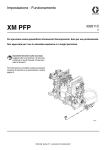
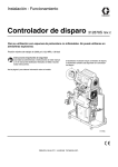
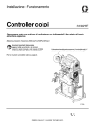
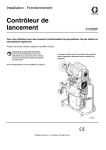
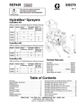
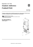
Instructions-Parts
XP Pressure Monitor Kit
3A1331C
ENG
Monitors pressures to provide ratio assurance on XP plural-component sprayers. For
professional use only. Not approved for use in explosive atmosphere locations.
Important Safety Instructions
Read all warnings and instructions in this manual
and the XP sprayer operation manual.
Save these instructions.
Models
262940:
Line Power Pressure Monitor Kit with Light Tower
262942:
Air Turbine Power Pressure Monitor Kit with Light Tower
PROVEN QUALITY. LEADING TECHNOLOGY.
Contents
Overview............................................................ 3
Operating Window ....................................... 3
Component Identification.....................................
262940 Line Power Kit .................................
262942 Air Turbine Kit..................................
User Interface ..............................................
Display Components .............................
4
4
5
6
7
Installation.......................................................... 8
Location ...................................................... 8
Install Air Solenoid ....................................... 8
Install Electronics Box and LCM.................... 9
Install Pressure Transducers ........................ 9
Connect Air Hoses and Cables ..................... 10
Startup............................................................... 10
Shutdown........................................................... 10
Advisories and Alarms ........................................ 11
Clear Alarms................................................ 11
View Current Alarms .................................... 11
View Error Log............................................. 12
Error Codes ................................................. 13
Repair................................................................ 16
Replace LCM Tear Off Sheet ........................ 16
Replace Switch Fuses .................................. 16
2
Replace Filter Element ................................. 16
Replace Alternator or Turbine
Cartridge........................................ 17
Parts.................................................................. 18
Appendix A— User Interface Display ................... 22
Setup Mode Details...................................... 22
Changing Setup Parameters .................. 22
Setup Screen 1 ..................................... 22
Setup Screen 2 ..................................... 23
Setup Screen 3 ..................................... 24
Set Password........................................ 24
Run Mode Details ........................................ 25
Circulation Mode Active ......................... 25
Spray Mode Active ................................ 25
Alarm Active ......................................... 25
Deviation Active .................................... 26
Information Screen....................................... 26
Appendix B - Breakout Module
Connections.......................................... 27
Accessories........................................................ 28
Technical Data ................................................... 29
Graco Standard Warranty.................................... 30
3A1331C
Overview
Operating Window
Below Minimum Spray Pressure
Topics Covered in this Chapter
♦ Operating Window
The purpose of the pressure monitor kit is to
shutdown the sprayer if abnormal pressure conditions
are detected to prevent spraying material that is not
mixed on ratio.
Two pressure transducers are added to read the A
and B fluid pressures in the outlet manifold and send
the readings back to the Local Control Module (LCM).
The control watches the difference between the A and
B pressures. The control will alarm if the pressures
split because of a plug, leak, or running out of fluid.
When an alarm indicates that the sprayer may be
off ratio, the air solenoid shuts off the air supply to
the proportioner motor. The light tower will indicate
an alarm has occurred, and the alarm code will
be on the LCM display. For more information see
Advisories and Alarms, page 11.
The following alarms can occur:
• Differential Pressure (B>A)
The air motor is allowed to automatically operate in
Circulation Mode with a yellow light anytime the fluid
pressures are below the minimum spray pressure.
This allows for loading the system and circulating the
fluids without alarms or shutdowns.
Above Minimum Spray Pressure
When the control sees the fluid pressures above the
minimum spray pressure for 3–30 seconds, and the
pressures are balanced within the pre-set limits, it
will automatically start the monitor mode, and the
green light on the light tower will change to solid
on. If the control does not see balanced pressures
within 30 seconds of going above the minimum spray
pressure, it will alarm and shut off the air motor. The
default minimum spray pressure is 2000 psi (14 MPa,
138 bar). Enter Setup Mode to change the minimum
spray pressure as necessary.
Maximum Spray Pressure
The control will alarm and shutdown if it sees either A
or B above the maximum working pressure of 7250
psi (50 MPa, 500 bar). Enter Setup Mode to reduce
the maximum allowable pressure set point.
• Differential Pressure (A>B)
• Pressure A High
• Pressure B High
• Air Solenoid Disconnected
• Pressure A Disconnected
• Pressure B Disconnected
3A1331C
3
Component Identification
Topics Covered in this Chapter
♦ 262940 Line Power Kit
♦ 262942 Air Turbine Kit
♦ User Interface
262940 Line Power Kit
SC
SB
SA
SF
SL
D
A
SE
SD
F
SH
E
C
B
G
SJ
SG
Figure 1
Table .2 System Component Identification Table
Table .1 Cable Identification Table
Ref.
System Component
Ref.
Cable
Identification Label
SA
XP Motor Air Controls (reference)
A
Power Supply
CAN
SB
Local Control Module (LCM)
B
A Pressure
Transducer
6–Blue
SC
Power Entry Fuses and Switch
C
B Pressure
Transducer
7–Red
SD
Motor Air Solenoid Valve, 24 Volt
SE
Power Supply, 24 Volt
D
LCM Cable
1–Blue
SF
Light Tower, 24 Volt
E
Solenoid Extension
Cable
3–Red
SG
XP Air Inlet Assembly (reference)
SH
Breakout Module
F
Solenoid Cable
3–Red
SJ
XP Fluid Manifold (reference)
G
Light Tower
4–Green
SL
Motor Air Hose
4
3A1331C
262942 Air Turbine Kit
SK
SN
SB
SA
SF
H
SL
D
SD
A
F
H
J
SM
SH
C
E
B
G
SG
Figure 2
SJ
Table .4 System Component Identification Table
Table .3 Cable Identification Table
Ref.
System Component
Ref.
Cable
Identification Label
SA
XP Motor Air Controls (reference)
A
Power Supply
CAN
SB
Local Control Module (LCM)
B
A Pressure
Transducer
6–Blue
SD
Motor Air Solenoid Valve, 12 Volt
C
B Pressure
Transducer
7–Red
SF
Light Tower, 12 Volt
SG
XP Air Inlet Assembly (reference)
D
LCM Cable
1–Blue
SH
Breakout Module
E
Solenoid Extension
Cable
3–Red
SJ
XP Fluid Manifold (reference)
SK
Turbine Air Regulator
F
Solenoid Cable
3–Red
SL
Motor Air Hose
G
Light Tower
4–Green
SM
Air Powered Alternator, 12 Volt
H
Air Tubing
—
SN
Alternator Power Shutoff Valve
J
Air Exhaust
—
3A1331C
5
User Interface
Table .5 LCM Button Functions
Button
Function
Mode
Select between Run and Setup
Modes.
Spray
Start and stop the air motor. The
motor will stay on indefinitely if
pressures are below minimum
spray pressure. Monitor mode
will start within 30 seconds if the
pressures are above the minimum
spray pressure and no errors exist.
All errors are ignored for up to the
first 30 seconds. Default is 2000
psi (138 MPa, 138 bar)
Arrows
Up/Down
Navigate up or down within a
screen or to a new screen.
Soft Keys
Soft keys activate the mode or
action represented by the icon next
to each soft key.
Figure 3
NOTICE
To prevent damage to soft key buttons, do not
press the buttons with sharp objects such as pens,
plastic cards, or fingernails.
See Table 2 for soft key icons and
actions.
Top Soft Key: Edit data, accept
edited data, or move right within a
number field.
Bottom Soft Key: Enter a screen,
exit a screen, or cancel edited data.
6
3A1331C
Display Components
The following tables identify components shown on
the spray mode active, circulation mode active, alarm
active, and deviation active run screens. For more
information see Run Mode Details, page 25.
Table .6 Display Components
Icon
Function
Actual spray pressures
Differential pressure alarm
bar graph
Selected pressure units.
Indicates that you are in
spray mode.
Indicates that you are in
circulation mode.
Spray Mode Active Screen
Figure 4
Indicates that there is an
active alarm.
Indicates that there is an
active deviation.
Circulation Mode Active Screen
Figure 5
Table .7 Display Soft Key Icons
Icon
Function
Enter Screen
In screens that have editable fields,
press to access the fields and
make changes.
Exit Screen
In screens that have editable fields,
press to exit edit mode.
Enter
In screens that have editable fields,
press to make data selections or
to enter changes.
Right
In screens that have editable fields,
press to move to the right while in
a field.
Cancel
Cancel a selection or edited data.
Returns to the original data.
Clear Error
Log
Clear entire error log..
Alarm Active Screen
Figure 6
Deviation Active Screen
Figure 7
3A1331C
7
Installation
Topics Covered in this Chapter
♦
♦
♦
♦
♦
Location
Install Air Solenoid
Install Electronics Box and LCM
Install Pressure Transducers
Connect Air Hoses and Cables
Install Air Solenoid
1. Disconnect the upper swivel and remove the
motor air line from the lower air manifold.
Note
On early XP sprayers, to remove the
existing air hose, it may be necessary to
remove the air filter assembly from the
XP and put it in a vice. New models XP
sprayers have an additional hose union.
2. For the turbine powered kit 262942, remove a
plug from the air manifold and install the 5/16 in.
x 4 ft (1.2 m) air hose.
Shutdown the XP Sprayer before installing your
pressure monitor kit. Follow the Shutdown and
Pressure Relief Procedure in the XP Sprayer
operation manual. All electrical wiring must be
done by a qualified electrician and comply with all
local codes and regulations.
The procedures in this section are specific to each
component of the pressure monitor kit. For sprayer
installation instructions, refer to the XP70 Sprayer
Operation manual.
Location
Figure 8
These pressure monitoring kits are not approved
for use in hazardous atmosphere locations.
Installing this kit on a XP Sprayer that is EX
approved, voids the approval. The EX mark should
be removed from the machine ID plate when this
kit is installed.
3. Connect the air solenoid valve and new motor
air hose to the air inlet assembly. Ensure that
the air solenoid valve cable faces the back of
the machine.
NOTICE
Do not store a XP Sprayer with a pressure monitor
kit outside in the rain. Use protective bag 16J717
to prevent damage to the electronic components,
used with the pressure monitor kit, when stored
outside.
8
3A1331C
Install Electronics Box and LCM
Early XP carts have two mounting holes and new XP
carts have three mounting holes. Complete steps 1
and 2 to drill a third mounting hole for the pressure
monitor kit. Complete step 2 if you have a new XP
cart.
1. Early XP carts with two mounting holes
a. Use two screws (61) and two nuts (62) to
mount the electronics box to the top of the
cart.
b. Use a marker to mark the bracket’s third
mounting hole.
c.
Loosen the nuts (62) below the cart shelf and
remove the screws (61), and box bracket.
Center punch and drill a 5/16 in. hole in the
top of the cart.
2. New XP carts with three mounting holes.
a. Use three screws (61) and three nuts (62) to
mount the box bracket to the cart.
b. For power supply kits, install the appropriate
power supply cord(s). US, European, and
Australia/Asia cord adapters are supplied.
See Technical Data, page 29.
Early XP Cart Installation
Figure 9
Install Pressure Transducers
1. Remove plugs from the circulation manifold.
Note
Keep plugs if you will ever remove the
pressure monitor kit.
2. Connect pressure transducer (4), with blue
#6 label, with black o-ring (13) to the A side
of the circulation manifold. Connect pressure
transducer (4), with red #7 label, with black o-ring
(13) to the B side of the circulation manifold.
Tighten to 40–50 ft-lb (54–67 N•m) before
applying fluid pressure.
3A1331C
Pressure Transducers
Figure 10
9
Connect Air Hoses and Cables
Reference 262940 Line Power Kit, page 4 and
262942 Air Turbine Kit, page 5 for air hose and
cable connections.
Use tie wraps provided to secure hose and cables.
For turbine kit 262942, route exhaust hose down cart
leg and secure.
• 262942: Secure solenoid cable (F) to air hoses
with tie wrap. Route exhaust hose (J) down the
inside of the cart leg and secure with tie wrap.
• 262940: Route solenoid cable (F) behind the air
hose and secure with tie wrap.
Startup
1. Refer to your XP Sprayer Operation manual for
sprayer startup instructions.
Note
The pressure monitor kit modifies XP
sprayers. However, the operation
procedures from the XP sprayer
Operation manual still apply.
2. Turn on power.
a. For 262940: Turn on power switch (9)
located on the electronics box.
b. For 262942: Open ball valve (22) located
outside of the electronics box.
3. Wait for the power up screen to complete. The
Circulation Mode screen will display. The light
tower will briefly flash green, yellow, and red to
verify the lights before staying on yellow. Wait for
the run screen to appear.
4. Set system parameters before spraying.
These can be changed as necessary.
Press
10
more information and default settings, see
Setup Mode Details, page 22.
5. In Circulation Mode, all alarms are disabled
except for the air solenoid detection, pressure
sensor failure, and high pressure alarms.
Note
In Manual Bypass Mode you can still
spray when one pressure transducer
fails, but the control no longer monitors
the pressures and will not shut off the
sprayer. This is for emergency only.
a. To enter Manual Bypass Mode, set the
minimum spray pressure equal to the
maximum spray pressure on setup screen
2. In Manual Bypass Mode, the system can
never get into Spray Mode. The event code
EVC1 is displayed on the information screen
and logged in the error log. The yellow light
is always on and all alarms are ignored.
b. To exit Manual Bypass Mode, set the
mimimum spray pressure and maximum
spray pressure to different spray pressures.
Event code EVC0 will log in the error log
when Bypass Mode is disabled.
6. Press
to start the air motor. The red LED
will turn on and the motor will start. Only spray
when the green light on the light tower is on. For
more information about the LCM run screens,
see Run Mode Details, page 25.
Shutdown
1. Press
. The red LED will turn off and the
motor will stop.
2. Turn off the power switch or ball valve on the
outside of the electronics box.
to enter Setup Mode. For
3A1331C
Advisories and Alarms
Topics Covered in this Chapter
♦
♦
♦
♦
Clear Alarms
View Current Alarms
View Error Log
Error Codes
The following table explains the error type that is
associated with the particular light tower LED.
Light Tower
LED
Description
Green Solid
System is powered up and
monitoring pressure.
Yellow Solid
In Circulation Mode or Manual
Bypass Mode
There are three types of errors that can occur. Errors
are indicated by the light tower as well as on the
display.
Yellow
Flashing
A deviation exists
An alarm exists and the system
Red Solid
Alarms indicated by
, require immediate
attention; therefore, the control disables the air motor
and the Information screen automatically displays.
Deviations, indicated by
not immediately.
, require attention, but
Advisories, indicated by
, do not require
attention. Therefore, if a deviation or advisory occur,
the system continues running and
or
displays next to the operation mode field.
shuts down
Clear Alarms
Fore more information about the alarms, see
Information Screen, page 26.
To clear an error:
1. Press
to clear the alarm.
2. Press
to restart the air motor.
View Current Alarms
From the Run screen, press
to navigate
to the Information screen. The Information screen
displays current alarms or advisories.
Figure 11
3A1331C
11
View Error Log
Setup Screen 3 is the error log screen. It displays the
most recent error on the top of the list with the past
three errors below it. This screen displays a list of
advisory or alarm error codes and the time the error
occurred since the kit was powered on.
12
3A1331C
Error Codes
Code
Icon
Code Name
Light Tower
Code
Cause
Solution
Alarms
J4AX
J4BX
P6AX
3A1331C
Differential Pressure
(A>B)
Differential Pressure
(B>A)
Pressure A
Disconnected
Red Solid
Red Solid
Red Solid
Ran out of B side
material.
Refill hopper or
change drum.
Cavitating B side
pump.
Warm material or add
feed pressure.
B material leaking.
Follow pump
troubleshooting in
XP70 Sprayer manual.
No mix manifold B
side restriction.
Add restriction to B
side on mix manifold
to balance pressures.
A side hose is too
small.
Change to larger hose
size.
Improper
configuration.
Adjust setpoints on
setup screens. See
Setup Mode Details,
page 22.
Ran out of A side
material.
Refill hopper or
change drum.
Cavitating A side
pump.
Warm material or add
feed pressure.
A material leaking.
Follow pump
troubleshooting in
XP70 Sprayer manual.
Too much restriction
on mix manifold B side
restriction.
Reduce restriction to B
side on mix manifold.
* Bside hose is too
small.
Change to larger
diameter hose size.
* No B side offset in
control setup.
Adjust B side offset
in setup screens if
B normally runs at a
higher pressure than
A. See Setup Mode
Details, page 22.
Improper
configuration.
Adjust setpoints on
setup screens. See
Setup Mode Details,
page 22.
Broken cable.
Replace transducer.
Disconnected cable.
Connect cable.
13
Code
Icon
Code Name
Light Tower
Code
Cause
Solution
Alarms
P6BX
WJPX
Pressure B
Disconnected
Red Solid
Air Solenoid
Disconnected
Red Solid
Broken cable.
Replace transducer.
Disconnected cable.
Connect cable.
Broken cable.
Replace cable.
Disconnected cable.
Connect cable.
Damaged solenoid.
Replace solenoid.
P4AX
Pressure A High
Red Solid
A pressure exceeded
maximum working
pressure set point.
Reduce air pressure
to motor or adjust
setpoint.
P4BX
Pressure B High
Red Solid
A pressure exceeded
maximum working
pressure set point.
Reduce air pressure
to motor or adjust
setpoint.
Open down stream
valve.
Blockage in B line
downstream.
Reduce downstream
restriction.
Clean mix manifold.
* Remote mix manifold applications only.
14
3A1331C
Code
Icon
Code Name
Light Tower
Code
Cause
Solution
Deviations
J3AX
Differential Pressure
(A>B)
J3BX
Differential Pressure
(B>A)
Yellow
Flashing
Yellow
Flashing
Ran out of B side
material.
Refill hopper or
change drum.
Cavitating B side
pump.
Warm material or add
feed pressure.
B material leaking.
Follow pump
troubleshooting in
XP70 Sprayer manual.
No mix manifold B
side restriction.
Add restriction to B
side on mix manifold
to balance pressures.
A side hose is too
small.
Change to larger hose
size.
Ran out of A side
material.
Refill hopper or
change drum.
Cavitating A side
pump.
Warm material or add
feed pressure.
A material leaking.
Follow pump
troubleshooting in
XP70 Sprayer manual.
Too much restriction
on mix manifold B side
restriction.
Reduce restriction
to GB side on mix
manifold.
* B side hose too
small.
Change to larger hose
size.
* No B side offset in
control setup.
Add B side offset in
setup screen.
Events and Advisories
EERX
Under Minimum Spray
Pressure, Circulation,
Loading
Yellow
EVC0
Manual Bypass Mode
Enabled and Logged.
Minimum Pressure =
Maximum Pressure
Yellow
—
Manual Bypass Mode
Disabled and Logged
—
—
Control Power Up
Timer set to zero
in Log
—
EVC1
ELCX
Under minimum spray
pressure.
Normal for circulation
mode.
Manual Bypass Mode
Reset minimum
spray pressure and
maximum spray
pressure in Setup
Mode.
Event log only
—
Event log only
—
* Remote mix manifold applications only.
3A1331C
15
Repair
Topics Covered in this Chapter
♦ Replace LCM Tear Off Sheet
♦ Replace Switch Fuses
♦ Replace Filter Element
♦ Replace Alternator or Turbine Cartridge
For system specific repair procedures, refer to your
XP Sprayer instructions-parts manual.
Replace LCM Tear Off Sheet
The LCM is supplied with 10 protective tear off sheets
that prevent spray material from covering the LCM
display.
1. Peel away the dirty protective sheet.
2. Install a new protective sheet (68) on the LCM
display.
Figure 13
Replace Filter Element
There is a 5 micron air filter used with the regulator
on the alternator power kit 262942. Check the filter
monthly and replace element as needed.
1. Close main air shutoff valve on air supply line
and on unit. Depressurize air line.
2. Remove box cover (30).
3. Press silver tab in, twist bowl to the left, and pull
down off of the regulator.
4. Remove and replace element.
5. Screw filter bowl on securely until the tab clicks.
Figure 12
Replace Switch Fuses
For 262940 only.
1. Remove power inlet cord (55 or 57).
2. Pry off small plastic cover above cord inlet.
3. Pull fuses (63) out of power switch. Replace and
reassemble.
16
Figure 14
3A1331C
Replace Alternator or Turbine
Cartridge
For 262942 only.
Turbine alternator cartridge 257147 (34e) can be
replaced in alternator 262579 (34).
1. Turn off air supply.
2. Close ball valve (22).
3. Remove box cover (30).
10. Reassemble.
Note
• Lightly lubricate turbine o-ring before
installing turbine in housing.
• Align ribbon connector and firmly press
the cartridge into the top housing.
• Connect turbine to 3–pin connector on
main circuit board.
• Torque housing screws evenly to 18
in.-lbs (2 N•m).
• Reassemble into control box (1).
Z
Figure 15
4. Disconnect the alternator power supply cable (A)
from the LCM (21). Disconnect ground wire (Z).
5. Disconnect air tube (40) from the alternator (34).
A
Figure 16
AB
34d
6. Remove two screws (15) to remove alternator
from the box (1).
7. Remove four screws (34d) to separate alternator
housings.
34e
8. Disconnect turbine cartridge ribbon connector
(34e) from board (AB).
34a
9. Replace gasket (34a) if damaged. Place between
housings before securing with screws (34d).
Z
Figure 17
3A1331C
17
Parts
262940 Line Power Pressure Monitor Kit
Apply sealant to all non-swiveling pipe threads.
* Already included on new XP model sprayers.
18
3A1331C
Ref. Part
Description
Qty.
Ref. Part
Description
Qty.
1
262457
BOX, weldment assembly
1
29
15T859
1
2
—
BRACKET, top mount
1
CABLE, assembly, DB25,
10 ft (3 m)
30
—
COVER, box
1
31
102063
WASHER, lock, ext
1
32
108865
SCREW, cap, button hd
1
33
121806
CABLE, solenoid
1
43
122030
CABLE, GCA, M12-5P
1
47
16H323
GROMMET, one slit
1
53
120206
MUFFLER, sintered, dia
1/8
1
55
116281
CORD SET, IEC320(M-F),
6 ft (1.8 m)
1
56
195551
RETAINER, plug, adapter
1
57
245202
CORD, SET, USA, 10 ft (3
m), 13 AMP, 120V
1
58
242001
CORD SET, adapter,
Europe; 8 in. (20 mm)
1
59
242005
CORD SET, adapter,
Australia-Asia; 8 in. (20
mm)
1
61
113796
SCREW, flanged, hex hd
3
62
115942
NUT, hex, flange head
3
3
15M293 POWER SUPPLY, 24VDC,
2.5A, 60W, gnd wire
1
4
15M669 SENSOR, pressure, fluid
outlet
2
5
15X472
LIGHT TOWER, m12
1
6
—
BRACKET, mounting
1
7
258999
MODULE, LCM, breakout
1
8
157785
SWIVEL
2
9
121254
SWITCH, power, 120V
1
11
102410
SCREW, cap, sch
4
12
100016
WASHER, lock
1
13
121399
O-RING 012, solvent
resistant
2
14▲ 189930
LABEL, caution
1
15
104371
SCREW,cap sch 10X.375
4
16
104472
SCREW, cap; 10–32 x 1.5
4
17
110755
18
—
WASHER, plain
1
63
121261
FUSE, 250V / 1.2A
2
SCREW, countersunk,
6-32 x .38
2
65
114606
PLUG, hole
1
67
113783
SCREW, 1/4–20, pn hd
4
68
16H378
SHIELD, membrane, LCM
(pack of 10)
1
69
114225
TRIM, edge protection; 0.6
ft (0.18 m)
1
70
16J685
LABEL, error codes
1
20
110047
HOSE, coupled, 18 in.
(457.2 mm)
1
21
24H286
MODULE, LCM; includes
21a and instructions
1
TOKEN, PM software; not
shown
1
MODULE, LCM
1
21a 16G728
—
21b◆
▲ Replacement Danger and Warning labels, tags,
25
121253
KNOB, display adjustment
1
and cards are available at no cost.
26
119992
NIPPLE, 3/4 x 3/4 npt
1
◆ Base electronic components do not have Pressure
27
111530
MUFFLER
1
28
16G901
VALVE, 24VDC, internal
pilot, 3/4
1
3A1331C
Monitor specific software installed. Therefore, use
software upgrade token (21a) to install software
before use.
19
262942 Air Turbine Pressure Monitor
Kit
Apply sealant to all non-swiveling pipe threads.
* Already included on new XP model sprayers.
20
3A1331C
Ref. Part
Description
Qty.
Ref. Part
Description
Qty.
1
262457
BOX, assembly
1
33
121806
CABLE, solenoid
1
2
—
BRACKET, top mount
1
34
262579
MODULE, alternator, M12,
non-IS
1
34a 193154
GASKET, alternator
1
34e 257147
CARTRIDGE, alternator
1
35
FILTER REGULATOR, 3/8
npt (auto drain)
1
4
15M669 SENSOR, pressure, fluid
outlet
2
5
16H600
LIGHT, tower, M12,
12VDC
1
6
—
BRACKET, mounting
1
7
258999
MODULE, LCM, breakout
1
35a 11228
ELEMENT, filter, 5 micron
1
8
157785
FITTING, swivel; 3/4 mxf
2
36
108190
GAUGE, pressure, air
1
12
100016
WASHER, lock; 1/4
1
37
121858
1
13
121399
O-RING 012, solvent
resistant
2
ELBOW ,3/8 nptm x 1/4
nptm
38
125385
VALVE, safety, regulator
1
14▲ 189930
LABEL, caution
1
39
114153
ELBOW, male, swivel
1
15
104371
SCREW, cap sch 10 x
0.375
9
40
054175
TUBE, nylon, rd; 1/4, 0.6 ft
(0.18 m)
1
16
104472
SCREW, cap; 10–32 x 1.5
4
41
C12508
1
17
110755
WASHER, plain
1
TUBING, nylon, round;
3/8, 4 ft (1.2 m)
18
108026
SCREW, cap, hex, button
hd; 6–32 x 3/8
2
42
248208
HOSE, coupled ,6 ft (1.8
m), 1/4 npsm, 5/16
1
20
110047
HOSE, coupled, 3/4 npt x
18 in. (457.2 mm)
1
43
122030
CABLE, M12-5P m x f; 20
in. (508 mm)
1
21
24H286
MODULE, LCM; includes
21a and instructions
1
47
16H323
GROMMET, one slit
1
53
120206
1
TOKEN, PM software; not
shown
1
MUFFLER, sintered, dia
1/8
61
113796
3
MODULE, LCM
1
SCREW, flanged, hex hd;
1/4–20
62
115942
NUT, hex, flange head;
1/4–20
3
66
158962
ELBOW, st pipe, rdcg
1
67
113783
SCREW, 1/4–20, pn hd
4
68
16H378
SHIELD, membrane, LCM
(pack of 10)
1
69
114225
TRIM, edge protection; 0.6
ft (0.18 m)
1
70
16J685
LABEL, error codes
1
21a 16G728
—
21b◆
22
15B565
VALVE, ball
1
23
114314
WASHER, plain
2
24▲ 172953
LABEL, ground
1
25
121253
KNOB, display adjustment
1
26
119992
NIPPLE, 3/4 x 3/4 npt
1
27
111530
MUFFLER
1
28
16H550
VALVE, 12VDC, internal
pilot, 3/4
1
CABLE, assembly, DB25,
10 ft (3 m)
1
COVER, box
1
29
15T859
30
—
31
C38163
WASHER, lock, ext. tooth
1
32
103833
SCREW, machined, crbh
1
3A1331C
119644
▲ Replacement Danger and Warning labels, tags,
and cards are available at no cost.
◆ Base electronic components do not have Pressure
Monitor specific software installed. Therefore, use
software upgrade token (21a) to install software
before use.
21
Appendix A— User Interface Display
Topics Covered in this Chapter
♦ Setup Mode Details
♦ Run Mode Details
♦ Information Screen
Setup Mode Details
Setup Screen 1
Setup mode screens enable user to view or modify
system configuration data. User can set:
Setup screen 1 enables users to set units of
measurement that will display on other screens,
differential warning and differential alarm.
Additionally, this screen displays the software
number and version. Refer to the following table for
more information.
• Units of pressure
• Differential pressure warning value
• Differential pressure alarm value
• High pressure limit value
• Minimum spray pressure value
• Normal B pressure offset value
Changing Setup Parameters
1. Navigate to a Setup screen by pressing . Then
use
to select a screen.
2. Press
to access fields and make changes.
3. Press
to navigate to the field that you want
to change. Press
to edit data.
Icon
Function
Warning Pressure
Adjust the differential pressure
deviation setpoint. The yellow light
on the light tower will be flashing.
Default: 400 psi
Range: 0–2000 psi
Alarm Pressure
4. Press
to select digits.
5. Press
to accept the new values or press
to cancel.
6. Press
to exit edit mode.
Adjust the differential pressure alarm
setpoint. The red light on the light
tower will be solid on.
This is the main setting that
determines how far apart your A and
B pressures can be before shutting
down the machine. If the machine
shuts down too easily, increase this
to a higher setpoint.
Default: 600 psi
Range: 0–2000 psi
22
3A1331C
Setup Screen 2
Setup screen 2 enables users to set the high spray
pressure alarm limit value, minimum spray pressure
value and B pressure offset. Refer to the following
table for more information.
Icon
Function
B Side Pressure Offset
Default: 0 psi
Range: -999 to 999 psi
Only used for remote mix manifold
applications where there is a normal
difference in pressure between A and
B.
Icon
Function
High Pressure Limit
Remote mix manifold applications
should first be balanced with proper
hose sizing and adjusting the mix
manifold B restrictor. See manual
3A0590.
Default: 7250 psi (14 MPa, 138 bar)
Use if your differential alarm bar
graph on the Spray screen is off
to one side under normal spray
conditions.
Range: 0-7250 psi (50 MPA, 500
See B Side Pressure Offset Example.
Adjust the high pressure limit.
bar) maximum
Minimum Spray Pressure Limit
B Side Pressure Offset Example
Adjust the lower spray pressure limit.
In normal spray conditions, the B pressure is 300
psi above the A pressure. The bar graph is offset
to one side.
Default: 2000 psi (14 MPa, 138 bar)
Range: 0-7250 psi (50 MPA, 500
bar) maximum
Password
The setup screens can be protected
by a password to restrict their
accessibility. To set the password,
see Set Password, page 24.
Range: 0-9999
Enter a B offset pressure of +300 psi. Now the bar
graph Is centered.
The differential pressure alarm now sees no
differential when the B pressure is 300 psi higher
than the A pressure. If the B pressure was normally
300 psi lower than the A pressure, you would enter
—300 psi to balance the offset.
3A1331C
23
Setup Screen 3
Setup screen 3 enables users to scroll through all
errors and clear the entire error log. The error log will
display the most recent error on the top of the list .
Refer to the following table for more information.
Set Password
Note
When the password is “0000,” the setup
screens can be accessed without entering
a password.
1. Navigate to setup screen 2.
Icon
Function
Error Number
The first column lists the error
number. Once the system has
more than the maximum errors
allowed, then the oldest error will be
over-written.
Maximum: 99
2. Press
to access fields to make changes.
3. Press
to navigate to the password field.
to edit data.
Press
Error Code
and
to increment or
4. Press
decrement to the desired digits of the password.
The second column lists the errors
codes. See Error Codes, page 13.
5. Press
Maximum: 99
to cancel.
Time
The third column shows the time that
the error occurred since the unit was
last powered on. The time will always
start at 0:00 when the system is
powered up. This time will be logged
as code ELCX.
Format: Hours : Minutes
to accept the password or press
6. Press
to exit edit mode.
Note
The password screen is shown when
the setup screens are accessed and the
password function has been enabled by
changing the 0000 password.
Maximum: 999 : 59
Reset
Press the Reset icon to clear the
entire error log.
Figure 18
If you set and forget the password, please
contact Graco Technical Assistance for a default
password.
24
3A1331C
Run Mode Details
Spray Mode Active
There are four Run Screens: Circulation Mode
Active, Spray Mode Active, Alarm Active, and
Deviation Active.
This is the run screen that appears during spray
mode. A and B pressure are shown. The bar across
the bottom indicates the magnitude of the differential
pressure with respect to the alarm setpoint.
Circulation Mode Active
When the pressure first gets above the lower spray
pressure limit, the user has 30 seconds to balance
the system differential pressure so it is less that the
differential pressure deviation and alarm limits. Then
the system will automatically go into Spray mode and
start monitoring all alarms and deviations.
This is the run screen that appears after the power up
screen. A and B pressure are shown. The bar across
the bottom indicates the magnitude of the differential
pressure with respect to the alarm setpoint. In
Circulation Mode, all alarms are disabled except for
the Air Solenoid Detection High Pressure A, and High
Pressure B alarms
If the user needs to spray with one of the above errors
active, set the Lower Spray Pressure Limit equal
to the High Pressure Alarm Limit to enter Manual
Bypass Mode. Only use Manual Bypass Mode for
emergency operation. The control no longer monitors
the pressures and will not shut off the sprayer.
Icon
Icon
Indicates that you are in spray
mode, at least one of the pumps has
pressure greater than the lower spray
pressure limit, and the differential
pressure is less that the differential
pressure deviation setpoint.
The green light on the light tower will
be solid on.
System Status
Indicates that you are in Circulation
Mode and the fluid pressure is below
the Lower Spray Pressure Limit.
All alarms are disabled except for Air
Solenoid Detection, High Pressure
A, and High Pressure B alarms. The
yellow light on the light tower will be
solid on.
System Status
Alarm Active
This is the run screen that appears during an active
alarm. A and B pressure are shown. The bar across
the bottom indicates the magnitude of the differential
pressure with respect to the alarm setpoint. Refer to
the following table for more information.
This screen will also be used when in
Manual Bypass Mode.
Note
All alarms and deviations
are ignored in Bypass Mode.
You will be allowed to spray
bad material. The yellow
light will be solid on.
Icon
System Status
Indicates that there is an active
alarm.
The red light on the light tower will be
solid on and the system is disabled.
3A1331C
25
Deviation Active
Information Screen
This is the run screen that appears during an
active deviation. A and B pressure are shown.
The bar across the bottom indicates the magnitude
of the differential pressure with respect to the
alarm setpoint.Refer to the following table for more
information.
The information screen is only available when an
alarm, deviation, or advisory is active. It shows
the active alarm code and the A and B pressure
conditions at the time of the alarm, if applicable.
If the alarm condition occurs while on the run screen
the information screen is automatically generated.
The red light on the light tower will be solid on. Refer
to the following table for more information
Icon
System Status
Indicates that there is an active
deviation.
The yellow light on the light tower will
be flashing.
The air to the motor is on. Once the
deviation condition no longer exists
it automatically generates the Spray
Mode Active Run Screen
Icon
System Status
Indicates that there is an active
alarm.
The red light on the light tower will be
solid on and the system is disabled.
Indicates that there is an active
deviation.
The yellow light on the light tower will
be flashing.
Indicates that there is an active
advisory.
The yellow light on the light tower will
be solid on.
Active Alarm Code
See Error Codes, page 13.
26
3A1331C
Appendix B - Breakout Module Connections
The following provides descriptions and pins of all
connectors used on the breakout module. These can
be used if the components are being wired directly
to the breakout module.
LCM Power
Cable 1 — Blue
Pin Description
Pin Number
M12
Connector, 5
pin, Female, A
code
Shield
1
Phoenix
Contact Part
Number
1694224
Power (12 V or
24 V)
2
Ground
3
CAN +
4
CAN -
5
Solenoid Air
Connector 3 —
Red
Pin Description
Pin Number
M12
Connector, 5
pin, Female, A
code
Solenoid Air
Digital Output
4
Phoenix
Contact Part
Number
1542761
Not Used
2
3A1331C
Not Used
1
Digital Output
Ground
3
Not Used
5
Light Tower
Connector 4—
Green
Pin Description
Pin Number
M12
Connector, 5
pin, Female, A
code
Lamp 1 Green
Digital Output
4
Phoenix
Contact Part
Number
1542761
Lamp 2 Yellow
Digital Output
2
Not Used
1
Digital Output
Ground
3
Lamp 3 Red
Digital Output
5
A Pressure
Transducer 6—
Blue
Pin Description
Pin Number
M12
Connector, 5
pin, Female, B
code
Pressure
Differential
Analog Input
+
4
Phoenix
Contact Part
Number
1543650
Pressure
Differential
Analog Input
-
2
Pressure
Power (5 volt)
1
Pressure
Ground
3
Shield Analog
5
27
Accessories
B Pressure
Transducer 7—
Red
Pin Description
Pin Number
M12
Connector, 5
pin, Female, B
code
Pressure
Differential
Analog Input
+
4
Phoenix
Contact Part
Number
1543650
Pressure
Differential
Analog Input
-
2
Pressure
Power (5 volt)
1
16J717, Protective Bag
Pressure
Ground
3
If the pressure monitor kit will be outside, use the
protective bag for weather and over spray protection.
Shield Analog
5
28
16G410, Pressure Transducer Tee Adapter
For using the pressure transducers on systems other
than a XP Sprayer.
303 stainless steel, 7250 psi (50 MPa, 500 bar), 1/4
npt(f) x 3/8 npt (f); 11/16-24 transducer mount on
branch of tee.
3A1331C
Technical Data
Pressure Transducers
Fluid pressure range:
50-7250 psi (3-500 bar)
Power requirements for
model 262940:
Voltage:
90-260 VAC
Frequency:
50-60 Hz
Phase:
1
Amps:
1
Compressed air
requirements for model
262942:
Minimum air supply
pressure
40 psi (2.75 bar)
Maximum air supply
pressure
150 psi (10.3 bar)
Air Consumption
6 scfm
Turbine air pressure
set point (pre-set inside
box)
25 psi (1.72 bar)
Certification:
CE*
* When an Electrostatic Discharge (ESD) is applied
to the display, the screen might clear. Turn the power
supply off and on, or turn the turbine off and on.
3A1331C
29
Graco Standard Warranty
Graco warrants all equipment referenced in this document which is manufactured by Graco and bearing its
name to be free from defects in material and workmanship on the date of sale to the original purchaser for
use. With the exception of any special, extended, or limited warranty published by Graco, Graco will, for a
period of twelve months from the date of sale, repair or replace any part of the equipment determined
by Graco to be defective. This warranty applies only when the equipment is installed, operated and
maintained in accordance with Graco’s written recommendations.
This warranty does not cover, and Graco shall not be liable for general wear and tear, or any malfunction,
damage or wear caused by faulty installation, misapplication, abrasion, corrosion, inadequate or improper
maintenance, negligence, accident, tampering, or substitution of non-Graco component parts. Nor shall
Graco be liable for malfunction, damage or wear caused by the incompatibility of Graco equipment
with structures, accessories, equipment or materials not supplied by Graco, or the improper design,
manufacture, installation, operation or maintenance of structures, accessories, equipment or materials
not supplied by Graco.
This warranty is conditioned upon the prepaid return of the equipment claimed to be defective to an
authorized Graco distributor for verification of the claimed defect. If the claimed defect is verified, Graco
will repair or replace free of charge any defective parts. The equipment will be returned to the original
purchaser transportation prepaid. If inspection of the equipment does not disclose any defect in material
or workmanship, repairs will be made at a reasonable charge, which charges may include the costs of
parts, labor, and transportation.
THIS WARRANTY IS EXCLUSIVE, AND IS IN LIEU OF ANY OTHER WARRANTIES, EXPRESS OR
IMPLIED, INCLUDING BUT NOT LIMITED TO WARRANTY OF MERCHANTABILITY OR WARRANTY
OF FITNESS FOR A PARTICULAR PURPOSE.
Graco’s sole obligation and buyer’s sole remedy for any breach of warranty shall be as set forth above.
The buyer agrees that no other remedy (including, but not limited to, incidental or consequential damages
for lost profits, lost sales, injury to person or property, or any other incidental or consequential loss) shall
be available. Any action for breach of warranty must be brought within two (2) years of the date of sale.
GRACO MAKES NO WARRANTY, AND DISCLAIMS ALL IMPLIED WARRANTIES OF
MERCHANTABILITY AND FITNESS FOR A PARTICULAR PURPOSE, IN CONNECTION WITH
ACCESSORIES, EQUIPMENT, MATERIALS OR COMPONENTS SOLD BUT NOT MANUFACTURED BY
GRACO. These items sold, but not manufactured by Graco (such as electric motors, switches, hose, etc.),
are subject to the warranty, if any, of their manufacturer. Graco will provide purchaser with reasonable
assistance in making any claim for breach of these warranties.
In no event will Graco be liable for indirect, incidental, special or consequential damages resulting from
Graco supplying equipment hereunder, or the furnishing, performance, or use of any products or other
goods sold hereto, whether due to a breach of contract, breach of warranty, the negligence of Graco, or
otherwise.
FOR GRACO CANADA CUSTOMERS
The Parties acknowledge that they have required that the present document, as well as all documents,
notices and legal proceedings entered into, given or instituted pursuant hereto or relating directly or
indirectly hereto, be drawn up in English. Les parties reconnaissent avoir convenu que la rédaction du
présente document sera en Anglais, ainsi que tous documents, avis et procédures judiciaires exécutés,
donnés ou intentés, à la suite de ou en rapport, directement ou indirectement, avec les procédures
concernées.
Graco Information
For the latest information about Graco products, visit www.graco.com.
To place an order, contact your Graco Distributor or call to identify the nearest distributor.
Phone: 612-623-6921 or Toll Free: 1-800-328-0211 Fax: 612-378-3505
All written and visual data contained in this document reflects the latest product information available at the time of publication.
Graco reserves the right to make changes at any time without notice.
Original instructions. This manual contains English, MM 3A1331
Graco Headquarters: Minneapolis
International Offices: Belgium, China, Japan, Korea
GRACO INC. P.O. BOX 1441 MINNEAPOLIS, MN 55440-1441
Copyright 2011, Graco Inc. is registered to ISO 9001
Revised 04/2011