1
Instructions - Parts
SmartWare™ Shot
Dispense Kit
3A0294G
EN
Accurate metered dispensing kit for one component materials. Kits are compatible with
Check-Mate® pumps and Dura-Flo™ pumps; both alone and as part of a supply system. For
professional use only.
Not approved for use in European explosive atmosphere locations.
Important Safety Instructions
Read all warnings and instructions in this manual.
Save these instructions.
Kit 262370 for D200 and D60
For D200 3 inch dual post ram with NXT®2200 and larger air motors
For D60 3 inch dual post ram with NXT2200 and larger air motors
Kit 262371 for D200
For D200 3 inch dual post ram with NXT1800 and smaller air motors
Kit 262372 for D200S
For D200S 6 inch dual post ram with NXT2200 and larger air motors
Kit 262373 for S20
For S20 3 inch single post ram NXT2200 and larger air motors
Kit 262374 for S20
For S20 3 inch single post ram with NXT1800 and smaller air motors
Kit 262375 for pumps
For wall mount or floor stand pump with NXT2200 and larger air
motors
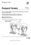
Kit 262370 Shown
Contents
Related Manuals . . . . . . . . . . . . . . . . . . . . . . . . . . . 3
Warnings . . . . . . . . . . . . . . . . . . . . . . . . . . . . . . . . . 4
System Description . . . . . . . . . . . . . . . . . . . . . . . . . 6
Typical Applications . . . . . . . . . . . . . . . . . . . . . . . 6
Compatibility . . . . . . . . . . . . . . . . . . . . . . . . . . . . 6
Critical System Parameters . . . . . . . . . . . . . . . . . 6
Theory of Operation . . . . . . . . . . . . . . . . . . . . . . . . 7
Component Identification . . . . . . . . . . . . . . . . . . . . 8
User Interface . . . . . . . . . . . . . . . . . . . . . . . . . . 10
Grounding . . . . . . . . . . . . . . . . . . . . . . . . . . . . . . . 15
Installation . . . . . . . . . . . . . . . . . . . . . . . . . . . . . . . 16
Location . . . . . . . . . . . . . . . . . . . . . . . . . . . . . . 16
Install Kits 262370 and 262372 . . . . . . . . . . . . . 16
Install Kit 262371 . . . . . . . . . . . . . . . . . . . . . . . 24
Install Kit 262373 . . . . . . . . . . . . . . . . . . . . . . . 30
Install Kit 262374 . . . . . . . . . . . . . . . . . . . . . . . 37
Install Kit 262375 . . . . . . . . . . . . . . . . . . . . . . . 43
Setup . . . . . . . . . . . . . . . . . . . . . . . . . . . . . . . . . . . . 50
Enter Password . . . . . . . . . . . . . . . . . . . . . . . . . 50
Setup Pump . . . . . . . . . . . . . . . . . . . . . . . . . . . 50
Pressure Relief Procedure . . . . . . . . . . . . . . . . . . 51
Prime/Purge . . . . . . . . . . . . . . . . . . . . . . . . . . . . . . 52
Set System Parameters . . . . . . . . . . . . . . . . . . . . . 53
Set Units and Specific Gravity . . . . . . . . . . . . . . 53
Define Shot Size . . . . . . . . . . . . . . . . . . . . . . . . 54
Define Shot Sequence . . . . . . . . . . . . . . . . . . . 55
Set Password . . . . . . . . . . . . . . . . . . . . . . . . . . 56
Select Pump . . . . . . . . . . . . . . . . . . . . . . . . . . . 57
Enable/Disable Pump Functions . . . . . . . . . . . . 57
Enable/Disable Errors . . . . . . . . . . . . . . . . . . . . 58
Set Low/Empty Drum Error . . . . . . . . . . . . . . . . 58
Set Pump Runaway Error . . . . . . . . . . . . . . . . . 59
Set Maintenance Parameters . . . . . . . . . . . . . . 59
Calibrate . . . . . . . . . . . . . . . . . . . . . . . . . . . . . . 60
Set Shot Accuracy Errors . . . . . . . . . . . . . . . . . 61
Operation . . . . . . . . . . . . . . . . . . . . . . . . . . . . . . . . 62
Startup . . . . . . . . . . . . . . . . . . . . . . . . . . . . . . . 62
Change Operation Mode . . . . . . . . . . . . . . . . . . 62
Select a Shot Number . . . . . . . . . . . . . . . . . . . . 64
Select a Shot Sequence . . . . . . . . . . . . . . . . . . 64
Dispense a Shot . . . . . . . . . . . . . . . . . . . . . . . . 65
Pause or Cancel a Shot . . . . . . . . . . . . . . . . . . 65
2
Errors . . . . . . . . . . . . . . . . . . . . . . . . . . . . . . . . . . . 66
Errors with Light Tower . . . . . . . . . . . . . . . . . . . 66
Clear Errors . . . . . . . . . . . . . . . . . . . . . . . . . . . . 66
Error Codes . . . . . . . . . . . . . . . . . . . . . . . . . . . . 67
Shutdown . . . . . . . . . . . . . . . . . . . . . . . . . . . . . . . . 70
Maintenance . . . . . . . . . . . . . . . . . . . . . . . . . . . . . . 71
Preventive Maintenance Schedule . . . . . . . . . . 71
Pump Maintenance . . . . . . . . . . . . . . . . . . . . . . 71
Supply System Maintenance . . . . . . . . . . . . . . . 71
Cleaning Procedure . . . . . . . . . . . . . . . . . . . . . . 71
Upgrade Display Software . . . . . . . . . . . . . . . . . 72
Clean User Interface Display . . . . . . . . . . . . . . . 72
Troubleshooting . . . . . . . . . . . . . . . . . . . . . . . . . . . 73
Repair . . . . . . . . . . . . . . . . . . . . . . . . . . . . . . . . . . . 74
Replace Display . . . . . . . . . . . . . . . . . . . . . . . . . 74
Electrical Schematics . . . . . . . . . . . . . . . . . . . . . . 75
Digital Output Schematic . . . . . . . . . . . . . . . . . . 75
Digital Input Schematic . . . . . . . . . . . . . . . . . . . 76
Parts . . . . . . . . . . . . . . . . . . . . . . . . . . . . . . . . . . . . 77
Kits 262370 and 262372 . . . . . . . . . . . . . . . . . . 77
Kit 262371 . . . . . . . . . . . . . . . . . . . . . . . . . . . . . 80
Kit 262373 . . . . . . . . . . . . . . . . . . . . . . . . . . . . . 83
Kit 262374 . . . . . . . . . . . . . . . . . . . . . . . . . . . . . 86
Kit 262375 . . . . . . . . . . . . . . . . . . . . . . . . . . . . . 89
Appendix A - User Interface Display . . . . . . . . . . 93
Display Overview . . . . . . . . . . . . . . . . . . . . . . . . 93
Display Details . . . . . . . . . . . . . . . . . . . . . . . . . . 93
Setup Mode Details . . . . . . . . . . . . . . . . . . . . . . 94
Run Mode Details . . . . . . . . . . . . . . . . . . . . . . 100
Appendix B - Tips . . . . . . . . . . . . . . . . . . . . . . . . 102
Calibration Procedure . . . . . . . . . . . . . . . . . . . 102
Tips for Better Accuracy . . . . . . . . . . . . . . . . . 102
Appendix C - Breakout Module (258999)
Connections . . . . . . . . . . . . . . . . . . . . . . . . . . 103
Appendix D - Y-Adapter (124273) Connections 105
Accessories . . . . . . . . . . . . . . . . . . . . . . . . . . . . . 106
Dimensions . . . . . . . . . . . . . . . . . . . . . . . . . . . . . . 106
Technical Data . . . . . . . . . . . . . . . . . . . . . . . . . . . 106
Graco Standard Warranty . . . . . . . . . . . . . . . . . . 108
Graco Information . . . . . . . . . . . . . . . . . . . . . . . . 108
3A0294G
Related Manuals
Related Manuals
Manuals are available at www.graco.com.
Component manuals in U.S. English:
Manual
Description
313526
Supply Systems Operation
313527
Supply Systems Repair-Parts
312376
Check-Mate® Pump Packages
Instructions-Parts
312375
Check-Mate® Displacement Pumps
Instructions-Parts
311827
Dura-Flo™ Displacement Pumps
(145cc,180cc, 220cc, 290cc) Instructions-Parts
311825
Dura-Flo™ Displacement Pumps (430cc,
580cc) Instructions-Parts
311828
Dura-Flo™ Pump Packages (145cc,
180cc, 220cc, 290cc) Instructions-Parts
311826
Dura-Flo™ Pump Packages (430cc,
580cc) Instructions-Parts
312796
NXT® Air Motor (Mxxxxx models)
Instructions-Parts
311238
NXT® Air Motor (Nxxxxx models)
Instructions-Parts
3A1161
Foot Switch Kit Instructions-Parts
3A1162
Changeover Solenoid Kits
Instructions-Parts
3A0294G
3
Warnings
Warnings
The following warnings are for the setup, use, grounding, maintenance, and repair of this equipment. The exclamation point symbol alerts you to a general warning and the hazard symbols refer to procedure-specific risks. When
these symbols appear in the body of this manual, refer back to these Warnings. Product-specific hazard symbols and
warnings not covered in this section may appear throughout the body of this manual where applicable.
WARNING
FIRE AND EXPLOSION HAZARD
Flammable fumes, such as solvent and paint fumes, in work area can ignite or explode. To help prevent
fire and explosion:
• Use equipment only in well ventilated area.
• Eliminate all ignition sources; such as pilot lights, cigarettes, portable electric lamps, and plastic drop
cloths (potential static arc).
• Keep work area free of debris, including solvent, rags and gasoline.
• Do not plug or unplug power cords, or turn power or light switches on or off when flammable fumes are
present.
• Ground all equipment in the work area. See Grounding instructions.
• Use only grounded hoses.
• Hold gun firmly to side of grounded pail when triggering into pail.
• If there is static sparking or you feel a shock, stop operation immediately. Do not use equipment until
you identify and correct the problem.
• Keep a working fire extinguisher in the work area.
SKIN INJECTION HAZARD
High-pressure fluid from dispensing device, hose leaks, or ruptured components will pierce skin. This may
look like just a cut, but it is a serious injury that can result in amputation. Get immediate surgical
treatment.
+
• Do not point dispensing device at anyone or at any part of the body.
• Do not put your hand over the fluid outlet.
• Do not stop or deflect leaks with your hand, body, glove, or rag.
• Follow the Pressure Relief Procedure when you stop dispensing and before cleaning, checking, or
servicing equipment.
• Tighten all fluid connections before operating the equipment.
• Check hoses and couplings daily. Replace worn or damaged parts immediately.
4
3A0294G
Warnings
WARNING
EQUIPMENT MISUSE HAZARD
Misuse can cause death or serious injury.
• Do not operate the unit when fatigued or under the influence of drugs or alcohol.
• Do not exceed the maximum working pressure or temperature rating of the lowest rated system
component. See Technical Data in all equipment manuals.
• Use fluids and solvents that are compatible with equipment wetted parts. See Technical Data in all
equipment manuals. Read fluid and solvent manufacturer’s warnings. For complete information about
your material, request MSDS from distributor or retailer.
• Do not leave the work area while equipment is energized or under pressure. Turn off all equipment and
follow the Pressure Relief Procedure when equipment is not in use.
• Check equipment daily. Repair or replace worn or damaged parts immediately with genuine
manufacturer’s replacement parts only.
• Do not alter or modify equipment.
• Use equipment only for its intended purpose. Call your distributor for information.
• Route hoses and cables away from traffic areas, sharp edges, moving parts, and hot surfaces.
• Do not kink or over bend hoses or use hoses to pull equipment.
• Keep children and animals away from work area.
• Comply with all applicable safety regulations.
MOVING PARTS HAZARD
Moving parts can pinch, cut or amputate fingers and other body parts.
• Keep clear of moving parts.
• Do not operate equipment with protective guards or covers removed.
• Pressurized equipment can start without warning. Before checking, moving, or servicing equipment,
follow the Pressure Relief Procedure and disconnect all power sources.
TOXIC FLUID OR FUMES HAZARD
Toxic fluids or fumes can cause serious injury or death if splashed in the eyes or on skin, inhaled, or
swallowed.
• Read MSDS’s to know the specific hazards of the fluids you are using.
• Store hazardous fluid in approved containers, and dispose of it according to applicable guidelines.
PERSONAL PROTECTIVE EQUIPMENT
You must wear appropriate protective equipment when operating, servicing, or when in the operating area
of the equipment to help protect you from serious injury, including eye injury, hearing loss, inhalation of
toxic fumes, and burns. This equipment includes but is not limited to:
• Protective eyewear, and hearing protection.
• Respirators, protective clothing, and gloves as recommended by the fluid and solvent manufacturer
3A0294G
5
System Description
System Description
SmartWare shot dispense kits contain everything
needed to convert a supply system or a pump system
into a dosing system. The kits enable you to dose a preset amount of single-component material without using
flowmeters or gear meters in the fluid stream. Instead, a
sensor tracks the pump position so that the pump acts
like a flowmeter. The amount dispensed is based on the
pump size.
Typical Applications
•
Cartridge fill
•
Potting
•
Encapsulating
•
Mold making
•
Batching or kitting
Compatibility
SmartWare shot dispense kits are compatible with J
series NXT2200 and larger air motors, and D series
NXT1800 and smaller air motors.
Critical System Parameters
If any of the following parameters are below the recommended value, see Appendix B - Tips, page 102, for
tips for better accuracy.
Percentage (shot size/pump size) -
< 20%
Percentage (overshoot/shot size) (function of valve time and pump speed)
> 10%
< 3%
Air motor pressure (PSI) -
< 50
> 80
Pump Speed (CPM) -
> 40
6
> 100%
< 10
3A0294G
Theory of Operation
Theory of Operation
SmartWare shot dispense kits do not use flowmeters in
the material path to measure the volume pumped.
Instead the kit measures the volume pumped by using
the following calculation. See FIG. 1 for a graphical representation.
Just like a car does not stop the instant you push on the
brake, the SmartWare kit pump does not stop pumping
the instant it receives a stop signal. Therefore, during
the time it takes for the dispense valve to physically
close fluid is still being pumped; the volume pumped
during this time is called the overshoot volume. See FIG.
2 for a a graphical representation.
Area of the pump piston x distance traveled (measured
by the linear sensor) = volume pumped
Overshoot
Volume
Stop Position
Stop Signal
Start Signal
Distance
FIG. 2: Overshoot Volume
Area
FIG. 1: Volume Pumped
The SmartWare kit automatically compensates for overshoot by taking previous shots into consideration and
then sending the stop signal early.
When the system receives the start signal, the dispense
valve opens. Once the correct distance is traveled,
which equates to the desired shot volume, the dispense
valve closes and the pump stalls.
The pressure transducer compensates for pump travel
during changeovers. Since only a few shots end in a
changeover, this compensation will take longer than the
basic overshoot compensation.
Volume pumped = Area x Distance
3A0294G
7
Component Identification
Component Identification
SmartWare Kit for D200 and D60 Rams
SmartWare Kit for S20 Rams
B
U*
C*
S*
B
S*
A
D
C*
J
K
H
J
K
M
D
H
E*, F*, G*
R
M
T*
E*, F*, G*
T*
N
R
N
FIG. 3: Component Identification
Key:
A
B
C*
D
E*
F*
G*
H
J
K
L
8
Lift Ring
Air Motor
Display Module
Air Controls
Air Solenoid (under shroud)
Power Supply (under shroud)
Power Switch (within shroud)
Displacement Pump
Wet Cup
Fluid Outlet
Fluid Inlet
M
N
R
S*
T*
U*
*
Platen Bleed Port
Platen
Ram
Air Valve Assembly
Pressure Sensor Assembly
Linear Sensor Assembly
Included in SmartWare kits.
3A0294G
Component Identification
Component Identification (cont.)
SmartWare Kit for Floor Mount Pumps
SmartWare Kit for Wall Mount Pumps
A
B
A
C*
C*
B
J
K
V*
H
D
J
E*, F*, G*
T*
L
E*, F*, G*
K
P
H
L
FIG. 4: Component Identification
Key:
A
B
C*
D
E*
F*
G*
H
J
Lift Ring
Air Motor
Display Module
Air Controls
Air Solenoid (under shroud)
Power Supply (under shroud)
Power Switch (within shroud)
Displacement Pump
Wet Cup
3A0294G
K
L
P
T*
V*
*
Fluid Outlet
Fluid Inlet
Floor Mount Stand
Pressure Sensor Assembly
Valve Assembly
Included in SmartWare kits.
9
Component Identification
User Interface
FIG. 5: Display Module
NOTICE
To prevent damage to soft key buttons, do not press
the buttons with sharp objects such as pens, plastic
cards, or fingernails.
Table 1: Display Module Button Functions
Button
Function
Mode
Select between Run and Setup modes.
Shot
Start the present operation mode. Possible operation modes: shot mode, sequence mode,
manual mode, and park mode
Arrows Up/Down
Navigate up or down within a screen or to a new screen.
Soft Keys
Soft keys activate the mode or action represented by the icon next to each soft key.
See Table 2 for soft key icons and actions.
Top Soft Key: Turn air solenoid on/off, pause shot, continue shot, edit data, accept edited data,
or move right within a number field.
Bottom Soft Key: Enter a screen, exit a screen, cancel a shot, or cancel edited data.
10
3A0294G
Component Identification
Table 2: Display Soft Key Icons
Icon
Function
Enter Screen
In screens that have editable fields, press to access the fields and make changes.
Exit Screen
In screens that have editable fields, press to exit edit mode.
Enter
In screens that have editable fields, press to make data selections or to enter changes.
Right
In screens that have editable fields, press to move to the right while in a field.
Cancel
Cancel a selection or edited data. Returns to the original data. Cancel a shot when the shot is
active.
Reset
Reset the selected field or value.
Pause
Pause the shot that is currently active.
Continue
Continue the shot that is currently active.
Air On/Off
Turn the air valve on and off.
Start Process
Start the automatic calibration process.
3A0294G
11
Component Identification
User Interface Display
For details regarding the user interface display, see , page 92.
Display Screen Components
The following figures call out the navigational, status, and general informational components of each display screen.
Scroll up
through screens
}
Current setup
screen number
Scroll down
through screens
Setup fields specific to current
setup screen
Soft Keys
Enter/Exit Screen
FIG. 6: Setup Mode Screen Components
Run Screen in Shot Mode Shown
Pause Shot
Current Mode
(Air on- shaded)
(Air off - not shaded)
Information
specific to current
run screen mode
}
{
Soft Keys
Cancel
Pump or Dispense Valve
Shot Progress Bar Graph
FIG. 7: Run Mode Screen Components
12
3A0294G
Component Identification
Setup Mode Screen Structure
The following figure demonstrates the flow of the setup mode screens beginning with setup screen 1. For details on
each setup screen, see - Setup Mode Details on page 94.
3A0294G
13
Component Identification
Run Mode Screen Structure
There are only two run mode screens: run and information. However, there are four modes within the run screen:
shot, sequence, manual and park. The following figure demonstrates the flow of the modes in the run screen beginning with power up screen 1. For details on each run mode, see - Run Mode Details on page 100.
Power Up Screen
Enter screen to
dispense a shot
Run Screen - Shot Mode
Information Screen
Run Screen - Sequence Mode
Run Screen - Manual Mode
Dispense a Shot
Dispense a Shot Sequence
Enter screen to
dispense a shot
sequence
Run Screen - Park Mode
14
3A0294G
Grounding
Grounding
The equipment must be grounded. Grounding
reduces the risk of static and electric shock by
providing an escape wire for the electrical current due
to static build up or in the event of a short circuit. To
reduce the risk of static sparking, ground the pump,
the object being dispensed to, and all other
dispensing equipment used or located in the
dispensing area. All electrical wiring must be done by
a qualified electrician and comply with local codes
and regulations.
Supply System: ground the supply system as
instructed in the grounding section of the Supply Systems Operation manual.
Solvent pails used when flushing: follow local code.
Use only conductive metal pails, placed on a grounded
surface. Do not place the pail on a nonconductive surface, such as paper or cardboard, which interrupts
grounding continuity.
TI1102-1
TI1102-2
FIG. 9
To maintain grounding continuity when flushing or
relieving pressure: hold metal part of the dispense
valve firmly to the side of a grounded metal pail, then
trigger the valve.
Pump: use a ground wire and clamp. Connect the
ground wire to the ground stud on the air motor. Connect ground clamp to a true earth ground.
TI8250a
FIG. 8
Air and fluid hoses: use only electrically conductive
hoses.
Air compressor: follow manufacturer’s recommendations.
Dispense valve: ground through connection to a properly grounded fluid hose and pump. See dispense valve
manual for instructions and guidelines.
Fluid supply container: follow local code.
3A0294G
15
Installation
Installation
Install Kits 262370 and 262372
1. Close both shutoff valves on the air control panel.
The procedures in this section are specific to each shot
dispense kit. Follow only the installation instructions for
your particular kit.
Shutoff
Valve
For supply system or pump assembly installation
instructions, refer to the Supply Systems Operation
manual or your pump packages instructions-parts manual.
Location
NOTE: SmartWare Shot Dispense kits are not approved
for use in explosive atmospheres.
Follow the location guidelines and instructions provided
in the Supply Systems Operation manual or your pump
packages instructions-parts manual before installing the
shot dispense kit.
Shutoff
Valve
FIG. 10: Close Shutoff Valves
2. Install the power supply bracket (33) to the ram post
using four screws (29) and lock washers (28).
33
28
29
r_262370_3A0294_6a
FIG. 11: Install Power Supply Bracket
16
3A0294G
Installation
3. Install the electronics subassembly (1) to the side of
the power supply bracket using four screws (34).
Also secure the bracket to the bottom of the air control bracket using two screws (29) and two lock
washers (28).
5. Loosen two screws on the top air controls bracket.
Install the display module bracket (2) using two
screws (29) and lock washers (28) to secure it to the
air controls bracket.
2
1
28
29
29
r_262370_3A0294_9a
28
FIG. 14: Install Display Module Bracket
34
6. Install the air valve subassembly (3).
r_262370_3A0294_7a
FIG. 12: Install Electronics Assembly
a. Use two wrenches to remove the air hose,
elbow fitting, and pressure gauge from the air
controls.
4. Install the light tower bracket (31) to the top air controls bracket using three screws (29) and lock washers (28).
Air Hose
Elbow
Fitting
r_262370_3A0294_8a
Label
Pressure
Gauge
31
28
FIG. 15: Air Control Assembly
29
FIG. 13: Install Light Tower Bracket
3A0294G
b.
Remove the air motor slider valve label. See
FIG. 15.
17
Installation
c.
Loosely install the air valve assembly (3).
Grease the o-ring included with the air valve
assembly. Install the o-ring and then finish
installing the air valve assembly. Secure with
screw.
7. Install the linear sensor assembly (18) and the reed
switch sensor (22).
a. D200 systems only: disconnect the air motor.
Loosen nut below crossbar. Use wrench to hold
thread adapter in place and loosen threaded rod
above crossbar with another wrench.
3
Rod
O-ring
Screw
Nut
Slider Valve
Label
Lift Ring
Plate
r_262370_3A0294_11a
Thread
Adapter
FIG. 16: Install Air Valve Assembly
Lift Ring
Adapter
d. Install the new air motor slider valve label that is
included with the air valve assembly. See FIG.
15.
e. Coat the gauge fitting with PTFE tape, and then
reinstall. Use a wrench to tighten. See FIG. 15.
f.
Coat the swivel fitting (32) with PTFE tape.
Install the fitting and air hose on the back of the
new air valve assembly. Use two wrenches to
ti10649a
FIG. 18: Disconnect Air Motor
b.
Remove the air motor top cover using a flat
head screwdriver.
tighten.
32
ti8218b
FIG. 19: Remove Air Motor Cover
FIG. 17: Install Swivel Fitting
18
3A0294G
Installation
c.
Use a wrench to remove the air motor lift ring.
Then remove the lift ring adapter and both
g. Route the linear sensor cable through the lift
ring adapter. Install the lift ring adapter; torque
to 30-36 ft-lbs (40.6-48.8 N•m). See FIG. 21.
Lift Ring
O-rings
Adapter
r_262373_3A0294_before _linear
o-rings. Discard the adapter and both o-rings.
h. Route the linear sensor cable through the hole
on the lift ring adapter.
i.
Apply the supplied adhesive to the lift ring
threads. Install the lift ring; torque to 30-36 ft-lbs
(40.6-48.8 N•m). See FIG. 21.
j.
Remove the screw on the valve cover to remove
the cover. See FIG. 22.
k.
Install the reed switch sensor (22). Secure with
the 1 in. (25 mm) screw (24) and o-ring (23) provided. See FIG. 22.
FIG. 20: Remove Lift Ring Adapter and O-rings
d. Place the linear sensor magnet (13) on the
installation tool (27), and then insert the magnet
down into the top of the motor shaft.
e. Apply the supplied adhesive to the linear sensor
assembly (18) threads. Install the linear sensor;
torque to 30-36 ft-lbs (40.6-48.8 N•m). See FIG.
21.
f.
Place the new o-ring (20) on the lift ring adapter
(19), and apply the supplied adhesive to the
22
23
24
Screw
Cover
threads. See FIG. 21.
r_262370_3A0294_16a
FIG. 22: Install Reed Switch Sensor
Lift Ring
19
18
13
r_262373_3A0294_after_linear
20
FIG. 21: Install Linear Sensor
3A0294G
19
Installation
l.
Connect the strain relief guide (26) to the reed
switch sensor. Use a wrench to tighten the
1/4-20 x 1/2 in. screw (25) on the strain relief
guide and to secure it to the top plate of the air
motor.
25
p.
D200 systems only: reconnect the air motor.
Install threaded rod through center hole in the
crossbar. Install lock washers and nuts onto
threaded rod, both above and below crossbar.
Use wrench to hold lift ring adapter and tighten
threaded rod into lift ring adapter using another
wrench. Tighten nut below crossbar to 25 ft-lb
(34 N•m) maximum. Tighten nut above crossbar
to lock motor in place.
Nut
Rod
26
FIG. 23: Install Strain Relief Guide
Washer
m. Use a zip tie to secure the reed switch sensor
cable.
Nut
n. Reinstall the valve cover, and tighten the nut.
See FIG. 22.
o.
Remove the plug in the air motor cover. Route
the linear sensor cables through the hole in the
back of the cover. Snap the air motor cover back
into place.
Plug
Lift Ring
Adapter
ti11169a
FIG. 25: Reconnect Air Motor
8. Install the pressure sensor on the pump bleed port.
D60 rams only: If pump bleed valve is longer than
the supplied, replace it with the supplied bleed valve
(65).
a. Use a wrench to remove the pressure valve.
Pressure Valve
r_262370_3A0294_17a
FIG. 24: Reinstall Air Motor Cover
r_262370_3A0294_19a
FIG. 26: Remove Pressure Valve
20
3A0294G
Installation
b.
Apply the supplied sealant to the adapter (36),
the manifold (37), and the pressure valve. Install
all three in the order listed. See FIG. 27.
c.
Disconnect sensor cable at PT1. Install the
o-ring (41) and pressure sensor (38); use zip
ties (35) to secure the cable to the ram and air
hose.
9. Install cables. Reference FIG. 29 for a diagram of
cable connections and
Light Tower
Shot Status
Drum Low (1)/
Start/Stop (2)
Solenoid
Extension
Cable
38
Pressure
Sensor
Extension
Cable
41
Not Used
Pressure
Valve
Air Motor
Cable
Changeover
Solenoid
36
LCM Cable
FIG. 28: Breakout Module Connections
37
r_262370_3A0294_20a
FIG. 27: Install Pressure Sensor
Description
262370 and 262372 Cable Identification
Length
Part
labels (relative to graphic)
in. (mm)
Power
121226
PS1
None
16 (406.4)
DB25
15T859
1(blue)
None
120 (3048)
Pigtail
15X619
AM1
LS1/RS1
17 (431.8)
Motor
15Y051
9(grey)
AM1
118 (2997.2)
3(red)
5(grey)
AV
Y1(yellow)
Y2(orange)
1(yellow)
20 (508)
20 (508)
20 (508)
FV
2(yellow)
20 (508)
6(blue)
PT1
80 (2032)
Solenoid Extension
Accessory Kit
Air Solenoid
Fluid Solenoid
122030
121806
Pressure Sensor Extension 16F562
3A0294G
Connectors
21
22
Air Lines
AV
(supplied by user)
Solenoid Valve
LCM Cable
(supplied by user)
Dispense Valve
FV
Solenoid Cable
Optional
Kit
Solenoid Extension Cable
Y-Adapter
Air Valve
Assembly
Solenoid Cable
Display
Breakout Module
Light Tower
Pigtail
PT1
AM1
LS1
CAN Cable
Reed
Switch
Cable
RS1
Pump
ti18232a
Power
Supply
PS1
Pressure Sensor Cable
Linear Sensor
Cable
Pressure Sensor
Extension Cable
Air Motor Cable
Foot switch
(optional kit)
Low drum
(optional kit)
Installation
FIG. 29: Cable Connections - D200S, D200, and D60 with Large NXT
3A0294G
Installation
10. Secure cables to the air hose using zip ties. Tighten
all zip ties and then cut off the excess.
13. Install the power supply cord (14).
11. Bundle the cables and zip tie them close to the electronics bracket (1) so that they will fit under the electronics subassembly cover (4).
12. Install the electronics subassembly cover. Install the
back cover first and hand tighten the screws to
secure. Then install the front cover; hand tighten the
screws to secure.
4 (Front)
1
4 (Back)
Install
Power
Supply
Cord
r_262370_3A0294_23a
FIG. 30: Install Covers
r_262370_3A0294_24a
FIG. 31: Install Power Supply Cord
14. Open the air shutoff valves on the air control assembly.
3A0294G
23
Installation
Install Kit 262371
1. Close both shutoff valves on the air control panel.
3. Install the electronics subassembly (1) to the side of
the power supply bracket using four screws (28).
Also secure the bracket to the bottom of the air control bracket using two screws (24) and two lock
washers (23).
Shutoff
Valve
1
23
24
Shutoff
Valve
FIG. 32: Close Shutoff Valves
28
2. Install the power supply bracket (27) to the ram post
using four screws (24) and lock washers (23).
r_262371_3A0294_29a
FIG. 34: Install Electronics Assembly
4. Install the light tower bracket (26) to the top air controls bracket using three screws (24) and lock washers (23).
r_262371_3A0294_30a
27
23
24
r_262371_3A0294_28a
FIG. 33: Install Power Supply Bracket
26
23
24
FIG. 35: Install Light Tower Bracket
24
3A0294G
Installation
5. Loosen two screws on the top air controls bracket.
Install the display module bracket (2) using two
screws (24) and lock washers (23) to secure it to the
air controls bracket.
c.
Loosely install the air valve assembly (3).
Grease the o-ring included with the air valve
assembly. Install the o-ring and then finish
installing the air valve assembly. Secure with
screw.
r_262371_3A0294_31a
2
24
23
3
O-ring
Screw
Slider Valve
Label
r_262370_3A0294_11a
FIG. 36: Install Display Module Bracket
FIG. 38: Install Air Valve Assembly
6. Install the air valve subassembly (3).
a. Use two wrenches to remove the air hose,
elbow fitting, and pressure gauge from the air
d. Install the new air motor slider valve label that is
included with the air valve assembly. See FIG.
37.
controls.
e. Coat the gauge fitting with PTFE tape, and then
reinstall. Use a wrench to tighten. See FIG. 37.
Air Hose
Elbow
Fitting
Label
f.
Coat the elbow fitting with PTFE tape. Reinstall
the fitting and air hose on the back of the new
air valve assembly. Use two wrenches to
tighten.
Pressure
Gauge
Elbow
Fitting
FIG. 37: Air Control Assembly
b.
Remove the air motor slider valve label. See
FIG. 15.
r_262370_3A0294_34a
FIG. 39: Install Elbow Fitting
7. Snap the display (5) into the display bracket.
3A0294G
25
Installation
a. Remove the lift ring or plug.
b.
Insert magnet and magnet holder into the top of
the motor shaft using the magnet installation
tool.
c.
Install the linear sensor assembly into the top
plate of the air motor.
r_262374_3A0294_71a
NOTE: For air motor models M07xxx, M12xxx, and
M18xxx, which have the large mufflers, remove the muffler before installing the reed switch. Reinstall the muffler after the reed switch in installed.
8. Install the linear sensor (17).
20
21
Muffler
17
FIG. 41: Install Reed Switch
10. Install the pressure sensor on the pump bleed port.
a. Use a wrench to remove the pressure valve.
Magnet
Magnet
Holder
Motor
Shaft
Pressure Valve
ti18237a
FIG. 40: Install Linear Sensor
9. Install the reed switch assembly (20).
a. Remove the air line to the motor.
b.
c.
26
Adjust the air fitting to make room for the reed
switch (20).
Install the reed switch (20) into the air valve as
shown in FIG. 41, and secure with the screw
(21).
r_262370_3A0294_19a
FIG. 42: Remove Pressure Valve
b.
Apply the supplied sealant to the adapter (30),
the manifold (31), and the pressure valve. Install
all three in the order listed. See FIG. 43.
c.
Disconnect pressure sensor at PT1.
3A0294G
Installation
d. Install the o-ring (33) and pressure sensor (32);
use zip ties (35) to secure the cable to the ram
11. Install cables. Reference the table below and FIG.
46 for a diagram of cable connections.
and air hose.
Light Tower
32
Shot Status
Drum Low (1)/
Start/Stop (2)
33
Solenoid
Extension
Cable
Pressure
Valve
Pressure
Sensor
Extension
Cable
Not Used
30
Air Motor
Cable
31
r_262370_3A0294_20a
Changeover
Solenoid
LCM Cable
FIG. 44: Breakout Module Connections
FIG. 43: Install Pressure Sensor
r_262371_3A0294_75a
20
Connect
Cable
FIG. 45: Connect Linear Sensor/Reed Switch Cable
262371 Cable Identification
Description
Part
Labels (relative to graphic)
Length
in. (mm)
Power Cable
121226
PS1
None
16
DB25
15T859
1(blue)
None
120
Pigtail
16G589
AM1
LS1/RS1
52
Motor cable
15Y051
9(grey)
AM1
118
Solenoid Extension
Accessory Kit
Air Solenoid
Fluid Solenoid
Pressure Sensor Extension
122030
3(red)
5(grey)
AV
FV
Y1(yellow)
Y2(orange)
1(yellow)
2(yellow)
6(blue)
PT1
3A0294G
121806
16F562
Connectors
20
20
80
27
28
Air Lines
AV
Solenoid Valve
(supplied by user)
LCM Cable
(supplied by user)
Dispense Valve
FV
Solenoid Cable
Solenoid Extension Cable
Y-Adapter
Air Valve
Assembly
Solenoid Cable
Display
(supplied by user)
Breakout Module
(optional kit)
Light Tower
AM1
PT1
CAN Cable
ti18235a
Power
Supply
PS1
Pressure Sensor Cable
RS1
Pump
LS1
Linear Sensor/Reed Switch Cable
Pressure Sensor
Extension Cable
Air Motor Cable
Foot switch
(optional kit)
Low drum
(optional kit)
Installation
FIG. 46: Cable Connections - D200 with Small NXT
3A0294G
Installation
12. Secure cables to the air hose using zip ties. Tighten
all zip ties and then cut off the excess.
15. Install the power supply cord (13).
r_262371_3A0294_40a
13. Bundle the cables and zip tie them close to the electronics bracket (1) so that they will fit under the electronics subassembly cover (4).
14. Install the electronics subassembly cover. Install the
back cover first and hand tighten the screws to
secure. Then install the front cover; hand tighten the
screws to secure.
1
4 (Back)
r_262371_3A0294_39a
4 (Front)
FIG. 47: Install Covers
3A0294G
Install
Power
Supply
Cord
FIG. 48: Install Power Supply Cord
16. Open the air shutoff valves on the air control assembly.
29
Installation
Install Kit 262373
1. Close both shutoff valves on the air control panel.
3. Install display bracket subassembly (2) to the bottom of the air motor using two screws (30) and two
washers (31).
2
Shutoff
Valve
5
31
Shutoff
Valve
30
r_262373_3A0294_29a
FIG. 49: Close Shutoff Valves
FIG. 51: Install Display Bracket
2. Install the electronics subassembly (1) to the back
of the bracket on the ram post using four screws
(29) and washers (28).
4. Install the air valve subassembly (3).
a. Use two wrenches to remove the air hose,
elbow fitting, and pressure gauge from the air
controls.
Air Hose
29
Elbow
Fitting
28
Label
Pressure
Gauge
1
r_262373_3A0294_28a
FIG. 50: Install Electronics Assembly
FIG. 52: Air Controls
b.
30
Remove the air motor slider valve label.
3A0294G
Installation
c.
Loosely install the air valve assembly (3).
Grease the o-ring included with the air valve
assembly. Install the o-ring and then finish
installing the air valve assembly. Secure with the
two screws that are included with the air valve
5. Snap the display (5) into the display bracket. See
FIG. 51.
6. Install the linear sensor assembly (18) and the reed
switch sensor (22).
a. Remove the air motor top cover using a flat
head screwdriver.
assembly.
3
O-ring
Slider Valve
Label
Screw
r_262373_3A0294_31a
ti8218b
FIG. 55: Remove Air Motor Cover
FIG. 53: Install Air Valve Assembly
b.
d. Install the new air motor slider valve label that is
included with the air valve assembly.
Use a wrench to remove the air motor lift ring.
Then remove the lift ring adapter and both
e. Coat the gauge fitting and elbow fitting with
PTFE tape, and then reinstall. Use a wrench to
tighten.
f.
Install the fitting and air hose on the back of the
new air valve assembly. Use two wrenches to
Lift Ring
O-rings
Adapter
tighten.
r_262373_3A0294_before _linear
o-rings. Discard the adapter and both o-rings.
Fitting
Air Hose
FIG. 56: Remove Lift Ring Adapter and O-rings
c.
r_262373_3A0294_32a
FIG. 54: Install Fitting and Air Hose
3A0294G
Place the linear sensor magnet (13) on the
installation tool (27), and then insert the magnet
down into the top of the motor shaft.
d. Apply the supplied adhesive to the linear sensor
assembly (18) threads. Install the linear sensor;
torque to 30-36 ft-lbs (40.6-48.8 N•m). See FIG.
57.
31
Installation
e. Place the o-ring (20) on the lift ring adapter (19),
and apply the supplied adhesive to the threads.
See FIG. 57.
j.
Install the reed switch sensor (22). Secure with
the 1 in. (25 mm) screw (24) and o-ring (23) provided. See FIG. 58.
22
Lift Ring
23
19
24
18
13
r_262373_3A0294_after_linear
20
FIG. 57: Install Linear Sensor
f.
Route the linear sensor cable through the lift
ring adapter. Install the lift ring adapter; torque
to 30-36 ft-lbs (40.6-48.8 N•m). See FIG. 57.
Screw
Cover
FIG. 58: Install Reed Switch Sensor
k.
Connect the strain relief guide (26) to the reed
switch sensor. Use a wrench to tighten the 1/2
in. screw (25) on the strain relief guide and to
secure it to the top plate of the air motor.
g. Route the linear sensor cable through the hole
on the lift ring adapter.
25
h. Apply the supplied adhesive to the lift ring
threads. Install the lift ring; torque to 30-36 ft-lbs
(40.6-48.8 N•m). See FIG. 57.
i.
Remove the screw on the valve cover to remove
the cover. See FIG. 58.
26
FIG. 59: Install Strain Relief Guide
l.
Use a zip tie to secure the reed switch sensor
cable.
m. Reinstall the valve cover, and tighten the nut.
See FIG. 58.
n. Remove round plug and route the linear sensor
cable through the opening in the back of the
cover. Snap the air motor cover back into place.
32
3A0294G
Installation
7. Install the pressure sensor on the pump bleed port.
a. Use a wrench to remove the pressure valve.
8. Install cables. Reference the cable identification
table on the next page and FIG. 63 for a diagram of
cable connections.
Light Tower
Shot Status
Drum Low (1)/
Start/Stop (2)
Pressure Valve
Solenoid
Extension
Cable
Pressure
Sensor
Extension
Cable
Not Used
FIG. 60: Remove Pressure Valve
b.
Apply the supplied sealant to the adapter (33),
the manifold (34), and the pressure valve. Install
all three in the order listed. See FIG. 61.
c.
Disconnect pressure sensor at PT1.
Changeover
Solenoid
Air Motor
Cable
LCM Cable
FIG. 62: Breakout Module Connections
d. Install the o-ring (38) and pressure sensor (35);
use zip ties (32) to secure the cable to the ram
and air hose.
35
38
Pressure
Valve
34
33
FIG. 61: Install Pressure Sensor
3A0294G
33
Installation
262373 Cable Identification
Part
Power Cable
122487
PS1
None
60 (1524)
DB25
15T859
1(blue)
None
120 (3048)
Pigtail
16G589
AM1
LS1/RS1
52 (1320.8)
Motor cable
15Y051
9(grey)
AM1
118 (2997.2)
1(yellow)
3(red)
5(grey)
AV
SX1
Y1(yellow)
Y2(orange)
SX1
FV
2(yellow)
6(blue)
PT1
Air Solenoid Extension
Solenoid Extension
Accessory Kit cable
Air Solenoid
Fluid Solenoid
Pressure Sensor
Extension
34
122030
121806
16F562
Labels (relative to graphic)
Length
in. (mm)
Description
Connectors
20 (508)
20 (508)
80 (2032)
3A0294G
3A0294G
AV
(supplied by user)
Solenoid Valve
Solenoid Extension Cable
Solenoid Cable
LCM Cable
(supplied by user)
Dispense Valve
FV
Air Valve
Assembly
Solenoid Cable
Air Lines
SX2
Y-Adapter
Solenoid Extension Cable
Display
Breakout Module
(optional kit)
Light Tower
Pigtail
PT1
AM1
LS1
CAN Cable
Reed
Switch
Cable
RS1
Pump
ti18234a
Power
Supply
PS1
Pressure Sensor Cable
Linear Sensor
Cable
Pressure Sensor
Extension Cable
Air Motor Cable
Foot switch
(optional kit)
Low drum
(optional kit)
Installation
FIG. 63: Cable Connections - S20 with Large NXT
35
Installation
9. Secure cables to the air hose using zip ties. Tighten
all zip ties and then cut off the excess.
12. Install the power supply cord (14).
10. Bundle the cables and zip tie them close to the electronics subassembly bracket (1) so that they will fit
under the electronics subassembly cover (4).
11. Install the electronics subassembly cover; hand
tighten the screws to secure.
Install Power
Supply Cord
1
4
r_262373_3A0294_42a
FIG. 65: Install Power Supply Cord
13. Open the air shutoff valves on the air control assembly.
r_262373_3A0294_41a
FIG. 64: Install Electronics Cover
36
3A0294G
Installation
Install Kit 262374
1. Close both shutoff valves on the air control panel.
3. Install display bracket subassembly (2) to the bottom of the air motor using two screws (25) and two
washers (24).
24
2
Shutoff
Valve
5
Shutoff
Valve
r_262374_3A0294_66a
25
FIG. 66: Close Shutoff Valves
FIG. 68: Install Display Bracket
2. Install the electronics subassembly (1) to the back
of the bracket on the ram post using four screws
(23) and washers (22).
4. Install the air valve subassembly (3).
a. Use two wrenches to remove the air hose,
elbow fitting, and pressure gauge from the air
controls.
Air Hose
23
Elbow
Fitting
22
Label
Pressure
Gauge
1
r_262373_3A0294_28a
FIG. 67: Install Electronics Assembly
FIG. 69: Air Valve
b.
3A0294G
Remove the air motor slider valve label.
37
Installation
c.
Loosely install the air valve assembly (3)
Remove air pressure gauge if necessary.
Grease the o-ring included with the air valve
assembly. Install the o-ring and then finish
installing the air valve assembly. Secure with the
two screws that are included with the air valve
5. Install the linear sensor (17).
a. Remove the lift ring or plug.
b.
Insert magnet holder and magnet into the top of
the motor shaft using the magnet installation
tool.
c.
Install the linear sensor assembly into the top
plate of the air motor.
assembly.
3
O-ring
Slider Valve
Label
17
Screw
r_262374_3A0294_68a
Motor
Shaft
FIG. 70: Install Air Valve Assembly
d. Install the new air motor slider valve label that is
included with the air valve assembly.
Magnet
Holder
Magnet
e. If removed, coat the gauge fitting and elbow fitting with PTFE tape, and then reinstall. Use a
wrench to tighten.
ti18237a
f.
Install the fitting and air hose on the back of the
new air valve assembly. Use two wrenches to
FIG. 72: Install Linear Sensor
tighten.
6. Install the reed switch assembly (19).
a. Remove the air line to the motor.
Fitting
Adjust the air fitting to make room for the reed
switch (19).
c.
Install the reed switch into the air valve as
shown in FIG. 41, and secure with the screw
(20).
r_262374_3A0294_69a
b.
FIG. 71: Install Fitting
38
3A0294G
Installation
r_262374_3A0294_71a
NOTE: For air motor models M07xxx, M12xxx, and
M18xxx, which have the large mufflers, remove the muffler before installing the reed switch. Reinstall the muffler after the reed switch is installed.
d. Install the o-ring (33) and pressure sensor (29);
use zip ties (26) to secure the cable to the ram
and air hose.
29
19
33
Pressure
Valve
20
27
Muffler
28
FIG. 73: Install Reed Switch
r_262370_3A0294_20a
FIG. 75: Install Pressure Sensor
7. Install the pressure sensor on the pump bleed port.
a. Use a wrench to remove the pressure valve.
Pressure Valve
8. Install cables. Reference the cable identification
table on the next page and FIG. 77 for a diagram of
cable connections.
Light Tower
Solenoid
Extension
Cable
r_262370_3A0294_19a
c.
Apply the supplied sealant to the adapter (27),
the manifold (28), and the pressure valve. Install
all three in the order listed. See FIG. 75.
Drum Low (1)/
Start/Stop (2)
Pressure
Sensor
Extension
Cable
Not Used
FIG. 74: Remove Pressure Valve
b.
Shot Status
Changeover
Solenoid
Air Motor
Cable
LCM Cable
FIG. 76: Breakout Module Connections
Disconnect pressure sensor at PT1.
3A0294G
39
Installation
262374 Cable Identification
Description
Part
Labels (relative to graphic)
Length
in. (mm)
Power Cable
122487
PS1
None
60 (1524)
DB25
15T859
1(blue)
None
120 (3048)
Pigtail
16G589
AM1
LS1/RS1
52(1320.8)
Motor cable
15Y051
9(grey)
AM1
118 (2997.2)
3(red)
5(grey)
AV
FV
Y1(yellow)
Y2(orange)
SX1
2(yellow)
6(blue)
PT1
Air Solenoid Extension
Accessory Kit
Air Solenoid
Fluid Solenoid
Pressure Sensor Extension
40
122030
121806
16F562
Connectors
20 (508)
20 (508)
80 (2032)
3A0294G
3A0294G
LCM Cable
(supplied by user)
(supplied by user)
Solenoid Valve
Solenoid Extension Cable
Solenoid Cable
Dispense Valve
FV
Air Valve
Assembly
Solenoid Cable
Air Lines
AV
SX2
Y-Adapter
Solenoid Extension Cable
Display
Breakout Module
(optional kit)
Light Tower
AM1
Pigtail
PT1
CAN Cable
ti18236a
Power
Supply
PS1
Pressure Sensor Cable
Reed
Switch
Cable
RS1
Pump
LS1
Linear Sensor Cable
Pressure Sensor
Extension Cable
Air Motor Cable
Foot switch
(optional kit)
Low drum
(optional kit)
Installation
FIG. 77: Cable Connections - S20 with Small NXT
41
Installation
9. Route all cables out the top of the electrical enclosure. Make sure there is enough slack to extend ram
to full height. Secure cables to the air hose using zip
ties. Tighten all zip ties and then cut off the excess.
13. Open the air shutoff valves on the air control assembly.
10. Bundle the excess cable length and zip tie them
close to the electronics bracket (1) so that they will
fit under the electronics subassembly cover (4).
11. Install the electronics subassembly cover. Install the
back cover first and hand tighten the screws to
secure. Then install the cover and hand tighten the
screws to secure.
1
4
FIG. 78: Install Cover
12. Install the power supply cord (12).
Install Power
Supply Cord
r_262373_3A0294_42a
FIG. 79: Install Power Supply Cord
42
3A0294G
Installation
Install Kit 262375
4. Install the electronics subassembly (1) to the side of
the adapter bracket using four screws (30) and
washers (29).
1. Shut off the air supply to the system.
2. Floor stand kit only: Install the control mount bracket
(39) to the pump using two screws (36), and washers (37 and 40).
39
40
37
1
r_262375_3A0294_28a
29
30
FIG. 82: Install Electronics Assembly
36
r_262375_3A0294_26a
FIG. 80: Install Control Mount Bracket
5. Install the display bracket (2) to the electronics subassembly using four screws (30) and washers (29).
2
3. Install the adapter bracket (35) to the wall mount
bracket or the control mount bracket using two
screws (36), washers (37), and nuts (38).
35
30
29
5
r_262375_3A0294_27a
38
37
37
36
r_262375_3A0294_29a
FIG. 83: Install Display Bracket
FIG. 81: Install Adapter Bracket
3A0294G
43
Installation
6. Snap the display (5) into the display bracket.
7. Install the linear sensor assembly (18) and the reed
switch sensor (22).
e. Place the new o-ring (20) on the lift ring adapter
(19), and apply the supplied adhesive to the
threads. See FIG. 86.
a. Remove the air motor top cover using a flat
head screwdriver.
Lift Ring
19
r_262373_3A0294_after_linear
20
18
13
ti8218b
FIG. 84: Remove Air Motor Cover
b.
FIG. 86: Install Linear Sensor
Use a wrench to remove the air motor lift ring.
Then remove the lift ring adapter and both
f.
Lift Ring
O-rings
Adapter
r_262373_3A0294_before _linear
o-rings. Discard the adapter and both o-rings.
Route the linear sensor cable through the lift
ring adapter. Install the lift ring adapter; torque
to 30-36 ft-lbs (40.6-48.8 N•m). See FIG. 86
g. Route the linear sensor cable through the hole
on the lift ring adapter.
h. Apply the supplied adhesive to the lift ring.
Install the lift ring; torque to 30-36 ft-lbs
(40.6-48.8 N•m). See FIG. 86.
i.
Remove the screw on the valve cover to remove
the cover. See FIG. 87.
FIG. 85: Remove Lift Ring Adapter and O-rings
c.
Place the linear sensor magnet (13) on the
installation tool (27), and then insert the magnet
down into the top of the motor shaft.
d. Apply the supplied adhesive to the linear sensor
assembly (18) threads. Install the linear sensor;
torque to 30-36 ft-lbs (40.6-48.8 N•m). See FIG.
86.
44
3A0294G
Installation
j.
Install the reed switch sensor (23). Secure with
the 1 in. (255 mm) screw (25) and o-ring (24)
provided.
n. Remove the plug in the air motor cover. Route
the linear sensor cables through the hole in the
back of the cover. Snap the air motor cover back
into place.
23
24
Plug
25
Screw
Cover
FIG. 87: Install Reed Switch Sensor
k.
Connect the strain relief guide (27) to the reed
switch sensor. Use a wrench to tighten the 1/2
in. screw (26) on the strain relief guide and to
secure it to the top plate of the air motor.
26
FIG. 89: Remove Plug
8. Without integrated air controls only: Install valve
subassembly (6) and fittings.
a. Apply the supplied adhesive to the adapter fitting (31). Screw the fitting into bottom of the air
valve so that the fitting points away from the display module.
b.
Apply the supplied adhesive to the pipe nipple
fitting (32) and the pipe swivel fitting (33). Screw
both fittings onto the valve assembly as shown.
6
27
33
FIG. 88: Install Strain Relief Guide
l.
Use a zip tie to secure the reed switch sensor
cable.
m. Reinstall the valve cover, and tighten the nut.
r_262375_3A0294_34a
32
31
FIG. 90: Install Valve Assembly (without air controls)
c.
3A0294G
Screw entire assembly onto the adapter fitting.
Use two wrenches to tighten.
45
Installation
9. With integrated air controls only: Install valve
assembly (6) and fittings.
a. Apply the supplied adhesive to the pipe nipple
fitting (32). Screw the fitting into the air control
assembly.
b.
c.
Screw the entire assembly onto the pipe nipple
fitting. Use two wrenches to tighten.
10. Install cables. Reference the cable identification
table below and FIG. 93 for a diagram of cable connections.
Apply the supplied adhesive to the adapter fitting (31) and the pipe swivel fitting (33). Screw
Drum Low (1)/
Start/Stop (2)
Shot Status
Light Tower
both fittings onto the valve assembly as shown.
31
Solenoid
Extension
Cable
6
Not Used
r_262375_3A0294_35a
33
Air Motor
Cable
Changeover
Solenoid
32
FIG. 91: Install Valve Assembly (with air controls)
LCM Cable
FIG. 92: Breakout Module Connections
262375 Cable Identification
Description
Part
Labels (relative to graphic)
Length
in. (mm)
Power Cable
121226
PS1
None
16 (406.4)
DB25
15T859
1(blue)
None
120 (3048)
Pigtail
15X619
AM1
LS1/RS1
17 (431.8)
Motor cable
Solenoid Extension
Accessory Kit
Air Solenoid
Fluid Solenoid
Pressure Sensor Extension
9(grey)
AM1
3(red)
5(grey)
AV
FV
Y1(yellow)
Y2(orange)
1(yellow)
2(yellow)
-
-
46
122030
121806
-
Connectors
118 (2997.2)
20 (508)
20 (508)
-
-
3A0294G
3A0294G
Solenoid Cable
(supplied by user)
Solenoid Valve
Solenoid Extension Cable
Y-Adapter
LCM Cable
(supplied by user)
Dispense Valve
FV
Air Valve
Assembly
Air Lines
AV
Solenoid Cable
Display
Breakout Module
(optional kit)
Light Tower
Air Motor Cable
LS1
ti18233a
Power
Supply
PS1
Reed
Switch
Cable
RS1
Pump
Linear Sensor Switch Cable
CAN Cable
AM1
Pigtail
Foot switch
(optional kit)
Low drum
(optional kit)
Installation
FIG. 93: Cable Connections - Wall Mount or Floor Stand Pumps with Large NXT
47
Installation
11. Install the pressure sensor on the pump bleed port.
a. Use a wrench to remove the pressure valve.
13. Install the air lines (34).
a. Connect the air lines to the valve subassembly
(6) as shown.
Plugged
Pressure Valve
FIG. 94: Remove Pressure Valve
b.
Apply the supplied sealant to the adapter (42),
the manifold (43), and the pressure valve. Install
all three in the order listed.
r_262375_3A0294_41a
FIG. 96: Install Air Lines - Air Valve
44
b.
45
Pressure
Valve
Run the air lines between the adapter bracket
and connect them to the top port and bottom
port of the solenoid valve assembly as shown.
See FIG. 96 and FIG. 97.
Top Port
43
42
FIG. 95: Install Pressure Sensor
c.
Disconnect pressure sensor at PT1.
d. Install the o-ring (45) and pressure sensor (44).
See FIG. 95.
12. Bundle the cables and zip tie them close to the electronics bracket (1) so that they will fit under the electronics subassembly cover (4).
48
Bottom Port
FIG. 97: Install Air Lines - Solenoid Valve
c.
Zip tie both air lines to the pump tie rod.
3A0294G
Installation
14. Install the electronics subassembly cover (4); hand
tighten the screws to secure.
4
FIG. 98: Install Cover
15. Install the power supply cord (14).
r_262375_3A0294_43a
Install Power
Supply Cord
r_262375_3A0294_43a
FIG. 99: Install Power Supply Cord
16. Turn on air supply to the system.
3A0294G
49
Setup
Setup
NOTE: For setup procedures specific your supply system or pump assembly, refer to the Supply Systems
Operation manual or your specific pump package
instructions-parts manual.
8. Connect the air line from the air source to the system air inlet. See FIG. 101. Refer to your specific
pump manual to determine the correct air supply
flow requirements. Connect an air supply hose that
is capable of meeting the required flow to the air
motor air inlet.
NOTE: Quick disconnects restrict flow for NXT2200 and
larger air motors.
Enter Password
NXT2200 and Larger Air Motors
If a password is enabled, the password entry screen
automatically opens when you change to setup mode.
Enter the password to access setup mode.
Setup Pump
Air Inlet
1. Follow the Installation guidelines on page 16.
2. Follow the Installation procedure for your particular
shot dispense kit. The procedures start on page 16.
3. Fill displacement pump wet cup 2/3 full with Graco
Throat Seal Liquid (TSL™).
Wet Cup
NXT1800 and Smaller Air Motors
Air Inlet
FIG. 101: Connect to Air Inlet
FIG. 100: Fill Wet Cup
4. Attach electrically conductive fluid hose to pump
outlet and tighten.
5. Attach other end of electrically conductive fluid hose
to dispense valve and tighten.
9. Connect air supply and electrical cable to the dispense valve and solenoid valve. See the dispense
valve manual for instructions.
10. Flush and/or prime before using. See Prime/Purge,
page 52, for instructions.
6. Shut off the air valve by pressing the Air On/Off soft
key on the display module.
7. Back off the air regulators to their full counterclockwise position and close all shutoff valves for the
rams.
50
3A0294G
Pressure Relief Procedure
Pressure Relief Procedure
10. Leave the pump bleeder valve open until you are
ready to spray/dispense again.
Trapped air can cause the pump to cycle
unexpectedly, which could result in serious injury
from splashing or moving parts
1. Lock the gun/valve trigger.
11. If you suspect that the spray tip/nozzle or hose is
completely clogged, or that pressure has not been
fully relieved after following the previous steps, very
slowly loosen the tip guard retaining nut hose end
coupling and relieve pressure gradually; then loosen
completely. Now clear the tip/nozzle or hose.
2. Change to manual mode in the run screen. See
Change Operation Mode, page 62.
3. Shut off the air supply to the system.
4. Shut off the air valve by pressing the Air On/Off soft
key on the display module.
5. Close the manual air valve.
6. Unlock the gun/valve trigger.
7. Hold a metal part of the gun/valve firmly to the side
of a grounded metal pail, and press
on the foot switch.
or step
8. Lock the gun/valve trigger.
9. Open the material line drain valve and the pump
bleeder valve. Have a container ready to catch the
drainage.
+
Drain/Purge
Valve
FIG. 102: Drain Material
3A0294G
51
Prime/Purge
Prime/Purge
9. Prime or purge hose and gun/valve.
1. Follow Pressure Relief Procedure on page 51.
a. If necessary, change to manual mode in the run
screen. See Change Operation Mode, page
62.
2. Priming only: replace pail of material if necessary.
b.
Hold a metal part of the gun/valve firmly to the
side of a grounded metal pail.
c.
Press
and hold or step on the foot
switch (purchase separately) until all air in the
hose is purged
3. Remove the spray tip and tip guard from gun or
remove the nozzle from the dispense valve.
4. Flushing only: If desired, remove built-in fluid filter
(present on some models). Reinstall filter cap after
removing fluid filter.
5. Place pump in material (if priming) or solvent (if
flushing).
10. If priming, the system is now ready to dispense; go
to Dispense a Shot, page 65.
6. Turn air regulator to 0 psi.
If flushing, follow the Operation on page 62; leave
the solvent in and store the equipment.
7. Open the manual shutoff valve(s).
8. Perform a manual purge.
a. Change to manual mode in the run screen. See
Change Operation Mode, page 62.
b.
Place a drain tube in a grounded waste pail.
Open drain/purge valve slightly by rotating
counterclockwise.
+
Drain/Purge
Valve
FIG. 103: Flush with Solvent
c.
52
Increase pressure on the air regulator until the
pump begins to move. Run the pump until no air
is released from the drain/purge valve or until
clean solvent flows from the drain tube. Close
drain/purge valve by rotating clockwise. The
pump will stall.
3A0294G
Set System Parameters
Set System Parameters
NOTE: Refer to Appendix B - Tips, page 102, for setup
guidelines and tips.
7. Press
to navigate to the specific gravity (SG)
field.
Set Units and Specific Gravity
1. Navigate to setup screen 1.
NOTE: If the specific gravity is unknown, use the calibration routine to enter it automatically. See Calibrate
on page 60 for calibration instructions.
8. Press
and
to increment or decre-
ment to the specific gravity of the material being dispensed.
9. Press
10. Press
2. Press
3. Press
to save the selection.
to exit edit mode.
to access fields to make changes.
to navigate to the units of mea-
sure fields.
4. Press
to open the first drop-down box. Press
to select the desired units.
5. Press
to save selection.
6. Press
to navigate to the next drop-down box,
and perform the same two steps.
3A0294G
53
Set System Parameters
Define Shot Size
6. Press
to navigate to the fluid weight field.
7. Press
and
Up to 25 shots (1 – 25) can be defined in the setup shot
screen.
to increment or decre-
ment to the desired shot size.
8. Press
to accept the shot size.
9. Define another shot size.
a. Press
b.
To define a shot size:
to move to the shot number field.
Repeat steps 4 through 8 to define the next shot
size.
1. Navigate to setup screen 2.
10. Press
2. Press
3. Press
to exit edit mode.
to access fields to make changes.
to navigate to the shot number
field.
4. Press
to scroll through the 25 shot
numbers.
5. Press
54
to select the desired shot number.
3A0294G
Set System Parameters
Define Shot Sequence
Up to 5 sequences (A – E) can be programmed. Each
sequence can have up to 14 shot positions and each
shot position can be one of the possible 25 shots.
NOTE: Only shots that are already defined can be
added to a shot sequence.
7. Press
and
to navigate through
each shot position and to select shot numbers.
NOTE: When a shot number is selected the shot volume
box will display.
To edit a shot sequence:
1. Navigate to setup screen 3.
8. Press
to select the desired shot.
9. Once all shot positions and shot numbers are configured for the shot sequence, press
edit mode.
2. Press
3. Press
field. Press
4. Press
to exit
to access the fields.
to navigate to the shot sequence
to select the field.
to scroll through the shot
sequences.
5. Press
6. Press
3A0294G
to select the desired shot sequence.
to navigate to the shot positions.
55
Set System Parameters
Set Password
Disable Password
NOTE: When the password is “00000,” the setup
screens can be accessed without entering a password.
To disable the password, follow Set Password, page 56,
to change the password to “00000.”
1. Navigate to setup screen 4.
Reset Password
If the password is forgotten, it can be reset without losing the current settings or shot data.
1. Disconnect power to the user interface.
2. Reconnect power to the user interface.
3. When the power up screen appears, immediately
press and hold both the top soft key and the
for six seconds. The password automatically resets
to “00000.”
2. Press
to access fields to make changes.
3. Press
4. Follow the Set Password, page 56, instructions to
set the password if desired.
to navigate to the first password
field.
4. Press
and
to increment or decre-
ment to the desired digits of the password.
5. Press
to enter the password.
6. Press
to navigate to the next password field.
Follow steps 4-5 to enter and confirm the password.
7. Press
56
to exit edit mode.
3A0294G
Set System Parameters
Select Pump
Enable/Disable Pump Functions
1. Navigate to setup screen 4, if necessary.
See Setup Screen 5 - Enable/Disable Pump Functions, page 96, for a description of each pump function.
1. Navigate to setup screen 5.
2. Press
to access fields to make changes.
2. Press
3. Press
to access fields to make changes.
to navigate to the pump selection
field.
3. Press
to navigate to each pump func-
tion field.
4. Press
to scroll through the pump
options.
5. Press
system.
4. Press
tion.
to select the correct pump size for the
5. Press
6. Press
3A0294G
to enable or disable each pump func-
to exit edit mode.
to exit edit mode.
57
Set System Parameters
Enable/Disable Errors
Set Low/Empty Drum Error
See , page 92, for an explanation of each error function.
Follow the Enable/Disable Errors steps to set either the
empty drum alarm or low drum advisory.
1. Navigate to setup screen 6.
Refer to the Errors section on page 66 for more information on alarms and advisories, and how to clear an
alarm or advisory.
The low/empty drum error code
empty drum alarm
for the low drum advisory
When
2. Press
3. Press
5. Press
58
, and error code
L2 is used
.
L1 is enabled the drum empty alarm is enabled
to access fields to make changes.
to navigate to each error field.
and
displays. The alarm icon
empty drum alarm occurs.
When
4. Press
L1 is used for the
to enable or disable each error code.
to exit edit mode.
displays if an
L2 is enabled the low drum advisory is enabled
and
displays. The advisory icon
a low drum advisory occurs.
displays if
3A0294G
Set System Parameters
Set Pump Runaway Error
Set Maintenance Parameters
1. Navigate to setup screen 7.
Set the amounts of material moved through the pump
and dosing valve that will result in a maintenance advisory or alarm.
1. Navigate to setup screen 8.
2. Press
to access fields to make changes.
3. Press
to navigate to the pump runaway
Total Volume
Dispensed
Maintenance
Setpoint
cycle rate field.
4. Press
and
to increment or decre-
ment to the desired cycle rate. Graco recommends
setting the cycle rate to 60 or less. Choose a value
that is just above the maximum cycle rate of the
application.
5. Press
6. Press
to save the set cycle rate.
to exit edit mode.
2. Press
to access fields to make changes.
3. Press
to navigate to the maintenance
setpoint field.
4. Press
and
to increment or decre-
ment to the desired amount of material that will
result in an advisory when the total volume dispensed exceeds the maintenance setpoint.
5. Press
to save this amount.
6. If an advisory occurs, press
to navigate to the
total volume dispensed field. Clear the field to reset
the advisory.
7. Press
3A0294G
to exit edit mode.
59
Set System Parameters
Calibrate
The actual weight/volume of material dispensed may
vary slightly from the displayed weight/volume. Use the
following procedure to calibrate the system as needed.
5. Release the start button or foot switch. The hour
glass icon is updated and the shot mode icon will
display.
Calibration values can be set manually. However, it is
recommended to run the calibration procedure when
needed.
1. Navigate to setup screen 10.
6. Remove any excess material from the dispense
valve, if necessary.
7. Empty the container, if necessary. Set the scale to
zero.
2. Press
to start the overshoot calibration process. The icons will display.
8. Press
to dispense a shot into the container.
When the shot completes the shot icon will disappear and the first digit of the weight field will be highlighted.
3. Place a container that is at least as large as the
pump volume under the dispense valve.
4. Hold down
or the foot switch to run the system. The manual mode icon will flash. The pump will
go through the first changeover, stop to measure the
overshoot, then complete the second changeover
and stop.
60
3A0294G
Set System Parameters
9. Remove any excess material from the dispense
valve, if necessary. Include this material in the
weight of the shot.
10. Weigh the shot on the scale.
11. Press
and
to enter the shot
weight in the weight field.
Set Shot Accuracy Errors
Use this screen to set the shot volume deviation from
the shot setpoint that will cause an advisory or alarm.
NOTE: If either the advisory field or alarm field is set to
zero, the error is disabled.
1. Navigate to setup screen 11.
12. Set the scale to zero.
13. Perform steps 1-6 three more times.
After you have entered the fourth shot weight in the
weight field, the material delta top and bottom fields
(calibration values) will automatically update and the
specific weight
on setup screen 1 will update. The
calibration procedure is now complete.
2. Press
to access fields to make changes.
3. Press
to navigate to the advisory field.
4. Press
to enter the advisory field.
5. Press
and
to set the value in the
advisory field.
6. Press
to enter the value.
7. Follow steps 4 through 7 for the alarm field.
8. Press
3A0294G
to exit edit mode.
61
Operation
Operation
NOTE: The shot dispense kit controller modifies pump
packages and supply systems. However, the operation
procedures from the pump packages instructions-parts
manuals and the Supply Systems Operation manual still
apply.
4. Press
to scroll through the operation
mode choices.
5. Press
to select the desired operation mode.
Startup
1. Refer to your Supply System Operation manual or
pump package instruction-parts manual for system
startup instructions.
6. Press
to exit edit mode.
2. Turn on the user interface display and wait for the
power up screen to complete and the run screen to
appear.
Shot mode dispenses a specific volume or weight of
material. When the shot completes the user can start
another identical shot. Shots first need to be defined in
setup screen 1. Up to 25 shots can be programmed.
See Define Shot Size, page 54.
Shot Mode
Change Operation Mode
There are four operation modes: shot mode, sequence
mode, manual mode, and park mode. This section
explains each operation mode. See , page 92, for more
details about the operation modes and the run screens.
Use the following instructions to change between operation modes.
1. Press
2. Press
to access fields to make changes.
to navigate to the operation
mode field.
3. Press
62
to enter operation mode field.
3A0294G
Operation
Sequence Mode
Park Mode
Sequence mode dispenses a sequence of shots in a
specific order. Sequences first need to be defined in
setup screen 3. Up to five (A - E) sequences can be programmed. See Define Shot Sequence, page 55.
Park mode dispenses material until the pump reaches
the bottom of its stroke. Then the system will disable.
After the first shot in a sequence completes, the next
shot can start. After all of the shots in a sequence have
completed, the sequence will start over at the first shot.
Manual Mode
Manual mode runs the pump when
is pressed or
when the dispense valve is triggered. Use manual mode
to determine how much material is needed to fill a container, prime the system, flush the system, or verify system operation.
NOTE: All errors are ignored in this mode.
3A0294G
63
Operation
Select a Shot Number
Select a Shot Sequence
Shots are defined in setup screen 2. See Define Shot
Size, page 54, for instructions.
Sequences are defined in setup screen 3. See Define
Shot Sequence, page 55, for instructions.
1. Change operation mode to shot, if necessary. See
Change Operation Mode, page 62, for instructions.
2. Press
field
1. Change operation mode to sequence, if necessary.
See Change Operation Mode, page 62, for instructions.
to navigate to the shot number
2. Press
.
to navigate to the current mode
field, which should be set to shot
sequence
3. Press
4. Press
to enter the shot number field.
to increment or decrement to the
desired shot number.
5. Press
.
to select the desired shot number.
3. Press
to enter the field.
4. Press
to scroll through the available
shot sequences.
6. Dispense the shot. See Dispense a Shot, page 65.
The actual volume dispensed will display under the
desired dispense volume.
7. Follow steps 2 through 6 to select and dispense
another shot.
NOTE: All defined sequences (A-E) can be selected
from the run screen. Any sequences that are not defined
can not be selected from the run screen. Sequences are
defined in Setup Mode; see Define Shot Sequence on
page 55.
8. When you are finished selecting and dispensing
5. Press
shots press
64
to select the desired shot sequence.
to exit edit mode.
3A0294G
Operation
6. Dispense the shot sequence. See Dispense a
Shot, page 65. The actual volume dispensed will
display under the desired dispense volume.
Dispense a Shot
1. Ensure the air is on.
2. Follow Select a Shot Number, page 64, or Select a
Shot Sequence, page 64.
3. Press
or step on the foot switch (purchase
separately) to begin dispensing. The shot progress
bar will display on the screen during the shot.
7. Follow steps 2 through 6 to select and dispense
another shot sequence.
8. When you are finished selecting and dispensing
shot sequences press
to exit edit mode.
Target Shot Size
Actual Amount Dispensed
Pause or Cancel a Shot
When a shot is in progress, press
,
, or
step on the foot switch to pause the shot. Press
to cancel the shot. When the system is paused, press
,
dispensing.
, or the foot switch to continue
NOTE: The dispense will automatically stop once the
target shot size has been dispensed.
3A0294G
65
Errors
Errors
Clear Errors
To clear an error:
From the Run screen, press
to navigate to
the Information screen. The Information screen displays
the current alarm or advisory, and the amount of remaining material in the drum.
1. Press
2. Press
to access the fields.
to navigate to the error code
reset field.
3. Highlight the error code. Press
to clear the
error code.
4. Press
Alarms, indicated by
to exit edit mode
, require immediate attention;
therefore, the system disables and the Information
screen automatically displays. Deviations, indicated by
, require attention, but not immediately. Advisories,
indicated by
, do not require attention. Therefore, if
a deviation or advisory occur, the system continues running and
or
displays next to the operation
mode field.
Errors with Light Tower
If you have a system that uses a light tower, errors are
indicated by the light tower as well as on the display. The
following table explains the error type that is associated
with the particular light tower LED.
Light Tower LED
No LED
Yellow Solid
Red Flashing
Red Solid
Description
No errors exist
An advisory exists
A deviation exists
An alarm exists and the system
shuts down
66
3A0294G
Errors
Error Codes
Code
Icon
Code Name
Light
Tower
Code
Cause
Solution
Alarms
Shot volume is less than the
error setpoint.
B1
Shot Volume
Red Solid
Less than Error
Setpoint
Shot Volume
Greater than
Error Setpoint
Red Solid
B4
DA
Pump
Runaway
Red Solid
DD
Pump
Cavitation
Red Solid
Pump is diving down more than a Replace material supply drum.
half a stroke because of
exhausted material supply.
DJ
Linear Sensor
Red Solid
Linear sensor is not connected Check linear sensor wiring and
or it is reading outside maximum replace if necessary.
values.
Check linear sensor and replace
if necessary.
DK
Reed Switch
Red Solid
Multiple up strokes without a
down stroke, or multiple down
strokes without an up stroke
caused by damaged or disconnected reed switch.
Reconnect reed switch wiring.
Replace reed switch.
DL
Top
Changeover
Solenoid
Red Solid
Solenoid is disconnected.
Plug in disconnected solenoid.
Replace damaged solenoid
wires.
DM
Bottom
Changeover
Solenoid
Red Solid
Solenoid is disconnected
Plug in disconnected solenoid.
Replace damaged solenoid
wires.
3A0294G
Increase the error setpoint on
Setup screen 11. Increase shot
consistency by decreasing
speed and valve shutoff time,
and increasing material
back-pressure.
Shot volume is greater than the Increase the error setpoint on
error setpoint.
Setup screen 11. Increase shot
consistency by decreasing
speed and valve shutoff time,
and increasing material
back-pressure.
Pump is running faster than set Decrease air pressure.
runaway limit because of high air Decrease material output.
pressure, high material output, or Replace material supply drum.
exhausted material supply.
67
Errors
Code
Icon
Code Name
Light
Tower
Code
Cause
Solution
Piston
Red Solid
Alarms (continued)
Piston traveled less than one
inch in ten seconds.
L1
Drum Empty
Red Solid
Drum empty sensor tripped.
Pressure
Sensor
Red Solid
P6
WE
Dispense Valve Red Solid
Pressure sensor is disconReconnect pressure sensor.
nected.
Damaged pressure sensor wires. Replace pressure sensor.
Dispense valve is stuck open.
Check air solenoid wiring and air
connection. Replace or repair if
necessary.
Check dispense valve air connection. Replace or repair if necessary.
WJ
Air
Solenoid
K1
Red Solid
Air solenoid is disconnected.
Damaged air solenoid wires.
WK
Fluid
Solenoid
Red Solid
Fluid solenoid is disconnected.
Damaged fluid solenoid wires.
WS
68
Invalid Pump
Red Solid
Invalid pump setup.
Verify dispense valve is not stuck
closed.
Verify adequate air pressure to
machine.
Replace empty drum with a full
drum.
Plug in disconnected air solenoid.
Replace air solenoid.
Plug in disconnected fluid solenoid.
Replace fluid solenoid.
Select a valid pump in the Setup
screens.
3A0294G
Errors
Code
DF
DG
Icon
Code Name
Diving Up
Diving Down
Light
Tower
Code
Cause
Solution
Deviations
Red Flash- Pump leaking during up stroke.
ing
Replace worn piston valve or
packings.
Red Flash- Pump leaking during down
ing
stroke.
Replace worn intake valve or
priming rod seal.
Advisories
Shot volume is less than the
advisory setpoint.
Shot Volume
Greater than
Advisory Setpoint
Yellow
Solid
Shot volume is greater than the
advisory setpoint.
B9
Inconsistent
Shot
Yellow
Solid
A possible inconsistent shot
caused by a shot volume less
than overshoot.
Increase the advisory setpoint on
Setup screen 11. Increase shot
consistency by decreasing
speed and valve shutoff time,
and increasing material
back-pressure.
Increase the advisory setpoint on
Setup screen 11. Increase shot
consistency by decreasing
speed and valve shutoff time,
and increasing material
back-pressure.
Request a larger shot.
Verify that shot volume variation
is okay.
L2
Drum Low
Yellow
Solid
Drum low empty sensor has
tripped.
Replace empty drum with a full
drum.
MA
Maintenance
Counter
Yellow
Solid
Volume specified by setpoint has
Maintenance counter has
passed since last reset.
expired. Maintenance counter
has counted down to 0 from setpoint.
B2
B3
3A0294G
Shot Volume
Yellow
Less than Advi- Solid
sory Setpoint
69
Shutdown
Shutdown
NOTICE
Never leave water or water-base material in pump
overnight. If you are pumping water-base material,
flush with water first, then with a rust inhibitor, such
as mineral spirits solvent (or white spirit). Relieve
pressure, but leave rust inhibitor in pump to protect
parts from corrosion.
1. Follow the Pressure Relief Procedure on page 51.
2. Remove the spray tip and tip guard from gun or
remove the nozzle from the dispense valve.
4. Turn the regulator adjustment knob counterclockwise to the lowest possible fluid pressure.
5. Change to manual mode in the run screen. See
Change Operation Mode, page 62.
6. Hold a metal part of the gun/valve firmly to the side
of a grounded metal pail, and press
or step
on the foot switch (purchase separately) until clean
solvent dispenses.
7. Follow the Pressure Relief Procedure on page 51,
again.
3. Place siphon tube in grounded metal pail containing
cleaning fluid.
FIG. 104
70
3A0294G
Maintenance
Maintenance
Supply System Maintenance
Platen Maintenance
To reduce the risk of serious injury whenever you are
instructed to relieve pressure, always follow the
Pressure Relief Procedure on page 51.
Preventive Maintenance
Schedule
The operating conditions of your particular system
determine how often maintenance is required. Establish
a preventive maintenance schedule by recording when
and what kind of maintenance is needed, and then
determine a regular schedule for checking your system.
If the platen does not come out of the pail easily when
the pump is being raised, the air assist tube, or check
valve may be plugged. A plugged valve prevents air from
reaching the underside of the plate to assist in raising it
from the pail. See the Supply Systems Repair-Parts
manual for instructions.
Adjust Spacers
Adjust spacers to be used with tapered pails if necessary. See the Supply Systems Repair-Parts manual for
instructions.
Replace Wipers
To replace worn or damaged wipers, see the Supply
Systems Repair-Parts manual for instructions.
Pump Maintenance
Cleaning Procedure
Wet Cup
Check the wet cup daily. Keep it 2/3 full with Graco
Throat Seal Liquid (TSL) or compatible solvent.
Corrosion Protection
Always flush the pump before the material dries on the
displacement rod. Never leave water or water-based
material in the pump overnight. First, flush with water or
a compatible solvent, then with mineral spirits solvent
(or white spirit). See Prime/Purge, page 52, for flushing
instructions. Relieve the pressure (see Operation, page
62), but leave the mineral spirits in the pump to protect
the parts from corrosion.
Seals
Once a week, check and tighten throat seals on pump.
Be sure to follow the Operation, page 62, prior to tightening seals.
1. Ensure all equipment is grounded. See Installation,
page 16.
2. Ensure the area where the system will be cleaned is
well ventilated; and remove all ignition sources.
3. Relieve pressure. See Operation, page 62.
4. Shutdown system and turn off all power. See Shutdown, page 70.
5. Clean external surfaces only using a rag soaked in
solvent that is compatible with the dispense material
and the surfaces being cleaned.
6. Clean the display with any alcohol-based household
cleaner, such as glass cleaner.
7. Allow enough time for solvent to dry before using
system.
3A0294G
71
Maintenance
Upgrade Display Software
Clean User Interface Display
NOTICE
To avoid damaging circuit board, wear a grounding
strap.
Use any alcohol-based household cleaner, such as
glass cleaner, to clean the display.
1. Disconnect power.
2. Pull display out of bracket clips to remove it.
3. Remove screw and then access cover.
Screw
Access
Cover
Indicator
Light
Token
r_26416_3a0294_token_explode
FIG. 105: Upgrade Display Software
4. Insert and press token firmly into slot.
NOTE: There is no preferred orientation of token.
5. Turn power on.
6. The red indicator light will flash until new software is
completely loaded.
7. Turn power off.
8. Remove token.
9. Reassemble access cover and screw.
10. Snap display back into bracket and reconnect
power.
72
3A0294G
Troubleshooting
Troubleshooting
NOTE: Troubleshooting covered in this manual is specific to the shot dispense kits. Refer to your Supply Systems Repair-Parts manual or pump packages
instructions-parts manual for system specific troubleshooting. For air motor or pump troubleshooting questions, refer to your NXT air motor instruction-parts
manual or pump instructions-parts manual. See
Related Manuals, page 3, for specific manual numbers.
1. Follow the Operation, page 62.
2. Disconnect all power to the supply system or pump
package before repairing.
3. Check all possible problems before disassembling
any part of the supply system, pump package, or
shot dispense kit.
Problem
Cause
Solution
Display volume matches pump volume but is consistently higher than
nominal shot size.
System has not finished compensating for higher overshoot.
Dispense more shots. Shot volumes
should converge on nominal.
Display volume matches pump volume but is consistently lower than
nominal shot size.
System has not finished compensating for lower overshoot.
Dispense more shots. Shot volumes
should converge on nominal.
Display volume does not match
actual volume pumped.
Changeovers are out of calibration.
Perform calibration procedure; see
Errors, page 66.
Incorrect pump selected during
setup.
Chose correct pump and pump size
in setup screen 4.
Shots are consistently inaccurate.
See Tips for Better Accuracy,
page 102.
See Tips for Better Accuracy,
page 102.
Display shows shot is active when
start button is pushed, but no material is pumped.
No air supply to the air motor.
Check air supply to air motor.
Dispense valve is stuck closed.
Check the dispense valve to ensure
it is opening and closing correctly.
No air supply to dispense valve.
Check the dispense valve to ensure
it is opening and closing correctly.
Not enough shots have taken place
within this area for the compensation factor to be accurate.
Continue dispensing shots. As more
shots take place in this area accuracy will improve.
Shots that end near a changeover
are noticeably less accurate.
3A0294G
73
Repair
Repair
The shot dispense kits do not include any repairable
parts. They include only replacement parts. Therefore,
see the Installation section that is specific to your kit for
instructions on replacing kit parts. Also use the Electrical Schematics section, page 75, as a reference.
For system specific repair procedures, refer to your Supply Systems Repair-Parts manual or pump package
instructions-parts manual.
Replace Display
NOTE: Order Kit 262539 for replacement.
NOTICE
To avoid damaging circuit board, wear a grounding
strap.
1. Disconnect power.
2. Pull display out of bracket clips to remove it.
3. Disconnect both CAN cables.
4. Replace with new display. Reconnect both CAN
cables.
5. Load the correct display software for the system.
Follow the steps in Upgrade Display Software on
page 72.
74
3A0294G
Electrical Schematics
Electrical Schematics
Digital Output Schematic
The SmartWare shot dispense kit uses high side switches for all digital outputs. When they are on, the module power
supply voltage is switched to the output pin. When they are off the power supply voltage goes through a pull up resistor that limits the current to a maximum of the supply voltage divided by 51100 (24 / 51100 = 0.00047 amps).
3A0294G
75
Electrical Schematics
Digital Input Schematic
The SmartWare shot dispense kit uses low side switches for all digital inputs. The input is off when nothing is connected between the input pin and the ground pin. The input is on when the ground pin is connected to the input pin.
76
3A0294G
Parts
Parts
Kits 262370 and 262372
5
2
29
28
4
3b
3a
32
3c
28
31
28
29
29
28
34
33
29
38, 41
30
37
36
3A0294G
77
Parts
Kits 262370 and 262372 (continued)
19
20
Inside the back of the NXT air motor
25
18
13
26
22
24
23
44
15
52
42
46
43
44
51
47
53
50
55
44
78
54
45
49
3A0294G
Parts
Kit 262370 and 262372 Parts
Ref.
Part
2
3
3a
3b▲
3c
4
5
5a✿
5b
6★
7★
8★
9★
10★
11★
12★
13
14
15
18
19
20
21★
22
23
24
25
26
27★
28
29
30
31
32
33
34
35★
36
Description
Ref.
Qty.
1
1
1
262408 BRACKET, subassembly, LCM
262412 VALVE (includes 3a - 3c)
SOLENOID, air motor
(includes o-ring and screws)
1
189285 LABEL, caution
1
15V954 LABEL, valve shutoff, air control
1
262410 COVER, front, electronics
1
262539 KIT, module, LCM, display
(includes 5a and 5b)
1
262416 MODULE, LCM, display, bare
1
16G294 TOKEN, software
1
121226 CABLE, CAN, male / female; 0.4m
1
15T859 CABLE, assembly, DB25; 10 ft.
1
15X619 CABLE, pigtail, linear motor sensor, M12
1
15Y051 CABLE, M12, 8 pin, female/male
3
122030 CABLE, GCA, solenoid extension;
M12-5P
1
121806 CABLE, solenoid
2
124273 CONNECTOR, splitter
1
15G747 MAGNET, linear sensor
1
122622 CORD, power
1
LABEL, identification
1
287839 SENSOR, assembly
1
15F772 ADAPTER, lift ring; 1-9/16 sst
1
108014 O-RING
1
113500 ADHESIVE, anaerobic
1
119700 SENSOR, reed switch
1
118605 O-RING
1
120730 SCREW, machined, hex washer
head; 1/4-20 x 1 in. (25 mm)
1
107257 SCREW, thd forming, hex washer
head; 1/4-20 x 1/2 in. (13 mm)
1
120143 GUIDE, strain relief
1
16E792 TOOL, magnet install
11
100016 WASHER, lock
11
101682 SCREW, socket head cap
1
COVER, rear
277590 Kit 262370 only
277592 Kit 262372 only
1
BRACKET, light tower
255383 Kit 262370 only
15R108 Kit 262372 only
1
157785 FITTING, swivel
1
BRACKET, power supply
121255 SCREW, countersunk, 6-32 x 0.38 4
10
103473 STRAP, tie, wire
1
164856 ADAPTER
3A0294G
Part
37
38
40★
16G410
15M669
16F562
41★
42
111457
15M293
43
44
45
46
47
49
50
51
52
53
54
55▲
65
258999
101845
255634
112738
111593
100272
121070
121255
255636
121254
121261
196548
255616
66
119400
Description
Qty.
1
MANIFOLD, pressure transducer
1
SENSOR, pressure, fluid outlet
1
CABLE, pressure sensor extension; M12, male/female, reverse
key
1
O-RING
1
POWER SUPPLY; 24Vdc, 2.5 A,
60W
ENCLOSURE, LCM, breakout box 1
6
SCREW, self tapping
1
COVER, power
1
GROMMET
1
SCREW, grounding
2
WASHER, lock
4
SCREW, mach; #8x1 0.375
SCREW, countersunk; 6-32 x 0.38 2
1
BRACKET, mounting, right side
1
SWITCH, power, 115/250V
2
FUSE; 250V / 1.2 A
1
LABEL, caution
1
KIT, bleed valve, short; 262370
only, shipped loose
1
SEALANT, pipe, sst
✿ The bare display module does not have SmartWare
software already installed. Use the software upgrade
token (5b) to install the SmartWare software before
using.
★ Not shown.
▲ Replacement Danger and Warning labels, tags, and
cards are available at no cost.
Reference cable identification table and cable connection diagram, page 21 and page 22.
79
Parts
Kit 262371
5
2
4
24
23
3b
3a
3c
23
26
23
24
24
28
27
23
24
32, 33
25
31
30
80
3A0294G
Parts
Kit 262371 (continued)
18, 19
17
20, 21
37
14
45
35
39
36
37
44
40
46
43
48
37
3A0294G
47
38
42
81
Parts
Kit 262371 Parts
Ref.
Part
2
3
3a
3b▲
3c
4
5
5a✿
5b
6★
7★
8★
9★
10★
11★
12★
13★
14
17
18
19
20
21
22★
23
24
25
26
27
28
29★
30
31
32
33
34★
82
Description
Ref.
Qty.
1
1
1
262408 BRACKET, subassembly, LCM
262412 VALVE (includes 3a - 3c)
SOLENOID, air motor
(includes o-ring and screws)
1
189285 LABEL, caution
1
15V954 LABEL, valve shutoff, air control
1
262410 COVER, front, electronics
1
262539 KIT, module, LCM, display
(includes 5a and 5b)
1
262416 MODULE, LCM, display, bare
1
16G294 TOKEN, software
1
121226 CABLE, CAN, male / female, 0.4m
1
15T859 CABLE, assembly, DB25,10-ft
15X619 CABLE, pigtail, linear sensor, M12 1
1
15Y051 CABLE, M12, 8 PIN, F/M
3
122030 CABLE, GCA, solenoid extension;
M12-5P
1
121806 CABLE, solenoid
2
124273 CONNECTOR, splitter
1
122622 CORD, power
1
LABEL, identification
1
24C404 KIT, linear sensor
1
16E067 BUSHING
1
110782 O-RING
1
24A032 SWITCH, reed assy
1
15V719 SCREW, pan head; 8-32 x 1.50
1
16G589 CABLE, linear sensor and reed
11
100016 WASHER, lock
11
101682 SCREW, socket head cap
1
277590 COVER, rear
1
255383 BRACKET, light tower
1
BRACKET, power supply
121255 SCREW, countersunk; 6-32 x 0.38 4
10
103473 STRAP, tie, wire
1
164856 ADAPTER
1
16G410 MANIFOLD, pressure transducer
1
15M669 SENSOR, pressure, fluid outlet
1
111457 O-RING
1
16F562 CABLE, pressure sensor extension; M12, male/female, 2m,
reverse key
Part
35
15M293
36
37
38
39
40
42
43
44
45
46
47
48▲
49
258999
101845
255634
112738
111593
100272
121070
121255
255636
121254
121261
196548
119400
Description
Qty.
1
POWER SUPPLY; 24Vdc, 2.5 A,
60W
ENCLOSURE, LCM, breakout box 1
6
SCREW, self tapping
1
COVER, power
1
GROMMET
1
SCREW, grounding
2
WASHER, lock
4
SCREW, mach; #8x1 0.375
SCREW, countersunk; 6-32 x 0.38 2
1
BRACKET, mounting, right side
1
SWITCH, power, 115/250V
2
FUSE; 250V / 1.2 A
1
LABEL, caution
1
SEALANT, pipe, sst
✿ The bare display module does not have SmartWare
software already installed. Use the software upgrade
token (5b) to install the SmartWare software before
using.
★ Not shown.
▲ Replacement Danger and Warning labels, tags, and
cards are available at no cost.
Reference cable identification table and cable connection diagram, page 27 and page 28.
3A0294G
Parts
Kit 262373
22
23
24
35
19
20
5
3b
3a
3c
2
18
31 30
13
33
34, 38
28
29
4
Inside the back of the NXT air motor
25
26
3A0294G
83
Parts
Kit 262373 (continued)
15
50
40
47
52
42
41
42
39
53
44
43
45
49
42
84
47
46
3A0294G
Parts
Kit 262373 Parts
Ref.
Part
2
3
3a
3b▲
3c
4
5
5a✿
5b
6★
7★
8★
9★
10★
11★
12★
13
14★
15
18
19
20
21★
22
23
24
25
26
27★
28
29
30
31
32★
33
34
35
37★
38
Description
Ref.
Qty.
1
1
1
262430 BRACKET, subassembly, lcm
262432 VALVE (includes 3a - 3c)
SOLENOID, air motor
(includes o-ring and screws)
1
189285 LABEL, caution
1
15V954 LABEL, valve shutoff, air control
1
262424 COVER, electronics
1
262539 KIT, module, LCM, display
(includes 5a and 5b)
1
262416 MODULE, LCM, display, bare
1
16G294 TOKEN, software
1
122487 CABLE, CAN, male / female; 1.5m
1
15T859 CABLE, assembly, DB25; 10 ft.
1
15X619 CABLE, pigtail, linear motor sensor, M12
1
15Y051 CABLE, M12, 8 pin, female/male
4
122030 CABLE, GCA, solenoid extension;
M12-5P
1
121806 CABLE, solenoid
2
124273 CONNECTOR, splitter
1
15G747 MAGNET, linear sensor
1
122622 CORD, power
1
LABEL, identification
1
287839 SENSOR, assembly
1
15F772 ADAPTER, lift ring; 1-9/16 sst
1
108014 O-RING
1
113500 ADHESIVE, anaerobic
1
119700 SENSOR, reed switch
1
118605 O-RING
1
120730 SCREW, machined, hex washer
head
1
107257 SCREW, thd forming, hex washer
head
1
120143 GUIDE, strain relief
1
16E792 TOOL, magnet install
4
100016 WASHER, lock
4
101682 SCREW, socket head cap
2
100133 WASHER, lock
2
121293 SCREW, socket head cap
10
103473 STRAP, tie, wire
1
164856 ADAPTER
1
16G410 MANIFOLD, pressure transducer
1
15M669 SENSOR, pressure, fluid outlet
1
16F562 CABLE, pressure sensor extension; M12, male/female, 2m,
reverse key
1
111457 O-RING
3A0294G
Part
39
15M293
40
41
42
43
44
45▲
46
47
49
50
52
53
54
258999
121254
101845
255634
121262
196548
112738
111593
100272
256979
117683
121255
119400
Description
Qty.
1
POWER SUPPLY; 24Vdc, 2.5 A,
60W
ENCLOSURE, LCM, breakout box 1
1
SWITCH, power; 115/250V
6
SCREW, self-tapping
1
COVER, power
2
FUSE; 250V / 1.2 A
1
LABEL, caution
1
GROMMET
1
SCREW, grounding
6
WASHER, lock
1
ENCLOSURE, power supply
4
SCREW, mach, pan head
SCREW, countersunk; 6-32 x 0.38 2
1
SEALANT, pipe, sst
✿ The bare display module does not have SmartWare
software already installed. Use the software upgrade
token (5b) to install the SmartWare software before
using.
★ Not shown.
▲ Replacement Danger and Warning labels, tags, and
cards are available at no cost.
Reference cable identification table and cable connection diagram, page 34 and page 35.
85
Parts
Kit 262374
19, 20
2
5
24
3b
25
16
3a
27
17
28, 32
3c
18
22
23
4
29
86
3A0294G
Parts
Kit 262374 (continued)
13
44
34
43
46
36
35
36
33
47
38
37
39
43
36
3A0294G
41
40
87
Parts
Kit 262374 Parts
Ref.
Part
2
3
3a
3b▲
3c
4
5
5a✿
5b
6★
7★
8★
9★
10★
11★
12★
13
16
17
18
19
20
21★
22
23
24
25
26★
27
28
29
31★
32
88
Description
262430 BRACKET, subassembly, LCM
262432 VALVE (includes 3a - 3c)
SOLENOID, air motor
(includes o-ring and screws)
189285 LABEL, caution
15V954 LABEL, valve shutoff, air control
262424 COVER, front, electronics
262539 KIT, module, LCM, display
(includes 5a and 5b)
262416 MODULE, LCM, display, bare
16G294 TOKEN, software
122487 CABLE, CAN, male/female; 1.5m
15T859 CABLE, assembly, DB25; 10ft
15Y051 CABLE, M12, 8 PIN, female/male
122030 CABLE, GCA, solenoid extension;
M12-5P
121806 CABLE, solenoid
124273 CONNECTOR, splitter
122622 CORD, power
LABEL, identification
24C404 KIT, linear sensor
16E067 BUSHING
110782 O-RING
24A032 SWITCH, reed assy
15V719 SCREW, pan head; 8-32 x 1.50
16G589 CABLE, linear sensor and reed
switch
100016 WASHER, lock
101682 SCREW, socket head cap
100133 WASHER, lock
121293 SCREW, socket head cap
103473 STRAP, tie, wire
164856 ADAPTER
16G410 MANIFOLD, pressure transducer
15M669 SENSOR, pressure, fluid outlet
16F562 CABLE, pressure sensor extension; M12, male/female, 2m,
reverse key
111457 O-RING
Ref.
Qty.
1
1
1
1
1
1
1
1
1
1
1
1
4
1
2
1
1
1
1
1
1
1
1
Part
33
15M293
34
35
36
37
38
39▲
40
41
43
44
46
47
48
258999
121254
101845
255634
121262
196548
112738
111593
100272
256979
117683
121255
119400
Description
Qty.
1
POWER SUPPLY; 24Vdc, 2.5 A,
60W
ENCLOSURE, LCM, breakout box 1
1
SWITCH, power; 115/250V
6
SCREW, self-tapping
1
COVER, power
2
FUSE; 250V / 1.2 A
1
LABEL, caution
1
GROMMET
1
SCREW, grounding
6
WASHER, lock
1
ENCLOSURE, power supply
4
SCREW, mach, pan head
SCREW, countersunk; 6-32 x 0.38 2
1
SEALANT, pipe, sst
✿ The bare display module does not have SmartWare
software already installed. Use the software upgrade
token (5b) to install the SmartWare software before
using.
★ Not shown.
▲ Replacement Danger and Warning labels, tags, and
cards are available at no cost.
Reference cable identification table and cable connection diagram, page 40 and page 41.
4
4
2
2
10
1
1
1
1
1
3A0294G
Parts
Kit 262375
6c
1 46b
6a
46e 1
46a
6d
46d
1 46c
6f
6g
6b
6e
2
5
46
29
31
6
33
30
32
Stand Mount Bracket
37, 38
37
35
37
39
36
29
40
44
36
30
4
45
1 Apply thread sealant to threads.
43
3A0294G
42
89
Parts
Kit 262375 (continued)
Inside the back of the NXT air motor
20
26
21
19
27
14
23
24
25
64
16
46
61
62
48
59
58
49
57
50
60
50
47
52
51
57
53
50
55
90
54
3A0294G
Parts
Kit 262375 Parts
Ref.
Part
2
4
5
5a✿
5b
6
6a
6b
6c
6d
6e
6f
6g
7★
8★
9★
10★
11★
12★
13★
14
15★
16
19
20
21
22★
23
24
25
26
27
28★
29
30
31
32
33
34★
35
36
Description
262420 BRACKET, subassembly, LCM
262424 COVER, electronics
262539 KIT, module, LCM, display
(includes 5a and 5b)
262416 MODULE, LCM, display, bare
16G294 TOKEN, software
VALVE, subassembly
(includes 6a - 6g)
C59752 VALVE, pneumatic, 3-way
111530 MUFFLER
111337 FITTING, tee, street
100615 BUSHING, hex steel
C19405 FITTING, connector, male
C20365 FITTING, tee, air
16F609 PLUG, seal; 1/4 tube
121226 CABLE, CAN, male / female; 0.4m
15T859 CABLE, assembly, DB25; 10 ft.
15X619 CABLE, pigtail, linear motor
sensor, M12
15Y051 CABLE, M12, 8 pin, female/male
122030 CABLE, GCA, solenoid extension;
M12-5P
121806 CABLE, solenoid
124273 CONNECTOR, splitter
15G747 MAGNET, linear sensor
122622 CORD, power
LABEL, identification
287839 SENSOR, assembly
15F772 ADAPTER, lift ring; 1-9/16 sst
108014 O-RING
113500 ADHESIVE, anaerobic
119700 SENSOR, reed switch
118605 O-RING
120730 SCREW, machined, hex washer
head
107257 SCREW, thd forming, hex washer
head
120143 GUIDE, strain relief
16E792 TOOL, magnet install
100016 WASHER, lock
101682 SCREW, socket head cap
160327 FITTING, union, adapter; 90 deg.
119992 FITTING, pipe, nipple;
3/4 x 3/4 npt
157785 FITTING, swivel
C12509 TUBE, nylon, round; 10 ft.
BRACKET, assembly, adapter
100101 SCREW, cap, hex head
3A0294G
Ref.
Qty.
1
1
1
1
1
1
1
1
1
1
1
1
1
1
1
1
1
1
1
1
1
1
1
1
1
1
1
1
1
1
1
1
1
8
8
1
1
1
1
4
Part
37
38
39
40
41★
42
43
44
45
46
100731
101566
l
100133
103473
164856
16G410
15M669
111457
46a
46b
46c
46d
46e
47
198446
C19405
112698
C06061
100403
15M293
48
49
50
51
52
53▲
54
55
57
58
59
60
61
258999
121254
101845
255634
121261
196548
112738
111593
100272
256979
117683
121255
116798
62
64
65
C27076
114225
119400
Description
Qty.
6
WASHER
2
NUT, lock
1
BRACKET, controls mount
2
WASHER, lock
10
STRAP, tie, wire
1
ADAPTER
1
MANIFOLD, pressure transducer
1
SENSOR, pressure, fluid outlet
1
O-RING
1
VALVE, subassembly
(includes 46a - 46e)
1
VALVE, dispense, closer
1
FITTING, connector, male
1
ELBOW, male, swivel
1
MUFFLER
1
PLUG, pipe
1
POWER SUPPLY; 24 Vdc, 2.5 A,
60W
1
MODULE, LCM, breakout box
1
SWITCH, power; 115/250V
6
SCREW, self-tapping
1
COVER, power
2
FUSE; 250 V / 1.2 A
1
LABEL, caution
1
GROMMET
1
SCREW, grounding
6
WASHER, lock
1
ENCLOSURE, power supply
4
SCREW, machined, pan head
SCREW, countersunk; 6-32 x 0.38 2
2
SCREW, machined, pan head;
4 x 1.25
2
NUT
TRIM, edge protection; 0.19 ft.
1
SEALANT, pipe, sst
✿ The bare display module does not have SmartWare
software already installed. Use the software upgrade
token (5b) to install the SmartWare software before
using.
★ Not shown.
▲ Replacement Danger and Warning labels, tags, and
cards are available at no cost.
Reference cable identification table and cable connection diagram, page 46 and page 47.
91
Parts
92
3A0294G
Appendix A - User Interface Display
Appendix A - User Interface Display
Display Overview
Display Details
The display is divided into two main functions: Setup
mode and Run mode.
Power Up Screen
Setup Mode Functions
Setup mode functions enable users to:
•
•
•
•
•
•
•
•
•
•
•
•
•
set units of measurement displayed on screen;
program shot size;
program shot sequence;
set system password;
modify pump configurations;
enable/disable pump functions;
enable/disable error codes;
set pump runaway;
set drum size;
view or modify system and
maintenance totalizers;
view or clear shot totalizers;
view error totalizers;
and perform calibration.
Run Mode Functions
Run mode functions enable users to:
•
•
•
•
•
•
•
•
change run mode between shot, sequence,
manual, and park;
set shot number;
record shot volume or time;
switch air valve on and off;
view shot progress;
dispense material shots;
clear errors;
and fill material drum.
The following screen appears when the display module
is powered up. It remains on while the display module
runs through initialization and establishes communication with other components in the system.
Soft Keys
Icons to the left of the soft keys indicate which mode or
action is associated with each soft key. Soft keys that do
not have an icon to the left of them are not active in the
current screen.
Enter/Exit Screens
In screens that have editable fields, press
to
access the fields and make changes. When changes
are complete press
to exit edit mode.
Navigation within Screens
Press
to open drop-down menus and select data
to edit. Also, press
to enter changes or make a
selection.
Press
to navigate to a new screen and to
navigate up and down within a screen. Also, press
to move between fields within a drop-down
menu, and to increment or decrement numbers within a
field.
3A0294G
93
Appendix A - User Interface Display
Setup Mode Details
Setup Screen 2 - Shot Size
Setup mode screens enable users to view or modify
system configuration data. Users can set units, set shot
sizes, program shot sequences, set the password,
select specific pump sizes, adjust pump configuration,
setup errors, and view totalizers.
Setup screen 2 enables users to program up to 25 shots
(1 – 25). Each shot number can be defined so that the
system will dispense the predetermined quantity of
material when the shot number is selected and a shot is
initiated. Refer to the following table for more information.
Icon
Setup Screen 1 - Units
Setup screen 1 enables users to set units of measurement that will display on other screens. This screen also
uses the specific gravity of the material being dispensed
to convert units. Additionally, this screen displays the
software number and version. Refer to the following
table for more information.
Icon
Function
Units of Measure
Select units of measurement for material
volume or material weight.
Specific Gravity
The system uses the material’s specific
gravity that is entered in the field to convert
volume units (cc) to weight units (grams).
The weight units will display on other
screens if the Shot Weight field on the Shot
Size screen is enabled.
94
Function
Set Volume/Weight
Select shot number. Set weight/volume of
specific material for the shot. Weight units
are displayed when the Shot Weight icon is
checked. Volume units are displayed when
the Shot Weight icon is unchecked.
Shot Weight
Configure system to use shot weight (if
checked) or shot volume (if unchecked).
Shot Time
Displays shot time (if checked) or shot volume/weight (if unchecked).
3A0294G
Appendix A - User Interface Display
Setup Screen 3 - Shot Sequence
Setup Screen 4 - Password and Pump
Setup screen 3 enables users to program up to five
sequences (A – E). Each sequence can have up to 14
steps and each step can be one of the possible 25 shots
(programmed from the Shot Size setup screen). If any
sequence contains either an undefined shot or one of
the positions is undefined, no material will be dispensed
when that shot is taken. Refer to the following table for
more information.
Setup screen 4 enables users to set a password and
select the pump size used by the specific system. Refer
to the following table for more information.
Icon
Function
Set Shot
Set number of shots for each step in the
sequence.
Shot Sequence
Select shot sequence letter (A-E).
Icon
Function
Password
The setup screens can be protected by a
password to restrict their accessibility. See
Set Password, page 56, for more information and instructions for setting a password.
Pump
Select pump used on the system.
Shot Volume
The shot volume box displays the volume
of the selected (highlighted) shot number.
Shot sequence screen shown with shot number
selected, which also displays the shot volume box.
3A0294G
95
Appendix A - User Interface Display
Setup Screen 5 - Enable/Disable Pump
Functions
Setup screen 5 enables users to enable and disable
functions that directly relate to pump activity. Disabling
functions in this screen will prevent them from being
used in run mode. Refer to the following table for more
information.
Setup Screen 6 - Enable/Disable Errors
Setup screen 6 enables users to enable and disable
specific error codes that will be issued if an alarm, advisory, or deviation is detected in the system. See Errors,
page 66, for an explanation of each error code. Refer to
the following table for more information.
Icon
Icon
Function
Air Pressure After Shot
Check the box to have the air pressure
remain on after a shot completes. Or
uncheck the box to have the air pressure
turn off after a shot completes.
Shot Switch Tap Mode
Change shot switch mode. There are two
modes: turn switch on and off (tap mode)
or turn switch on and hold (hold mode). Tap
mode is enabled when field is checked.
Hold mode is enabled when field is not
checked.
Shot Editing
Enables shot key on display, and the editing of the shot number or operation mode.
Changeover Solenoid
If checked, the changeover solenoid function is enabled.
96
Function
Diving Up Deviation
Indicates the pump is cavitating during the
bottom changeover.
Diving Down Deviation
Indicates the pump is cavitating during the
top changeover.
Empty Drum Alarm
If checked, the empty drum alarm is
enabled.
If unchecked, the empty drum advisory is
enabled.
Pump Runaway Error
Enable or disable pump runaway error.
3A0294G
Appendix A - User Interface Display
Setup Screen 7 - Setup Pump Runaway and
Drum Size
Setup Screen 8 - Grand, Batch, and
Maintenance Totalizer
Setup screen 7 enables users to set the pump runaway
cycle rate, drum size, and drum fill volume. Refer to the
following table for more information.
Setup screen 8 enables users to view the grand and
batch totals for the pump. This screen also enables
users to set maintenance setpoint amount for the pump
and dosing valve.
Icon
Function
Pump Runaway Cycle Rate
Set the pump runaway cycle rate, which if
surpassed will issue a pump runaway error.
Graco recommends setting the cycle rate
to 60 or less. Choose a value that is just
above the maximum cycle rate of the application.
Drum Size
Enter the size of the material supply drum.
Drum Fill Volume
Enter the exact volume of the material in
the supply drum. If unknown, contact the
supplier for the exact volume. This value is
used to determine the remaining volume in
the supply drum.
3A0294G
The units of measurement are displayed in the corner,
and in the units of measurement selected in the Setup
Units screen.
Grand and Batch Totalizers
The grand totalizer tracks and displays the amount of
material the system has dispensed during its lifetime.
The batch totalizer tracks and displays the amount of
material since the last user reset.
Maintenance Totalizers
Set the amounts of material moved through the pump
and dosing valve that will result in a maintenance advisory when the Total Volume Dispensed exceeds the
Maintenance Setpoint. Clearing the Total Volume Dispensed will clear the advisory.
Grand Totalizer
Batch Totalizer
Maintenance
Setpoint
Total Volume
Dispensed
97
Appendix A - User Interface Display
Setup Screen 9 - Shot and Error Totalizer
Setup Screen 10 - Calibration
Setup screen 9 enables users to view the shot and error
totals. Refer to the following table for more information.
Setup screen 10 enables users to start the calibration
process for top changeover, bottom changeover, and
shot weight. Refer to the following table for more information.
Icon
Function
Shot Totalizer
Records and displays the number of times
each shot number has occurred.
Error Totalizer
Records and displays the number of times
each error type has occurred.
Icon
Function
Material Delta
Fields are updated after four shot weights
are entered into the Weight box.
Weight
Used to enter the weight of the shot.
Timer
Displays when the calibration process
starts.
Shot Calibration
Displays when calibrating a shot.
Pump Calibration
Displays when calibrating the pump.
Shot and error totalizer screen shown with shot number
highlighted, which enables the user to clear a shot by
then pressing
98
.
3A0294G
Appendix A - User Interface Display
Setup Screen 11 - Shot Accuracy Errors
Setup screen 11 enables users to set the shot volume
difference from the shot setpoint that will cause an advisory or alarm. Refer to the following table for more information.
Icon
Function
Advisory
If the final shot volume is greater or less
than the shot setpoint by the value entered
in this field, an advisory is generated.
Alarm
If the final shot volume is greater or less
than the shot setpoint by the value entered
in this field, an alarm is generated.
NOTE: If either the advisory field or alarm field is set to
zero, the error is disabled.
3A0294G
99
Appendix A - User Interface Display
Run Mode Details
Air Valve On/Off
Run mode enables users to perform material shots,
adjust shot number, view shot volume/time, monitor
pump movement, and view shot time. Users can access
the Information screen from the run screen, which
enables them to clear errors and fill material drums.
The system always starts with the run screen. See
Operation, page 62, for instructions on using the Run
screen.
Press the Air On/Off button to turn the air valve on and
off. If the Air Pressure After Shot
field is checked
on the screen 5 (Enable/Disable Pump Functions
screen), the air will remain on after the shot.
When the air valve is on, the Current Mode box displays
a black background and white icon. And when the air
valve is off, the Current Mode box displays a white background and black icon.
Operation Modes
Users can perform material shots using one of three
operation modes: Shot, Sequence, or Manual.
Mode
Function
Shot Mode
Enables users to repeatedly dispense 1 of
25 shots.
Fluid Valve On/Off
When the fluid valve is on during a shot, the Actual Shot
Volume or Time starts at zero and increments, the pump
icon displays pump movement, and the Progress Bar
Graph starts incrementing.
NOTE: The progress bar graph is only displayed during
a shot.
Sequence Mode
Enables users to dispense a sequence of
shots in a specified order.
Manual Mode
Enables users to manually dispense shots.
Park Mode
Runs pump to bottom of the stroke, and
then disables the system.
Run Screen in Shot Mode Shown
Current Mode
Air On/Off
Shot Number
Enter Screen
Shot Volume or
Weight Target
(user selects)
Actual Shot Time or Volume
(user selects)
100
Pump
Progress Bar Graph
3A0294G
Appendix A - User Interface Display
Information Screen
The information screen is accessed by pressing either
This screen displays the present alarm or advisory,
along with the current error icon and error code. The
information screen also displays the current volume of
material in the drum. This screen also displays the average overshoot and the largest deviation from the average overshoot.
from the run screen.
Current Error Icon
Alarm or Advisory
Current Drum Volume
Users can clear alarms or advisories and reset the drum
volume from this screen.
There are three alarm possibilities:
Icon Function Description
Advisory
Advisories do not require attention; therefore, the system continues running and
Deviation
displays next to the operation
mode field.
Deviations require attention, but
not immediately; therefore, the
system continues running and
displays next to the oper-
Alarm
3A0294G
Overshoot Icon
Current Error Code
Average Overshoot
Largest Deviation
from Average Overshoot
ation mode field.
Alarms require immediate attention; therefore, the system disables and the Information
screen automatically displays.
101
Appendix B - Tips
Appendix B - Tips
Calibration Procedure
Tips for Better Accuracy
Performing the calibration procedure is not necessary
for the system to work. However, performing the procedure will increase shot accuracy depending on the
changeover characteristics of your supply system.
•
Repeatable dispense components: Use a high quality and highly repeatability dispense valve and solenoid. Always use the greatest air pressure available
to actuate the dispense valve.
Each pump and material combination may have unique
changeover characteristics (volume pumped during the
changeover). Performing the calibration procedure will
calibrate your particular SmartWare kit to more accurately count the material dispensed during the changeover portion of the pump stroke.
•
Faster valve: Use the smallest dispense valve that
will work for your flow rate and pressure. A small
dispense valve will open and close faster, which will
reduce overshoot; see , page 92, for overshoot values. Use a large enough solenoid and large enough
air lines to maximize the air flow, which will increase
the speed of the dispense valve.
•
Slower pump speeds: Decrease the pump speed to
decrease overshoot and increase accuracy.
•
If pumping higher viscosity materials with a DuraFlo
pump, install a spring loaded ball check at the pump
inlet. Doing so will provide more consistent pumping
through the top and bottom changeovers.
•
Use the smallest diameter and shortest length outlet
hose possible to minimize the amount of material
between the pump and the dispense point.
•
Minimize the material temperature swings to help
prevent changes in material properties that will
affect accuracy.
102
3A0294G
Appendix C - Breakout Module (258999) Connections
Appendix C - Breakout Module (258999) Connections
The following table provides descriptions and pins of all connectors used on the breakout module. These can be used
if the components are being wired directly to the breakout module. See Appendix D - Y-Adapter (124273) Connections, page 105, if the component is being connected to the Y-adapter (124273) before connecting to the breakout
module.
Light Tower Connector 2 - Blue
M12 Connector, 5 pin, Female, A code
Phoenix Contact Part Number 1542761
Pin Description
Lamp 1 Yellow Digital Output
Lamp 2 Red Digital Output
Digital Output Power (24 volt)
Digital Output Ground
Shield Digital
Pin Number
4
2
1
3
5
Solenoid Air / Fluid Connector 3 - Red
M12 Connector, 5 pin, Female, A code
Phoenix Contact Part Number 1542761
Pin Description
Solenoid Air Digital Output
Solenoid Fluid Digital Output
Digital Output Power (24 volt)
Digital Output Ground
Shield Digital
Pin Number
4
2
1
3
5
Solenoid Air / Fluid Connector 4 - Green
M12 Connector, 5 pin, Female, A code
Pin Description
Solenoid Changeover Kit Top Digital
Output
Solenoid Changeover Kit Bottom Digital
Output
Digital Output Power (24 volt)
Digital Output Ground
Shield Digital
Pin Number
4
Phoenix Contact Part Number 1542761
3A0294G
2
1
3
5
103
Appendix C - Breakout Module (258999) Connections
Prox / Start - Stop Connector 5 - Grey
M12 Connector, 5 pin, Female, A code
Phoenix Contact Part Number 1542761
Pin Number
4
2
1
3
5
Pressure Connector 6 - Blue
M12 Connector, 5 pin, Female, B code
Phoenix Contact Part Number 1543650
Pin Description
Pressure Differential Analog Input +
Pressure Differential Analog Input Pressure Power (5 volt)
Pressure Ground
Shield Analog
Pin Number
4
2
1
3
5
Shot Active Connector 8 - Grey
M8 Connector, 4 pin, Female
Pin Description
Shot Active (5 volts) or Not Active (0 volts)
Analog Output
Shot Active Power (5 volt)
Shot Active Ground
Shield Analog
Pin Number
4
Phoenix Contact Part Number 1694376
104
Pin Description
Drum Low Digital Input
Start / Stop Digital Input
Digital Input Power (24 volt)
Digital Input Ground
Shield Digital
1
3
2
Air Motor Connector 9 - Grey
Pin Description
Pin Number
M12 Connector, 8 pin, Female, A code
Phoenix Contact Part Number 1542774
Motor Top Reed Switch Digital Input
Motor Bottom Reed Switch Digital Input
Reed Switch Ground
Linear Sensor Analog Input
Linear Sensor Power (5 volt)
Linear Sensor Ground
Shield Analog
3
4
5
1
6
7
8
3A0294G
Appendix D - Y-Adapter (124273) Connections
Appendix D - Y-Adapter (124273) Connections
The Y-adapter is used when two components are connected to the same connector on the breakout module. The
branch connectors, labeled 1 and 2, have identical pinouts and are combined in the trunk connector. The following
table provides descriptions and pins of all connectors used on the Y-adapter.
Branch Connector 1 - Black
M12 Connector, 5 pin, Female, A code
Used for Drum Low Input and Solenoid Air Output
Pin Description
Digital Input or Output
Not Used
Power
Ground
Shield Digital
Pin Number
4
2
1
3
5
Branch Connector 2 - Silver
M12 Connector, 5 pin, Female, A code
Used for Start / Stop Input and Solenoid Fluid
Output
Pin Description
Digital Input or Output
Not Used
Pin Number
4
2
Power
Ground
Shield Digital
1
3
5
Pin Description
Digital Input or Output from Branch 1
Digital Input or Output from Branch 2
Power
Ground
Shield Digital
Pin Number
4
2
1
3
5
Trunk Connector - Silver
M12 Connector, 5 pin, Male, A code
3A0294G
105
Accessories
Accessories
Changeover Kits, 262453 and 262464
Foot Switch Kit, 262530
Use the changeover kit to increase shot accuracy and
eliminate changeovers on shots that are less than 20%
of the pump volume. There are two changeover kits
available. For NXT2200 and larger air motors, order
262453. For NXT1800 and smaller air motors, order
262464.
The foot switch kit enables the operator to trigger the
dispense valve using a foot pedal.
Dimensions
For supply system or pump package dimensions, refer
to the supply system or pump package manual.
Technical Data
Power supply requirements. . . . . . . . . . . . . . . . . . . . . .
100 – 240 Vac, 50/60 Hz, single phase, 1.2 amps max
Pressure transducer manifold:
maximum working fluid pressure . . . . . . . . . . . . . . . . .
7500 psi (52.5 MPa, 5.25 bar)
Ambient operating temperature range . . . . . . . . . . . . .
32 – 120°F (0 – 49°C)
Operating humidity range . . . . . . . . . . . . . . . . . . . . . . .
0 – 90% non-condensing
106
3A0294G
Technical Data
3A0294G
107
Graco Standard Warranty
Graco warrants all equipment referenced in this document which is manufactured by Graco and bearing its name to be free from defects in
material and workmanship on the date of sale to the original purchaser for use. With the exception of any special, extended, or limited warranty
published by Graco, Graco will, for a period of twelve months from the date of sale, repair or replace any part of the equipment determined by
Graco to be defective. This warranty applies only when the equipment is installed, operated and maintained in accordance with Graco’s written
recommendations.
This warranty does not cover, and Graco shall not be liable for general wear and tear, or any malfunction, damage or wear caused by faulty
installation, misapplication, abrasion, corrosion, inadequate or improper maintenance, negligence, accident, tampering, or substitution of
non-Graco component parts. Nor shall Graco be liable for malfunction, damage or wear caused by the incompatibility of Graco equipment with
structures, accessories, equipment or materials not supplied by Graco, or the improper design, manufacture, installation, operation or
maintenance of structures, accessories, equipment or materials not supplied by Graco.
This warranty is conditioned upon the prepaid return of the equipment claimed to be defective to an authorized Graco distributor for verification of
the claimed defect. If the claimed defect is verified, Graco will repair or replace free of charge any defective parts. The equipment will be returned
to the original purchaser transportation prepaid. If inspection of the equipment does not disclose any defect in material or workmanship, repairs will
be made at a reasonable charge, which charges may include the costs of parts, labor, and transportation.
THIS WARRANTY IS EXCLUSIVE, AND IS IN LIEU OF ANY OTHER WARRANTIES, EXPRESS OR IMPLIED, INCLUDING BUT NOT LIMITED
TO WARRANTY OF MERCHANTABILITY OR WARRANTY OF FITNESS FOR A PARTICULAR PURPOSE.
Graco’s sole obligation and buyer’s sole remedy for any breach of warranty shall be as set forth above. The buyer agrees that no other remedy
(including, but not limited to, incidental or consequential damages for lost profits, lost sales, injury to person or property, or any other incidental or
consequential loss) shall be available. Any action for breach of warranty must be brought within two (2) years of the date of sale.
GRACO MAKES NO WARRANTY, AND DISCLAIMS ALL IMPLIED WARRANTIES OF MERCHANTABILITY AND FITNESS FOR A
PARTICULAR PURPOSE, IN CONNECTION WITH ACCESSORIES, EQUIPMENT, MATERIALS OR COMPONENTS SOLD BUT NOT
MANUFACTURED BY GRACO. These items sold, but not manufactured by Graco (such as electric motors, switches, hose, etc.), are subject to
the warranty, if any, of their manufacturer. Graco will provide purchaser with reasonable assistance in making any claim for breach of these
warranties.
In no event will Graco be liable for indirect, incidental, special or consequential damages resulting from Graco supplying equipment hereunder, or
the furnishing, performance, or use of any products or other goods sold hereto, whether due to a breach of contract, breach of warranty, the
negligence of Graco, or otherwise.
FOR GRACO CANADA CUSTOMERS
The Parties acknowledge that they have required that the present document, as well as all documents, notices and legal proceedings entered into,
given or instituted pursuant hereto or relating directly or indirectly hereto, be drawn up in English. Les parties reconnaissent avoir convenu que la
rédaction du présente document sera en Anglais, ainsi que tous documents, avis et procédures judiciaires exécutés, donnés ou intentés, à la suite
de ou en rapport, directement ou indirectement, avec les procédures concernées.
Graco Information
For the latest information about Graco products, visit www.graco.com.
For patent information, see www.graco.com/patents.
TO PLACE AN ORDER, contact your Graco distributor or call to identify the nearest distributor.
Phone: 612-623-6921 or Toll Free: 1-800-328-0211 Fax: 612-378-3505
All written and visual data contained in this document reflects the latest product information available at the time of publication.
Graco reserves the right to make changes at any time without notice.
Original instructions. This manual contains English. MM 3A0294
Graco Headquarters: Minneapolis
International Offices: Belgium, China, Japan, Korea
GRACO INC. AND SUBSIDIARIES • P.O. BOX 1441 • MINNEAPOLIS MN 55440-1441 • USA
Copyright 2010, Graco Inc. All Graco manufacturing locations are registered to ISO 9001.
www.graco.com
Revised 26 April 2013