1
Instructions - Parts List
4-Ball Lowers
750cc, 1000cc, 1500cc, and 2000cc Models
Repair Kits
Accessory Kits
Related Manuals
See page 28
3A0539L
EN
Designed for low pressure, high volume circulation of finishing materials.
Do not use for flushing or purging lines with caustics, acids, abrasive line strippers, and
other similar fluids. For professional use only.
Important Safety Instructions
Read all warnings and instructions in this
manual and in your separate pump
manual. Save these instructions.
See page 2 for model information, including maximum
working pressure.
For patent information, see www.graco.com/patents.
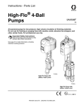
TI15594a
Models
Contents
Models . . . . . . . . . . . . . . . . . . . . . . . . . . . . . . . . . . . 2
4-Ball Lowers Cross Reference Chart . . . . . . . . . . 5
Warnings . . . . . . . . . . . . . . . . . . . . . . . . . . . . . . . . . 6
Changing the TSL . . . . . . . . . . . . . . . . . . . . . . . . . . 8
Repair . . . . . . . . . . . . . . . . . . . . . . . . . . . . . . . . . . . . 9
Replace the Throat Packings
Without Disconnecting the Lower . . . . . . . . . 9
TSL Pump Repair (if present) . . . . . . . . . . . . . . 10
Shield Disassembly/Reassembly . . . . . . . . . . . 10
Lower Disassembly . . . . . . . . . . . . . . . . . . . . . . 11
Lower Reassembly . . . . . . . . . . . . . . . . . . . . . . 15
Parts . . . . . . . . . . . . . . . . . . . . . . . . . . . . . . . . . . . . 17
Repair Kits, Related Manuals, and Accessories . 28
Technical Data . . . . . . . . . . . . . . . . . . . . . . . . . . . . 31
Graco Standard Warranty . . . . . . . . . . . . . . . . . . . 32
Graco Information . . . . . . . . . . . . . . . . . . . . . . . . . 32
Models
750cc Lowers
Model No. Series
Material
Maximum Pump
Working Pressure
psi (MPa, bar)
Rod/Cylinder
Material
Packings
Inlet/Outlet Fitting
Size and Type
Parts
Page
18
18
24F413
A
SST
460 (3.2, 32)
Chromex™/Chrome
UHMWPE/Leather
24F414
A
SST
460 (3.2, 32)
Chromex/MaxLife®
UHMWPE/Leather
24F420
A
CST
460 (3.2, 32)
Chromex/Nitride
UHMWPE/Leather
24F415
A
SST
460 (3.2, 32)
Chromex/Chrome
UHMWPE/Leather
Inlet: 1-1/2 in. npt
Outlet: 1 in. npt
Inlet: 1-1/2 in. npt
Outlet: 1 in. npt
Inlet: 1-1/2 in. npt
Outlet: 1 in. npt
1-1/2 in. tri-clamp
24F416
A
SST
460 (3.2, 32)
Chromex/MaxLife
UHMWPE/Leather
1-1/2 in. tri-clamp
18
24F417★
A
SST
460 (3.2, 32)
Chromex/Chrome
UHMWPE/Leather
1-1/2 in. tri-clamp
18
24F418★
A
SST
460 (3.2, 32)
Chromex/MaxLife
UHMWPE/Leather
1-1/2 in. tri-clamp
18
24F446★
A
SST
460 (3.2, 32)
Chromex/Chrome
UHMWPE/Leather
1-1/2 in. tri-clamp
21
Inlet: 1-1/2 in. npt
Outlet: 1 in. npt
Inlet: 1-1/2 in. npt
Outlet: 1 in. npt
Inlet: 1-1/2 in. npt
Outlet: 1 in. npt
18
18
18
Drum Size Lowers, with open wet-cup
24F421
A
SST
460 (3.2, 32)
Chromex™/Chrome
UHMWPE/Leather
24F422
A
SST
460 (3.2, 32)
Chromex/MaxLife®
UHMWPE/Leather
24F423
A
CST
460 (3.2, 32)
Chromex/Nitride
UHMWPE/Leather
18
18
★ These models are for use with Graco E-Flo Pumps only.
2
3A0539L
Models
1000cc Lowers
Model No. Series
Material
Maximum Pump
Working Pressure
psi (MPa, bar)
Rod/Cylinder
Material
Packings
Inlet/Outlet Fitting
Size and Type
Parts
Page
22
22
24F424
A
SST
460 (3.2, 32)
Chromex/Chrome
UHMWPE/Leather
24F425
A
SST
460 (3.2, 32)
Chromex/MaxLife
UHMWPE/Leather
24F431
A
CST
460 (3.2, 32)
Chromex/Chrome
UHMWPE/Leather
24F426
A
SST
460 (3.2, 32)
Chromex/Chrome
UHMWPE/Leather
Inlet: 1-1/2 in. npt
Outlet: 1 in. npt
Inlet: 1-1/2 in. npt
Outlet: 1 in. npt
Inlet: 1-1/2 in. npt
Outlet: 1 in. npt
1-1/2 in. tri-clamp
24F427
A
SST
460 (3.2, 32)
Chromex/MaxLife
UHMWPE/Leather
1-1/2 in. tri-clamp
22
24F428★
A
SST
460 (3.2, 32)
Chromex/Chrome
UHMWPE/Leather
1-1/2 in. tri-clamp
22
24F429★
A
SST
460 (3.2, 32)
Chromex/MaxLife
UHMWPE/Leather
1-1/2 in. tri-clamp
22
Material
Maximum Pump
Working Pressure
psi (MPa, bar)
Rod/Cylinder
Material
Packings
Inlet/Outlet Fitting
Size and Type
Parts
Page
24
24
22
22
1500cc Lowers
Model No. Series
24F432
A
SST
460 (3.2, 32)
Chromex/Chrome
UHMWPE/Leather
24F433
A
SST
460 (3.2, 32)
Chromex/MaxLife
UHMWPE/Leather
24F439
A
CST
460 (3.2, 32)
Chromex/Chrome
UHMWPE/Leather
24F434
A
SST
460 (3.2, 32)
Chromex/Chrome
UHMWPE/Leather
Inlet: 1-1/2 in. npt
Outlet: 1 in. npt
Inlet: 1-1/2 in. npt
Outlet: 1 in. npt
Inlet: 1-1/2 in. npt
Outlet: 1 in. npt
1-1/2 in. tri-clamp
24F435
A
SST
460 (3.2, 32)
Chromex/MaxLife
UHMWPE/Leather
1-1/2 in. tri-clamp
24
24F436★
A
SST
460 (3.2, 32)
Chromex/Chrome
UHMWPE/Leather
1-1/2 in. tri-clamp
24
24F437★
A
SST
460 (3.2, 32)
Chromex/MaxLife
UHMWPE/Leather
1-1/2 in. tri-clamp
24
Material
Maximum Pump
Working Pressure
psi (MPa, bar)
Rod/Cylinder
Material
Packings
Inlet/Outlet Fitting
Size and Type
Parts
Page
26
26
24
24
2000cc Lowers
Model No. Series
24F440
A
SST
460 (3.2, 32)
Chromex/Chrome
UHMWPE/Leather
24F447
A
CST
460 (3.2, 32)
Chromex/Chrome
UHMWPE/Leather
24F441
A
SST
460 (3.2, 32)
Chromex/Chrome
UHMWPE/Leather
Inlet: 1-1/2 in. npt
Outlet: 1 in. npt
Inlet: 1-1/2 in. npt
Outlet: 1 in. npt
1-1/2 in. tri-clamp
24F442
A
SST
460 (3.2, 32)
Chromex/MaxLife
UHMWPE/Leather
1-1/2 in. tri-clamp
26
24F443
A
SST
460 (3.2, 32)
Chromex/MaxLife
UHMWPE/Leather
26
24F444★
A
SST
460 (3.2, 32)
Chromex/Chrome
UHMWPE/Leather
Inlet: 1-1/2 in. npt
Outlet: 1 in. npt
1-1/2 in. tri-clamp
26
24F445★
A
SST
460 (3.2, 32)
Chromex/MaxLife
UHMWPE/Leather
1-1/2 in. tri-clamp
26
26
★ These models are for use with Graco E-Flo Pumps only.
3A0539L
3
Models
4
3A0539L
4-Ball Lowers Cross Reference Chart
4-Ball Lowers Cross Reference Chart
This chart cross references earlier styles of 4-ball lowers to the current lowers, which include the TSL pump and
spring loaded packings.
NOTE: Replacing an earlier lower with a current lower may require a retrofit connection kit, depending on the motor
used on your pump. See connection kit manual 311876 to order the correct kit for your lower and motor, if required.
Earlier Lower
Part No.
Current
Lower Part
No.
Earlier Lower
Part No.
Current
Lower Part
No.
Earlier Lower
Part No.
Current
Lower Part
No.
15D787
24F432
240608
24F426
253423
24F424
220547
24F420
24F428★
253520
24F426
220549
24F431
240609
24F424
220551
24F439
240610
24F415
220553
24F413
220555
24F424
240611
24F413
220557
24F432
240612
24F415
237220
24F413
237221
24F420
240613
24F413
239816
24F432
253033
24F424
239820
24F413
253034
24F432
239833
24F420
253035
24F440
239834
24F431
253061
24F431
239835
24F439
253062
24F439
239836
24F413
253063
24F447
239837
24F424
253085
24F432
239838
24F432
253086
24F440
239859
24F413
253396
24F443
239860
24F420
253397
24F433
240606
24F434
253398
24F425
240607
24F432
24F428★
253521
24F417★
24F417★
24F434
24F436★
253522
24F441
24F444★
253523
24F427
24F429★
253524
24F435
24F437★
253525
24F442
24F445★
253568
24F425
253569
24F433
253570
24F443
289366
24F415
24F417★
686679
24F413
★ These models are for use with Graco E-Flo Pumps only. When replacing an earlier style lower with a current
lower on an E-Flo pump, both lowers on the unit must be replaced.
3A0539L
5
Warnings
Warnings
The following warnings are for the setup, use, grounding, maintenance, and repair of this equipment. The exclamation point symbol alerts you to a general warning and the hazard symbols refer to procedure-specific risks. When
these symbols appear in the body of this manual, refer back to these Warnings. Product-specific hazard symbols and
warnings not covered in this section may appear throughout the body of this manual where applicable.
WARNING
WARNING
FIRE AND EXPLOSION HAZARD
Flammable fumes, such as solvent and paint fumes, in work area can ignite or explode. To help prevent
fire and explosion:
• Use equipment only in well ventilated area.
• Eliminate all ignition sources; such as pilot lights, cigarettes, portable electric lamps, and plastic drop
cloths (potential static arc).
• Keep work area free of debris, including solvent, rags and gasoline.
• Do not plug or unplug power cords, or turn power or light switches on or off when flammable fumes are
present.
• Ground all equipment in the work area. See Grounding instructions.
• Use only grounded hoses.
• Hold gun firmly to side of grounded pail when triggering into pail.
• If there is static sparking or you feel a shock, stop operation immediately. Do not use equipment until
you identify and correct the problem.
• Keep a working fire extinguisher in the work area.
Static charge may build up on plastic parts during cleaning and could discharge and ignite flammable
vapors. To help prevent fire and explosion:
•
Clean plastic parts only in a well ventilated area.
•
Do not clean with a dry cloth.
•
Do not operate electrostatic guns in equipment work area.
PRESSURIZED EQUIPMENT HAZARD
Fluid from the gun/dispense valve, leaks, or ruptured components can splash in the eyes or on skin and
cause serious injury.
• Follow the Pressure Relief Procedure when you stop spraying and before cleaning, checking, or
servicing equipment.
• Tighten all fluid connections before operating the equipment.
• Check hoses, tubes, and couplings daily. Replace worn or damaged parts immediately.
TOXIC FLUID OR FUMES HAZARD
Toxic fluids or fumes can cause serious injury or death if splashed in the eyes or on skin, inhaled, or
swallowed.
• Read MSDSs to know the specific hazards of the fluids you are using.
• Store hazardous fluid in approved containers, and dispose of it according to applicable guidelines.
6
3A0539L
Warnings
WARNING
WARNING
PERSONAL PROTECTIVE EQUIPMENT
You must wear appropriate protective equipment when operating, servicing, or when in the operating area
of the equipment to help protect you from serious injury, including eye injury, hearing loss, inhalation of
toxic fumes, and burns. This equipment includes but is not limited to:
• Protective eyewear, and hearing protection.
• Respirators, protective clothing, and gloves as recommended by the fluid and solvent manufacturer.
EQUIPMENT MISUSE HAZARD
Misuse can cause death or serious injury.
• Do not operate the unit when fatigued or under the influence of drugs or alcohol.
• Do not exceed the maximum working pressure or temperature rating of the lowest rated system
component. See Technical Data in all equipment manuals.
• Use fluids and solvents that are compatible with equipment wetted parts. See Technical Data in all
equipment manuals. Read fluid and solvent manufacturer’s warnings. For complete information about
your material, request MSDS from distributor or retailer.
• Do not leave the work area while equipment is energized or under pressure. Turn off all equipment and
follow the Pressure Relief Procedure when equipment is not in use.
• Check equipment daily. Repair or replace worn or damaged parts immediately with genuine
manufacturer’s replacement parts only.
• Do not alter or modify equipment.
• Use equipment only for its intended purpose. Call your distributor for information.
• Route hoses and cables away from traffic areas, sharp edges, moving parts, and hot surfaces.
• Do not kink or over bend hoses or use hoses to pull equipment.
• Keep children and animals away from work area.
• Comply with all applicable safety regulations.
MOVING PARTS HAZARD
Moving parts can pinch, cut or amputate fingers and other body parts.
• Keep clear of moving parts.
• Do not operate equipment with protective guards or covers removed.
• Pressurized equipment can start without warning. Before checking, moving, or servicing equipment,
follow the Pressure Relief Procedure and disconnect all power sources.
3A0539L
7
Changing the TSL
Changing the TSL
Check the condition of the TSL and the level in the reservoir every week, minimum. TSL should be changed at
least every month.
Part No. 206995 Throat Seal Liquid (TSL) carries residue from the pump rod into the reservoir. Discoloration
of the TSL fluid is to be expected during normal operation. After some time the TSL will thicken and darken,
and must be replaced. Thick, dirty TSL will not pump
through the lines and will harden in the pump wet-cup.
How long TSL lasts depends on which chemicals are
used, how much is used, what pressure, and condition
of the pump seal and rod.
A drop in the level of TSL in the reservoir indicates that
the throat packings are starting to wear. Add TSL to the
reservoir and keep the level above the Minimum fill line.
Monitor the usage and condition of the TSL. If pumped
material bypasses the throat packings and enters the
TSL reservoir, replace the packings.
To change the TSL:
To avoid the buildup of static charge, do not rub the
plastic bottle with a dry cloth while it is attached to the
pump. Remove the bottle to clean, if needed.
2. Remove and empty the reservoir bottle. Clean any
residue.
3. Clean screen (Z) of inlet check valve (48c‡). If check
valves are not sealing and dirty TSL is getting into
the wet-cup, replace the check valves (48c, 48d).
See FIG. 1.
NOTE: Order Check Valve Repair Kit 24F404. Kit parts
are marked with a symbol, for example (48b‡).
4. Fill the reservoir to the Maximum fill line with Throat
Seal Liquid (TSL).
5. Run pump. Each time pump rod reaches bottom of
stroke, check that some TSL is pumped from reservoir through wet-cup and back to reservoir.
1. Shut off the pump.
Outlet Check Valve
(48d‡)
Maximum Fill Line
48b‡
Minimum Fill Line
Inlet Check Valve
(48c‡)
Z
TI15853b
TI15857
FIG. 1. Cutaway of TSL Reservoir, and Fill Lines
8
3A0539L
Repair
Repair
Replace the Throat Packings
Without Disconnecting the
Lower
NOTE: Throat packing kits are available. See page 28.
Kit parts are marked with a symbol, for example (19†).
For best results, install the TSL Pump Repair Kit 24F617
each time the throat packings are changed.
NOTE: To replace the throat packings as part of a complete service of the lower, see page 11.
NOTE: Tool Kit 24F494 is available as an accessory.
The kit includes two wrenches for use with the wet-cup
(41) and throat cartridge (40).
1. Flush the pump, if possible.
2. Stop the pump at the middle of its stroke.
8. Lubricate the throat packings and glands. Install the
spring (43) and one male gland (19†) in the throat
cartridge (40), then five v-packings with the lips facing down: one UHMWPE (20†), one leather (25†),
UHMWPE, leather, UHMWPE. Install the female
gland (26†). Install three v-packings with the lips
facing up: UHMWPE, leather, UHMWPE. Install the
other male gland (19†).
9. Lubricate the o-ring (42†) and install it on the
wet-cup (41). Install the wet-cup finger-tight.
10. Install the o-ring (35†) on the throat cartridge (40).
Apply lubricant to the throat cartridge threads then
screw the cartridge into the outlet housing (16).
11. Torque the cartridge (40) to 95-100 ft-lb (129-135
N•m).
12. Torque the wet-cup (41) to 70-75 ft-lb (95-102 N•m).
13. Reassemble the spring (45◆), TSL pump piston
seal (46◆), and o-rings (47◆).
3. Relieve the pressure. See your separate pump manual.
4. Following the instructions in your separate pump
manual, remove the 2-piece shield covering the coupling assembly. Unscrew the coupling nut from the
motor shaft. Lift the motor shaft and remove the
coupling nut and collars.
5. See FIG. 4. Remove the collar (50) and screws (51),
cap (49), and manifold and bottle assembly (48).
14. Reassemble the manifold and bottle assembly (48),
cap (49), collar (50) and screws (51). Torque the cap
(49) to 25-30 ft-lb (34-40 N•m).
15. Reinstall the coupling nut and collars on the piston
rod (17).
16. Reconnect the coupling nut to the motor shaft. See
your separate pump assembly manual for correct
torque specifications for your model. Reinstall the
shield.
6. Remove the wet-cup (41) and o-ring (42). Remove
the TSL pump piston seal (46◆), spring (45◆), and
o-rings (47◆).
7. Remove the throat cartridge (40). Remove the
o-ring (35), glands (19, 26), packings (20, 25), and
spring (43).
NOTE: Inspect the surface of the piston rod (17). If it is
scratched, replace the piston rod.
3A0539L
9
Repair
TSL Pump Repair (if present)
Table 1: TSL Pump Troubleshooting
Problem
TSL pump not pumping TSL fluid.
Cause
Solution
Plugged manifold (48a).
Clear the manifold. Verify that the manifold is clear by blowing compressed air
through the opening.
Plugged check valves (48c, 48d).
Clear obstruction in check valves.
Plugged inlet strainer (48c).
Clear strainer mesh.
Damaged TSL pump piston (46).
Replace TSL pump piston.
NOTE: TSL Pump Repair Kit 24F617 is available. See
page 28. Install the TSL Pump Repair Kit 24F617 each
time the throat packings are changed. Kit parts are
marked with a symbol, for example (46◆).
1. Follow steps 1-6 under Replace the Throat Packings Without Disconnecting the Lower, page 9.
2. Clean all parts and inspect for damage.
3. Follow steps 12-16 under Replace the Throat
Packings Without Disconnecting the Lower.
Shield Disassembly/Reassembly
Some lowers include shield kits in multiple sizes. The
correct size is determined by your lower and motor. See
manual 406876 to select the correct size kit for your
lower and motor.
See FIG. 2. Remove the 2-piece shield (52) by inserting
a screwdriver straight into the slot, and using it as a
lever to release the tab. Repeat for all tabs. Do not use
the screwdriver to pry the shields apart.
Install the shields (52) by engaging the bottom lips with
the groove in the wet-cup cap (49). Snap the two shields
together.
Shield Disassembly
Shield Reassembly
ti15758a
ti15759a
ti15757a
ti15770a
49
52
FIG. 2. Disassembly and Reassembly of the Shields
10
3A0539L
Repair
Lower Disassembly
NOTE: Seal kits are available for each lower size. See
page 28. Kit parts are marked with an asterisk in the text
and drawings, for example (2*).
NOTE: Throat packing kits are available. See page 28.
Kit parts are marked with a symbol, for example (19†).
For best results, install the TSL Pump Repair Kit 24F617
each time the throat packings are changed.
NOTE: Tool Kit 24F494 is available as an accessory.
The kit includes two wrenches for use with the wet-cup
(41) and throat cartridge (40).
NOTE: Complete pump repair kits are also available.
The kits include all seal kit parts, throat packing kit parts,
and TSL pump repair kit parts. See page 28.
6. Secure the inlet manifold (18) in a vise.
7. Loosen, but do not remove, the wet-cup (41) and
cartridge (40).
8. Remove the four capscrews (9) and washers (8)
from around the outlet manifold (22).
9. Remove the outlet manifold (22), balls (23), seats
(24), and gaskets (7).
10. Remove the wet-cup (41) and o-ring (42). Remove
the TSL pump piston seal (46), spring (45), and
o-rings (47).
11. Remove the throat cartridge (40). Remove the
o-ring (35), glands (19, 26), packings (20, 25), and
spring (43).
1. Flush the pump, if possible.
2. Stop the pump at the middle of its stroke.
3. Relieve the pressure. See your separate pump manual.
4. Remove the lower from the motor as described in
your separate pump manual.
NOTE: See FIG. 4 for an exploded view of the entire
lower. See FIG. 5 for a cutaway view of the lower and an
exploded view of the throat packings and TSL pump.
5. Remove the collar (50) and screws (51), cap (49),
and manifold and bottle assembly (48).
12. Remove the three cylinder screws (13) and lockwashers (14). Lift off the outlet housing (16).
NOTE: The fluid tubes (3), cylinder (1), and piston
assembly (17, 10, 11, 44, 12) may come loose with the
outlet housing, or may remain in place on the inlet housing (15).
13. Remove the tubes (3) and cylinder (1). Pull the piston assembly out of the cylinder. Inspect the surface
of the piston rod (17) and the inside surfaces of the
cylinder and tubes. If any of these parts are
scratched or damaged, replace them.
14. Remove the inlet manifold (18) from the vise.
15. Remove the four capscrews (9) and washers (8)
from the inlet manifold (18).
NOTE: To replace the check valves in the TSL bottle,
order Check Valve Repair Kit 24F404. Kit parts are
marked with a symbol, for example (48b‡). To replace
the bottle only, order Bottle Replacement Kit 24F405. Kit
parts are marked with a symbol, for example (48e❄).
The kit includes 5 bottles and 5 labels. See FIG. 1, FIG.
4, and FIG. 5.
3A0539L
11
Repair
NOTE: One inlet seat (6) includes a pressure relief
valve. See FIG. 3. This seat must be located exactly
where shown (the left side as viewed in FIG. 4). Use the
text cast into the inlet housing as a guide.
18. Place the flats of the piston nut (12) in a vise.
Unscrew the rod (17) from the nut. Remove the
spacer (44). Disassemble the piston (10) and
remove the seal (11).
16. Remove the balls (5), inlet seats (6 and 33), and
gaskets (7).
NOTE: The piston spacer (44) is not present on 750cc
lowers.
NOTICE
Be careful not to drop or damage the balls (5) or seats
(6 and 33). A damaged ball or seat cannot seal properly and the pump will leak. One inlet valve seat (33)
can be reversed to provide longer use of the seat.
However, the fluid inlet seat (6) contains a pressure
relief valve and is not reversible. See FIG. 3 for proper
orientation.
19. Clean all parts in a compatible solvent. Inspect all
parts for wear or damage. If you are using a repair
kit, use all the new parts in the kit, discarding the old
ones they replace. Replace any other parts as
needed. Worn or damaged parts may cause the
pump to perform poorly or cause premature wear of
the new seals and packings.
17. Inspect the pressure relief valve in the seat (6) to
make sure it is not clogged. Press down on the
valve's ball to see if the ball and the spring are free
to move. See FIG. 3.
pin
7
ball
spring
pressure relief valve
6
TI8407a
FIG. 3. Inlet Seat with Pressure Relief Valve
NOTICE
If the pressure relief valve in the seat (6) is clogged or
filled with material, soak the seat in a compatible solvent. Make sure all material residue is cleaned from
the ball and seat area.
If the relief valve cannot be thoroughly cleaned so that
the ball and spring are free to move, replace the seat
(6).
12
3A0539L
Repair
50
51
2
5
9
5
8
49
22
46◆
48a
10
23
24
48f
45◆
1
1
‡48d
‡48b
1
47◆
16
44
41
42†
19†
20†
25†
20†
26†
20†
25†
❄48e
1
43
40
4*
*2
12
17
6
3
14
15
1
5
5
*2
6
33
1
*7
7*
1
1
1
20†
7
10
8
7
‡48c
6
11*
*7
25†
20†
19†
18
13
8
1
1
7
*4
4
9
†35
3
5
2
TI15433c
1
Apply lubricant to all packings and
seals.
2
Apply removable (blue) Loctite® 243 to
entire length of threads.
3
4
Apply high strength (red) Loctite® 263 or
2760 to entire length of threads. Sealant
must be allowed to cure for a minimum
of 12 hours before use.
Tighten uniformly until cylinder (4) is
seated. Torque to 25-30 ft-lb (34-40
N•m).
5
Torque 25-30 ft-lb (34-40 N•m).
6
Torque 95-100 ft-lb (129-135 N•m).
7
Apply thread lubricant.
8
Torque 70-75 ft-lb (95-102 N•m).
FIG. 4. Exploded View of Lower
3A0539L
13
Repair
49
50, 51
46◆
48a
OUTLET
◆45
22
48f
◆47
23
48d‡
48b‡
16
41
7*, 24
4*
*2
10
3
11*
†42
†19
†20
†25
†20
†26
†20
†25
†20
48c‡
†25
†20
17
†19
1
13
44
48e❄
43
40
35†
12
TI15435c
*2
5
5
6
33
15
7*
*7
18
INLET
TI15434b
FIG. 5. Cutaway View of Lower
14
3A0539L
Repair
Lower Reassembly
1. See FIG. 4. Place the halves of the piston (10)
around the packing (11) and snap them together.
5. Install the inlet seat without a relief valve (33) in the
right side of the inlet housing (15).
2. Apply high strength (red) Loctite® 263 or 2760 to
entire length of the piston rod (17) threads. Sealant
must be allowed to cure for a minimum of 12 hours
before use. Screw the rod through the piston and
spacer (44) and into the piston nut (12). Torque the
nut to 95-100 ft-lb (129-135 N•m).
NOTE: The inlet seats (6 and 33) are not reversible; the
chamfered side must face the ball.
3. With the inlet housing (15) turned upside down,
install the balls (5) and the gaskets (7*).
COMPONENT RUPTURE HAZARD
The relief valve seat (6) must be installed at the fluid
inlet, as shown in FIG. 4 and FIG. 5. The relief valve
reduces the risk of pump overpressurization. The seat
cannot relieve pressure if installed on the other side of
the inlet housing.
4. Install the relief valve inlet seat (6) in the left side of
the inlet housing (15), as viewed in FIG. 4 and FIG.
5. (Text cast into the inlet housing identifies the correct location for the relief valve seat.) The pin (P) on
the seat must point into the housing. The pin limits
the positioning of the seat, ensuring that the vent is
not blocked by part of the housing. See FIG. 6.
6. Place the inlet manifold (18) on the inlet housing
(15). Apply removable (blue) Loctite® 243 to entire
length of the screw (9) threads. Install the lockwashers (8) and screws (9), and torque to 25-30 ft-lb
(34-40 N•m).
7. Place the inlet manifold (18) in a vise. Place one
o-ring (2*) in each side of the inlet housing (15),
where the tubes (3) sit. Place o-rings (2*) in the
grooves at each end of the tubes. Place a gasket (4)
in both the inlet and outlet housing (15 and 16).
Position the tubes and cylinder (1) in the inlet housing.
NOTE: It may be necessary to use a rubber mallet to set
the fluid tubes (3) and cylinder (4) in place.
8. Lubricate the inside of the cylinder (4). Slide the piston assembly into the cylinder. Rotate the piston as
shown in FIG. 7.
P
7
ball
spring
pressure relief valve
TI8734a
6
TI8407a
FIG. 7. Install Piston in Cylinder
FIG. 6. Inlet Seat with Pressure Relief Valve
3A0539L
15
Repair
9. Lubricate the throat packings and glands. Install the
spring (43) and one male gland (19†) in the throat
cartridge (40), then five v-packings with the lips facing down: one UHMWPE (20†), one leather (25†),
UHMWPE, leather, UHMWPE. Install the female
gland (26†). Install three v-packings with the lips
facing up: UHMWPE, leather, UHMWPE. Install the
other male gland (19†).
10. Lubricate the o-ring (42†) and install it on the
wet-cup (41). Install the wet-cup finger-tight.
11. Install the o-ring (35†) on the throat cartridge (40).
Apply lubricant to the throat cartridge threads then
screw the cartridge into the outlet housing (16)
loosely.
12. Install the outlet housing (16). It may not seat well
on the tubes and cylinder. Install the screws (13)
and lockwashers (14) from the inlet housing (15). As
you tighten the screws into the outlet housing (16),
they will draw the housings firmly onto the tubes and
cylinders. Tighten the screws uniformly and torque
to 25-30 ft-lb (34-40 N•m).
15. Place a ball (23), seat (24) and gasket (7*) in each
side of the outlet manifold (22). Install the outlet
manifold on the outlet housing (16).
16. Apply removable (blue) Loctite® 243 to entire length
of the screw (9) threads. Install the lockwashers (8)
and screws (9), and torque to 25-30 ft-lb (34-40
N•m).
NOTE: The outlet seats (24) are reversible.
17. Reassemble the spring (45), TSL pump piston seal
(46), and o-rings (47).
18. Reassemble the manifold and bottle assembly (48),
cap (49), collar (50) and screws (51). Torque the cap
(49) to 25-30 ft-lb (34-40 N•m).
19. Reinstall the coupling nut and collars on the piston
rod (17).
20. Fill the cavity in the bottom of the motor shaft with
grease. Reconnect the lower to the motor as
described in your separate pump manual.
13. Torque the cartridge (40) to 95-100 ft-lb (129-135
N•m).
14. Torque the wet-cup (41) to 70-75 ft-lb (95-102 N•m).
16
3A0539L
Parts
Parts
50
51
See Parts Lists:
750cc, pages 18-19
1000cc, pages 22-23
1500cc, pages 24-25
2000cc, pages 26-27
9
49
46◆
48a
8
22
10
23
24
48f
45◆
*7
11*
47◆
16
10
‡48d
‡48b
‡48c
41
42†
19†
20†
25†
20†
26†
20†
25†
❄48e
20†
43
40
25†
20†
44
*2
4*
12
17
3
14
15
1
*2
19†
5
5
6
33
*7
7*
18
13
8
*4
9
†35
TI15433b
Open Wet-Cup (Drum Size only)
Shields (shipped loose)
52
49
◆47
39
41
TI15611a
3A0539L
ti15757a
17
Parts
750cc Lowers
Part No. 24F413, Series A, Stainless Steel
Part No. 24F414, Series A, Stainless Steel
Part No. 24F420, Series A, Carbon Steel
Part No. 24F415, Series A, Stainless Steel
Part No. 24F416, Series A, Stainless Steel
Part No. 24F417★, Series A, Stainless Steel
Part No. 24F418★, Series A, Stainless Steel
Part No. 24F421, Series A, Stainless Steel, Drum Size, with open wet-cup
Part No. 24F422, Series A, Stainless Steel, Drum Size, with open wet-cup
Part No. 24F423, Series A, Carbon Steel, Drum Size, with open wet-cup
Ref.
No. Description
1
CYLINDER, pump;
sst/chrome
CYLINDER, pump;
sst/MaxLife
CYLINDER, pump;
cst/nitride
2*
PACKING, o-ring; PTFE
3
TUBE, fluid; sst
4*
GASKET, cylinder;
UHMWPE
5
BALL, inlet; 1.25 in. dia; sst
6
SEAT, inlet valve, with relief
valve; sst
7*
GASKET, seat, valve;
UHMWPE
8
WASHER, flat; 8.4 mm; sst
9
CAPSCREW, hex hd; M8 x
1.25 x 25; sst
CAPSCREW, hex hd; M8 x
1.25 x 25; cst
10
PISTON
11* PACKING, piston;
UHMWPE
12
NUT, piston
13
CAPSCREW, hex hd;
9/16-12 unc x 7.5 in.; sst
CAPSCREW, hex hd;
9/16-12 unc x 7.5 in.; cst
14
LOCKWASHER, spring;
9/16 in.; sst
LOCKWASHER, spring;
9/16 in.; cst
15
HOUSING, inlet; sst
HOUSING, inlet; cst
HOUSING, inlet; sst
16
HOUSING, outlet; sst
HOUSING, outlet; cst
17
ROD, piston; sst
18
MANIFOLD, inlet; npt; sst
MANIFOLD, inlet; npt; cst
MANIFOLD, inlet; tri-clamp;
sst
18
Lower
24F413 24F414 24F420 24F415 24F416 24F417★ 24F418★ 24F421 24F422 24F423 Qty
183049
183049
183049
183049
1
24A343
24A343
24A343
24A343
181899
1
181899
1
n/a
n/a
n/a
n/a
n/a
n/a
183085 183085 183085 183085 183085 183085
n/a
n/a
n/a
n/a
n/a
n/a
n/a
183085
n/a
n/a
n/a
n/a
183085 183085 183085
n/a
n/a
n/a
6
2
2
101968 101968 101968 101968 101968 101968
253483 253483 253483 253483 253483 253483
101968
253483
101968 101968 101968
253483 253483 253483
2
1
n/a
n/a
n/a
4
111003
112084
111003 111003 111003
112084 112084
8
8
107558
8
n/a
n/a
n/a
n/a
n/a
111003 111003 111003 111003 111003 111003
112084 112084 112084
112084 112084
n/a
107558
n/a
16A249 16A249 16A249 16A249 16A249 16A249
n/a
n/a
n/a
n/a
n/a
n/a
16A249
n/a
16A249 16A249 16A249
n/a
n/a
n/a
2
1
108528 108528 108528 108528 108528 108528
120199 120199 120199
120199 120199
108528
120199
108528 108528 108528
120199 120199
1
3
120446
3
120446
108525 108525 108525
108525 108525
108525
108525 108525
101333
101333
16D846 16D846
16D846 16D846
16D846 16D846
16D848
16D847 16D847
3
16D848
16E907
16D847 16D847 16D847
16D849
16A462 16A462 16A462 16A462 16A462 16A462
192259 192259
192260
15H663 15H663 15H663
16E907
16D847
16A462
15H663
16D847 16D847
16D849
16A462 16A462 16A462
192259 192259
192260
3
1
1
1
1
1
1
1
1
1
3A0539L
Parts
Ref.
No. Description
19† GLAND, male; sst
20† V-PACKING, throat;
UHMWPE
22
MANIFOLD, outlet; npt; sst
MANIFOLD, outlet; npt; cst
MANIFOLD, outlet;
tri-clamp; sst
MANIFOLD, outlet;
tri-clamp; sst
23
BALL, outlet; 1 in.
(25 mm) dia.; sst
24** SEAT, outlet valve; sst
25† V-PACKING, throat; leather
26† GLAND, female; sst
33
SEAT, inlet valve; sst
35† PACKING, o-ring; PTFE
36▲ TAG, warning; not shown
39
SPACER, open wet-cup
40
CARTRIDGE, throat
41
WET CUP
42† PACKING, o-ring; PTFE
43
SPRING
45◆ SPRING
46◆ SEAL, piston, TSL pump
47◆ O-RING
48
MANIFOLD/BOTTLE;
includes 48a-48f
48a MANIFOLD; nylon
48b‡ NIPPLE; sst
48c‡ INLET CHECK; nylon, sst,
fluoroelastomer
48d‡ OUTLET CHECK; nylon,
sst, pvc, fluoroelastomer
48e❄ BOTTLE; hdpe
48f O-RING
49
CAP, wet-cup
50
COLLAR, piston rod
51
SCREW; M4 x 12
52
SHIELD KITS; some lowers
include shield kits in multiple sizes; see manual
406876 to select the correct size kit for your lower
and motor
Lower
24F413 24F414 24F420 24F415 24F416 24F417★ 24F418★ 24F421 24F422 24F423 Qty
n/a
n/a
n/a
n/a
n/a
n/a
n/a
n/a
n/a
n/a
2
n/a
n/a
n/a
n/a
n/a
n/a
n/a
n/a
n/a
n/a
5
15G873 15G873
15G873 15G873
181728
181728
15H664 15H664
1
1
1
16E906
16E906
110259 110259 110259 110259 110259 110259
110259
110259 110259 110259
2
183095
n/a
n/a
239865
n/a
172479
183095
n/a
n/a
239865
n/a
172479
183095
n/a
n/a
239865
n/a
172479
183095
n/a
n/a
236865
n/a
172479
183095
n/a
n/a
239865
n/a
172479
183095
n/a
n/a
239865
n/a
172479
183095
n/a
n/a
239865
n/a
172479
16A464
16A463
n/a
16A547
n/a
n/a
108657
24T074
16A464
16A463
n/a
16A547
n/a
n/a
108657
24T074
16A464
16A463
n/a
16A547
n/a
n/a
108657
24T074
16A464
16A463
n/a
16A547
n/a
n/a
108657
24T074
16A464
16A463
n/a
16A547
n/a
n/a
108657
24T074
16A464
16A463
n/a
16A547
n/a
n/a
108657
24T074
16A464
16A463
n/a
16A547
n/a
n/a
108657
24T074
183095
n/a
n/a
239865
n/a
172479
16E083
16A464
16A463
n/a
16A547
2
3
1
1
1
1
1
1
1
1
1
1
1
2
1
n/a
n/a
n/a
n/a
n/a
n/a
n/a
n/a
n/a
n/a
n/a
n/a
n/a
n/a
n/a
n/a
n/a
n/a
n/a
n/a
n/a
1
1
1
n/a
n/a
n/a
n/a
n/a
n/a
n/a
1
n/a
16G290
16F050
16E414
115263
1
1
1
2
2
1
n/a
n/a
n/a
n/a
n/a
n/a
16G290 16G290 16G290 16G290 16G290 16G290
16F050 16F050 16F050 16F050 16F050 16F050
16E414 16E414 16E414 16E414 16E414 16E414
115263 115263 115263 115263 115263 115263
24A640 24A640 24A640 24A640 24A640
24F252 24F252 24F252 24F252 24F252
24F253
1
183095
n/a
n/a
239865
n/a
172479
16E083
16A464
16A463
n/a
16A547
183095
n/a
n/a
239865
n/a
172479
16E083
16A464
16A463
n/a
16A547
108657 108657 108657
16F050 16F050 16F050
24F253
Click here to return to repair kit page.
★ These models are for use with Graco E-Flo Pumps only.
◆ Parts included in TSL Pump Repair Kit 24F617 (purchase
separately).
▲ Replacement Danger and Warning labels, tags, and cards
are available at no cost.
❄ Order TSL Bottle Replacement Kit 24F405 (purchase separately). Includes 5 bottles.
* Parts included in Seal Repair Kit 16E904 (purchase separately).
‡ Parts included in TSL Check Valve Repair Kit 24F404 (purchase separately).
† Parts included in Throat Packing Repair Kit 24F245 (purchase separately).
Complete Pump Repair Kit 24F660 is available (purchase separately).
** Carbide Seat Kit 24F249 is available for applications causing excessive wear (purchase separately).
Parts labeled n/a are not available separately.
3A0539L
19
Parts
20
3A0539L
Parts
Part No. 24F446★, Series A, Stainless Steel (see 406865 for details)
Ref.
No.
1
2*
3
4*
5
6
7*(**)
8
9
Description
CYLINDER, pump; sst/chrome
PACKING, o-ring; PTFE
TUBE, fluid; sst
GASKET, cylinder; UHMWPE
BALL, inlet; 1.25 in. dia; sst
SEAT, inlet valve, with relief valve; sst
GASKET, seat, valve; UHMWPE
WASHER, flat; 8.4 mm; sst
CAPSCREW, hex hd; M8 x 1.25 x 25;
sst
10
PISTON
11* PACKING, piston; UHMWPE
12
NUT, piston
13
CAPSCREW, hex hd; 9/16-12 unc x 7.5
in.; sst
14
LOCKWASHER, spring; 9/16 in.; sst
15
HOUSING, inlet; sst
16
HOUSING, outlet; sst
17
ROD, piston; sst
18
MANIFOLD, inlet; tri-clamp; sst
19† GLAND, male; sst
20† V-PACKING, throat; UHMWPE
22
MANIFOLD, outlet; tri-clamp; sst
23(**) BALL, outlet; 1 in. (25 mm) dia.; sst
24(**) SEAT, outlet valve; sst
25† V-PACKING, throat; leather
26† GLAND, female; sst
33
SEAT, inlet valve; sst
35† PACKING, o-ring; PTFE
36▲ TAG, warning; not shown
40
CARTRIDGE, throat
41
WET CUP
3A0539L
Click here to return to repair kit page.
★ These models are for use with Graco E-Flo Pumps only.
Lower
24F446★ Qty
183049
1
n/a
6
183085
2
n/a
2
101968
2
253483
1
n/a
4
111003
8
112084
8
16A249
n/a
108528
120199
2
1
1
3
108525
16E907
16D847
16A462
15H663
n/a
n/a
16E906
110259
183095
n/a
n/a
239865
n/a
172479
16E926
181684
3
1
1
1
1
2
5
1
2
2
3
1
1
1
1
1
1
▲ Replacement Danger and Warning labels, tags, and cards
are available at no cost.
*
Parts included in Seal Repair Kit 16E904 (purchase separately).
†
Parts included in Throat Packing Repair Kit 24F245 (purchase separately).
** Carbide Seat Kit 24F249 is available for applications causing excessive wear (purchase separately).
Complete Pump Repair Kit 24F660 is available (purchase separately).
Parts labeled n/a are not available separately.
21
Parts
1000cc Lowers
Part No. 24F424, Series A, Stainless Steel
Part No. 24F425, Series A, Stainless Steel
Part No. 24F431, Series A, Carbon Steel
Part No. 24F426, Series A, Stainless Steel
Part No. 24F427, Series A, Stainless Steel
Part No. 24F428★, Series A, Stainless Steel
Part No. 24F429★, Series A, Stainless Steel
Ref.
No.
1
2*
3
4*
5
6
7*
8
9
10
11*
12
13
14
15
16
17
18
19†
20†
22
Lower
Description
CYLINDER, pump; sst/chrome
CYLINDER, pump; sst/MaxLife
PACKING, o-ring; PTFE
TUBE, fluid; sst
GASKET, cylinder; UHMWPE
BALL, inlet; 1.25 in. dia; sst
SEAT, inlet valve, with relief valve; sst
GASKET, seat, valve; UHMWPE
WASHER, flat; 8.4 mm; sst
CAPSCREW, hex hd; M8 x 1.25 x 25;
sst
CAPSCREW, hex hd; M8 x 1.25 x 25;
cst
PISTON
PACKING, piston; UHMWPE
NUT, piston
CAPSCREW, hex hd; 9/16-12 unc x 7.5
in.; sst
CAPSCREW, hex hd; 9/16-12 unc x 7.5
in.; cst
LOCKWASHER, spring; 9/16 in.; sst
LOCKWASHER, spring; 9/16 in.; cst
HOUSING, inlet; sst
HOUSING, inlet; cst
HOUSING, inlet; sst
HOUSING, outlet; sst
HOUSING, outlet; cst
ROD, piston; sst
MANIFOLD, inlet; npt; sst
MANIFOLD, inlet; npt; cst
MANIFOLD, inlet; tri-clamp; sst
GLAND, male; sst
V-PACKING, throat; UHMWPE
24F424
183047
n/a
183085
n/a
101968
253483
n/a
111003
112084
24F425
15H452
n/a
183085
n/a
101968
253483
n/a
111003
112084
24F431
183047
24F426
183047
n/a
183085
n/a
101968
253483
n/a
111003
n/a
183085
n/a
101968
253483
n/a
111003
112084
24F427
15H452
n/a
183085
n/a
101968
253483
n/a
111003
112084
24F428★ 24F429★
183047
15H452
n/a
n/a
183085 183085
n/a
n/a
101968 101968
253483 253483
n/a
n/a
111003 111003
112084 112084
107558
15G883
n/a
15H989
120199
15G883
n/a
15H989
120199
15G883
n/a
15H989
8
15G883
n/a
15H989
120199
15G883
n/a
15H989
120199
15G883
n/a
15H989
120199
15G883
n/a
15H989
120199
120446
108525
108525
16D846
108525
108525
108525
108525
16D846
16D846
16D847
16D847
16E907
16D847
16E907
16D847
16A462
16A462
16A462
16A462
15H663
n/a
n/a
15H663
n/a
n/a
15H663
n/a
n/a
15H663
n/a
n/a
16D848
16D847
16D847
16A462
192259
16A462
192259
16D849
16A462
192260
n/a
n/a
n/a
n/a
n/a
n/a
2
1
1
3
3
101333
16D846
Qty
1
1
6
2
2
2
1
4
8
8
3
3
1
1
1
1
1
1
1
1
1
2
5
3A0539L
Parts
Ref.
No.
22
Description
MANIFOLD, outlet; npt; sst
MANIFOLD, outlet; npt; cst
MANIFOLD, outlet; tri-clamp; sst
MANIFOLD, outlet; tri-clamp; sst
23
BALL, outlet; 1 in. (25 mm) dia.; sst
24** SEAT, outlet valve; sst
25†
V-PACKING, throat; leather
26†
GLAND, female; sst
33
SEAT, inlet valve; sst
35†
PACKING, o-ring; PTFE
36▲ TAG, warning (not shown)
40
CARTRIDGE, packing, throat
41
WET CUP
42†
PACKING, o-ring; PTFE
43
SPRING
44
SPACER, piston
45◆ SPRING
46◆ SEAL, piston, TSL pump
47◆ O-RING
48
MANIFOLD/BOTTLE; includes 48a-48f
48a
MANIFOLD; nylon
48b‡ NIPPLE; sst
48c‡ INLET CHECK; nylon, sst,
fluoroelastomer
48d‡ OUTLET CHECK; nylon, sst, pvc,
fluoroelastomer
48e❄ BOTTLE; hdpe
48f
O-RING
49
CAP, wet-cup
50
COLLAR, piston rod
51
SCREW; M4 x 12
52
SHIELD KITS; some lowers include
shield kits in multiple sizes; see manual
406876 to select the correct size kit for
your lower and motor
Lower
24F424
15G873
24F425
15G873
24F431
24F426
24F427
15H664
15H664
24F428★ 24F429★
181728
Qty
1
1
1
1
2
2
3
1
1
1
1
1
1
1
1
1
1
1
2
1
1
1
1
110259
183095
n/a
n/a
239865
n/a
172479
16A464
16A463
n/a
16A547
16D850
n/a
n/a
108657
24T074
n/a
n/a
n/a
110259
183095
n/a
n/a
239865
n/a
172479
16A464
16A463
n/a
16A547
16D850
n/a
n/a
108657
24T074
n/a
n/a
n/a
110259
183095
n/a
n/a
239865
n/a
172479
16A464
16A463
n/a
16A547
16D850
n/a
n/a
108657
24T074
n/a
n/a
n/a
110259
183095
n/a
n/a
236865
n/a
172479
16A464
16A463
n/a
16A547
16D850
n/a
n/a
108657
24T074
n/a
n/a
n/a
110259
183095
n/a
n/a
239865
n/a
172479
16A464
16A463
n/a
16A547
16D850
n/a
n/a
108657
24T074
n/a
n/a
n/a
16E906
110259
183095
n/a
n/a
239865
n/a
172479
16A464
16A463
n/a
16A547
16D850
n/a
n/a
108657
24T074
n/a
n/a
n/a
16E906
110259
183095
n/a
n/a
239865
n/a
172479
16A464
16A463
n/a
16A547
16D850
n/a
n/a
108657
24T074
n/a
n/a
n/a
n/a
n/a
n/a
n/a
n/a
n/a
n/a
1
n/a
16G290
16F050
16E414
115263
24A640
24F251
24F252
n/a
16G290
16F050
16E414
115263
24A640
24F251
24F252
n/a
16G290
16F050
16E414
115263
24A640
24F251
24F252
n/a
16G290
16F050
16E414
115263
24A640
24F251
24F252
n/a
16G290
16F050
16E414
115263
24A640
24F251
24F252
n/a
16G290
16F050
16E414
115263
n/a
16G290
16F050
16E414
115263
1
1
1
2
2
1
24F253
24F253
Click here to return to repair kit page.
★ These models are for use with Graco E-Flo Pumps only.
▲ Replacement Danger and Warning labels, tags, and cards are available at no cost.
*
Parts included in Seal Repair Kit 277360 (purchase separately).
†
Parts included in Throat Packing Repair Kit 24F245 (purchase separately).
** Carbide Seat Kit 24F249 is available for applications causing excessive wear (purchase separately).
◆ Parts included in TSL Pump Repair Kit 24F617 (purchase separately).
❄ Order TSL Bottle Replacement Kit 24F405 (purchase separately). Includes 5 bottles.
‡
Parts included in TSL Check Valve Repair Kit 24F404 (purchase separately).
Complete Pump Repair Kit 24F661 is available (purchase separately).
Parts labeled n/a are not available separately.
3A0539L
23
Parts
1500cc Lowers
Part No. 24F432, Series A, Stainless Steel
Part No. 24F433, Series A, Stainless Steel
Part No. 24F439, Series A, Carbon Steel
Part No. 24F434, Series A, Stainless Steel
Part No. 24F435, Series A, Stainless Steel
Part No. 24F436★, Series A, Stainless Steel
Part No. 24F437★, Series A, Stainless Steel
Ref.
No.
1
2*
3
4*
5
6
7*
8
9
10
11*
12
13
14
15
16
17
18
19†
20†
24
Lower
Description
CYLINDER, pump; sst/chrome
CYLINDER, pump; sst/MaxLife
PACKING, o-ring; PTFE
TUBE, fluid; sst
GASKET, cylinder; UHMWPE
BALL, inlet; 1.25 in. dia; sst
SEAT, inlet valve, with relief valve; sst
GASKET, seat, valve; UHMWPE
WASHER, flat; 8.4 mm; sst
CAPSCREW, hex hd; M8 x 1.25 x 25;
sst
CAPSCREW, hex hd; M8 x 1.25 x 25;
cst
PISTON
PACKING, piston; UHMWPE
NUT, piston
CAPSCREW, hex hd; 9/16-12 unc x 7.5
in.; sst
CAPSCREW, hex hd; 9/16-12 unc x 7.5
in.; cst
LOCKWASHER, spring; 9/16 in.; sst
LOCKWASHER, spring; 9/16 in.; cst
HOUSING, inlet; sst
HOUSING, inlet; cst
HOUSING, inlet; sst
HOUSING, outlet; sst
HOUSING, outlet; cst
ROD, piston; sst
MANIFOLD, inlet; npt; sst
MANIFOLD, inlet; npt; cst
MANIFOLD, inlet; tri-clamp; sst
GLAND, male; sst
V-PACKING, throat; UHMWPE
24F432
183048
n/a
183085
n/a
101968
253483
n/a
111003
112084
24F433
15H453
n/a
183085
n/a
101968
253483
n/a
111003
112084
24F439
183048
24F434
183048
n/a
183085
n/a
101968
253483
n/a
111003
n/a
183085
n/a
101968
253483
n/a
111003
112084
24F435
15H453
n/a
183085
n/a
101968
253483
n/a
111003
112084
24F436★ 24F437★
183048
15H453
n/a
n/a
183085 183085
n/a
n/a
101968 101968
253483 253483
n/a
n/a
111003 111003
112084 112084
107558
15G884
n/a
15H989
120199
15G884
n/a
15H989
120199
15G884
n/a
15H989
8
15G884
n/a
15H989
120199
15G884
n/a
15H989
120199
15G884
n/a
15H989
120199
15G884
n/a
15H989
120199
120446
108525
108525
16D846
108525
108525
108525
108525
16D846
16D846
16D847
16D847
16E907
16D847
16E907
16D847
16A462
16A462
16A462
16A462
15H663
n/a
n/a
15H663
n/a
n/a
15H663
n/a
n/a
15H663
n/a
n/a
16D848
16D847
16D847
16A462
192259
16A462
192259
16D849
16A462
192260
n/a
n/a
n/a
n/a
n/a
n/a
2
1
1
3
3
101333
16D846
Qty
1
1
6
2
2
2
1
4
8
8
3
3
1
1
1
1
1
1
1
1
1
2
5
3A0539L
Parts
Ref.
No.
22
Description
MANIFOLD, outlet; npt; sst
MANIFOLD, outlet; npt; cst
MANIFOLD, outlet; tri-clamp; sst
MANIFOLD, outlet; tri-clamp; sst
23
BALL, outlet; 1 in. (25 mm) dia.; sst
24** SEAT, outlet valve; sst
25†
V-PACKING, throat; leather
26†
GLAND, female; sst
33
SEAT, inlet valve; sst
35†
PACKING, o-ring; PTFE
36▲ TAG, warning (not shown)
40
CARTRIDGE, packing, throat
41
WET CUP
42†
PACKING, o-ring; PTFE
43
SPRING
44
SPACER, piston
45◆ SPRING
46◆ SEAL, piston, TSL pump
47◆ O-RING
48
MANIFOLD/BOTTLE; includes 48a-48f
48a
MANIFOLD; nylon
48b‡ NIPPLE; sst
48c‡ INLET CHECK; nylon, sst,
fluoroelastomer
48d‡ OUTLET CHECK; nylon, sst, pvc,
fluoroelastomer
48e❄ BOTTLE; hdpe
48f
O-RING
49
CAP, wet-cup
50
COLLAR, piston rod
51
SCREW; M4 x 12
52
SHIELD KITS; some lowers include
shield kits in multiple sizes; see manual
406876 to select the correct size kit for
your lower and motor
Lower
24F432
15G873
24F433
15G873
24F439
24F434
24F435
15H664
15H664
24F436★ 24F437★
181728
Qty
1
1
1
1
2
2
3
1
1
1
1
1
1
1
1
1
1
1
2
1
1
1
1
110259
183095
n/a
n/a
239865
n/a
172479
16A464
16A463
n/a
16A547
16D851
n/a
n/a
108657
24T074
n/a
n/a
n/a
110259
183095
n/a
n/a
239865
n/a
172479
16A464
16A463
n/a
16A547
16D851
n/a
n/a
108657
24T074
n/a
n/a
n/a
110259
183095
n/a
n/a
239865
n/a
172479
16A464
16A463
n/a
16A547
16D851
n/a
n/a
108657
24T074
n/a
n/a
n/a
110259
183095
n/a
n/a
236865
n/a
172479
16A464
16A463
n/a
16A547
16D851
n/a
n/a
108657
24T074
n/a
n/a
n/a
110259
183095
n/a
n/a
239865
n/a
172479
16A464
16A463
n/a
16A547
16D851
n/a
n/a
108657
24T074
n/a
n/a
n/a
16E906
110259
183095
n/a
n/a
239865
n/a
172479
16A464
16A463
n/a
16A547
16D851
n/a
n/a
108657
24T074
n/a
n/a
n/a
16E906
110259
183095
n/a
n/a
239865
n/a
172479
16A464
16A463
n/a
16A547
16D851
n/a
n/a
108657
24T074
n/a
n/a
n/a
n/a
n/a
n/a
n/a
n/a
n/a
n/a
1
n/a
16G290
16F050
16E414
115263
24A640
24F251
24F252
n/a
16G290
16F050
16E414
115263
24A640
24F251
24F252
n/a
16G290
16F050
16E414
115263
24A640
24F251
24F252
n/a
16G290
16F050
16E414
115263
24A640
24F251
24F252
n/a
16G290
16F050
16E414
115263
24A640
24F251
24F252
n/a
16G290
16F050
16E414
115263
n/a
16G290
16F050
16E414
115263
1
1
1
2
2
1
24F253
24F253
Click here to return to repair kit page.
★ These models are for use with Graco E-Flo Pumps only.
▲ Replacement Danger and Warning labels, tags, and cards are available at no cost.
*
Parts included in Seal Repair Kit 277362 (purchase separately).
†
Parts included in Throat Packing Repair Kit 24F245 (purchase separately).
** Carbide Seat Kit 24F249 is available for applications causing excessive wear (purchase separately).
◆ Parts included in TSL Pump Repair Kit 24F617 (purchase separately).
❄ Order TSL Bottle Replacement Kit 24F405 (purchase separately). Includes 5 bottles.
‡
Parts included in TSL Check Valve Repair Kit 24F404 (purchase separately).
Complete Pump Repair Kit 24F662 is available (purchase separately).
Parts labeled n/a are not available separately.
3A0539L
25
Parts
2000cc Lowers
Part No. 24F440, Series A, Stainless Steel
Part No. 24F447, Series A, Carbon Steel
Part No. 24F441, Series A, Stainless Steel
Part No. 24F442, Series A, Stainless Steel
Part No. 24F443, Series A, Stainless Steel
Part No. 24F444★, Series A, Stainless Steel
Part No. 24F445★, Series A, Stainless Steel
Ref.
No.
1
2*
3
4*
5
6
7*
8
9
10
11*
12
13
14
15
16
17
18
19†
20†
26
Lower
Description
CYLINDER, pump; sst/chrome
CYLINDER, pump; sst/MaxLife
PACKING, o-ring; PTFE
TUBE, fluid; sst
GASKET, cylinder; UHMWPE
BALL, inlet; 1.25 in. dia; sst
SEAT, inlet valve, with relief valve; sst
GASKET, seat, valve; UHMWPE
WASHER, flat; 8.4 mm; sst
CAPSCREW, hex hd; M8 x 1.25 x 25;
sst
CAPSCREW, hex hd; M8 x 1.25 x 25;
cst
PISTON
PACKING, piston; UHMWPE
NUT, piston
CAPSCREW, hex hd; 9/16-12 unc x 7.5
in.; sst
CAPSCREW, hex hd; 9/16-12 unc x 7.5
in.; cst
LOCKWASHER, spring; 9/16 in.; sst
LOCKWASHER, spring; 9/16 in.; cst
HOUSING, inlet; sst
HOUSING, inlet; cst
HOUSING, inlet; sst
HOUSING, outlet; sst
HOUSING, outlet; cst
ROD, piston; sst
MANIFOLD, inlet; npt; sst
MANIFOLD, inlet; npt; cst
MANIFOLD, inlet; tri-clamp; sst
GLAND, male; sst
V-PACKING, throat; UHMWPE
24F440
15G882
24F447
15G882
24F441
15G882
108526
183085
15G881
101968
253483
181877
111003
112084
108526
183085
15G881
101968
253483
181877
111003
108526
183085
15G881
101968
253483
181877
111003
112084
24F442
24F443
15H451
108526
183085
15G881
101968
253483
181877
111003
112084
15H451
108526
183085
15G881
101968
253483
181877
111003
112084
24F444★ 24F445★
15G882
15H451
108526 108526
183085 183085
15G881 15G881
101968 101968
253483 253483
181877 181877
111003 111003
112084 112084
107558
15G885
n/a
15H989
120199
15G885
n/a
15H989
8
15G885
n/a
15H989
120199
15G885
n/a
15H989
120199
15G885
n/a
15H989
120199
15G885
n/a
15H989
120199
15G885
n/a
15H989
120199
120446
108525
108525
108525
108525
16D846
16D846
16D846
16D847
16D847
16D847
16A462
16A462
16A462
192259
15H663
n/a
n/a
15H663
n/a
n/a
108525
108525
16E907
16D847
16E907
16D847
16A462
16A462
15H663
n/a
n/a
15H663
n/a
n/a
16D848
16D847
16A462
192259
16D849
16A462
192260
n/a
n/a
n/a
n/a
2
1
1
3
3
101333
16D846
Qty
1
1
6
2
2
2
1
4
8
8
n/a
n/a
3
3
1
1
1
1
1
1
1
1
1
2
5
3A0539L
Parts
Ref.
No.
22
Description
MANIFOLD, outlet; npt; sst
MANIFOLD, outlet; npt; cst
MANIFOLD, outlet; tri-clamp; sst
MANIFOLD, outlet; tri-clamp; sst
23
BALL, outlet; 1 in. (25 mm) dia.; sst
24** SEAT, outlet valve; sst
25†
V-PACKING, throat; leather
26†
GLAND, female; sst
33
SEAT, inlet valve; sst
35†
PACKING, o-ring; PTFE
36▲ TAG, warning (not shown)
40
CARTRIDGE, packing, throat
41
WET CUP
42†
PACKING, o-ring; PTFE
43
SPRING
44
SPACER, piston
45◆ SPRING
46◆ SEAL, piston, TSL pump
47◆ O-RING
48
MANIFOLD/BOTTLE; includes 48a-48f
48a
MANIFOLD; nylon
48b‡ NIPPLE; sst
48c‡ INLET CHECK; nylon, sst,
fluoroelastomer
48d‡ OUTLET CHECK; nylon, sst, pvc,
fluoroelastomer
48e❄ BOTTLE; hdpe
48f
O-RING
49
CAP, wet-cup
50
COLLAR, piston rod
51
SCREW; M4 x 12
52
SHIELD KITS; some lowers include
shield kits in multiple sizes; see manual
406876 to select the correct size kit for
your lower and motor
Lower
24F440
15G873
24F447
24F441
24F442
15H664
15H664
24F443
15G873
24F444★ 24F445★
181728
Qty
1
1
1
1
2
2
3
1
1
1
1
1
1
1
1
1
1
1
2
1
1
1
1
110259
183095
n/a
n/a
239865
n/a
172479
16A464
16A463
n/a
16A547
16D852
n/a
n/a
108657
24T074
n/a
n/a
n/a
110259
183095
n/a
n/a
239865
n/a
172479
16A464
16A463
n/a
16A547
16D852
n/a
n/a
108657
24T074
n/a
n/a
n/a
110259
183095
n/a
n/a
239865
n/a
172479
16A464
16A463
n/a
16A547
16D852
n/a
n/a
108657
24T074
n/a
n/a
n/a
110259
183095
n/a
n/a
236865
n/a
172479
16A464
16A463
n/a
16A547
16D852
n/a
n/a
108657
24T074
n/a
n/a
n/a
110259
183095
n/a
n/a
239865
n/a
172479
16A464
16A463
n/a
16A547
16D852
n/a
n/a
108657
24T074
n/a
n/a
n/a
16E906
110259
183095
n/a
n/a
239865
n/a
172479
16A464
16A463
n/a
16A547
16D852
n/a
n/a
108657
24T074
n/a
n/a
n/a
16E906
110259
183095
n/a
n/a
239865
n/a
172479
16A464
16A463
n/a
16A547
16D852
n/a
n/a
108657
24T074
n/a
n/a
n/a
n/a
n/a
n/a
n/a
n/a
n/a
n/a
1
n/a
16G290
16F050
16E414
115263
24A640
24F251
24F252
n/a
16G290
16F050
16E414
115263
24A640
24F251
24F252
n/a
16G290
16F050
16E414
115263
24A640
24F251
24F252
n/a
16G290
16F050
16E414
115263
24A640
24F251
24F252
n/a
16G290
16F050
16E414
115263
24A640
24F251
24F252
n/a
16G290
16F050
16E414
115263
n/a
16G290
16F050
16E414
115263
1
1
1
2
2
1
24F253
24F253
Click here to return to repair kit page.
★ These models are for use with Graco E-Flo Pumps only.
▲ Replacement Danger and Warning labels, tags, and cards are available at no cost.
*
Parts included in Seal Repair Kit 277358 (purchase separately).
†
Parts included in Throat Packing Repair Kit 24F245 (purchase separately).
** Carbide Seat Kit 24F249 is available for applications causing excessive wear (purchase separately).
◆ Parts included in TSL Pump Repair Kit 24F617 (purchase separately).
❄ Order TSL Bottle Replacement Kit 24F405 (purchase separately). Includes 5 bottles.
‡
Parts included in TSL Check Valve Repair Kit 24F404 (purchase separately).
Complete Pump Repair Kit 24F663 is available (purchase separately).
Parts labeled n/a are not available separately.
3A0539L
27
Repair Kits, Related Manuals, and Accessories
Repair Kits, Related Manuals, and Accessories
NOTE: The lowers listed in this manual must use the throat packing kits and the complete pump repair kits listed in
the following table. Do not use kits for older-style lowers (see manual 311690) with these lowers. The throat packing
gland height has changed.
NOTE: For best results, install the TSL Pump Repair Kit 24F617 each time the throat packings are changed.
Related
Manuals
Part No.
Description
All lowers
in this
manual.
3A0539
750 cc,
1000 cc,
1500 cc,
2000 cc Lowers
24F413
24F414
24F415
24F416
24F417
24F418
750 cc Lower 3A0539
Manual
Description
Repair
Kits
4-Ball Lower
Instructions-Parts
24F245
Standard Throat Packing Kit, 3 Leather and
5 UHMWPE Packings. Includes items 19,
20, 25, 26, 35, 42.
24F244
Throat Packing Conversion Kit, 8 Leather
Packings. Includes items 19, 20, 26, 35, 42.
24F243
Throat Packing Conversion Kit, 8 PTFE
Packings. Includes items 19, 20, 26, 35, 42.
24F246
Throat Packing Conversion Kit, 3 PTFE and
5 UHMWPE Packings. Includes items 19,
20, 25, 26, 35, 42.
24F617
TSL Pump Repair Kit. Includes items 45,
46, and 47. For best results, install each
time the throat packings are changed.
24F404
TSL Check Valve Repair Kit. Includes items
48b, 48c, 48d.
24F405
TSL Bottle Replacement Kit. Includes five
of item 48e.
24F249
Carbide Seat Kit. For applications causing
excessive wear to the standard stainless
steel outlet seats. Includes items 7, 23, 24
(carbide).
16E904
Piston Seal Repair Kit. Includes items 2, 4,
7, 11 (UHMWPE).
16E895
Piston Seal Conversion Kit. Includes items
2, 4, 7, 11 (PTFE).
24F660
Complete Pump Repair Kit. Includes items
2, 4, 7, 11, 19, 20, 25, 26, 35, 42, 45, 46,
47.
4-Ball Lower
Instructions-Parts
Repair Kit Description
24F420
24F421
24F422
24F423
24F446
28
3A0539L
Repair Kits, Related Manuals, and Accessories
Part No.
Description
24F424
1000 cc
Lower
24F425
Related
Manuals
Manual
Description
Repair
Kits
3A0539
4-Ball Lower
Instructions-Parts
277360
Piston Seal Repair Kit. Includes items 2, 4,
7, 11 (UHMWPE).
277361
Piston Seal Conversion Kit. Includes items
2, 4, 7, 11 (PTFE).
24F661
Complete Pump Repair Kit. Includes items
2, 4, 7, 11, 19, 20, 25, 26, 35, 42, 45, 46,
47.
277362
Piston Seal Repair Kit. Includes items 2, 4,
7, 11 (UHMWPE).
277363
Piston Seal Conversion Kit. Includes items
2, 4, 7, 11 (PTFE).
24F662
Complete Pump Repair Kit. Includes items
2, 4, 7, 11, 19, 20, 25, 26, 35, 42, 45, 46,
47.
277358
Piston Seal Repair Kit. Includes items 2, 4,
7, 11 (UHMWPE).
277359
Piston Seal Conversion Kit. Includes items
2, 4, 7, 11 (PTFE).
24F663
Complete Pump Repair Kit. Includes items
2, 4, 7, 11, 19, 20, 25, 26, 35, 42, 45, 46,
47.
24F426
24F427
24F428
24F429
Repair Kit Description
24F431
24F432
24F433
1500 cc
Lower
3A0539
4-Ball Lower
Instructions-Parts
24F434
24F435
24F436
24F437
24F439
24F440
24F441
24F442
24F443
24F444
24F445
2000 cc
Lower
3A0539
4-Ball Lower
Instructions-Parts
24F447
3A0539L
29
Repair Kits, Related Manuals, and Accessories
30
3A0539L
Technical Data
Technical Data
4-Ball Pump Lowers (750, 1000, 1500, and 2000 cc Sizes)
Maximum Fluid Working Pressure
U.S.
Metric
460 psi
3.2 MPa, 32 bar
Displacement per Cycle (4.75 in. [12 cm] stroke)
750 cc Lowers
750 cc
1000 cc Lowers
1000 cc
1500 cc Lowers
1500 cc
2000 cc Lowers
2000 cc
Maximum Fluid Temperature
Rating
150°F
Fluid Inlet and Outlet Sizes
66°C
See Models, pages 2-3.
Weight
750 cc Lowers
41 lb
18.6 kg
1000 cc Lowers
42 lb
19.0 kg
1500 cc Lowers
43 lb
19.5 kg
2000 cc Lowers
44 lb
20.0 kg
Wetted Parts (main pump)
Wetted Parts (enclosed wet-cup)
Stainless Steel, PTFE, Leather, Ultra-High Molecular Weight Polyethylene,
Tungsten Carbide, Acetal,
Carbon Steel (Models 24F420, 24F431, 24F439, 24F447, and 24F423 only)
Stainless Steel, Ultra-High Molecular Weight Polyethylene, High-density
Polyethylene, Nylon, Fluoroelastomer
Loctite® is a registered trademark of the Loctite Corporation.
3A0539L
31
Graco Standard Warranty
Graco warrants all equipment referenced in this document which is manufactured by Graco and bearing its name to be free from defects in
material and workmanship on the date of sale to the original purchaser for use. With the exception of any special, extended, or limited warranty
published by Graco, Graco will, for a period of twelve months from the date of sale, repair or replace any part of the equipment determined by
Graco to be defective. This warranty applies only when the equipment is installed, operated and maintained in accordance with Graco’s written
recommendations.
This warranty does not cover, and Graco shall not be liable for general wear and tear, or any malfunction, damage or wear caused by faulty
installation, misapplication, abrasion, corrosion, inadequate or improper maintenance, negligence, accident, tampering, or substitution of
non-Graco component parts. Nor shall Graco be liable for malfunction, damage or wear caused by the incompatibility of Graco equipment with
structures, accessories, equipment or materials not supplied by Graco, or the improper design, manufacture, installation, operation or
maintenance of structures, accessories, equipment or materials not supplied by Graco.
This warranty is conditioned upon the prepaid return of the equipment claimed to be defective to an authorized Graco distributor for verification of
the claimed defect. If the claimed defect is verified, Graco will repair or replace free of charge any defective parts. The equipment will be returned
to the original purchaser transportation prepaid. If inspection of the equipment does not disclose any defect in material or workmanship, repairs will
be made at a reasonable charge, which charges may include the costs of parts, labor, and transportation.
THIS WARRANTY IS EXCLUSIVE, AND IS IN LIEU OF ANY OTHER WARRANTIES, EXPRESS OR IMPLIED, INCLUDING BUT NOT LIMITED
TO WARRANTY OF MERCHANTABILITY OR WARRANTY OF FITNESS FOR A PARTICULAR PURPOSE.
Graco’s sole obligation and buyer’s sole remedy for any breach of warranty shall be as set forth above. The buyer agrees that no other remedy
(including, but not limited to, incidental or consequential damages for lost profits, lost sales, injury to person or property, or any other incidental or
consequential loss) shall be available. Any action for breach of warranty must be brought within two (2) years of the date of sale.
GRACO MAKES NO WARRANTY, AND DISCLAIMS ALL IMPLIED WARRANTIES OF MERCHANTABILITY AND FITNESS FOR A
PARTICULAR PURPOSE, IN CONNECTION WITH ACCESSORIES, EQUIPMENT, MATERIALS OR COMPONENTS SOLD BUT NOT
MANUFACTURED BY GRACO. These items sold, but not manufactured by Graco (such as electric motors, switches, hose, etc.), are subject to
the warranty, if any, of their manufacturer. Graco will provide purchaser with reasonable assistance in making any claim for breach of these
warranties.
In no event will Graco be liable for indirect, incidental, special or consequential damages resulting from Graco supplying equipment hereunder, or
the furnishing, performance, or use of any products or other goods sold hereto, whether due to a breach of contract, breach of warranty, the
negligence of Graco, or otherwise.
FOR GRACO CANADA CUSTOMERS
The Parties acknowledge that they have required that the present document, as well as all documents, notices and legal proceedings entered into,
given or instituted pursuant hereto or relating directly or indirectly hereto, be drawn up in English. Les parties reconnaissent avoir convenu que la
rédaction du présente document sera en Anglais, ainsi que tous documents, avis et procédures judiciaires exécutés, donnés ou intentés, à la suite
de ou en rapport, directement ou indirectement, avec les procédures concernées.
Graco Information
For the latest information about Graco products, visit www.graco.com. For patent information, see
www.graco.com/patents.
TO PLACE AN ORDER, contact your Graco distributor or call to identify the nearest distributor.
Phone: 612-623-6921 or Toll Free: 1-800-328-0211 Fax: 612-378-3505
All written and visual data contained in this document reflects the latest product information available at the time of publication.
Graco reserves the right to make changes at any time without notice.
Original instructions. This manual contains English. MM 3A0539
Graco Headquarters: Minneapolis
International Offices: Belgium, China, Japan, Korea
GRACO INC. AND SUBSIDIARIES • P.O. BOX 1441 • MINNEAPOLIS MN 55440-1441 • USA
Copyright 2010, Graco Inc. All Graco manufacturing locations are registered to ISO 9001.
www.graco.com
Revised June 2013