1
Instructions - Parts List
High-Flo® Lowers
311690M
ENG
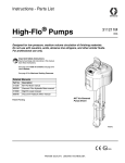
Designed for low pressure, medium volume circulation of finishing materials.
For professional use only.
Important Safety Instructions
Read all warnings and instructions in your High-Flo
Pump manual 311211. Save these instructions.
See page 2 for Table of Contents and page 2 for
List of Models and Maximum Working Pressures.
Patent Pending
TI8732a
TI8733a
Models
Contents
Models . . . . . . . . . . . . . . . . . . . . . . . . . . . . . . . . . . . 2
750cc Lowers . . . . . . . . . . . . . . . . . . . . . . . . 2
1000cc Lowers . . . . . . . . . . . . . . . . . . . . . . . 2
1500cc Lowers . . . . . . . . . . . . . . . . . . . . . . . 3
2000cc Lowers . . . . . . . . . . . . . . . . . . . . . . . 3
Warnings . . . . . . . . . . . . . . . . . . . . . . . . . . . . . . . . . 4
Repair . . . . . . . . . . . . . . . . . . . . . . . . . . . . . . . . . . . . 6
Grounding . . . . . . . . . . . . . . . . . . . . . . . . . . . . . . 6
Pressure Relief Procedure . . . . . . . . . . . . . . . . . 6
Disconnect the Lower . . . . . . . . . . . . . . . . . . . . . 7
Reconnect the Lower . . . . . . . . . . . . . . . . . . . . . 7
Reassemble the Coupling Rod and Tie Rods
to the Motor . . . . . . . . . . . . . . . . . . . . . . . . . 8
Replace the Throat Packings Without
Disconnecting the Lower . . . . . . . . . . . . . . . 8
Repair Kits . . . . . . . . . . . . . . . . . . . . . . . . . . . . . 9
Lower Disassembly . . . . . . . . . . . . . . . . . . . . . . . 9
Clean and Inspect Parts . . . . . . . . . . . . . . . . . . 10
Lower Reassembly . . . . . . . . . . . . . . . . . . . . . . 10
Lower Parts . . . . . . . . . . . . . . . . . . . . . . . . . . . . . . 14
Pump Seal Kits . . . . . . . . . . . . . . . . . . . . . . . . . . . . 20
Pump Seal Repair Kit 289548 . . . . . . . . . . . 20
Pump PTFE Seal Conversion Kit 289549 . . 20
Pump Seal Repair Kit 277360 . . . . . . . . . . . 20
Pump PTFE Seal Conversion Kit 277361 . . 20
Pump Seal Repair Kit 277362 . . . . . . . . . . . 20
Pump PTFE Seal Conversion Kit 277363 . . 20
Pump Seal Repair Kit 277358 . . . . . . . . . . . 20
Pump PTFE Seal Conversion Kit 277359 . . 20
Throat Packing Kits . . . . . . . . . . . . . . . . . . . . . . . . 21
Throat Packing Kit 239868 . . . . . . . . . . . . . 21
Throat Packing Kit 239872 . . . . . . . . . . . . . 21
Throat Packing Kit 239866 . . . . . . . . . . . . . 21
Throat Packing Kit 277356 . . . . . . . . . . . . . 21
Throat Packing Kit 277357 . . . . . . . . . . . . . 21
Throat Packing Kit 24C405 . . . . . . . . . . . . . 21
Graco Standard Warranty . . . . . . . . . . . . . . . . . . . 22
Graco Information . . . . . . . . . . . . . . . . . . . . . . . . . 22
Models
750cc Lowers
Model
No.
289366
Series Material
A
SST
Seat
Tungsten
Carbide
Size
(cc)
Maximum Pump
Working Pressure
psi (MPa, bar)
Rod/Cylinder
Material
Connection Style
Parts
Page
750
500 (3.4, 34)
Chromex/Chrome
Inlet/Outlet 1-1/2 in. tri-clamp
15
Size
(cc)
Maximum Pump
Working Pressure
psi (MPa, bar)
Rod/Cylinder
Material
Connection Style
Parts
Page
400 (2.8, 28)
Chromex/Chrome
400 (2.8, 28)
Chromex/Chrome
1000
400 (2.8, 28)
Chromex/Nitride
1000
400 (2.8, 28)
Chromex/MaxLife
1000
400 (2.8, 28)
Chromex/Chrome
1000
400 (2.8, 28)
1000
1000
1000cc Lowers
Model
No.
Series Material
253033
A
SST
24E783
A
SST
253061
A
CST
253398
A
SST
253423
A
SST
253520
A
SST
253523
A
SST
253568
A
SST
2
Seat
Tungsten 1000
Carbide
SST
1000
Tungsten
Carbide
Tungsten
Carbide
Tungsten
Carbide
Tungsten
Carbide
Tungsten
Carbide
Tungsten
Carbide
Chromex/Chrome
Inlet: 1-1/2 in. npt
Outlet: 1 in. npt
Inlet: 1-1/2 in. npt
Outlet: 1 in. npt
Inlet: 1-1/2 in. npt
Outlet: 1 in. npt
Inlet: 1-1/2 in. bspp
Outlet: 1-1/4 in. bspp
Inlet: 1-1/2 in. bspp
Outlet: 1-1/4 in. bspp
Inlet/Outlet 1-1/2 in. tri-clamp
16
16
400 (2.8, 28)
Chromex/MaxLife
Inlet/Outlet 1-1/2 in. tri-clamp
16
400 (2.8, 28)
Chromex/MaxLife
Inlet: 1-1/2 in. npt
Outlet: 1 in. npt
16
16
16
16
16
311690M
Models
1500cc Lowers
Model
No.
Series Material
253034
A
SST
24E784
A
SST
253062
A
CST
253085
A
SST
253397
A
SST
253521
A
SST
253524
A
SST
253569
A
SST
Seat
Maximum Pump
Working Pressure
psi (MPa, bar)
Rod/Cylinder
Material
460 (3.2, 32)
Chromex/Chrome
460 (3.2, 32)
Chromex/Chrome
1500
460 (3.2, 32)
Chromex/Nitride
1500
460 (3.2, 32)
Chromex/Chrome
1500
460 (3.2, 32)
Chromex/MaxLife
1500
460 (3.2, 32)
Chromex/Chrome
Inlet: 1-1/2 in. npt
Outlet: 1 in. npt
Inlet: 1-1/2 in. npt
Outlet: 1 in. npt
Inlet: 1-1/2 in. npt
Outlet: 1 in. npt
Inlet: 1-1/2 in. bspp
Outlet: 1-1/4 in. bspp
Inlet: 1-1/2 in. bspp
Outlet: 1-1/4 in. bspp
Inlet/Outlet 1-1/2 in. tri-clamp
1500
460 (3.2, 32)
Chromex/MaxLife
Inlet/Outlet 1-1/2 in. tri-clamp
17
1500
460 (3.2, 32)
Chromex/MaxLife
Inlet: 1-1/2 in. npt
Outlet: 1 in. npt
17
Size
(cc)
Maximum Pump
Working Pressure
psi (MPa, bar)
Rod/Cylinder
Material
460 (3.2, 32)
Chromex/Chrome
460 (3.2, 32)
Chromex/Chrome
2000
460 (3.2, 32)
Chromex/Chrome
2000
460 (3.2, 32)
Chromex/Chrome
2000
460 (3.2, 32)
Chromex/MaxLife
2000
460 (3.2, 32)
Chromex/Chrome
Inlet: 1-1/2 in. npt
Outlet: 1 in. npt
Inlet: 1-1/2 in. npt
Outlet: 1 in. npt
Inlet: 1-1/2 in. npt
Outlet: 1 in. npt
Inlet: 1-1/2 in. bspp
Outlet: 1-1/4 in. bspp
Inlet: 1-1/2 in. bspp
Outlet: 1-1/4 in. bspp
Inlet/Outlet 1-1/2 in. tri-clamp
2000
460 (3.2, 32)
Chromex/MaxLife
Inlet/Outlet 1-1/2 in. tri-clamp
18
2000
460 (3.2, 32)
Chromex/MaxLife
Inlet: 1-1/2 in. npt
Outlet: 1 in. npt
18
Size
(cc)
Tungsten 1500
Carbide
SST
1500
Tungsten
Carbide
Tungsten
Carbide
Tungsten
Carbide
Tungsten
Carbide
Tungsten
Carbide
Tungsten
Carbide
Connection Style
Parts
Page
17
17
17
17
17
17
2000cc Lowers
Model
No.
Series Material
253035
A
SST
24E785
A
SST
253063
A
SST
253086
A
SST
253396
A
SST
253522
A
SST
253525
A
SST
253570
A
SST
Wetted Parts:
311690M
Seat
Tungsten 2000
Carbide
SST
2000
Tungsten
Carbide
Tungsten
Carbide
Tungsten
Carbide
Tungsten
Carbide
Tungsten
Carbide
Tungsten
Carbide
Connection Style
Parts
Page
18
18
18
18
18
18
Carbon Steel, Stainless Steel, Leather, PTFE,
Ultra High Molecular Weight Polyethylene (UHMWPE),
Tungsten Carbide
3
Warnings
Warnings
The following warnings are for the setup, use, grounding, maintenance, and repair of this equipment. The exclamation point symbol alerts you to a general warning and the hazard symbol refers to procedure-specific risk. Refer back
to these warnings. Additional, product-specific warnings may be found throughout the body of this manual where
applicable.
WARNING
FIRE AND EXPLOSION HAZARD
Flammable fumes, such as solvent and paint fumes, in work area can ignite or explode. To help prevent
fire and explosion:
• Use equipment only in well ventilated area.
• Eliminate all ignition sources; such as pilot lights, cigarettes, portable electric lamps, and plastic drop
cloths (potential static arc).
• Keep work area free of debris, including solvent, rags and gasoline.
• Do not plug or unplug power cords, or turn power or light switches on or off when flammable fumes
are present.
• Ground all equipment in the work area. See Grounding instructions.
• Use only grounded hoses.
• Hold gun firmly to side of grounded pail when triggering into pail.
• If there is static sparking or you feel a shock, stop operation immediately. Do not use equipment
until you identify and correct the problem.
• Keep a working fire extinguisher in the work area.
PRESSURIZED EQUIPMENT HAZARD
Fluid from the gun/dispense valve, leaks, or ruptured components can splash in the eyes or on skin and
cause serious injury.
• Follow Pressure Relief Procedure in this manual, when you stop spraying and before cleaning,
checking, or servicing equipment.
• Tighten all fluid connections before operating the equipment.
• Check hoses, tubes, and couplings daily. Replace worn or damaged parts immediately.
EQUIPMENT MISUSE HAZARD
Misuse can cause death or serious injury.
• Do not operate the unit when fatigued or under the influence of drugs or alcohol.
• Do not exceed the maximum working pressure or temperature rating of the lowest rated system
component. See Technical Data in all equipment manuals.
• Use fluids and solvents that are compatible with equipment wetted parts. See Technical Data in all
equipment manuals. Read fluid and solvent manufacturer’s warnings. For complete information
about your material, request MSDS forms from distributor or retailer.
• Check equipment daily. Repair or replace worn or damaged parts immediately with genuine manufacturer’s replacement parts only.
• Do not alter or modify equipment.
• Use equipment only for its intended purpose. Call your distributor for information.
• Route hoses and cables away from traffic areas, sharp edges, moving parts, and hot surfaces.
• Do not kink or over bend hoses or use hoses to pull equipment.
• Keep children and animals away from work area.
• Comply with all applicable safety regulations.
4
311690M
Warnings
WARNING
MOVING PARTS HAZARD
Moving parts can pinch or amputate fingers and other body parts.
• Keep clear of moving parts.
• Do not operate equipment with protective guards or covers removed.
• Pressurized equipment can start without warning. Before checking, moving, or servicing equipment,
follow the Pressure Relief Procedure in this manual. Disconnect power or air supply.
TOXIC FLUID OR FUMES HAZARD
Toxic fluids or fumes can cause serious injury or death if splashed in the eyes or on skin, inhaled, or
swallowed.
• Read MSDS’s to know the specific hazards of the fluids you are using.
• Store hazardous fluid in approved containers, and dispose of it according to applicable guidelines.
• Always wear impervious gloves when spraying or cleaning equipment.
PERSONAL PROTECTIVE EQUIPMENT
You must wear appropriate protective equipment when operating, servicing, or when in the operating
area of the equipment to help protect you from serious injury, including eye injury, inhalation of toxic
fumes, burns, and hearing loss. This equipment includes but is not limited to:
• Protective eyewear
• Clothing and respirator as recommended by the fluid and solvent manufacturer
• Gloves
• Hearing protection
311690M
5
Repair
Repair
•
To service the pump assembly, see manual
311211.
•
To service the air motor, see manual 311238.
•
To service the hydraulic motor, see manual
308330.
Hydraulic power supply: follow manufacturer’s recommendations.
Surge tank: use a ground wire and clamp.
Spray gun: ground through a connection to a properly
grounded fluid hose and pump.
Fluid supply container: follow local code.
Grounding
Object being sprayed: follow local code.
The equipment must be grounded. Grounding reduces
the risk of static and electric shock by providing an
escape wire for the electrical current due to static build
up or in the event of a short circuit.
Pump: Use the ground screw (Z) and lockwasher on the
motor to attach ground wire 244524 (Y). Tighten the
screw securely. Connect the other end of the ground
wire to a true earth ground. See FIG. 1.
Solvent pails used when flushing: follow local code.
Use only conductive metal pails, placed on a grounded
surface. Do not place the pail on a nonconductive surface, such as paper or cardboard, which interrupts
grounding continuity.
To maintain grounding continuity when flushing or
relieving pressure: hold metal part of the spray gun
firmly to the side of a grounded metal pail, then trigger
the gun.
Pressure Relief Procedure
1. Engage trigger lock.
2. Air-Powered Pumps only: Close the bleed-type
master air valve.
Z
Hydraulic-Powered Pumps only: Close the hydraulic
supply line valve first, then the return line valve.
Y
TI8250a
FIG. 1
Air and fluid hoses: use only electrically conductive
hoses with a maximum of 500 ft. (150 m) combined
hose length to ensure grounding continuity. Check the
electrical resistance of hoses. If total resistance to
ground exceeds 29 megohms, replace hose immediately.
Air compressor: follow manufacturer’s recommendations.
6
3. Disengage the trigger lock.
4. Hold a metal part of the gun firmly to a grounded
metal pail. Trigger the gun to relieve pressure.
5. Engage the trigger lock.
6. Open all fluid drain valves in the system, having a
waste container ready to catch drainage. Leave
drain valve(s) open until you are ready to spray
again.
7. If you suspect the spray tip or hose is clogged or
that pressure has not been fully relieved after following the steps above, VERY SLOWLY loosen tip
311690M
Repair
guard retaining nut or hose end coupling to relieve
pressure gradually, then loosen completely. Clear
hose or tip obstruction.
3. Insert the collars (G) into the coupling nut (K).
Tighten the coupling nut onto the piston rod (H) and
torque to 90-100 ft-lb (122-135 N•m).
CAUTION
Hydraulic-Powered Pumps only: When shutting down
the hydraulic system, always shut off the hydraulic
supply line shutoff valve first, and then the return line
shutoff valve to prevent overpressurizing the motor or
its seals. When starting the hydraulic system, open
the return line shutoff valve first.
4. Flush and test the pump before reinstalling it in the
system. Connect hoses and flush the pump. While it
is pressurized, check for smooth operation and
leaks. Adjust or repair as necessary before reinstalling in the system. Reconnect the pump ground wire
before operating.
NXT Pump
Shown
Disconnect the Lower
E
To disconnect the lower, follow the procedure on this
page. See pages 8-11 for procedures to repair lower. To
disconnect pump from an electric circulation assembly,
EPXXXX, see manual 311594.
F
In stand or wall-mounted installations, you do not
have to remove the entire pump from its mounting.
2
1
1. Relieve the pressure, see Pressure Relief Procedure page 6.
C
G
K
H
Torque to 90-100 ft-lb
(122-135 N•m).
2
Torque to 50-60 ft-lb
(68-81 N•m).
3
Apply anti-seize
lubricant.
3
2
3
1
D
B
2. Disconnect the hoses from the lower and plug the
ends to prevent fluid contamination.
3. Loosen the coupling nut (K) and remove the collars
(G). Remove the coupling nut from the piston rod
(H). Unscrew the locknuts (B) from the tie rods (C).
Pull the lower (D) off the motor (E). See FIG. 2 and
FIG. 3.
TI8394a
FIG. 2
Reconnect the Lower
If the coupling rod (F) and tie rods (C) have been
disassembled from the motor, see Reassemble the
Coupling Rod and Tie Rods to the Motor on page 8.
1. Assemble the coupling nut (K) to the piston rod (H).
2. Orient the lower (D) to the motor (E). Position the
lower on the tie rods (C). Lubricate the threads of
the tie rods. Screw the tie rod locknuts (B) onto the
tie rods. Tighten the locknuts and torque to 50-55
ft-lb (68-75 N•m).
311690M
7
Repair
5. Insert the collars (G) and screw the coupling nut (K)
onto the coupling rod (F) and torque to 90-100 ft-lb
(122-135 N•m).
Viscount I+
Pump Shown
E
6. Torque the screws holding the adapter plate (J) to
the motor (E) to 15-17 ft-lb (20-23 N•m). Torque the
tie rod locknuts (B) to 50-55 ft-lb (68-75 N•m).
A
Replace the Throat Packings
Without Disconnecting the
Lower
J
2
C
F
G
K
H
3
3
1
2
1
Torque to 90-100 ft-lb B
(122-135 N•m).
2
Torque to 50-55 ft-lb
(68-75 N•m).
3
Apply anti-seize
lubricant.
D
To replace the throat packings as part of a complete service of the lower, see page 9.
Throat packing kits are available. See page 21 to
order. Parts supplied in the throat packing kit are
marked with a symbol, for example (19†). For the
best results, use all the parts in the kit.
1. Flush the pump, if possible.
TI7674b
FIG. 3
2. Stop the pump at the middle of its stroke.
3. Shut off the air or hydraulic supply.
Reassemble the Coupling Rod
and Tie Rods to the Motor
Use this procedure only if the coupling rod (F) and
tie rods (C) have been disassembled from the
motor, to ensure proper alignment of the motor
shaft to the piston rod.
1. Loosen, but do not remove, the screws holding the
adapter plate (J) to the motor (E) on Viscount I+
pumps. See FIG. 3.
2. Screw the tie rods (C) into the adapter plate (J) and
torque to 50-55 ft-lb (68-75 N•m). On Viscount I+
pumps, the tie rods will engage threaded holes in
the base of the motor.
3. Fill the cavity in the bottom of the motor shaft with
grease. Screw the coupling rod (F) into the motor
shaft until the pin holes align. On Viscount I+
pumps, install the pin (A) in the first hole from the
end of the coupling.
4. Align the lower (D) with the tie rods (C) and loosely
install the tie rod locknuts (B).
8
4. Unscrew the coupling nut (K) from the piston rod
(H). Allow the nut and collars (G) to rest on the piston rod. See FIG. 2.
5. Cycle the pump slowly to the bottom of its stroke.
6. Relieve the pressure, see Pressure Relief Procedure, page 6.
7. Lift the motor shaft and remove the coupling nut (K)
and collars (G). See FIG. 2 and FIG. 3.
8. Loosen the packing nut (21). See FIG. 8.
Keep packing nut installed, but loose.
9. Loosen and remove the throat cartridge (35).
Remove the PTFE o-ring (36). See FIG. 8.
10. Remove the glands (19, 26) and packings (20, 25).
311690M
Repair
11. Lubricate the throat packings and glands. Install one
male gland (19†), then five v-packings with the lips
facing down: one UHMWPE (20†), one leather
(25†), UHMWPE, leather, UHMWPE. Install the
female gland (26†). Install three v-packings with the
lips facing up: UHMWPE, leather, UHMWPE. Install
the other male gland (19†). Install the packing nut
(21) finger-tight. See FIG. 8.
Inspect the surface of the piston rod (17). If it is
scratched, replace the piston rod.
4. Remove the four capscrews (9) and washers (8)
from around the outlet manifold (22).
5. Remove the outlet manifold (22), balls (23), seats
(24), and gaskets (7).
6. Remove the three cylinder bolts (13) and lockwashers (14). Lift off the outlet housing (16), along with
the fluid tubes (3), cylinder (1), and piston assembly
(17, 10, 11, 12, 39).
7. Remove the throat cartridge (35) and o-ring (36).
8. Remove the glands (19, 26) and packings (20, 25).
12. Install the o-ring (36†) on the throat cartridge (35).
Apply lubricant to the throat cartridge threads then
screw the cartridge into the upper pump housing
(1). Torque the throat cartridge to 100 ft-lb (135
N•m).
9. Remove the tubes (3) and cylinder (1) from the inlet
housing (15). Pull the piston assembly out of the cylinder.
10. Remove the inlet manifold (18) from the vise.
13. Tighten the packing nut (21) firmly and then turn the
nut another 1/4 turn. If you have a torque wrench,
tighten the packing nut to 30 ft-lb (40 N•m), then
re-tighten to 15-20 ft-lb (20-27 N•m).
14. Screw the coupling nut (K) and collars (G) onto the
piston rod (H). Torque to 145-150 ft-lb (197-203
N•m). See FIG. 2.
15. On Viscount I+ pumps, reinstall the pin (A). If necessary, reconnect the hydraulic supply and move the
pump to the middle of its stroke. Install the pin in the
first hole from the end of the coupling.
Repair Kits
Pump seal kits are available for each pump size. Throat
packing kits are also available. See page 19 to order.
11. Remove the four capscrews (9) and washers (8)
from the inlet manifold (18). Use a flatblade screwdriver inserted between the inlet housing (15) and
the inlet manifold (18) to separate them.
One intake seat (6) includes a pressure relief valve
(V). This seat must be located exactly where shown
(the left side as viewed in FIG. 7). Use the text cast
into the inlet housing as a guide.
12. Remove the balls (5), intake seats (6 and 34), and
gaskets (7).
13. Inspect the pressure relief valve in the seat (6) to
make sure it is not clogged. Press down on the
valve's ball to see if the ball and the spring are free
to move. See FIG. 4.
Parts supplied in the pump seal kit are marked with one
asterisk in the text and drawings, for example (2*). Parts
supplied in the throat packing kit are marked with a symbol, for example (19†). For the best results, use all the
parts in the kit.
pin
Lower Disassembly
7
1. Remove the pump from the motor as described on
page 6. See also FIG. 7.
ball
spring
2. Secure the inlet manifold (18) in a vise.
pressure
relief
valve
3. Loosen, but do not remove, the packing nut (21) and
cartridge (35). See FIG. 7.
6
TI8407a
FIG. 4
311690M
9
Repair
CAUTION
If the pressure relief valve in the seat (6) is clogged or
filled with material, soak the seat in a compatible solvent. Make sure all material residue is cleaned from
the ball and seat area.
the positioning of the seat, ensuring that the vent
hole (V) is not blocked by part of the housing. See
FIG. 5.
P
If the relief valve cannot be thoroughly cleaned so that
the ball and spring are free to move, replace the seat
(6).
7
14. Place the flats of the piston nut (12) in a vise.
Unscrew the rod (17) from the nut and spacer. Disassemble the piston (10) and remove the seal (11).
ball
spring
Clean and Inspect Parts
Clean all parts in a compatible solvent. Inspect all parts
for wear or damage. If you are using a repair kit, use all
the new parts in the kit, discarding the old ones they
replace. Replace any other parts as needed. Worn or
damaged parts may cause the pump to perform poorly
or cause premature wear of the new seals and packings.
Lower Reassembly
1. Place the halves of the piston (10) around the packing (11) and snap them together. See FIG. 8.
2. Apply thread sealant (Loctite® 263 or 2760) to the
piston rod (17) threads. Screw the rod through the
piston, packing, and spacer and into the piston nut
(12). Torque the nut to 95-100 ft-lb (129-135 N•m).
Allow to cure for at least 12 hours before use.
3. With the lower pump housing (11) turned upside
down, install the balls (5) and the gaskets (7*).
COMPONENT RUPTURE HAZARD
The relief valve seat (6) must be installed at the fluid
intake, as shown in FIG. 8. The relief valve reduces the
risk of pump overpressurization. The seat cannot
relieve pressure if installed on the other side of the inlet
housing.
pressure
relief
valve
6
TI8407a
FIG. 5
5. Install the inlet seat without a relief valve (34) in the
right side of the inlet housing (15).
The seats (6 and 34) are not reversible; the chamfered side must face the ball.
6. Place the inlet manifold (18) on the inlet housing
(15). Install the lockwashers (8) and capscrews (9).
Torque to 25-30 ft-lb (34-40 N•m). See FIG. 8.
7. Place the intake manifold (18) in a vise. Place one
o-ring (2*) in each side of the inlet housing (15),
where the tubes (3) sit. Place o-rings (2*) in the
grooves at each end of the tubes. Place a gasket (4)
in both the inlet and outlet housing (15 and 16).
Position the tubes and cylinder (1) in the lower
housing.
It may be necessary to use a rubber mallet to set
the fluid tubes (3) and cylinder (4) in place.
4. Install the relief valve intake seat (6) in the left side
of the lower housing (11), as viewed in FIG. 8. (Text
cast into the lower housing identifies the correct
location for the relief valve seat.) The pin (P) on the
seat must point up into the housing. The pin limits
10
311690M
Repair
8. Lubricate the inside of the cylinder (4). Slide the piston assembly into the cylinder. Rotate the piston as
shown in FIG. 6.
washers (8) and screws (9), and torque to 25-30
ft-lb (34-40 N•m).
Seat (24) is reversible.
15. Reconnect the lower to the motor. See page 7.
TI8734a
FIG. 6
9. Install the o-ring (39†) on the throat cartridge (35),
then screw the throat cartridge into the outlet housing (16).
10. Lubricate the throat packings and glands. Install one
male gland (19†), then five v-packings with the lips
facing down: one UHMWPE (20†), one leather
(25†), UHMWPE, leather, UHMWPE. Install the
female gland (26†). Install three v-packings with the
lips facing up: UHMWPE, leather, UHMWPE. Install
the other male gland (19†). Install the packing nut
(21) finger-tight.
11. Install the outlet housing (16). It may not seat well
on the tubes and cylinder. Install the bolts and lockwashers (14) from the inlet housing (15). As you
tighten the bolts into the outlet housing (16), they
will draw the housings firmly onto the tubes and cylinders. Tighten the bolts uniformly and torque to
25-30 ft-lb (34-40 N•m).
12. Apply lubricant to the throat cartridge threads and
torque the cartridge (35) to 100 ft-lb (135 N•m).
13. Tighten the packing nut (21) firmly and then turn the
nut another 1/4 turn. If you have a torque wrench,
tighten the packing nut to 30 ft-lb (40 N•m), then
re-tighten to 15-20 ft-lb (20-27 N•m).
14. Place a ball (23), seat (24) and gasket (7*) in each
side of the outlet manifold (22). Install the outlet
manifold on the outlet housing (16). Install the lock-
311690M
11
Repair
21
8
7
19
17
20
25
20
10
26
20
25
20
25
20
5
2
9
19
8
22
35
3
6
1
11
10
39
6
7
36
16
23
12
24
7
15
2
4
14
3
15
1
7
7
5
5
2
6
34
4
18
1
Apply lubricant to all packings.
2
Apply Loctite 243 (blue) to threads. Allow to
cure for at least 12 hours before use.
3
Apply Loctite 263 or 2760 (red) to threads.
Allow to cure for at least 12 hours before use.
4
Tighten uniformly until cylinder (4) is seated.
Torque to 25-30 ft-lb (34-40 N•m).
5
Torque 25-30 ft-lb (34-40 N•m).
6
Torque 95-100 ft-lb (129-135 N•m).
7
Apply thread lubricant.
8
Torque to 30 ft-lb (40 N•m), then back off and
retighten to 15-20 ft-lb (20-27 N•m).
13
4
8
17
5
2
9
TI7668b
FIG. 7
12
311690M
Repair
OUTLET
22
21
23
16
19
20
25
20
26
20
25
20
25
20
24
36
7
17
2
19
35
4
10
36
3
11
TI7668a-1
39
12
1
13
15
2
14
13
5
5
6
34
7
7
18
TI7666a
INLET
FIG. 8
311690M
13
Lower Parts
Lower Parts
750cc Lower parts list, see page 15
1000cc Lower parts list, see page 16
1500cc Lower parts list, see page 17
2000cc Lower parts list, see page 18
21
8
7
19
17
20
25
20
10
26
20
25
20
25
20
5
2
9
19
8
22
35
3
6
1
11
10
39
6
7
36
16
23
12
24
7
15
2
4
14
3
15
1
4
2
1
Apply lubricant to all packings.
2
Apply Loctite 243 (blue) to threads. Allow to
cure for at least 12 hours before use.
3
Apply Loctite 263 or 2760 (red) to threads.
Allow to cure for at least 12 hours before use.
4
Tighten uniformly until cylinder (4) is seated.
Torque to 25-30 ft-lb (34-40 N•m).
5
Torque 25-30 ft-lb (34-40 N•m).
6
Torque 95-100 ft-lb (129-135 N•m).
7
Apply thread lubricant.
8
Torque to 30 ft-lb (40 N•m), then back off and
retighten to 15-20 ft-lb (20-27 N•m).
14
7
7
5
5
6
34
18
13
4
8
17
5
2
9
TI7668b
311690M
Lower Parts
750cc Lowers
Part No. 289366, Series A, Stainless Steel
Ref.
No.
1
2*
3
4*
5
6
7*
8
9
10
11*
12
13
14
15
16
17
18
19†
20†
21
22
23
24
25†
26†
34
35
36†
37▲
Part No.
183049
108526
183085
181875
101968
253483
181877
111003
112084
183081
181680
108528
108523
108525
181905
192512
16A462
15H663
192263
183295
181684
15H664
110259
15H746
120238
192264
239865
192490
107313
172479
Description
Qty.
CYLINDER, pump, sst
1
PACKING, o-ring; PTFE
6
TUBE, fluid; sst
2
GASKET, cylinder; UMWPE
2
BALL, intake; 1.25 in. dia; sst
2
SEAT, intake valve, with relief valve; sst
1
GASKET, seat, valve; UHMWPE
4
WASHER, flat; 8.4 mm; sst
8
CAPSCREW, hex hd; M8 x 1.25 x 25; sst
8
PISTON; 2.5 in.; sst
2
PACKING, piston; 2.5 in.; UHMWPE
1
NUT, piston; hex hd; sst
1
CAPSCREW, hex hd; 9/16-12 unc x 7.5 in.; sst
3
LOCKWASHER, spring; 9/16 in.; sst
3
HOUSING, inlet; sst
1
HOUSING, outlet; sst
1
ROD, piston; sst
1
MANIFOLD, inlet; sst
1
GLAND, male; sst
2
V-PACKING, throat; UHMWPE
5
NUT, packing; sst
1
MANIFOLD, outlet; sst
1
BALL, outlet; 1 in. (25 mm) dia.; sst
2
SEAT, valve; tungsten carbide
2
V-PACKING, throat; leather
3
GLAND, female; sst
1
SEAT, intake valve; sst
1
ADAPTER; sst
1
PACKING, o-ring; PTFE
1
TAG, warning (not shown)
1
▲ Replacement Danger and Warning labels, tags, and cards are available at no cost.
*
Parts included in Seal Repair Kit (purchase separately). See page 20.
†
Parts included in Throat Packing Repair Kit (purchase separately). See page 21.
311690M
15
Lower Parts
1000cc Lowers
Part No. 253033, Series A, Stainless Steel
Part No. 253061, Series A, Carbon Steel
Part No. 253398, Series A, Stainless Steel
Part No. 253423, Series A, Stainless Steel
Part No. 253520, Series A, Stainless Steel
Part No. 253523, Series A, Stainless Steel
Part No. 253568, Series A, Stainless Steel
Lower
Ref.
No. Description
1
CYLINDER, pump, sst
CYLINDER, pump, cst
2*
PACKING, o-ring; PTFE
3
TUBE, fluid; sst
4*
GASKET, cylinder; UMWPE
5
BALL, intake; 1.25 in. dia; sst
6
SEAT, intake valve, with relief valve; sst
7*
GASKET, seat, valve; UHMWPE
8
WASHER, flat; 8.4 mm; sst
9
CAPSCREW, hex hd; M8 x 1.25 x 25; sst
CAPSCREW, hex hd; M8 x 1.25 x 25; cst
10 PISTON; 3 in.; sst
11* PACKING, piston; 3 in.; UMWPE
12 NUT, piston; hex hd; sst
CAPSCREW, hex hd; 9/16-12 unc x 7.5 in.;
13
sst
CAPSCREW, hex hd; 9/16-12 unc x 7.5 in.;
cst
14 LOCKWASHER, spring; 9/16 in.; sst
LOCKWASHER, spring; 9/16 in.; cst
15 HOUSING, inlet; sst
HOUSING, inlet; cst
16 HOUSING, outlet; sst
HOUSING, outlet; cst
17 ROD, piston; sst
18 MANIFOLD, inlet; sst
MANIFOLD, inlet; cst
19† GLAND, male; sst
20† V-PACKING, throat; UHMWPE
21 NUT, packing; sst
22 MANIFOLD, outlet; sst
MANIFOLD, outlet; cst
23 BALL, outlet; 1 in. (25 mm) dia.; sst
24 SEAT, valve; tungsten carbide
SEAT, valve; sst
25† V-PACKING, throat; leather
26† GLAND, female; sst
34 SEAT, intake valve; sst
35 ADAPTER; sst
36† PACKING, o-ring; PTFE
37▲ TAG, warning (not shown)
39 SPACER
253033 24E783 253061 253398
183047 183047
15H452
183032
108526 108526 108526 108526
183085 183085 183085 183085
183094 183094 183094 183094
101968 101968 101968 101968
253483 253483 253483 253483
181877 181877 181877 181877
111003 111003 111003 111003
112084
112084 112084
107558
15G883 15G883 15G883 15G883
15G886 15G886 15G886 15G886
15H989 15H989 15H989 15H989
120199 120199
253423 253520 253523 253568 Qty.
183047 183047 15H452 15H452
1
1
108526 108526 108526 108526
6
183085 183085 183085 183085
2
183094 183094 183094 183094
2
101968 101968 101968 101968
2
253483 253483 253483 253483
1
181877 181877 181877 181877
4
111003 111003 111003 111003
8
112084 112084 112084 112084
8
8
15G883 15G883 15G883 15G883
2
15G886 15G886 15G886 15G886
1
15H989 15H989 15H989 15H989
1
120199 120199 120199 120199 120199
120446
108525 108525
3
108525 108525 108525 108525 108525
101333
15G770 15G770 15G770 15G770 15G770
15G770 15G770
15G891
15G771 15G771
15G771 15G771 15G771 15G771
16A462
192259
16A462 16A462 16A462 16A462
193205 15H663 15H663 192259
192263
183295
181684
15G873
110259
15H746
120238
192264
239865
192490
107313
172479
16D850
3
15G771
15G892
16A462 16A462 16A462
193205
192259
192260
192263 192263 192263
183295 183295 183295
181684 181684 181684
15G874
15G873
181728
110259 110259 110259
15H746 15H746
183095
120238 120238 120238
192264 192264 192264
239865 239865 239865
192490 192490 192490
107313 107313 107313
172479 172479 172479
16D850 16D850 16D850
192263
183295
181684
15G874
192263
183295
181684
15G664
192263
183295
181684
15H664
192263
183295
181684
15G873
110259 110259 110259 110259
15H746 15H746 15H746 15H746
120238
192264
239865
192490
107313
172479
16D850
120238
192264
236865
192490
107313
172479
16D850
120238
192264
239865
192490
107313
172479
16D850
120238
192264
239865
192490
107313
172479
16D850
3
3
1
1
1
1
1
1
1
2
5
1
1
1
2
2
2
3
1
1
1
1
1
1
▲ Replacement Danger and Warning labels, tags, and cards are available at no cost.
*
Parts included in Seal Repair Kit (purchase separately). See page 20.
†
Parts included in Throat Packing Repair Kit (purchase separately). See page 21.
16
311690M
Lower Parts
1500cc Lowers
Part No. 253034, Series A, Stainless Steel
Part No. 253062, Series A, Carbon Steel
Part No. 253085, Series A, Stainless Steel
Part No. 253397, Series A, Stainless Steel
Part No. 253521, Series A, Stainless Steel
Part No. 253524, Series A, Stainless Steel
Part No. 253569, Series A, Stainless Steel
Lower
Ref.
No. Description
1
CYLINDER, pump, sst
CYLINDER, pump, cst
2*
PACKING, o-ring; PTFE
3
TUBE, fluid; sst
4*
GASKET, cylinder; UMWPE
5
BALL, intake; 1.25 in. dia; sst
6
SEAT, intake valve, with relief valve; sst
7*
GASKET, seat, valve; UHMWPE
8
WASHER, flat; 8.4 mm; sst
9
CAPSCREW, hex hd; M8 x 1.25 x 25; sst
CAPSCREW, hex hd; M8 x 1.25 x 25; cst
10 PISTON; 3.5 in.; sst
11* PACKING, piston; 3.5 in.; UMWPE
12 NUT, piston; hex hd; sst
CAPSCREW, hex hd; 9/16-12 unc x 7.5 in.;
13
sst
CAPSCREW, hex hd; 9/16-12 unc x 7.5 in.;
cst
14 LOCKWASHER, spring; 9/16 in.; sst
LOCKWASHER, spring; 9/16 in.; cst
15 HOUSING, inlet; sst
HOUSING, inlet; cst
16 HOUSING, outlet; sst
HOUSING, outlet; cst
17 ROD, piston; sst
18 MANIFOLD, inlet; sst
MANIFOLD, inlet; cst
19† GLAND, male; sst
20† V-PACKING, throat; UHMWPE
21 NUT, packing; sst
22 MANIFOLD, outlet; sst
MANIFOLD, outlet; cst
23 BALL, outlet; 1 in. (25 mm) dia.; sst
24 SEAT, valve; tungsten carbide
SEAT, valve; sst
25† V-PACKING, throat; leather
26† GLAND, female; sst
34 SEAT, intake valve; sst
35 ADAPTER; sst
36† PACKING, o-ring; PTFE
37▲ TAG, warning (not shown)
39 SPACER
253034 24E784 253062 253085
183048 183048
183048
181900
108526 108526 108526 108526
183085 183085 183085 183085
181876 181876 181876 181876
101968 101968 101968 101968
253483 253483 253483 253483
181877 181877 181877 181877
111003 111003 111003 111003
112084
112084 112084
107558
15G884 15G884 15G884 15G884
15G887 15G887 15G887 15G887
15H989 15H989 15H989 15H989
120199 120199
253397 253521 253524 253569 Qty.
15H453 183048 15H453 15H453
1
1
108526 108526 108526 108526
6
183085 183085 183085 183085
2
181876 181876 181876 181876
2
101968 101968 101968 101968
2
253483 253483 253483 253483
1
181877 181877 181877 181877
4
111003 111003 111003 111003
8
112084 112084 112084 112084
8
8
15G884 15G884 15G884 15G884
2
15G887 15G887 15G887 15G887
1
15H989 15H989 15H989 15H989
1
120199 120199 120199 120199 120199
120446
108525 108525
3
108525 108525 108525 108525 108525
101333
15G770 15G770 15G770 15G770 15G770
15G770 15G770
15G891
15G771 15G771
15G771 15G771 15G771 15G771
16A462
192259
16A462 16A462 16A462 16A462
193205 15H663 15H663 192259
192263
183295
181684
15G873
110259
15H746
120238
192264
239865
192490
107313
172479
16D851
3
15G771
15G892
16A462 16A462 16A462
192259
192259
192260
192263 192263 192263
183295 183295 183295
181684 181684 181684
15G874
15G873
181728
110259 110259 110259
15H746 15H746
183095
120238 120238 120238
192264 192264 192264
239865 239865 239865
192490 192490 192490
107313 107313 107313
172479 172479 172479
16D851 16D851 16D851
192263
183295
181684
15G874
192263
183295
181684
15H664
192263
183295
181684
15H664
192263
183295
181684
15G873
110259 110259 110259 110259
15H746 15H746 15H746 15H746
120238
192264
239865
192490
107313
172479
16D851
120238
192264
239865
192490
107313
172479
16D851
120238
192264
239865
192490
107313
172479
16D851
120238
192264
239865
192490
107313
172479
16D851
3
3
1
1
1
1
1
1
1
2
5
1
1
1
2
2
2
3
1
1
1
1
1
1
▲ Replacement Danger and Warning labels, tags, and cards are available at no cost.
*
Parts included in Seal Repair Kit (purchase separately). See page 20.
†
Parts included in Throat Packing Repair Kit (purchase separately). See page 21.
311690M
17
Lower Parts
2000cc Lowers
Part No. 253035, Series A, Stainless Steel
Part No. 253063, Series A, Carbon Steel
Part No. 253086, Series A, Stainless Steel
Part No. 253396, Series A, Stainless Steel
Part No. 253522, Series A, Stainless Steel
Part No. 253525, Series A, Stainless Steel
Part No. 253570, Series A, Stainless Steel
Lower
Ref.
No.
1
2*
3
4*
5
6
7*
8
9
10
11*
12
13
14
15
16
17
18
19†
20†
21
22
23
24
25†
26†
34
35
36†
37▲
39
Description
CYLINDER, pump, sst
PACKING, o-ring; PTFE
TUBE, fluid; sst
GASKET, cylinder; UMWPE
BALL, intake; 1.25 in. dia; sst
SEAT, intake valve, with relief valve; sst
253035
15G882
108526
183085
15G881
101968
253483
24E785
15G882
108526
183085
15G881
101968
253483
253063
15G882
108526
183085
15G881
101968
253483
GASKET, seat, valve; UHMWPE
WASHER, flat; 8.4 mm; sst
CAPSCREW, hex hd; M8 x 1.25 x 25; sst
CAPSCREW, hex hd; M8 x 1.25 x 25; cst
PISTON; 4 in.; sst
PACKING, piston; 4 in.; UMWPE
NUT, piston; hex hd; sst
CAPSCREW, hex hd; 9/16-12 unc x 7.5 in.;
sst
CAPSCREW, hex hd; 9/16-12 unc x 7.5 in.;
cst
LOCKWASHER, spring; 9/16 in.; sst
LOCKWASHER, spring; 9/16 in.; cst
HOUSING, inlet; sst
HOUSING, inlet; cst
HOUSING, outlet; sst
HOUSING, outlet; cst
ROD, piston; sst
MANIFOLD, inlet; sst
MANIFOLD, inlet; cst
GLAND, male; sst
V-PACKING, throat; UHMWPE
NUT, packing; sst
MANIFOLD, outlet; sst
MANIFOLD, outlet; cst
BALL, outlet; 1 in. (25 mm) dia.; sst
SEAT, valve; tungsten carbide
SEAT, valve; sst
V-PACKING, throat; leather
GLAND, female; sst
SEAT, intake valve; sst
ADAPTER; sst
PACKING, o-ring; PTFE
TAG, warning (not shown)
SPACER
181877 181877 181877 181877
111003 111003 111003 111003
112084
112084 112084
107558
15G885 15G885 15G885 15G885
15G888 15G888 15G888 15G888
15H989 15H989 15H989 15H989
120199 120199
253086
15G882
108526
183085
15G881
101968
253483
253396
15H451
108526
183085
15G881
101968
253483
253522
15G882
108526
183085
15G881
101968
253483
253525
15H451
108526
183085
15G881
101968
253483
253570 Qty.
15H451
1
108526
6
183085
2
15G881
2
101968
2
253483
1
181877 181877 181877 181877
111003 111003 111003 111003
112084 112084 112084 112084
15G885 15G885 15G885 15G885
15G888 15G888 15G888 15G888
15H989 15H989 15H989 15H989
4
8
8
8
2
1
1
120199 120199 120199 120199 120199
3
120446
108525 108525
3
108525 108525 108525 108525 108525
101333
15G770 15G770 15G770 15G770 15G770
15G770 15G770
15G891
15G771 15G771
15G771 15G771 15G771 15G771
16A462
192259
16A462 16A462 16A462 16A462
193205 15H663 15H663 192259
192263
183295
181684
15G873
110259
15H746
120238
192264
239865
192490
107313
172479
16D852
15G771
15G892
16A462 16A462 16A462
193205
192259
192260
192263 192263 192263
183295 183295 183295
181684 181684 181684
15G874
15G873
181728
110259 110259 110259
15H746 15H746
183095
120238 120238 120238
192264 192264 192264
239865 239865 239865
192490 192490 192490
107313 107313 107313
172479 172479 172479
16D852 16D852 16D852
192263
183295
181684
15G874
192263
183295
181684
15H664
192263
183295
181684
15H664
192263
183295
181684
15G873
110259 110259 110259 110259
15H746 15H746 15H746 15H746
120238
192264
239865
192490
107313
172479
16D852
120238
192264
239865
192490
107313
172479
16D852
120238
192264
239865
192490
107313
172479
16D852
120238
192264
239865
192490
107313
172479
16D852
3
3
1
1
1
1
1
1
1
2
5
1
1
1
2
2
2
3
1
1
1
1
1
1
▲ Replacement Danger and Warning labels, tags, and cards are available at no cost.
*
Parts included in Seal Repair Kit (purchase separately). See page 20.
†
Parts included in Throat Packing Repair Kit (purchase separately). See page 21.
18
311690M
Lower Parts
311690M
19
Pump Seal Kits
Pump Seal Kits
Pump Seal Repair Kit 289548
Pump PTFE Seal Conversion Kit 289549
Pump Seal Repair Kit 277362
Pump PTFE Seal Conversion Kit 277363
Lower Model 289366
Lower Models: 253034, 253062, 253085, 253397,
253521, 253524, 253569
Part No.
Description
181877
108526
181875
181680
GASKET, seat, valve
PACKING, o-ring
SEAL, gasket, cylinder
PACKING, piston, 2.5 in., UHMWPE
(Kit 289548)
PACKING, piston, 2.5 in., PTFE
(Kit 289549)
187761
Qty.
4
6
2
1
Description
GASKET, seat, valve
PACKING, o-ring
GASKET, cylinder
PACKING, piston, 3 in., UHMWPE
(Kit 277360)
PACKING, piston, 3 in., PTFE
(Kit 277361)
15H467
20
GASKET, seat, valve
PACKING, o-ring
GASKET, cylinder
PACKING, piston, 3.5 in., UHMWPE
(Kit 277362)
PACKING, piston, 3.5 in., PTFE
(Kit 277363)
15H468
Qty.
4
6
2
1
1
Pump Seal Repair Kit 277358
Pump PTFE Seal Conversion Kit 277359
Lower Models: 253033, 253061, 253398, 253423,
253520, 253523, 253568
181877
108526
183094
15G886
Description
181877
108526
181876
15G887
1
Pump Seal Repair Kit 277360
Pump PTFE Seal Conversion Kit 277361
Part No.
Part No.
Lower Models: 253035, 253063, 253086, 253396,
253522, 253525, 253570
Qty.
4
6
2
1
Part No.
Description
181877
108526
15G881
15G888
GASKET, seat, valve
PACKING, o-ring
SEAL, gasket, cylinder
PACKING, piston, 4 in., UHMWPE
(Kit 277358)
PACKING, piston, 4 in., PTFE
(Kit 277359)
1
15H469
Qty.
4
6
2
1
1
311690M
Throat Packing Kits
Throat Packing Kits
Throat Packing Kit 239868
Throat Packing Kit 277356
With leather throat packings.
For pumps with 750cc lowers.
With leather throat packings.
For pumps with 1000cc, 1500cc and 2000cc lowers.
Part No.
192264
183294
192263
107313
Description
GLAND, female
PACKING, vee, leather
GLAND, male
PACKING, o-ring
Qty.
1
8
2
1
Part No.
192264
120238
192263
107313
Description
GLAND, female
PACKING, vee, leather
GLAND, male
PACKING, o-ring
Throat Packing Kit 239872
Throat Packing Kit 277357
With leather and UHMWPE throat packings.
For pumps with 750cc lowers.
With leather and UHMWPE throat packings.
For pumps with 1000cc, 1500cc and 2000cc lowers.
Part No.
192264
183295
183294
192263
107313
Description
GLAND, female
PACKING, vee, uhmwpe
PACKING, vee, leather
GLAND, male
PACKING, o-ring
Qty.
1
5
3
2
1
Part No.
192264
183295
120238
192263
107313
Description
GLAND, female
PACKING, vee, uhmwpe
PACKING, vee, leather
GLAND, male
PACKING, o-ring
Throat Packing Kit 239866
Throat Packing Kit 24C405
With PTFE throat packings.
For pumps with 750cc, 1000cc, 1500cc and 2000cc
lowers.
With UHMWPE and PTFE throat packings.
For pumps with 750cc, 1000cc, 1500cc and 2000cc
lowers.
Part No.
192264
183352
192263
107313
311690M
Description
GLAND, female
PACKING, vee, ptfe
GLAND, male
PACKING, o-ring
Qty.
1
8
2
1
Part No.
192264
183295
183352
192263
107313
Description
GLAND, female
PACKING, vee, uhmwpe
PACKING, vee, ptfe
GLAND, male
PACKING, o-ring
Qty.
1
8
2
1
Qty.
1
5
3
2
1
Qty.
1
5
3
2
1
21
Graco Standard Warranty
Graco warrants all equipment referenced in this document which is manufactured by Graco and bearing its name to be free from defects in
material and workmanship on the date of sale to the original purchaser for use. With the exception of any special, extended, or limited warranty
published by Graco, Graco will, for a period of twelve months from the date of sale, repair or replace any part of the equipment determined by
Graco to be defective. This warranty applies only when the equipment is installed, operated and maintained in accordance with Graco’s written
recommendations.
This warranty does not cover, and Graco shall not be liable for general wear and tear, or any malfunction, damage or wear caused by faulty
installation, misapplication, abrasion, corrosion, inadequate or improper maintenance, negligence, accident, tampering, or substitution of
non-Graco component parts. Nor shall Graco be liable for malfunction, damage or wear caused by the incompatibility of Graco equipment with
structures, accessories, equipment or materials not supplied by Graco, or the improper design, manufacture, installation, operation or
maintenance of structures, accessories, equipment or materials not supplied by Graco.
This warranty is conditioned upon the prepaid return of the equipment claimed to be defective to an authorized Graco distributor for verification of
the claimed defect. If the claimed defect is verified, Graco will repair or replace free of charge any defective parts. The equipment will be returned
to the original purchaser transportation prepaid. If inspection of the equipment does not disclose any defect in material or workmanship, repairs will
be made at a reasonable charge, which charges may include the costs of parts, labor, and transportation.
THIS WARRANTY IS EXCLUSIVE, AND IS IN LIEU OF ANY OTHER WARRANTIES, EXPRESS OR IMPLIED, INCLUDING BUT NOT LIMITED
TO WARRANTY OF MERCHANTABILITY OR WARRANTY OF FITNESS FOR A PARTICULAR PURPOSE.
Graco’s sole obligation and buyer’s sole remedy for any breach of warranty shall be as set forth above. The buyer agrees that no other remedy
(including, but not limited to, incidental or consequential damages for lost profits, lost sales, injury to person or property, or any other incidental or
consequential loss) shall be available. Any action for breach of warranty must be brought within two (2) years of the date of sale.
GRACO MAKES NO WARRANTY, AND DISCLAIMS ALL IMPLIED WARRANTIES OF MERCHANTABILITY AND FITNESS FOR A
PARTICULAR PURPOSE, IN CONNECTION WITH ACCESSORIES, EQUIPMENT, MATERIALS OR COMPONENTS SOLD BUT NOT
MANUFACTURED BY GRACO. These items sold, but not manufactured by Graco (such as electric motors, switches, hose, etc.), are subject to
the warranty, if any, of their manufacturer. Graco will provide purchaser with reasonable assistance in making any claim for breach of these
warranties.
In no event will Graco be liable for indirect, incidental, special or consequential damages resulting from Graco supplying equipment hereunder, or
the furnishing, performance, or use of any products or other goods sold hereto, whether due to a breach of contract, breach of warranty, the
negligence of Graco, or otherwise.
FOR GRACO CANADA CUSTOMERS
The Parties acknowledge that they have required that the present document, as well as all documents, notices and legal proceedings entered into,
given or instituted pursuant hereto or relating directly or indirectly hereto, be drawn up in English. Les parties reconnaissent avoir convenu que la
rédaction du présente document sera en Anglais, ainsi que tous documents, avis et procédures judiciaires exécutés, donnés ou intentés, à la suite
de ou en rapport, directement ou indirectement, avec les procédures concernées.
Graco Information
For the latest information about Graco products, visit www.graco.com.
TO PLACE AN ORDER, contact your Graco distributor or call to identify the nearest distributor.
Phone: 612-623-6921 or Toll Free: 1-800-328-0211 Fax: 612-378-3505
All written and visual data contained in this document reflects the latest product information available at the time of publication.
Graco reserves the right to make changes at any time without notice.
Original instructions. This manual contains English. MM 311690
Graco Headquarters: Minneapolis
International Offices: Belgium, China, Japan, Korea
GRACO INC. P.O. BOX 1441 MINNEAPOLIS, MN 55440-1441
Copyright 2006, Graco Inc. is registered to ISO 9001
www.graco.com
Revised 02/2011