1
Kit Instructions
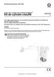
ExactaBlend™ AGP Advanced Glazing Proportioner
Heated Platen Kit
332511A
EN
For heating bulk supply of medium to high viscosity polysulfide and urethane materials.
For professional use only.
Not approved for use in explosive atmospheres or hazardous locations.
24R200
Heated platen kit, high volume
Refer to ExactaBlend AGP Advanced Glazing Proportioner, Setup-Operation manual for maximum working pressure
and model information.
Important Safety Instructions
Read all warnings and instructions in this
manual and the ExactaBlend AGP Advanced
Glazing Proportioner, Setup-Operation manual. Save all instructions.
Related Manuals
Related Manuals
Refer to ExactaBlend AGP Advanced Glazing Proportioner, Setup-Operation manual for the complete list of
related manuals.
Contents
Related Manuals . . . . . . . . . . . . . . . . . . . . . . . . . . . 2
Contents . . . . . . . . . . . . . . . . . . . . . . . . . . . . . . . . . . 2
Warnings . . . . . . . . . . . . . . . . . . . . . . . . . . . . . . . . . 3
Overview . . . . . . . . . . . . . . . . . . . . . . . . . . . . . . . . . . 3
System Description . . . . . . . . . . . . . . . . . . . . . . . 3
Power Requirements . . . . . . . . . . . . . . . . . . . . . . 3
Component Identification . . . . . . . . . . . . . . . . . . . . 4
Heated Platen Kit . . . . . . . . . . . . . . . . . . . . . . . . 4
Heat Controller . . . . . . . . . . . . . . . . . . . . . . . . . . 5
Installation . . . . . . . . . . . . . . . . . . . . . . . . . . . . . . . . 6
Grounding . . . . . . . . . . . . . . . . . . . . . . . . . . . . . . 6
Setup . . . . . . . . . . . . . . . . . . . . . . . . . . . . . . . . . . . . 13
Operation . . . . . . . . . . . . . . . . . . . . . . . . . . . . . . . . 14
Startup . . . . . . . . . . . . . . . . . . . . . . . . . . . . . . . 14
Shutdown . . . . . . . . . . . . . . . . . . . . . . . . . . . . . 14
Maintenance . . . . . . . . . . . . . . . . . . . . . . . . . . . . . . 15
Platen Maintenance . . . . . . . . . . . . . . . . . . . . . 15
Troubleshooting . . . . . . . . . . . . . . . . . . . . . . . . . . . 16
Common Problems . . . . . . . . . . . . . . . . . . . . . . 16
Repair . . . . . . . . . . . . . . . . . . . . . . . . . . . . . . . . . . . 18
Replace Platen Heaters and Sensor . . . . . . . . . 18
Schematic . . . . . . . . . . . . . . . . . . . . . . . . . . . . . . . . 19
Parts . . . . . . . . . . . . . . . . . . . . . . . . . . . . . . . . . . . . 20
Heated Platen Kit, 24R200 . . . . . . . . . . . . . . . . 20
Heat Enclosure, 24R870 . . . . . . . . . . . . . . . . . . 24
Graco Standard Warranty . . . . . . . . . . . . . . . . . . . 28
Graco Information . . . . . . . . . . . . . . . . . . . . . . . . . 28
2
332511A
Warnings
Warnings
The following warnings are for the setup, use, grounding, maintenance, and repair of this equipment. The exclamation point symbol alerts you to a general warning and the hazard symbols refer to procedure-specific risks. When
these symbols appear in the body of this manual or on warning labels, refer back to these Warnings. Product-specific
hazard symbols and warnings not covered in this section may appear throughout the body of this manual where
applicable.
WARNING
WARNING
ELECTRIC SHOCK HAZARD
This equipment must be grounded. Improper grounding, setup, or usage of the system can cause electric
shock.
• Turn off and disconnect power at main switch before disconnecting any cables and before servicing
or installing equipment.
• Connect only to grounded power source.
• All electrical wiring must be done by a qualified electrician and comply with all local codes and
regulations.
BURN HAZARD
Equipment surfaces and fluid that’s heated can become very hot during operation. To avoid severe burns:
• Do not touch hot fluid or equipment.
Overview
System Description
The heated platen kit is a field installed kit to add heat to
the platen. The additional heat may change the viscosity
properties of the material and allow the material to flow
easier through the system.
Power Requirements
A 25A (minimum) - 30A (maximum) circuit breaker must
be installed on the incoming power supply.
*
Nominal Voltage**
Wattage
Amps*
240 V
3,500 per Platen
20
Add to power requirements of ExactaBlend AGP
Advanced Glazing Proportioner system. Amps maximum per leg shown.
** 190-264 voltage range acceptable.
332511A
3
Component Identification
Component Identification
Heated Platen Kit
C
A
B
D
F
E
H
G
FIG. 1: Heated Platen Kit
Key:
A
B
C
D
E
F
4
RTD Temperature Sensor
Heater Coil
Temperature Limit Switch
Junction Box
Heat Electrical Enclosure
Main Power Switch
G
H
Heater Power Switch
Heat Controller
332511A
Component Identification
Heat Controller
AB
AC
70
12
AA
AD
90
AE
FIG. 2: Heat Controller
Key:
AA
AB
AC
AD
AE
Current Temperature
Power is Supplied to Heater
Power is Supplied to Heat Overtemp Contactor
Desired Temperature
Temperature Adjustment
332511A
5
Installation
Installation
To avoid serious injury or machine damage, all
electrical connections need to be done by a qualified
electrician in compliance with local codes.
Grounding
Ground the system as instructed within this manual.
The equipment must be grounded to reduce the risk
of static sparking and electric shock. Electric or static
sparking can cause fumes to ignite or explode.
Improper grounding can cause electric shock.
Grounding provides an escape wire for the electric
current.
1. Access the Platen
a. Perform Change Drums procedure in the
Air-Powered Ram manual. Do not load a new
drum.
b.
Perform Shutdown procedure in the ExactaBlend AGP Advanced Glazing Proportioner,
Setup-Operation manual.
c.
Thoroughly clean all material that may be found
on the top of the platen.
d. Turn off all sources of power to the machine.
6
332511A
Installation
2. Install the Heat Coils and the Thermostat Switch.
- (1) Thermostat
- (2) Washers
- (2) Screws
- (6) 1/4-20 Studs
- (6) Flat Washers
- (6) Lock Washers
- (6) Nuts
3. Connect the Ground Wires.
Connect the ground wires to the terminal lug and to the platen covers (not shown in view). Attach the conduit to the
platen cover and route the wires through the conduit when connections are complete.
- (3) Ground Wires
- (2) Lock Washers
- (2) Nuts
- (1) Terminal Lug
332511A
7
Installation
4. Connect the Power Leads.
Label “A” and “B” leads for identification in step 10. Route all the wires through the conduit when connections are
complete.
- (3) “A” Leads
- (2) “B” Leads
5. Mount the RTD.
Route the wire through the conduit when connections are complete.
- (1) RTD
- (1) Washer
- (1) M5 Screw
8
332511A
Installation
6. Attach the Platen Covers.
NOTICE
To prevent damage to wires, ensure wires are not
pinched when assembling and securing platen covers.
NOTE: Torque the platen cover fasteners to
60 +/- 10 in-lbs (6.8 +/- 1.1 N•m).
- (1) Conduit
- (1) Fastener
- (1) Fastener
- (1) Plug
- (2) Covers
332511A
9
Installation
7. Mount the Junction Box.
a. Mount the junction box to the air motor located on the 55 gallon (208 liter) ram.
b.
Route the conduit to the junction box from the platen.
- (2) #8-32 Screws
- (2) Lock Washers
- (1) 3/8-16 Bolt (Urethane)
- (1) M8 Bolt (Polysulfide)
- (1) Lock Washer
8. Mount the Heat Electrical Panel on the 5 Gallon (19 liter) Ram.
- (8) M6x16 Bolts
- (8) Washers
- (8) Lock Washers
- (8) Nuts
- (8) M6x25 Bolts
- (8) Washers
- (8) Lock Washers
- (8) Nuts
10
332511A
Installation
9. Route the Power Cord and Signal Cable to the Junction Box.
Secure the power cord and signal cable to the base (A) cross bar.
Routing
10.Connect the Leads in the Junction Box.
Connect “A” leads, “B” leads, ground, and signal cable within the junction box. Replace the cover.
332511A
11
Installation
11.Connect the Power Cable from the Heat Electrical Enclosure to
the Main Electrical Enclosure.
12.Connect Power to the Terminals and Ground.
12
332511A
Setup
Setup
1. Turn the power on at the heated platen electrical
enclosure.
2. Turn the power on at the heater power switch.
3. Set the desired platen temperature by pressing
either the up or down arrow keys.
NOTE: Temperature is displayed in Fahrenheit.
Desired Temperature
70
332511A
12
90
13
Operation
Operation
Startup
Shutdown
1. Turn the power on at the heated platen electrical
enclosure.
1. Turn the power off at the heater power switch.
2. Turn the power on at the heater power switch.
NOTE: If the entire machine is to be disconnected from
electrical power, turn the power off at the heated platen
electrical enclosure.
3. Set the desired temperature. Refer to page 5 for
details.
14
332511A
Maintenance
Maintenance
Platen Maintenance
Remove and Reinstall Platen Wipers
Refer to Supply Units Repair-Parts manual for instructions.
F
If the platen does not come out of the pail easily when
the pump is being raised, the air assist tube or check
valve may be plugged. A plugged valve prevents air from
reaching the underside of the plate to assist in raising it
from the pail.
1. Turn off main disconnect at the machine.
2. Allow equipment to cool.
C
Bleed
Stick
B
H
3. Relieve pressure and disassemble air assist valve.
Refer to Supply Systems Repair-Parts manual.
4. Clear air assist tube in platen. Clean all parts of
valve and reassemble. Refer to Supply Systems
Repair-Parts manual.
5. Remove bleed stick from platen. Push bleed stick
through bleed relieve port (P) to remove material
residue. See FIG. 3.
P
FIG. 3: Remove Platen Covers and Heaters
6. Remove platen covers. See FIG. 3.
a. Remove platen cover fasteners (F).
b.
Remove both platen covers (C) and ground wire
from platen.
7. Remove any excess fluid. Use a soft wire brush on
heater coils (H). See FIG. 3.
8. Inspect platen heater blocks (B) or heater (H) for
burn or melt spots. Replace platen heater if necessary. See FIG. 3.
9. Check for loose connections and damaged wires.
10. Follow steps in reverse order to reassemble platen.
NOTE: Torque platen cover fasteners (F) to 60 +/- 10
in-lbs (6.8 +/- 1.1 N•m) for 55 gallon platen.
332511A
15
Troubleshooting
Troubleshooting
Before performing any troubleshooting procedure:
1. Perform Pressure Relief Procedure In the ExactaBlend AGP Advanced Glazing Proportioner,
Setup-Operation manual.
2. Turn off main disconnect at the machine.
3. Allow equipment to cool.
Try the recommended solutions in the order given for
each problem, to avoid unnecessary repairs. Also,
determine that all circuit breakers, switches, and controls are properly set and wiring is correct before assuming there is a problem.
Common Problems
Problem
Heating is slow.
Cause
Low power.
Verification
Solution
Measure voltage across cir- 1. If voltage is lower than
expected, use electrical
cuit breakers. Voltage
schematic to locate
should measure between
faulty wiring or connec190 and 264 Vac.
tion.
2. Have a qualified electrician service electrical
components.
Heating over shoots.
16
Defective solid state relay.
Verify for given zone that
temperature does not
increase when zone is disabled.
Verify RTD wire or heater
power cord is attached to
correct heat module.
Replace relay.
332511A
Troubleshooting
Problem
No heat.
Cause
Verification
Solution
Tripped circuit breaker.
Visually check circuit
Determine cause of tripped
breaker for a tripped condi- circuit breaker. Then repair
tion.
fault and reset main circuit
breaker.
Low power.
Measure voltage across cir- 1. If voltage is lower than
expected, use electrical
cuit breakers. Voltage
schematic to locate
should measure between
faulty wiring or connec190 and 264 Vac.
tion.
2. Have a qualified electrician service electrical
components.
Cable unplugged/loose
wire.
Check for loose or disconnected wires and plugs.
Attach plug/wire.
Incorrect temperature set
point.
Verify zone has a correct
temperature setting on the
controller.
Enter Setup and enter correct temperature.
Contactor not closing.
Turn on heat for zone A1
and ensure contactor
closes.
1. Verify that there are no
other error conditions
that would prevent
heater from starting.
2. Replace contactor.
332511A
17
Repair
Repair
Replace Platen Heaters and
Sensor
c.
Disconnect four platen heater wires (labeled A
and B) and RTD sensor (R) connector in the terminal box.
d. Remove screws and washers. Remove platen
heater blocks (B) and RTD sensor (R).
55 Gallon Platen Heater and Sensor
6. Install new platen heaters and RTD sensor (R).
Secure RTD sensor (R) with screw and washer.
Secure platen heater blocks with nuts and washers.
1. Turn off main disconnect at the machine.
2. Allow equipment to cool.
7. Label platen heater wires A and B. Reroute platen
heater wires and platen RTD sensor (R) through the
conduit to the junction box. Reconnect the four wires
to the appropriate terminal block A and B. Reconnect the platen RTD sensor (R).
3. Remove both platen cover fasteners (F).
4. Remove both platen covers (C) and ground wire
from platen.
F
8. Reinstall junction box cover. Secure with screws and
tighten strain relief nut.
C
9. Reconnect ground wire, and install platen covers.
Secure platen covers with fasteners. Torque platen
cover fasteners to 60 in-lbs +/- 10 in-lbs (6.8 +/1.1 N•m).
B
N
L
W
R
FIG. 4: Replace Platen Heaters and RTD sensor (R)
5. Remove platen heater blocks (B).
a. Use a hex wrench to remove three nuts (N) and
washers (L, W) from each heater block.
b.
18
Remove screws from junction box cover.
Loosen strain relief nut, and remove junction
box cover.
332511A
100
101
102
103
104
105
106
107
108
109
110
111
112
113
114
115
116
117
118
119
120
121
122
123
124
125
126
127
128
129
130
131
132
133
134
135
136
137
138
139
140
141
142
143
144
145
146
147
148
149
1
1L1
1L1
L1
1L1
GND
HARNESS
16U358
HARNESS
16U358
CB
CB
20A
1120
1100
HARNESS
16U345
CB
5A
CB
HARNESS
16U353
1
1380
1360
CRM
C1
OX
ON
HARNESS
16U354
T1
T3
T2
CON120
L3
L2
L1
HARNESS
16U354
SW-1
POWER
C2
OFF
1180
HARNESS
16U345
LABEL WITH WIRE NUMBERS MARKED AS SHOWN
SEE XXXXXX FOR LABELS
1L2
1L2
220V/
1PH/
50-60HZ
L2
1L2
332511A
DISC100
CUSTOMER MUST SUPPLY BRANCH CIRCUIT PROTECTION
1361
1381
T1
SSR130
L1
BRN
1280
A2
1382
SSR130
A1
1300
BLU
HARNESS
16U356
8
7
6
5
4
3
TC-1
HARNESS
16U356
SIGNAL
+24VDC
HARNESS
16A522
2
1
255733
255733
1390
GND
1370
HARNESS
16U365
1
2
3
4
GND
GND
1
2
3
4
HARNESS
16A574
HARNESS
16A574
1391
GND
1371
SIGNAL
EXC
24E265
B
HARNESS
16A356
A
1392
THERM SW
15B137
HARNESS
(16D383)
R-1
RTD
16D383
GND
A
B
1392
1371
1371
Schematic
Schematic
19
Parts
Parts
Heated Platen Kit, 24R200
2
2
6
5,
26
3
5
11
22
23
28
11
14
7
14
FIG. 5: Heated Platen Kit
20
332511A
Parts
32
30
19
33
34
16,
45
25
36
35
4
21
18
27
17
8
24
8
10
39
1
3
44
43
40
42
37
44
38
43
41
40
FIG. 6: Heated Platen Kit
332511A
21
Parts
Ref
1
2
3
4
5
6
7
8
9
10
11
12
13
14
15
16
17
18
19
20
21
22
23
24
25
26 ▲
27
28
29
30
32
33
34
35
36
22
Part
--------------16D383
----------15V427
------------------261821
--15J075
--------------15B137
---
Description
FERRULE, wire, 14awg
FASTENER, platen, cover
COUPLER, conduit
ENCLOSURE, platen, heated
COVER, platen front, assembly
PLUG, finishing, 13/16, nickel plate
STUD, 1/4-20 x 1.25
SENSOR, RTD, 1k ohm, shielded
NUT, full hex, 10-32
FERRULE, wire, 14awg, twin
CONDUCTOR, block, heater
WIRE, ground
WIRE, ground
HEATER, coil
CONDUIT, 12.9mm
SCREW, cap, 3/8-19x3/4
WASHER, M5
SCREW, cap, 8-32x1/2
WASHER, lock, 3/8
WASHER, lock, internal, M5
WASHER, flat, #6
NUT, hex, 1/4-20
WASHER, lock, 1/4
CONNECTOR, wire, 6awg
GRIP, cord, 0.39-0.56, 1/2
LABEL, safety, hot surface & energized
SCREW, M5-0.8x12mm
WASHER, flat, special
SCREW, ground, M5-0.8x13mm
BRACKET, enclosure, platen
TUBE, shrink
SCREW, machine, 6-32x3/8
WASHER, lock external, #6
SWITCH, over temperature
GRIP, cord, straight
Quantity
2
2
2
1
2
1
6
1
2
1
2
2
1
2
2.70
1
1
2
1
2
2
6
6
2
1
1
1
6
1
1
1
2
2
1
1
332511A
Parts
Ref
37
38
39
40
41
42
43
44
45
Part
----24R870
-------------
Description
BRACKET, mount, top
BRACKET, mounting, ram
MODULE, heat
WASHER, M6
SCREW, socket head, M6x25mm
SCREW, socket head, M6x16mm
WASHER, lock, M6
NUT, hex, M6
SCREW, cap, M8x20mm
Quantity
2
2
1
16
8
8
16
16
1
▲ Replacement Danger and Warning labels, tags and
cards are available at no cost.
--- Not available for individual sale.
332511A
23
Parts
Heat Enclosure, 24R870
107
108
110
128
109
109
101,
112,
113
111
116
127
132
136
106
134
108
109
FIG. 7: Heat Module
24
332511A
Parts
118
117
114,
115
130
130
130
139
131
102,
103
119
124
121
126
102,
104
122
125
129
122
123
118
120
FIG. 8: Heat Module
332511A
25
Parts
Ref
Part
101
--102
--103
--104
--106
--107
121148
108
--109
--110
126999
111
24R941
112
127106
113
127107
114
--115
--116
--117
--118
--119
--120
--121
--122
--123
--124
--125
--126
--127
--128
--129
--130
--131
--132
--134
--136 ▲ 196548
139
121599
Description
NUT, machine hex, M4-0.7
NUT, hex, M5-0.8
WASHER, lock, external, M5
WASHER, plain, #10
RETAINER, cord
HANDLE, disconnect, electrical
GRIP, cord
SCREW, M5-0.8x10mm
SWITCH, disconnect, 32a
MODULE, controller, heat, program
RELAY, solid-state, 240v/50a
COVER, relay, solid-state, 240v/50
LATCH, operator
BLOCK, contact, normally open
SWITCH, operator, selector
HARNESS, single, 16ga, black
HARNESS, single, 16ga, black
HARNESS, single, 10ga, green/yellow
HARNESS, single, 10ga, black,
HARNESS, single, 10ga, green/yellow
HARNESS, single, 16ga, black
HARNESS, single, 16ga, green/yellow
HARNESS, double, 10ga, black
HARNESS, 3 connector, 12ga
MODULE, din
BRACKET, mounting, heat, ram
COVER, bracket, mounting, heat, ram
HARNESS, sing, 16ga, black
HARNESS, sing, 16ga, black
HARNESS, m8, 4pin
CONNECTOR, power, panel mount
GRIP, cord
LABEL, warning, shock
CORD, power, v-lock
Quantity
2
5
3
2
1
1
2
4
1
1
1
1
1
1
1
2
3
1
2
1
2
1
2
1
1
1
1
2
3
1
1
1
1
1
▲ Replacement Danger and Warning labels, tags and
cards are available at no cost.
--- Not available for individual sale.
26
332511A
Parts
332511A
27
Graco Standard Warranty
Graco warrants all equipment referenced in this document which is manufactured by Graco and bearing its name to be free from defects in
material and workmanship on the date of sale to the original purchaser for use. With the exception of any special, extended, or limited warranty
published by Graco, Graco will, for a period of twelve months from the date of sale, repair or replace any part of the equipment determined by
Graco to be defective. This warranty applies only when the equipment is installed, operated and maintained in accordance with Graco’s written
recommendations.
This warranty does not cover, and Graco shall not be liable for general wear and tear, or any malfunction, damage or wear caused by faulty
installation, misapplication, abrasion, corrosion, inadequate or improper maintenance, negligence, accident, tampering, or substitution of
non-Graco component parts. Nor shall Graco be liable for malfunction, damage or wear caused by the incompatibility of Graco equipment with
structures, accessories, equipment or materials not supplied by Graco, or the improper design, manufacture, installation, operation or
maintenance of structures, accessories, equipment or materials not supplied by Graco.
This warranty is conditioned upon the prepaid return of the equipment claimed to be defective to an authorized Graco distributor for verification of
the claimed defect. If the claimed defect is verified, Graco will repair or replace free of charge any defective parts. The equipment will be returned
to the original purchaser transportation prepaid. If inspection of the equipment does not disclose any defect in material or workmanship, repairs will
be made at a reasonable charge, which charges may include the costs of parts, labor, and transportation.
THIS WARRANTY IS EXCLUSIVE, AND IS IN LIEU OF ANY OTHER WARRANTIES, EXPRESS OR IMPLIED, INCLUDING BUT NOT LIMITED
TO WARRANTY OF MERCHANTABILITY OR WARRANTY OF FITNESS FOR A PARTICULAR PURPOSE.
Graco’s sole obligation and buyer’s sole remedy for any breach of warranty shall be as set forth above. The buyer agrees that no other remedy
(including, but not limited to, incidental or consequential damages for lost profits, lost sales, injury to person or property, or any other incidental or
consequential loss) shall be available. Any action for breach of warranty must be brought within two (2) years of the date of sale.
GRACO MAKES NO WARRANTY, AND DISCLAIMS ALL IMPLIED WARRANTIES OF MERCHANTABILITY AND FITNESS FOR A
PARTICULAR PURPOSE, IN CONNECTION WITH ACCESSORIES, EQUIPMENT, MATERIALS OR COMPONENTS SOLD BUT NOT
MANUFACTURED BY GRACO. These items sold, but not manufactured by Graco (such as electric motors, switches, hose, etc.), are subject to
the warranty, if any, of their manufacturer. Graco will provide purchaser with reasonable assistance in making any claim for breach of these
warranties.
In no event will Graco be liable for indirect, incidental, special or consequential damages resulting from Graco supplying equipment hereunder, or
the furnishing, performance, or use of any products or other goods sold hereto, whether due to a breach of contract, breach of warranty, the
negligence of Graco, or otherwise.
FOR GRACO CANADA CUSTOMERS
The Parties acknowledge that they have required that the present document, as well as all documents, notices and legal proceedings entered into,
given or instituted pursuant hereto or relating directly or indirectly hereto, be drawn up in English. Les parties reconnaissent avoir convenu que la
rédaction du présente document sera en Anglais, ainsi que tous documents, avis et procédures judiciaires exécutés, donnés ou intentés, à la suite
de ou en rapport, directement ou indirectement, avec les procédures concernées.
Graco Information
For the latest information about Graco products, visit www.graco.com.
TO PLACE AN ORDER, contact your Graco distributor or call to identify the nearest distributor.
Phone: 612-623-6921 or Toll Free: 1-800-746-1334 Fax: 330-966-3006
All written and visual data contained in this document reflects the latest product information available at the time of publication.
Graco reserves the right to make changes at any time without notice.
For patent information, see www.graco.com/patents.
Original instructions. This manual contains English. MM 332511
Graco Headquarters: Minneapolis
International Offices: Belgium, China, Japan, Korea
GRACO INC. AND SUBSIDIARIES • P.O. BOX 1441 • MINNEAPOLIS MN 55440-1441 • USA
Copyright 2013, Graco Inc. All Graco manufacturing locations are registered to ISO 9001.
www.graco.com