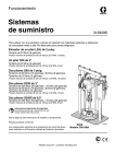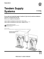
1
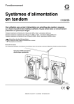
Operation
Tandem Supply
Systems
313528E
EN
For use with non-heated bulk supply of medium to high viscosity sealants and adhesive
materials. For professional use only.
Not for use in explosive atmospheres.
125 psi (0.9 MPa, 9 bar) Maximum Air Inlet Pressure - S20 3 in. rams
150 psi (1.0 MPa, 10 bar) Maximum Air Inlet Pressure - D60 and D200 3 in. rams
125 psi (0.9 MPa, 9 bar) Maximum Air Inlet Pressure - D200S 6.5 in. rams
Important Safety Instructions
Read all warnings and instructions in this manual.
Save these instructions.
US Patent Pending
The Graco Control Architecture Electric Components are Listed in Intertek’s Directory of Listed Products.
D200 Rams with Electronic
Crossover Shown
TI10865A
Contents
Related Manuals . . . . . . . . . . . . . . . . . . . . . . . . . . . 3
Translations . . . . . . . . . . . . . . . . . . . . . . . . . . . . . 3
Models . . . . . . . . . . . . . . . . . . . . . . . . . . . . . . . . . . . 4
Warnings . . . . . . . . . . . . . . . . . . . . . . . . . . . . . . . . . 8
Overview . . . . . . . . . . . . . . . . . . . . . . . . . . . . . . . . . 10
System Description . . . . . . . . . . . . . . . . . . . . . . 10
Ram Installation and Setup . . . . . . . . . . . . . . . . 10
Fluid Filter Kit Installation . . . . . . . . . . . . . . . . . 10
Grounding . . . . . . . . . . . . . . . . . . . . . . . . . . . . . 11
Integrated Air Controls . . . . . . . . . . . . . . . . . . . 11
Pneumatic Crossover System Components . . . 12
Electronic Crossover System Components . . . . 14
255468 Light Tower Accessory . . . . . . . . . . . . . 16
Communications Gateway Module . . . . . . . . . . 16
CGM Status LED Signals . . . . . . . . . . . . . . . . . 16
Display Module (Electronic Crossover Systems) 17
Fluid Control Module . . . . . . . . . . . . . . . . . . . . . 21
Electronic Crossover Operation . . . . . . . . . . . . . . 22
Pressure Relief Procedure . . . . . . . . . . . . . . . . 22
Flush Before Using Equipment . . . . . . . . . . . . . 22
Startup . . . . . . . . . . . . . . . . . . . . . . . . . . . . . . . 22
Prime . . . . . . . . . . . . . . . . . . . . . . . . . . . . . . . . . 24
Automatic Crossover . . . . . . . . . . . . . . . . . . . . . 25
Manual Crossover . . . . . . . . . . . . . . . . . . . . . . . 25
Recirculate Function . . . . . . . . . . . . . . . . . . . . . 26
Depressurize Function . . . . . . . . . . . . . . . . . . . 26
Shutdown . . . . . . . . . . . . . . . . . . . . . . . . . . . . . 27
2
Alarms . . . . . . . . . . . . . . . . . . . . . . . . . . . . . . . . . . . 28
Diagnose Alarms . . . . . . . . . . . . . . . . . . . . . . . . 28
Clear Alarms . . . . . . . . . . . . . . . . . . . . . . . . . . . 28
Alarm Codes and Troubleshooting . . . . . . . . . . 28
Appendix A - User Interface Display . . . . . . . . . . 31
Display Overview . . . . . . . . . . . . . . . . . . . . . . . . 31
Display Details . . . . . . . . . . . . . . . . . . . . . . . . . . 31
Setup Mode Screens . . . . . . . . . . . . . . . . . . . . . 33
Run Mode Screens . . . . . . . . . . . . . . . . . . . . . . 38
Fluid Filter Kit Dimensions . . . . . . . . . . . . . . . . . . 44
Technical Data . . . . . . . . . . . . . . . . . . . . . . . . . . . . 45
Graco Standard Warranty . . . . . . . . . . . . . . . . . . . 46
Graco Information . . . . . . . . . . . . . . . . . . . . . . . . . 46
313528E
Related Manuals
Related Manuals
Translations
Component Manuals in U.S. English:
This manual is available in the following languages. See
the following chart for specific languages and corresponding part numbers.
Manual
Description
313529
313526
313527
Tandem Supply Systems Repair-Parts
Supply Systems Operation
Supply Systems Repair-Parts
312375
Check-Mate® Displacement Pumps
Instructions-Parts
312376
Check-Mate® Pump Packages
Instruction-Parts
311825
311717
Chinese
313923
French
313924
German
313929
Italian
Dura-Flo Displacement Pumps (145cc,
180cc, 220cc, 290cc) Instructions-Parts
Manual
313927
Japanese
313928
Korean
Dura-Flo™ Displacement Pumps (430cc,
580cc) Instructions-Parts Manual
Carbon Steel Displacement Pump
(1000cc) Instructions-Parts Manual
313925
Spanish
311828
Dura-Flo™ Pump Packages (145cc,
180cc, 220cc, 290cc) Instructions-Parts
Manual
311826
Dura-Flo™ Pump Packages (430cc,
580cc) Instructions-Parts Manual
311833
312889
312467
312468
312469
312470
Two-Ball NXT™ Pump Packages (1000cc)
Instructions-Parts Manual
60 cc Check-Mate Displacement Pump
Repair Parts Manual
100 cc Check-Mate Displacement Pump
Repair Parts Manual
200 cc Check-Mate Displacement Pump
Repair Parts Manual
250 cc Check-Mate Displacement Pump
Repair Parts Manual
500 cc Check-Mate Displacement Pump
Repair Parts Manual
311238
NXT™ Air Motor (Nxxxxx models)
Instructions-Parts
312796
NXT™ Air Motor (Mxxxxx models)
Instructions-Parts
308213
312374
Premier® Air Motor Instructions-Parts
Air Controls Instructions-Parts
312491
Pump Fluid Purge Kit
312492
Drum Roller Kit Instruction
312493
Light Tower Kit Instruction
312864
Communications Gateway Module,
Instructions-Parts
Supply System Communications Gateway
Module Installation Kit, Instructions-Parts
313138
406681
313528E
Language
313926
™
311827
Manual
Platen Cover Kit
3
Models
Models
Check the identification plate (ID) for the 6-digit part number of your tandem system. Use the following matrix to define the construction of your system, based on
the six digits. For example, Tandem Part No. TC2414 represents a Check-Mate
tandem system (TC), pump (24), crossover option (1), and platen/ram option (4).
ID
NOTE:
Systems with the TD as the first and second digits are Dura-Flo tandem systems.
Some configurations in the following matrix cannot be built. See the Product
Selection Guide for available systems.
To order replacement parts, see Parts section in manual 313529. The digits in
the matrix do not correspond to the Ref. Nos. in the Parts drawings and lists.
TI11157A
TC
24
1
4
First and
Second Digit
Third and
Fourth Digit
Fifth Digit
Sixth Digit
Crossover Options
Platen/Ram
Options
Pump Code
TC
(Tandem
System with
Check-Mate
displacement
pump)
TD
(Tandem
System with
Dura-Flo displacement
pump)
(See Table 2
for 2-digit
Check-Mate
pump code)
(See Table 3
for 2-digit
DuraFlo pump
code)
1
2
3
4
5
6
7
8
Electronic
Crossover
(Smart
Motors
only)
✔
✔
✔
✔
✔
✔
Pneumatic
Crossover
(Standard
Motors
only)
Depressurize/
Recirculate Valve
Material
Fluid
Filter
✔
✔
✔
Carbon
Steel
✔
SST
✔
✔
✔
✔
✔
Ram Size
See Table 1
for Selections
n/a
n/a
n/a
n/a
n/a
n/a
S20, D60,
D200,
(3 in.)
D200S,
(6.5 in.)
All supply systems with DataTrak and 24 Vdc or 100-240 Vac power supplies are ETL approved.
2ECOGNIZED#OMPONENT
#-
#ERTIFIEDTO#!.#3!#3!#.O
#ONFORMSTO5,
4
313528E
Models
Table 1: Platen/Ram Options
Sixth
Digit
Platen Size
Platen Style
Platen
Material
Seal Material
Ram Size
Voltage
2
20 L (5 Gal)
Flat, Single Wiper
CS
Polyurethane
S20, 3 in.
none
3
20 L (5 Gal)
Flat, Single Wiper
SST
PTFE-Coated Nitrile
S20, 3 in
none
7
20 L (5 Gal)
Flat, Dual Wiper
CS
Polyurethane
D60, 3 in.
none
8
20 L (5 Gal)
Flat, Dual Wiper
CS
Polyurethane
D60, 3 in.
120 Vdc
9
20 L (5 Gal)
Flat, Dual Wiper
CS
Polyurethane
D60, 3 in.
24 Vdc
0
30 L (8 Gal)
Flat, Single Wiper
SST
PTFE-Coated Nitrile
D60, 3 in.
none
D
30 L (8 Gal)
Flat, Single Wiper
SST
PTFE-Coated Nitrile
D60, 3 in.
120 Vdc
E
30 L (8 Gal)
Flat, Single Wiper
SST
PTFE-Coated Nitrile
D60, 3 in.
24 Vdc
K
30 L (8 Gal)
Flat, Dual Wiper
CS
Polyurethane
D60, 3 in.
none
N
30 L (8 Gal)
Flat, Dual Wiper
CS
Polyurethane
D60, 3 in.
120 Vdc
P
30 L (8 Gal)
Flat, Dual Wiper
CS
Polyurethane
D60, 3 in.
24 Vdc
U
60 L (16 Gal)
Flat, Single Wiper
SST
PTFE-Coated Nitrile
D60, 3 in.
none
V
60 L (16 Gal)
Flat, Single Wiper
SST
PTFE-Coated Nitrile
D60, 3 in.
120 Vdc
W
60 L (16 Gal)
Flat, Single Wiper
SST
PTFE-Coated Nitrile
D60, 3 in.
24 Vdc
X
60 L (16 Gal)
Flat, Dual Wiper
CS
Polyurethane
D60, 3 in.
none
Y
60 L (16 Gal)
Flat, Dual Wiper
CS
Polyurethane
D60, 3 in.
120 Vdc
Z
60 L (16 Gal)
Flat, Dual Wiper
CS
Polyurethane
D60, 3 in.
24 Vdc
4
115L (30 Gal)
D Style
CS
EPDM
D200, 3 in.
none
1
20 L (5 Gal)
Flat, Single Wiper
SST
PTFE-Coated Nitrile
D200, 3 in.
none
6
20 L (5 Gal)
Flat, Dual Wiper
CS
Polyurethane
D200, 3 in
none
A
200 L (55 Gal)
Dual O-ring
AL
PTFE-Coated EPDM
D200, 3 in.
none
B
200 L (55 Gal)
Dual O-ring
AL
PTFE-Coated EPDM
D200, 3 in.
120 Vdc
C
200 L (55 Gal)
Dual O-ring
AL
PTFE-Coated EPDM
D200, 3 in.
24 Vdc
F
200 L (55 Gal)
Dual O-ring
AL
PTFE-Coated EPDM
D200S, 6.5 in.
none
G
200 L (55 Gal)
Dual O-ring
AL
PTFE-Coated EPDM
D200S, 6.5 in.
120 Vdc
H
200 L (55 Gal)
Dual O-ring
AL
PTFE-Coated EPDM
D200S, 6.5 in.
24 Vdc
J
200 L (55 Gal)
Dual O-ring
AL
EPDM
D200, 3 in.
none
L
200 L (55 Gal)
Dual O-ring
AL
EPDM
D200, 3 in.
120 Vdc
M
200 L (55 Gal)
Dual O-ring
AL
EPDM
D200, 3 in.
24 Vdc
R
200 L (55 Gal)
Dual O-ring
AL
EPDM
D200S, 6.5 in.
none
S
200 L (55 Gal)
Dual O-ring
AL
EPDM
D200S, 6.5 in.
120 Vdc
T
200 L (55 Gal)
Dual O-ring
AL
EPDM
D200S, 6.5 in.
24 Vdc
313528E
5
Models
Table 2: Check-Mate Pump Identification Code/Part No. Index
6
Pump Part No.
(see manual
312376)
Pump Part No.
Pump (see manual
Code
312376)
Pump
Code
NXT 200/CM 60
4A
P05LCS
4B
P05LCM
4C
P05LSS
4F
P05LSM
NXT 400/CM 60
6A
P11LCS
6B
P11LCM
6C
P11LSS
6F
P11LSM
6G
P11RCS
6H
P11RCM
6J
P11RSS
6K
P11RSM
61
P11SCS
62
P11SCM
63
P11SSS
64
P11SSM
NXT 700/CM 60
7A
P20LCS
7B
P20LCM
7C
P20LSS
7F
P20LSM
7G
P20RCS
7H
P20RCM
7J
P20RSS
7K
P20RSM
71
P20SCS
72
P20SCM
73
P20SSS
74
P20SSM
NXT 1200/CM 60
8A
P38LCS
8B
P38LCM
8C
P38LSS
8F
P38LSM
8G
P38RCS
8H
P38RCM
8J
P38RSS
8K
P38RSM
81
P38SCS
82
P38SCM
83
P38SSS
84
P38SSM
NXT 1800/CM 60
9A
P61LCS
9B
P61LCM
9C
P61LSS
9F
P61LSM
9G
P61RCS
9H
P61RCM
9J
P61RSS
9K
P61RSM
91
P61SCS
92
P61SCM
93
P61SSS
94
P61SSM
NXT 2200/CM 100
11
P40LCS
12
P40LCM
1F
P40LSS
1G
P40LSM
13
P40RCS
14
P40RCM
1H
P40RSS
1J
P40RSM
10
P40SSS
1A
P40SSM
19
P40SCS
NXT 3400/CM 100
15
P63LCS
16
P63LCM
1T
P63LSS
1U
P63LSM
17
P63RCS
18
P63RCM
1W
P63RSS
1Y
P63RSM
1B
P63SSS
1C
P63SSM
Pump
Code
Pump Part No.
(see manual
312376)
NXT 2200/CM 200
21
P23LCS
22
P23LCM
23
P23RCS
24
P23RCM
25
P23LSS
26
P23LSM
27
P23RSS
28
P23RSM
NXT 3400/CM 200
29
P36LCS
2A
P36LCM
2B
P36RCS
2C
P36RCM
2F
P36LSS
2G
P36LSM
2H
P36RSS
2J
P36RSM
NXT 6500/CM 200
2L
P68LCS
2M
P68LCM
2R
P68RCS
2S
P68RCM
2T
P68LSS
2U
P68LSM
2W
P68RSS
2Y
P68RSM
20
P68SCS
NXT 3400/CM 250
31
P29LCS
32
P29LCM
33
P29RCS
34
P29RCM
35
P29LSS
36
P29LSM
37
P29RSS
38
P29RSM
Pump
Code
Pump Part No.
(see manual
312376)
NXT 6500/CM 250
39
P55LCS
3A
P55LCM
3B
P55RCS
3C
P55RCM
3F
P55LSS
3G
P55LSM
3H
P55RSS
3J
P55RSM
Premier/CM 250
3L
P82LCS
3M
P82LCM
3R
P82LSS
3S
P82LSM
NXT 3400/CM 500
51
P14LCS
52
P14LCM
53
P14RCS
54
P14RCM
55
P14LSS
56
P14LSM
57
P14RSS
58
P14RSM
NXT 6500/CM 500
59
P26LCS
5A
P26LCM
5B
P26RCS
5C
P26RCM
5F
P26LSS
5G
P26LSM
5H
P26RSS
5J
P26RSM
Premier/CM 500
5L
P39LCS
5M
P39LCM
5R
P39LSS
5S
P39LSM
No Pump
NN
313528E
Models
Table 3: Dura-Flo Pump Identification Code/Part No. Index
Pump Part No.
Pump (see manual
Code
311828)
NXT 2200/DF 145SS
A1
P31LSS
A3
P31HSS
NXT 3400/DF 145SS
B1
P46LSS
B3
P46HSS
NXT 3400/DF 180SS
B5
P41LSS
B7
P41HSS
NXT 3400/DF 220SS
C1
P30LSS
C3
P30HSS
NXT 6500/DF 220SS
CA
P57LSS
CC
P57HSS
NXT 6500/DF 290SS
D1
P45LSS
D3
P45HSS
Premier/DF 290SS
DL
P67LSS
DR
P67HSS
313528E
Pump
Code
Pump Part No.
(see manual
311826)
NXT 3400/DF 430CS
E1
P15LCS
E2
P15LCM
E3
P15HCS
E4
P15HCM
NXT 3400/DF 430SS
E5
P15LSS
E6
P15LSM
E7
P15HSS
E8
P15HSM
NXT 6500/DF 430CS
E9
P32LCS
EA
P32LCM
EB
P32HCS
EC
P32HCM
NXT 6500/DF 430SS
EF
P32LSS
EG
P32LSM
EH
P32HSS
EJ
P32HSM
Premier/DF 430
EL
P44LSS
EM
P44LSM
ER
P44LCS
ES
P44LCM
NXT 3400/DF 580CS
F1
P12LCS
F2
P12LCM
F3
P12HCS
F4
P12HCM
NXT 3400/DF 580SS
F5
P12LSS
F6
P12LSM
F7
P12HSS
F8
P12HSM
Pump
Code
Pump Part No.
(see manual
311826)
NXT 6500/DF 580CS
F9
P22LCS
FA
P22LCM
FB
P22HCS
FC
P22HCM
NXT 6500/DF 580SS
FF
P22LSS
FG
P22LSM
FH
P22HSS
FJ
P22HSM
Premier/DF 580CS
FL
P34LSS
FM
P34LSM
FR
P34LCS
FS
P34LCM
Pump
Code
Pump Part No.
(see manual
311833)
NXT 3400/DF 1000CS
G1
P06LCS
G3
P06HCS
NXT 3400/DF 1000SS
G5
P06LSS
G7
P06HSS
NXT 6500/DF 1000CS
G9
P10LCS
GB
P10HCS
NXT 6500/DF 1000SS
GF
P10LSS
GH
P10HSS
Premier/DF 1000
GL
NR
GM
NR
GR
NR
GS
NR
NR = Not released
7
Warnings
Warnings
The following warnings are for the setup, use, grounding, maintenance, and repair of this equipment. The exclamation point symbol alerts you to a general warning and the hazard symbol refers to procedure-specific risk. Refer back
to these warnings. Additional, product-specific warnings may be found throughout the body of this manual where
applicable.
WARNING
SKIN INJECTION HAZARD
High-pressure fluid from gun, hose leaks, or ruptured components will pierce skin. This may look like just
a cut, but it is a serious injury that can result in amputation. Get immediate surgical treatment.
• Do not point gun at anyone or at any part of the body.
• Do not put your hand over the spray tip.
• Do not stop or deflect leaks with your hand, body, glove, or rag.
• Do not spray without tip guard and trigger guard installed.
• Engage trigger lock when not spraying.
• Follow Pressure Relief Procedure in this manual, when you stop spraying and before cleaning,
checking, or servicing equipment.
MOVING PARTS HAZARD
Moving parts can pinch or amputate fingers and other body parts.
• Keep clear of moving parts.
• Do not operate equipment with protective guards or covers removed.
• Pressurized equipment can start without warning. Before checking, moving, or servicing equipment,
follow the Pressure Relief Procedure in this manual. Disconnect power or air supply.
FIRE AND EXPLOSION HAZARD
Flammable fumes, such as solvent and paint fumes, in work area can ignite or explode. To help prevent
fire and explosion:
• Use equipment only in well ventilated area.
• Eliminate all ignition sources; such as pilot lights, cigarettes, portable electric lamps, and plastic drop
cloths (potential static arc).
• Keep work area free of debris, including solvent, rags and gasoline.
• Do not plug or unplug power cords, or turn power or light switches on or off when flammable fumes
are present.
• Ground all equipment in the work area. See Grounding instructions.
• Use only grounded hoses.
• Hold gun firmly to side of grounded pail when triggering into pail.
• If there is static sparking or you feel a shock, stop operation immediately. Do not use equipment
until you identify and correct the problem.
• Keep a working fire extinguisher in the work area.
8
313528E
Warnings
WARNING
WARNING
EQUIPMENT MISUSE HAZARD
Misuse can cause death or serious injury.
• Do not operate the unit when fatigued or under the influence of drugs or alcohol.
• Do not exceed the maximum working pressure or temperature rating of the lowest rated system
component. See Technical Data in all equipment manuals.
• Use fluids and solvents that are compatible with equipment wetted parts. See Technical Data in all
equipment manuals. Read fluid and solvent manufacturer’s warnings. For complete information
about your material, request MSDS forms from distributor or retailer.
• Check equipment daily. Repair or replace worn or damaged parts immediately with genuine manufacturer’s replacement parts only.
• Do not alter or modify equipment.
• Use equipment only for its intended purpose. Call your distributor for information.
• Route hoses and cables away from traffic areas, sharp edges, moving parts, and hot surfaces.
• Do not kink or over bend hoses or use hoses to pull equipment.
• Keep children and animals away from work area.
• Comply with all applicable safety regulations.
ELECTRIC SHOCK HAZARD
Improper grounding, setup, or usage of the system can cause electric shock.
• Turn off and disconnect power cord before servicing equipment.
• Use only grounded electrical outlets.
• Use only 3-wire extension cords.
• Ensure ground prongs are intact on sprayer and extension cords.
• Do not expose to rain. Store indoors.
SPLATTER HAZARD
During blowoff of platen splatter may occur.
• Use minimum drum removal air pressure.
TOXIC FLUID OR FUMES HAZARD
Toxic fluids or fumes can cause serious injury or death if splashed in the eyes or on skin, inhaled, or
swallowed.
• Read MSDS’s to know the specific hazards of the fluids you are using.
• Store hazardous fluid in approved containers, and dispose of it according to applicable guidelines.
• Always wear impervious gloves when spraying or cleaning equipment.
PERSONAL PROTECTIVE EQUIPMENT
You must wear appropriate protective equipment when operating, servicing, or when in the operating
area of the equipment to help protect you from serious injury, including eye injury, inhalation of toxic
fumes, burns, and hearing loss. This equipment includes but is not limited to:
• Protective eyewear
• Clothing and respirator as recommended by the fluid and solvent manufacturer
• Gloves
• Hearing protection
313528E
9
Overview
Overview
System Description
Fluid Filter Kit Installation
Each tandem supply system consists of two air-powered
rams; both of which are always the same size. Each ram
drives a Check-Mate pump and a platen into a drum of
material. The pump removes material from the drum
and pushes it through a supply hose to a customer-supplied header. Material flows through the header to individual dispense drops.
Some systems include a fluid filter kit. See Appendix A
- User Interface Display on page 31. Ensure that the
fluid filter stand base is level in all directions. If necessary, level the base using metal shims. Secure the base
to the floor using anchors that are long enough to prevent the filter stand from tipping.
When one drum is emptied the system performs an
automatic crossover, shutting off the air supply to the
pump on the empty ram and activating the pump on the
full ram.
1. Connect pressure sensor cable from the fluid filter
kit to port 7 of the fluid control module.
2. Connect male side of the splitter to the other end of
the pressure sensor cable.
3. Connect end of splitter cable labeled #1 to the pressure sensor on the outlet side of the filter.
Keep clear of the inactive ram, as automatic crossover
may occur unexpectedly. To repair or adjust the ram,
first follow all steps of the Pressure Relief Procedure
on page 22.
4. Connect end of splitter cable labeled #2 to the pressure sensor on the inlet side of the filter.
Ram Installation and Setup
1. Install and set up individual rams as explained in
manual 313526 (supplied).
inlet
outlet
NOTE:
See FIG. 2 on page 13 (for pneumatic crossover systems) and FIG. 3 on page 15 (for electronic crossover
systems) for examples.
2. Connect pneumatic line (AC) or CAN cable (X)
between rams.
#2
#1
#7
splitter
pressure sensor cable
10
313528E
Overview
Grounding
•
Exhaust port with muffler (BD)
•
Air motor regulator (BE): Controls air pressure to
motor.
•
Air motor slider valve (BF): turns air on and off to
the air motor. When closed, the valve relieves air
trapped between it and the air motor. Push the valve
in to shutoff. Remote DataTrak: The air solenoid
(Y, FIG. 2), the air motor slider valve (BF), and the
main air slider valve (BA) must be open for air to
flow. (See Remote DataTrak Setup section in Supply
Systems operation manual 313526.)
•
Blowoff button (BG): turns air on and off to push
the platen out of an empty drum.
The equipment must be grounded. Grounding reduces
the risk of static and electric shock by providing an
escape wire for the electrical current due to static build
up or in the event of a short circuit.
Pump: use ground wire and clamp (supplied). Loosen
grounding lug locknut and washer. Insert ground wire
end into lug slot and tighten locknut securely. Connect
ground clamp to a true earth ground.
Air and fluid hoses: use only electrically conductive
hoses with a maximum of 500 ft. (150 m) combined
hose length to ensure grounding continuity. Check electrical resistance of hoses. If total resistance to ground
exceeds 29 megohms, replace hose immediately.
BF
BE
Air compressor: follow manufacturer’s recommendations.
Dispense valve: ground through connection to a properly grounded fluid hose and pump.
BD
BG
BC
Fluid supply container: follow local code.
Solvent pails used when flushing: follow local code.
Use only conductive metal pails, placed on a grounded
surface. Do not place the pail on a nonconductive surface, such as paper or cardboard, which interrupts
grounding continuity.
To maintain grounding continuity when flushing or
relieving pressure: hold metal part of the dispense
valve firmly to the side of a grounded metal pail, then
trigger the valve.
BA
TI10438A
BB
FIG. 1. Integrated Air Controls
Air Line Accessories
See FIG. 2.
Integrated Air Controls
•
Air line drain valve (U)
The integrated air controls include:
•
Air line filter (V): removes harmful dirt and moisture from compressed air supply.
•
Second bleed-type air valve (W): isolates air line
accessories and supply system for servicing. Locate
upstream from all other air line accessories.
•
Air relief valve (attached to ram air regulator, not
visible): automatically relieves excessive pressure.
•
•
•
Main air slider valve (BA): turns air on and off to
the system. When closed, the valve relieves pressure downstream.
Ram air regulator (BB): controls ram up and down
pressure and blowoff pressure.
Ram director valve (BC): controls ram direction.
313528E
11
Overview
Pneumatic Crossover System Components
NOTE:
D200, D60, and S20 sizes are used in pneumatic
crossover systems.
FIG. 2. shows a pneumatic crossover system. Refer to
manual 313526 (supplied) for ram installation and operating instructions. The pneumatic crossover operates as
follows:
The position of the limit switch (E) on the ram determines when the air motor is turned off. Start by positioning the limit switch to trip when the ram platen (D) is 1 in.
(25 mm) from the bottom of the drum. During operation
the position may be adjusted as desired.
The bypass valve (L) allows you to prime the inactive
pump after a drum change. Open the valve to prime the
pump. Close the valve when priming is complete, and
during normal operation.
During system operation, as the ram approaches the
drum bottom, the top of the ram contacts the limit switch
(E). The limit switch shuts off air to the air motor via a
solenoid valve (Y), which stops air flow to one motor and
starts air flow to the other air motor. This allows continuous material flow and changing of material drums.
12
313528E
Overview
V
D200 Rams Shown
W
AB
V
T
AA
W
AC
U
E
E
T
U
Y
L
Y
H
A
L
H
S
C S
D
B
C
Y
S20 Ram Shown
D
TI11160A
L
H
E
FIG. 2: Component Identification, Pneumatic Crossover
Key to FIG. 2:
A
B
C
D
E
H
L
S
Ram A
Ram B
Pump (Ram A and B)
Platen (Ram A and B)
Limit Switch (Ram A and B)
Integrated Air Controls (Ram A and B); see page 11
Bypass Valve (Ram A and B)
Fluid Line (not supplied)
313528E
T
U
V
W
Y
AA
AB
AC
Main Air Line (not supplied)
Air Line Drain Valve (not supplied)
Air Filter (not supplied)
Bleed-Type Air Shutoff Valve (not supplied)
Solenoid Valve (Ram A and B)
Cable from Ram A to Limit Switch A
Cable from Ram A to Limit Switch B
Main Crossover Cable; from Ram A to Solenoid B
13
Overview
Electronic Crossover System Components
NOTE:
D200 and D60 sizes are used in electronic crossover
systems. See FIG. 3. Before you install the system,
you should be familiar with the following components.
NOTE:
Reference numbers and letters in parentheses in the
text refer to the callouts in the figures.
Both rams (A and B) include a Check-Mate Pump (C),
platen (D), integrated air controls (H), drum empty sensor (E), and fluid control module (G).
Integrated air controls (H). See page 11.
Power supply box (K).
Air motor solenoid (Y). Solenoid is on when system is on
and in Run Mode, Recirculate Mode, or Prime Mode.
Solenoid is off when system is shut off or when in
Depressurize Mode, or the ram is in an Inactive Ready
Mode. Turns on in Recirculate Mode. The solenoid LED
will illuminate when the solenoid is on.
Depressurize/recirculate fluid valve (Z). Depressurizes
system when Depressurize Mode is active. Recirculates
fluid when Recirculate Mode is active.
Only Ram A includes the display module (F) and power
supply box (K).
To depressurize the system, press the Depressurize
Drum empty sensor (E). Signals drum empty condition.
Display module (F). Mounted on Ram A only. Provides
Run Mode status screens, Setup screens, and control
keys.
Fluid control module (G). See page 21.
14
key
on the display module and select Yes when
asked if you want to depressurize the system. Follow
the Pressure Relief Procedure on page 22. Shutting
off power or removing power from the system will not
depressurize the system.
313528E
Overview
D200 Rams Shown
A
F
E
Y
B
E
X
H
Y
H
G
G
K
C
C
Z
J
D
Z
D
TI10865A
FIG. 3: Component Identification, Electronic Crossover
Key to FIG. 3:
A
B
C
D
E
F
G
H
J
K
X
Y
Z
Ram A
Ram B
Pump (Ram A and B)
Platen (Ram A and B)
Drum Empty Sensor (partially hidden; Ram A and B)
Display Module (Ram A only)
Fluid Control Module (behind rear shroud, Ram A and B)
Integrated Air Controls (Ram A and B); see page 11
Fluid Filter and Stand
Power Supply Box (behind shroud, Ram A only)
CAN Communication Cable
Air Motor Solenoid (Ram A and B)
Depressurize/Recirculate Fluid Valve (Ram A and B)
313528E
15
Overview
255468 Light Tower Accessory
Order the 255468 Light Tower Accessory as a diagnostic indicator for tandem supply systems. Refer to Light
Tower Kit manual for installation instructions. See Table
4 for a description of light tower signals.
Table 4: Light Tower Signals
Signal
Description
Green on only
System is powered up and there
are no error conditions present.
Yellow flashing
A low priority error exists.
Yellow on
A medium priority error exists.
Red flashing
A high priority error exists.
Red on
The system is shut down due to
error conditions.
Communications Gateway
Module
CGM Status LED Signals
Signal
Description
Green on
System is powered up
Yellow
Internal communication in progress
Red
Solid
CGM hardware failure
*Red
(7 flashes)
Data map load failure
Incorrect data map for fieldbus type
No data map loaded
*The red LED (F) will flash a code, pause, then repeat.
See for diagnostic information in CGM manual 312864.
NOTE: Verify that you are using the correct token for
your system and reinstall token. If fails, order new
token.
The Communications Gateway Module (CGM) provides
a control link between Graco Control Architecture based
systems and a selected fieldbus. This provides the
means for remote monitoring and control by external
automation systems.
Data provided by the CGM to the fieldbus depends on
which Graco Control Architecture based system and
fieldbus are connected. A data map supplied on a map
token is defined for this pairing. Once the data map has
been loaded into the CGM, it is stored internally, and the
map token is no longer required for operation.
16
313528E
Overview
Display Module (Electronic Crossover Systems)
FIG. 4: Display Module
Table 5: Display Module Button Functions
Key
System On/Off
Cancel
Setup
Function
Powers air motor solenoid ON and OFF from Ram Operation screen (FIG. 29, page 38).
• When ON, the air motor solenoid is ON and the pump of the active ram is pressurized.
• When OFF, the air motor solenoids are OFF.
CAUTION: Turning the air motor solenoid OFF relieves pressure from the pump motor. It does
not depressurize the fluid pressure. Follow the Pressure Relief Procedure, page 22.
NOTE: The ram up/down and blowoff air is independent of the electronic controls and can be
operated anytime the main air slider valve is open and air pressure is available.
Cancel a selection or number entry while in the process of entering a number or making a
selection.
Toggle between run and setup screens.
• Setup changes can be made while system is operating.
•
Enter
If setup screens are password protected, button toggles between run and password entry
screen.
Opens drop down menus on Setup fields.
Press to enter changes and make a selection.
Arrows Left/Right Navigate left or right to a new screen.
Navigate left or right within a screen while in Jump In mode. See Appendix A - User Interface
Display, page 31, for more information.
Arrows Up/Down Navigate up or down within a screen or to a new screen.
• Move between selections within a drop-down menu.
•
313528E
Increment or decrement the selected numerical field within a selection menu.
17
Overview
Table 5: Display Module Button Functions
Key
Soft Key
Function
Soft keys activate the mode or action represented by the icon above each button in the LCD.
See Table 6 for soft key modes and actions.
Table 6: Display Soft Key Icons
Icon
Function
Depressurize
Depressurize relieves fluid pressure from the pump outlet to below the platen on the currently
active ram.
If system is pressurized, press button.
•
When prompted to depressurize the system, select
or
. Depressurizing the
active ram will depressurize both rams.
NOTE: If additional user-supplied check valves have been added to the system, only the active
ram will be depressurized. You must perform manual crossover and select depressurize again
to depressurize both rams. See Crossover section of this table on page 19.
If system is depressurized, press button.
•
Pump Prime
When prompted to pressurize the system, select
or
.
Pump Prime
• Tandem ram: if pump is off, activates the air solenoid on the active ram;
• Tandem ram: if pump is on, activates the air solenoid on the inactive ram which enables you
to purge air and prime the pump;
• Single ram: activates air solenoid whether or not pump is on;
• clears the Pump Not Primed deviation or alarm (depending on setup selection); and
• resets the drum volume remaining to the drum fill volume setpoint for pump being primed.
Press button.
•
When prompted to prime the ram, select
to prime.
Press button to exit Prime Mode or to reset counter to the prime time.
•
Recirculate
When prompted to exit Prime Mode, select
to exit or
to reset prime counter.
Recirculate Mode pumps fluid from the drum, through the pump, and back into the drum on the
currently active ram.
Set motor air regulator to 30 psi (0.2 MPa, 2.1 bar) before pressing Recirculate key.
If system is not in Recirculate Mode, press button.
•
When prompted to turn recirculation on, select
or
. Adjust motor air regulator to
or
.
obtain desired flow rate.
If system is in Recirculate Mode, press button.
•
18
When prompted to turn recirculation off, select
313528E
Overview
Table 6: Display Soft Key Icons
Icon
Function
Crossover
Crossover key transitions the active ram to inactive, and inactive ram to active. Available on
Warm Melt Tandem Supply Systems only.
NOTE: If an alarm is present on the inactive ram, crossover will not be successful. Manual
crossover is disabled in single ram operation.
Press button.
•
Jump In
When prompted to initiate a crossover, select
In screens that have editable fields, press
or
.
to access the fields and make changes. See
Appendix A - User Interface Display, page 31, for more information.
313528E
19
Overview
User Interface Display
NOTE: For details regarding the user interface display see Appendix A - User Interface Display, page
31.
Display Screen Components
The following figure calls out the navigational, status, and general informational components of each display screen.
Current Date and Time
Navigation
Status
Mode
Function Display
Displays soft keys
that are active for
particular screen
Soft Keys
FIG. 5: Display Screen Components (example of tandem system)
20
313528E
Overview
Fluid Control Module
Table 7: Fluid Control Module Sensor Connections
Connection
Ram
Sensor Description
1
Ram A and Ram B
Air motor solenoid (white), light tower (green), drum low (yellow), drum empty (black)
2
Ram A
Light tower
3
Ram A + B
Fluid depressurize/recirculate solenoid
4
not used
not used
5
Ram A and Ram B
Air motor reed switch, sensors
6
not used
not used
7
Ram A
Filter pressure at inlet and outlet
CAN communication
cable 1
Ram A
From Ram A Fluid Control Module to Display Module.
CAN communication
cable 2
Ram A and Ram B
49 ft (15 m) from Ram A Fluid Control Module to Ram B Fluid
Control Module.
3
7
4
CAN Cable 2
6
TI12337A
5
TI12336A
CAN Cable 1
FIG. 6: Fluid Control Module Sensor Connections
313528E
21
Electronic Crossover Operation
Electronic Crossover Operation
NOTE:
These instructions are for the display module functions used on tandem systems. For basic ram and
pump operation, refer to the component manuals
supplied.
Pressure Relief Procedure
highlight
. If system is On, display will
. Select
Flush Before Using Equipment
The pump was tested with lightweight oil, which is left in
the fluid passages to protect parts. To avoid contaminating your fluid with oil, flush the pump with a compatible
solvent before use. See your pump manual for flushing
directions.
1. Lock the gun/valve trigger.
2. Press On/Off key
If you suspect that the spray tip/nozzle or hose is completely clogged, or that pressure has not been fully
relieved after following the steps above, very slowly
loosen the tip guard retaining nut or hose end coupling
and relieve pressure gradually, then loosen completely.
Now clear the tip/nozzle or hose.
to turn off.
Startup
1. On both ram A and B, turn on the main air slider
valve (BA). Set the ram director valve (BC) to the
down position. The ram will slowly drop.
2. Turn on the air motor slider valve (BF) on both ram A
and B.
BF
BE
FIG. 7: System Function Screen
3. Turn off the air motor slider valve (BF) on both ram A
and B.
BC
4. On both ram A and B, turn off the main air slider
valve (BA). Set the ram director valve (BC) to the
down position. The ram will slowly drop.
BA
5. Unlock the gun/valve trigger.
6. Hold a metal part of the gun/valve firmly to the side
of a grounded metal pail, and trigger the gun/valve
to relieve pressure.
7. Lock the gun/valve trigger.
BB
TI10438A
FIG. 8. Integrated Air Controls
8. On both ram A and B, open the fluid line drain valve
and/or the pump bleed port. Have a container ready
to catch the drainage.
22
313528E
Electronic Crossover Operation
3. Turn on the power on/off switch at the back of the
power supply box on ram A. The Power Up screen
will appear. See FIG. 9.
FIG. 9: Power Up Screen
4. Press On/Off key
. If system is Off, press
to turn the system on.
5. See FIG. 10. The Ram Operation screen displays
which ram (A or B) is active and how much volume
is remaining in each drum. The fluid line is shown
filled indicating the system is on.
6. The air motor solenoid LED will illuminate.
Active ram is
highlighted
Fluid line shown filled
when system is ON
Volume
Remaining
FIG. 10: Ram Operation Screen
313528E
23
Electronic Crossover Operation
Prime
NOTE: To exit Prime Mode before the timer expires,
press the Pump Prime key
. The display
prompts the operator to confirm. See FIG. 13. Select
to exit prime.
1. Make sure the system is at required temperature.
2. To prime the active ram, ensure that the system is
on and not in Run Mode. To prime the inactive ram,
ensure that the system is on and in Run Mode.
FIG. 13: Exit Prime Mode Confirmation
NOTE: To extend the prime time counter, select
FIG. 11: Ram Operation Screen - Tandem System
in FIG. 13. Display prompts operator to confirm. See
FIG. 14. Select
to reset.
3. If using a manual dispense valve, unlock the dispense valve trigger and place dispense valve over a
waste container.
4. Press the Pump Prime key
. The display
prompts the operator to confirm. See FIG. 12. Select
to begin prime.
FIG. 14: Reset Prime Time Counter Confirmation
FIG. 12: Prime Confirmation
5. When the timer expires the air motor solenoid LED
will turn off.
6. Prime the system until a smooth flow of material dispenses from the dispense valve.
7. Lock the dispense valve trigger lock.
24
313528E
Electronic Crossover Operation
Automatic Crossover
Manual Crossover
Manual crossover can only be initiated if the following
conditions are met:
Keep clear of the inactive ram, as automatic crossover may occur unexpectedly. To repair or adjust the
ram, first follow all steps of the Pressure Relief Procedure on page 22.
The automatic crossover feature allows continuous flow
and prevents system shutdown. If the active ram
encounters a pump runaway, drum empty, or air solenoid disconnected alarm it will attempt an automatic
crossover to the inactive ram.
The system will generate a crossover error if the active
ram attempts an automatic crossover while the inactive
ram has a pump runaway, drum empty, air solenoid disconnected, or not primed alarm.
•
inactive ram is not in the drum empty error condition.
•
pump runaway and not primed alarms do not exist.
To initiate a manual crossover to the inactive ram:
1. From the Ram Operation screen, press the Crossover key
. The display prompts the operator to
confirm.
2. Select
or select
to confirm manual crossover operation
to cancel.
FIG. 15: Crossover Function Screen
NOTE: If the active ram has a pump runaway error or
drum empty error, the system will attempt an automatic crossover.
313528E
25
Electronic Crossover Operation
Recirculate Function
Depressurize Function
Recirculate mode pumps fluid from the drum, through
the pump, and back into the drum on the currently active
ram.
Follow the Pressure Relief Procedure on page 22.
Shutting off power or removing power from the system will not depressurize the system.
To enter Recirculate mode:
1. Set the motor air regulator to 30 psi (0.2 MPa, 2.1
bar).
2. From the Ram Operation screen, press the Recirculate key
. The display prompts the operator to
When the system is pressurized the depressurize function relieves fluid pressure from the pump outlet to below
the platen on the currently active ram. However, when
the system is depressurized pressing the depressurize
key will restore fluid pressure.
confirm.
Depressurize System
3. Select
to confirm recirculation or select
to
cancel.
From the Ram Operation screen, press the Depressurize key
firm. Select
. The display prompts the operator to conto confirm depressurize or select
to cancel.
FIG. 16: Enter Recirculate Mode
4. Adjust motor air regulator to obtain desired flow
rate.
NOTE:
While in Recirculate Mode, the manual crossover
function cannot be used and the inactive ram cannot be primed.
FIG. 17: Depressurize Function Screen
To exit Recirculate Mode, press the Recirculate key
. The display prompts the operator to confirm.
Select
to confirm or select
to cancel. See FIG.
16.
NOTE:
You must exit Recirculate Mode before depressurizing or initiating a crossover.
26
313528E
Electronic Crossover Operation
Shutdown
Turning the system OFF relieves pressure from the
pump motor. It does not depressurize the fluid pressure. Follow the Pressure Relief Procedure, page
22.
Follow the procedure below for normal system shut
down, such as at the end of the work day.
NOTE:
The ram up/down and blowoff air is independent of
the electronic controls and can be operated anytime
the main air slider valve is open and air pressure is
available.
1. Press
while in the Ram Operation screen to
turn off the air motor. Select
2. Press
to confirm.
while in the Heater Run screen to turn
off the heaters. Select
to confirm.
3. Follow the Pressure Relief Procedure, page 22.
313528E
27
Alarms
Alarms
Supply system alarms alert you to a problem and help
prevent system shutdown or application errors. If an
alarm occurs, operation may stop and the following
occurs.
•
Light tower indication changes (if equipped)
•
Status bar on the display shows the alarm description
Diagnose Alarms
See Alarm Codes and Troubleshooting, page 28, for
causes and solutions to each alarm code.
Clear Alarms
Alarms are cleared by the solution(s) listed in the following table or from the screen in which they appear. Refer
to Alarm Codes and Troubleshooting, page 28, for
details.
Alarm Codes and Troubleshooting
Alarm
Code
Alarm Problem
Cause
Solution
Clear Alarm
Fluid Control Module
CB1X
A - Communication Error Ram A Not Found
Ram cannot communicate with Verify that power is supFCM A.
plied.
Alarm automatically
cleared by solution.
Check that CAN cables are
connected.
Verify that selector switch is
set correctly.
Replace FCM A.
CB2X
B - Communication Error Ram B Not Found
Ram cannot communicate with Verify that power is supFCM B.
plied.
Alarm automatically
cleared by solution.
Check that CAN cables are
connected.
Verify that selector switch is
set correctly.
Replace FCM B
B61X
Crossover Error (Ram A)
B62X
Crossover Error (Ram B)
Inactive ram has a Not Primed Set inactive ram to Prime
Cleared from Ram Alarm
alarm.
mode to automatically clear screen. See Appendix A alarm.
User Interface Display,
There is a Runaway alarm
Correct runaway condition page 31.
and clear alarm on Status
screen 1.
There is a Drum Empty alarm. Replace empty drum with
full drum to clear.
28
313528E
Alarms
Alarm
Code
Alarm Problem
Cause
Solution
Clear Alarm
Fluid Control Module (continued)
DA1X
Pump Runaway A
DA2X
Pump Runaway B
Pump is running faster than
set runaway limit due to:
Correct runaway condition
and clear alarm.
Cleared from Ram Alarm
screen. See Appendix A User Interface Display,
page 31.
Drum empty sensor has been
activated.
Replace empty drum with
full drum to clear.
Alarm automatically
cleared by solution.
The pump is not primed.
Set ram to Prime mode to
automatically clear alarm,
or manually clear alarm
from Ram Alarm screen.
Cleared from Ram Alarm
screen or Ram Operation
screen. See Appendix A User Interface Display,
page 31.
Solenoid unplugged.
Check that solenoid cable
is connected.
Alarm automatically
cleared by solution.
Damaged solenoid / wires.
Inspect solenoid wires for
damage.
Alarm automatically
cleared by solution.
•
•
•
•
L11X
A - Drum Empty
L12X
B - Drum Empty
DB1X
A - Not Primed
DB2X
B - Not Primed
WJ1X
A - Air Solenoid Disconnected
WJ2X
B - Air Solenoid Disconnected
DK1X
A - Air Motor Sensor Error
DK2X
B - Air Motor Sensor Error
Increased air pressure.
Increased fluid output.
Exhausted fluid supply.
Open fitting, hose, drain,
or bleed valve.
System has seen multiple up See air motor manual.
strokes without a down stroke,
or multiple down strokes without an up stroke.
Damaged or disconnected air
motor sensors.
Cleared from Ram Alarm
screen. See Appendix A User Interface Display,
page 31.
Check that air motor sensors are connected.
Inspect air motor sensor
harness for damage.
L21X
A - Drum Low Deviation
L22X
B - Drum Low Deviation
WK1X
A - Fluid Solenoid Disconnected Deviation
WK2X
B - Fluid Solenoid Disconnected Deviation
ML1X
A - Rebuild Platen Seals
ML2X
B - Rebuild Platen Seals
MA1X
A - Rebuild Pump
MA2X
B - Rebuild Pump
313528E
Drum low sensor has been
activated.
Replace empty drum with
full drum to clear.
Deviation automatically
cleared by solution.
Solenoid unplugged.
Check that solenoid cable
is connected.
Deviation automatically
cleared by solution.
Damaged solenoid wires.
Inspect solenoid cable for
damage.
Counter has reached programmed platen maintenance
interval.
Perform platen mainteCleared from Maintenance
nance; see Supply Sysscreen. See Appendix A tems Repair-Parts manual. User Interface Display,
page 31.
Counter has reached programmed pump maintenance
interval.
Perform pump maintenance. See Check-Mate
Displacement Pump manual.
Cleared from Maintenance
screen. See Appendix A User Interface Display,
page 31.
29
Alarms
Alarm
Code
Alarm Problem
Cause
Solution
Clear Alarm
Fluid Control Module (continued)
DD1X
A - Pump Diving
DD2X
B - Pump Diving
Pump leak.
Ram air pressure set too low.
Worn valve or packings.
Cleared from Ram Alarm
See Check-Mate Displace- screen. See Appendix A ment Pump manual.
User Interface Display,
page 31.
Increase air pressure to
ram until diving stops.
Material flow rate exceeds
ability of ram to feed pump.
Decrease pump air pressure to slow cycle rate.
Decrease pressure until
diving stops.
Reminder when maintenance
counter was last reset.
Reset on Maintenance
Screen 2.
Cleared when reset from
Maintenance Screen 2.
001X
A - Platen Seals Maintenance Reset
or
A- Pump Maintenance
Reset
002X
B - Platen Seals Maintenance Reset
or
B- Pump Maintenance
Reset
MGDX
Filter Pressure Drop Low
Pressure drop from filter inlet
to outlet is below minimum
drop setpoint for 10 consecutive cycles. Filter element has
collapsed or is not present.
Replace filter element.
Cleared when reset from
Status Screen 2.
Filter Pressure Drop High
Pressure drop from filter inlet
to outlet is above maximum
drop setpoint for 10 consecutive cycles. Filter is clogged.
Remove and clean filter.
Cleared when reset from
Status Screen 2.
30
313528E
Appendix A - User Interface Display
Appendix A - User Interface Display
Display Overview
Display Details
The user interface display is divided into two main functions: Setup mode and Run mode.
Power Up Screen
Setup Mode Functions
The setup mode functions enable users to:
•
•
•
•
•
•
•
•
The following screen appears when the display module
is powered up. It remains on while the display module
runs through initialization and establishes communication with other components in the system.
set and change the password;
configure system parameters;
set heat zone parameters;
schedule maintenance parameters;
configure system hardware settings;
set and change display units and format for all
other screens;
set pump size and drum fill volume;
and view software information for each system
component.
Run Mode Functions
The run mode functions enable users to:
•
•
•
•
•
•
•
view current flow rate and drum volume;
view temperature for heat zones;
view system job totals and grand totals, and
reset totals;
view current pressures;
view and reset maintenance counters;
view and clear individual alarms;
and view the alarm log.
FIG. 18: Power Up Screen
Menu Bar
The menu bar appears at the top of the screen, and
consists of the following components.
FIG. 19: Menu Bar
Date and Time
The date and time are always displayed in one of the following formats. The time is always displayed as a
24-hour clock.
•
DD/MM/YY HH:MM
•
MM/DD/YY HH:MM
Navigation
The navigation section, which is to the right of the date
and time, indicates the active screen with the center,
highlighted icon. The left and right arrows indicate there
are more screens that can be accessed within a mode.
313528E
31
Appendix A - User Interface Display
Navigation within Screens
Status
The current system status is displayed on the right of the
menu bar. If there is an error, an event icon and either a
text description of the event or the standard error code
for the event is displayed. If there are no errors or deviations, nothing is displayed.
Press
to open drop-down menus on Setup
screens. Also, press
to enter changes or make a
selection.
Mode
The mode section displays the current system mode.
The current mode is highlighted.
Press
Error
to navigate to new screens and to
navigate left and right within a screen. Also press
The current system error is displayed in the menu bar.
There are four possibilities:
Icon
Function
No Icon
No information or no error has occurred
Advisory
select digits within a field to change.
Press
to navigate to new screens and to
navigate up and down within a screen. Also press
to move between fields within a drop-down
Deviation
menu, and to increment or decrement numbers within a
field.
Alarm
Soft Keys
Icons above the soft keys indicate which mode or action
is associated with each soft key. Soft keys that do not
have an icon above them are not active in the current
screen.
Jump In/Jump Out
In screens that have editable fields, press
to
access the fields and make changes. When changes
are complete press
32
to exit edit mode.
313528E
Appendix A - User Interface Display
Setup Mode Screens
Setup mode screens are divided into six sections: password, system setup, heat zone setup, maintenance
setup, hardware setup, and advanced setup.
System Setup
The System Setup screen enables users to configure
system settings for the ram(s). Press
to access the
Password Screen
fields and make changes. Press
While in Run mode, press the Setup
button. If the
password is not set to 0000, the Password screen will
appear. Enter the password to continue to Setup mode.
NOTE: Upon the first system startup, the System
Setup screen will display. Otherwise, the last setup
screen viewed will display.
Icon
Function
Select tandem operation, ram A only operation, or ram B only operation.
Select if a Not Primed event will issue an
alarm or deviation.
Set number of minutes (1-9) for priming.
Set Password
To set the password, press
Press
to exit edit mode.
to enter the screen.
to select digit to change. Press
Set pump cycles per minute that will issue
a pump runaway alarm. Set between 0 and
99; default setting is 60 cycles; 00 setting
disables this function.
to set value for each digit. Press
again to enter the password.
FIG. 21: System Setup
FIG. 20: Password Screen
313528E
33
Appendix A - User Interface Display
Maintenance Setup Screen
The Maintenance Setup screen enables users to set
maintenance intervals for rebuilding platen seals and
rebuilding the pump.
Icon
Function
Set the number of drums (0-9999) between
platen seal maintenance. Setting the number of pump cycles to 0 disables this function. If using a tandem system, set for each
ram. A rebuild platen seals error is issued
when maintenance is required. See Alarm
Codes and Troubleshooting on page 28.
Set the number of pump cycles (0-9999)
between pump maintenance. Setting the
number of pump cycles to 0 disables this
function. If using a tandem system, set for
each pump. A rebuild pump error is issued
when maintenance is required. See Alarm
Codes and Troubleshooting on page 28.
FIG. 22: Maintenance Setup
34
313528E
Appendix A - User Interface Display
Hardware Setup Screens
The Hardware Setup screens enable users to specify if
specific hardware is installed on the system and to
adjust hardware settings. Press
Monitor the filter pressure readings through the normal
range of flow with a clean filter to establish the initial limit
settings.
to scroll
through the Hardware Setup screens. Once in the
desired Hardware Setup screen, press
the fields to make changes. Press
to access
to exit edit
mode.
NOTE: Must exit edit mode to scroll through the
Hardware Setup screens.
FIG. 23: Hardware Setup Screen 1 (Filter)
Hardware Setup Screen 1
This screen enables users to specify if a fluid filter monitor is installed, and set the high and low limits for the
pressure drop across the filter.
Icon
Function
Select what type of error will be issued if filter pressure drops below the low limit or
raises above the high limit. Select
to
disable filter monitoring or if there is no filter installed on the system.
Set low limit (0-1000 psi) for pressure drop
that will issue an error. Set the low limit to
detect a filter element collapse or a missing
element.
Set high limit (0-5000 psi) for pressure drop
that will issue an error. Set the high limit to
detect a clogged filter.
Hardware Setup Screen 2
This screen enables users to specify if a fluid solenoid is
installed, and if a drum low sensor is installed. The fluid
solenoid controls the depressurize/recirculate valve.
Icon
Function
Select if fluid solenoid is installed on system. Set for A and B rams.
Select if drum low sensor is installed on
system. Set for A and B rams.
FIG. 24: Hardware Setup Screen 2
313528E
35
Appendix A - User Interface Display
Advanced Setup Screens
Advanced Setup Screen 2
The Advanced Setup screens enable users to set units,
adjust values, set formats, and view software informa-
This screen enables users to set the pump size (in
cc/cycle) and the drum fill volume (in volume units). The
drum fill volume is the amount of material in a new drum,
which is used to calculate the volume of material
remaining during operation.
tion for each component. Press
to scroll
through the Advanced Setup screens. Once in the
desired Advanced Setup screen, press
the fields to make changes. Press
to access
to exit edit
mode.
Icon
NOTE: Must exit edit mode to scroll through the
Advanced Setup screens.
Advanced Setup Screen 1
This screen enables users to set units that display on
other screens.
NOTE: On two-zone and four-zone enclosure accessory kit, only
Icon
NOTE: These values must be entered accurately for
the volume remaining estimates on the Ram Operation screen to be accurate.
and
settings are available.
Function
Set pump size (cc/cycle) for each ram.
Check-Mate: Select between 60, 100,
200, 250, and 500.
Dura-Flo: Select between 145, 180,
220, 290, 430, 580, and 1000.
Set fill volume for each drum. Use digits 1-9999.
Change between a Check-Mate or
Dura-Flo pump.
Function
Select units of measurement for volume.
Select between cycles/gal. gal., oz., and
liters/cc.
Set units of measurement for maintenance
intervals. Select between 1000 cycles,
drums, gal., and liters.
Set units of measurement for pressure.
Select between psi and bar.
Set the password. Use digits 0-9999;
0000 = no password.
FIG. 26: Advanced Setup Screen 2
FIG. 25: Advanced Setup Screen 1
36
313528E
Appendix A - User Interface Display
Advanced Setup Screen 3
Advanced Setup Screens 4 and 5
This screen enables users to set the date, time, and
date format.
These screens display the software part number and
version information for the system components. Only
system components that are detected via the system
data bus will be displayed on these screens.
Icon
Function
Set date format. Select between
MM-DD-YYYY and DD-MM-YYYY.
Set current date.
Set current time.
Icon
Function
Controller software part number and version.
Display software part number and version.
Fieldbus gateway software part number
and version.
Temperature controller software part number and version.
FIG. 27: Advanced Setup Screen 3
FIG. 28: Advanced Setup Screens 4 and 5
313528E
37
Appendix A - User Interface Display
Run Mode Screens
Run mode screens are divided into six sections: ram
operation, heat zone operation, current system status,
preventative maintenance schedule, current alarms, and
error reports. The system starts in Run mode. If the system is in Setup mode, press
See Electronic Crossover Operation, page 22, for
instructions on all of these procedures.
Active ram is
highlighted
to enter Run mode.
Flow
rate
Fluid line shown filled
when system is ON
Ram Operation Screen
The Ram Operation screen displays which ram (A or B)
is active, and how much volume remains in each drum.
This screen also displays the flow rate of the active ram.
When the fluid line is shown filled the system is on.
Volume
Remain
-ing
Depending on the current system status, users can perform the following procedures from the Ram Operation
screen:
Current
mode
•
•
•
•
•
38
turn the air motor on and off;
depressurize and pressurize the system;
recirculate fluid within the active ram;
prime the pump(s);
and perform a manual crossover on tandem systems.
FIG. 29: Ram Operation Screen - Tandem System
The Ram Operation screen will display the appropriate
icon and highlight the corresponding soft key if the system is:
•
depressurized
,
•
in Recirculate mode
•
or if a ram is in Prime mode
,
.
313528E
Appendix A - User Interface Display
Status Screen
Alarm Screen
This screen displays the job totals and grand totals. If
there is a filter or an error issued, there will be additional
The alarm screens display the type of alarm currently
occurring on each ram. Once an alarm is resolved, use
this screen to clear the alarm.
screens. Press
to scroll to through the
NOTE: For more information regarding alarms. See
Alarms on page 28.
Status screens.
NOTE: If an alarm is issued, the Alarm screen will be
the first status screen shown.
Icon
Icon
Alarm
Code
B61X
B62X
Function
Job total column; indicates pump cycle
count total for a single job.
DA1X
DA2X
Grand total column; indicates pump cycle
count total for all jobs.
DB1X
DB2X
Displays pump cycle count for Ram A for
a single job and all jobs.
Displays pump cycle count for Ram B for
a single job and all jobs.
DK1X
KD2X
Displays pump cycle count for entire system for a single job and all jobs.
DD1X
DD2X
L11X
L12X
Function
Crossover Error
A crossover to a pump with an
error was attempted.
Pump Runaway
Pump is running faster than the
runaway limit.
Pump Not Primed
A new drum has not been
primed.
Air Motor Sensor Error
Air motor sensor detects a fault
in the pump motion.
Pump Diving
Pump leak or ram air pressure is
too low.
Drum Empty
Drum for ram A or ram B is
empty.
FIG. 30: Status Screen 1
To reset a job total for a single ram (A or B), press
to access the fields, navigate to the value, and press
. When prompted, press
FIG. 31: Ram Alarm Screen
to confirm. If the job
total is reset, A and B totals will also be reset. Press
To clear an alarm, press
to access the fields, navi-
to exit edit mode.
gate to the alarm icon, and press
. When
NOTE: Grand totals cannot be reset.
prompted, press
to confirm. Press
to exit edit
mode.
313528E
39
Appendix A - User Interface Display
Maintenance Screen
The maintenance screen enables operators to establish
a preventive maintenance schedule based on the system application and repair history. This screen displays
the number of maintenance units remaining before preventive maintenance is due for the platen seals and
pump.
NOTE: If a maintenance interval is set to 0, the display will be a dash.
Icon
Function
Current count remaining until platen
requires maintenance. Platen mainte-
FIG. 32: Maintenance Screen
nance is reported in drums
To reset a counter, press
.
Current count remaining until pump
requires maintenance. Pump maintenance is reported in units set by the maintenance unit control
in the Advanced
gate to the value, and press
press
to confirm. Press
to access the fields, navi. When prompted,
to exit edit mode.
Setup screen 1. The example shown in
FIG. 32 is set to units of 1000 pump cycles
.
40
313528E
Appendix A - User Interface Display
Filter Screen
Over or Under Pressure Alarm
NOTE: The filter screen is only available if the fluid
filter option is enabled. See Hardware Setup Screen
2, page 35.
If the differential pressure measured across the fluid filter for at least five strokes is greater than the high limit or
less than the low limit value set in the Hardware Setup
Screen 1, and alarm or deviation is indicated; see FIG.
34. Whether an alarm or deviation is issued depends on
the error type set in the Hardware Setup Screen 1.
This screen displays the fluid filter inlet pressure, outlet
pressure, and the differential pressure across the filter.
Icon
Function
Fluid filter inlet pressure.
Fluid filter outlet pressure.
Differential pressure across the fluid filter.
FIG. 34: Fluid Filter Screen with Alarm
To clear a filter alarm or deviation, press
fluid filter screen. Then press
from the
on the confirmation
screen.
FIG. 33: Fluid Filter Screen
FIG. 35: Fluid Filter Screen with Alarm
313528E
41
Appendix A - User Interface Display
Report Screens
The five report screens display a chronological list of the
most recent 20 errors. See Alarm Codes and Troubleshooting, page 28, for details regarding each alarm
code.
Icon
Function
Chronological order of errors as they
occur.
Date when error occurred.
Time when error occurred.
Error code.
Press
to scroll to through the five report
screens.
FIG. 36: Report Screen
42
313528E
Appendix A - User Interface Display
313528E
43
Fluid Filter Kit Dimensions
Fluid Filter Kit Dimensions
NOTE:
Refer to the Related Manuals list on page 3 to find
the correct manuals that list the dimensions of the
rams, pumps, and other components.
F
G
Key
A
52.25 in. (1327 mm)
B
11 in. (279 mm)
C
14 in. (356 mm)
D
17 in. (432 mm)
E
14. in. (356 mm)
F (fluid inlets)
1 in. npt(f)
G (fluid outlet)
1 in. npt(f)
Filter Element Mesh Sizes
Part No.
Mesh
515219
60
515220
50
515221
40
515222
30 (standard)
A
B
C
E
D
TI11158A
44
313528E
Technical Data
Technical Data
Max air input pressure (supply system)
psi (MPa, bar) / Air inlet size
S20 - 3 in. single post, 5 gal. (20 L) . . . . . . . . . . . . . .
125 psi (0.9 MPa, 9 bar) / 1/2 npt(f)
D60 - 3 in. dual post, 16 gal. (60 L), 5 gal. (20 L), 30 gal.
(115 L) . . . . . . . . . . . . . . . . . . . . . . . . . . . . . . . . . . . .
150 psi (1.0 MPa, 10 bar) / 3/4 npt(f)
D200 - 3 in. dual post, 55 gal. (200 L), 30 gal. (115 L),
16 gal. (60 L), 8 gal. (30 L), 5 gal. (20 L) . . . . . . . . . .
150 psi (1.0 MPa, 10 bar) / 3/4 npt(f)
D200s - 6.5 in. dual post, 55 gal. (200 L), 30 gal. (115 L) 125 psi (0.9 MPa, 9 bar) / 3/4 npt(f)
Max fluid, air working pressure, and weight
(displacement pump) . . . . . . . . . . . . . . . . . . . . . . . . . . . .
Pump Wetted parts . . . . . . . . . . . . . . . . . . . . . . . . . . . . .
For Check-Mate pump packages, see manual 312376.
For Dura-Flo pump packages, see manuals 311826,
311828, 311833.
For Check-Mate displacement pumps, see manual
312375.
For Dura-Flo displacement pumps, see manuals
311717, 311825, 311827.
Platen/Ram Codes (page 5): Part number, size, platen;
Wetted parts
A, B, C, F, G, H: 255662, 55 gal. (200 L) . . . . . . . . .
PTFE, EPDM, PTFE coated aluminum, zinc plated
carbon steel, 316 sst
J, L, M, R, S, T: 255663, 55 gal. (200 L) . . . . . . . . . .
EPDM, aluminum, zinc plated carbon steel, 316 sst
4: 255661, 30 gal. (115 L) . . . . . . . . . . . . . . . . . . . . .
zinc plated carbon steel, EPDM, sst, fluoroelastomer
2: 257728, 5 gal. (20 L) . . . . . . . . . . . . . . . . . . . . . . .
Electroless nickel, polyurethane, carbon steel, polyethylene, nitrile, zinc plated carbon steel, buna, 316 sst
17-4PH sst
1, 3: 257729, 5 gal. (20 L)
D, E: 257734, 8 gal. (30 L)
U, V, W: 257738, 16 gal. (60 L) . . . . . . . . . . . . . . . . .
Stainless steel, polyurethane, PTFE coated nitrile, polyethylene, nitrile, PTFE, 303 sst, 304 sst, 316 sst,
17-4PH sst
6, 7, 8, 9: 257731, 5 gal. (20 L)
K, N, P: 257736, 8 gal. (30 L)
X, Y, Z: 257741, 16 gal. (60 L) . . . . . . . . . . . . . . . . . .
Electroless nickel, aramind reinforced elastomer, rubber-based PSA, polyurethane, polyethylene, nitrile, zinc
plated carbon steel, buna, 1018 carbon steel, 304 sst,
316 sst, 17-4PH sst
Ambient operating temperature range (supply system)
Sound data . . . . . . . . . . . . . . . . . . . . . . . . . . . . . . . . . . . .
External power supply requirements (DatraTrak)
AC power units. . . . . . . . . . . . . . . . . . . . . . . . . . . . . .
DC power units . . . . . . . . . . . . . . . . . . . . . . . . . . . . .
313528E
32-120 °F (0- 49°C)
See separate air motor manual.
100-240 Vac, 50/60 Hz, single phase, 1.2 amps max
draw
24 Vdc, 1.2 amps max draw
45
Graco Standard Warranty
Graco warrants all equipment referenced in this document which is manufactured by Graco and bearing its name to be free from defects in
material and workmanship on the date of sale to the original purchaser for use. With the exception of any special, extended, or limited warranty
published by Graco, Graco will, for a period of twelve months from the date of sale, repair or replace any part of the equipment determined by
Graco to be defective. This warranty applies only when the equipment is installed, operated and maintained in accordance with Graco’s written
recommendations.
This warranty does not cover, and Graco shall not be liable for general wear and tear, or any malfunction, damage or wear caused by faulty
installation, misapplication, abrasion, corrosion, inadequate or improper maintenance, negligence, accident, tampering, or substitution of
non-Graco component parts. Nor shall Graco be liable for malfunction, damage or wear caused by the incompatibility of Graco equipment with
structures, accessories, equipment or materials not supplied by Graco, or the improper design, manufacture, installation, operation or
maintenance of structures, accessories, equipment or materials not supplied by Graco.
This warranty is conditioned upon the prepaid return of the equipment claimed to be defective to an authorized Graco distributor for verification of
the claimed defect. If the claimed defect is verified, Graco will repair or replace free of charge any defective parts. The equipment will be returned
to the original purchaser transportation prepaid. If inspection of the equipment does not disclose any defect in material or workmanship, repairs will
be made at a reasonable charge, which charges may include the costs of parts, labor, and transportation.
THIS WARRANTY IS EXCLUSIVE, AND IS IN LIEU OF ANY OTHER WARRANTIES, EXPRESS OR IMPLIED, INCLUDING BUT NOT LIMITED
TO WARRANTY OF MERCHANTABILITY OR WARRANTY OF FITNESS FOR A PARTICULAR PURPOSE.
Graco’s sole obligation and buyer’s sole remedy for any breach of warranty shall be as set forth above. The buyer agrees that no other remedy
(including, but not limited to, incidental or consequential damages for lost profits, lost sales, injury to person or property, or any other incidental or
consequential loss) shall be available. Any action for breach of warranty must be brought within two (2) years of the date of sale.
GRACO MAKES NO WARRANTY, AND DISCLAIMS ALL IMPLIED WARRANTIES OF MERCHANTABILITY AND FITNESS FOR A
PARTICULAR PURPOSE, IN CONNECTION WITH ACCESSORIES, EQUIPMENT, MATERIALS OR COMPONENTS SOLD BUT NOT
MANUFACTURED BY GRACO. These items sold, but not manufactured by Graco (such as electric motors, switches, hose, etc.), are subject to
the warranty, if any, of their manufacturer. Graco will provide purchaser with reasonable assistance in making any claim for breach of these
warranties.
In no event will Graco be liable for indirect, incidental, special or consequential damages resulting from Graco supplying equipment hereunder, or
the furnishing, performance, or use of any products or other goods sold hereto, whether due to a breach of contract, breach of warranty, the
negligence of Graco, or otherwise.
FOR GRACO CANADA CUSTOMERS
The Parties acknowledge that they have required that the present document, as well as all documents, notices and legal proceedings entered into,
given or instituted pursuant hereto or relating directly or indirectly hereto, be drawn up in English. Les parties reconnaissent avoir convenu que la
rédaction du présente document sera en Anglais, ainsi que tous documents, avis et procédures judiciaires exécutés, donnés ou intentés, à la suite
de ou en rapport, directement ou indirectement, avec les procédures concernées.
Graco Information
For the latest information about Graco products, visit www.graco.com.
TO PLACE AN ORDER, contact your Graco distributor or call to identify the nearest distributor.
Phone: 612-623-6921 or Toll Free: 1-800-328-0211 Fax: 612-378-3505
All written and visual data contained in this document reflects the latest product information available at the time of publication.
Graco reserves the right to make changes at any time without notice.
For patent information, see www.graco.com/patents.
Original instructions. This manual contains English. MM 313528
Graco Headquarters: Minneapolis
International Offices: Belgium, China, Japan, Korea
GRACO INC. AND SUBSIDIARIES • P.O. BOX 1441 • MINNEAPOLIS MN 55440-1441 • USA
Copyright 2009, Graco Inc. All Graco manufacturing locations are registered to ISO 9001.
www.graco.com
Revised June 2013