1
Technical Note 3729A
Vehicle
Type
Clio II
XB0X
Mégane
XAXX
Scénic
JAXX
Laguna
XG0X
Avantime
DE0X
Trafic
XLXX
Mégane II
XMXX
Scénic II
JMXX
Vel Satis
BJ0X
Espace IV
JK0X
Navigation Assistance
CARMINAT and INFO TRAFIC
"High-end"
This note cancels and replaces Technical Note 3543A
77 11 321 002
FEBRUARY 2003
"The repair methods given by the manufacturer in this document are based on the
technical specifications current when it was prepared.
EDITION ANGLAISE
All copyrights reserved by RENAULT.
The methods may be modified as a result of changes introduced by the manufacturer
in the production of the various component units and accessories from which his
vehicles are constructed."
Copying or translating, in part or in full, of this document or use of the service part
reference numbering system is forbidden without the prior written authority of
RENAULT.
© RENAULT 2003
Contents
Page
83C ON BOARD TELEMATIC SYSTEM
Operation
System description
Central Communications Unit
Console
Navigation CD-ROM reader
Screen
Aerial
Speaker
Initialisation
Upgrading the Navigation CD-ROM
software
Changing the language
Relocation
Navigation menus
Customer complaints
Fault finding charts
Fault finding log
83C-1
83C-5
83C-7
83C-16
83C-18
83C-27
83C-44
83C-49
83C-52
83C-53
83C-54
83C-56
83C-57
83C-59
83C-60
83C-87
ON-BOARD TELEMATICS SYSTEM
183C
Operating principle
This system uses the following to function:
– a Central Communication Unit (UCC),
– a keyboard (integrated/not integrated into the Central
Communication Unit),
– an electronic navigation computer comprising
acceleration sensors (gyroscope) and the navigation
CD-ROM reader,
– a satellite link (satellite aerial) allowing the vehicle to
be located,
– a screen to display written data and maps,
– a speaker for giving voice instructions,
– a CD ROM with the maps of the country the vehicle
is delivered to,
– an FM aerial for traffic information messages.
– a Central Display Unit (Mégane II).
WARNING
With this type of navigation system, it is absolutely
essential to wait for the system to shut down
completely (approximately 1 minute) before
disconnecting the battery.
The CARMINAT system comprises a screen and a
voice synthesiser to provide guidance for the driver.
This system can:
●
●
83C
find a specific location, such as:
– a road, street or avenue,
– a hotel,
– public services,
– a garage or petrol station.
– etc.
NOTE:
●
select guidance modes in order to:
– optimise journey time,
– select the shortest distance,
– plan a route travelling on main roads,
– or take the scenic route,
– avoid tolls.
●
●
Each mode is symbolised by a different icon that
appears on the state line on the lower part of the
screen.
●
●
store addresses in the address book.
●
display road maps of:
– the present location,
– or the destination,
●
display trip or arrival time (see Screen).
●
receive written or spoken messages from the traffic
information system.
●
Note:
For information on operating the system and
descriptions of the various menus, see the system
user's manual.
The Carminat system uses the Vehicle speed signal
provided by the ABS computer to calculate the
distance travelled along with the Reversing signal.
A special multiplex network for the "Carminat"
function connects the navigation computer, Central
Communications Unit and screen, Central Display Unit
and radio (depending on the vehicle's equipment).
83C-1
If the vehicle ignition was switched off, it may take the
navigation system a few minutes to determine its
exact position (see the Relocation) section.
If the vehicle battery has been disconnected, the
system may need up to 20 minutes to calculate its
exact location. The vehicle must therefore be
outdoors (with the system running) to pick up the
satellite signals with the satellite aerial.
The system can also operate without valid satellite
data. Under these circumstances, there may be a
loss of precision in pinpointing exact locations.
Once the exact position has been located by the
satellite system, the on-screen satellite symbol turns
from red to green.
When travelling on the motorway, the distance data
provided by the system to indicate exits will differ
from the information on the signs. This is because
motorway signs calculate distance from the start of
the motorway exit, while the CARMINAT system
calculates from the end of the exit.
ON-BOARD TELEMATICS SYSTEM
Operating principle
83C
Traffic information terminal processing reminder:
BASIC PRINCIPLES OF THE TRAFFIC
INFORMATION SERVICE
In conjunction with navigation, the system uses
information on traffic conditions: TMC: Trafic
Message Channel.
The system uses:
– the navigation computer which receives, locates and
recognises the information received,
– the TMC locators on the cartographic CD-ROM,
– the information collected and disseminated (by public
authorities) in RDS - TMC format (communications
protocol).
TMC pictogram display logic:
⇒ red = no traffic information available in this
geographic area or poor reception,
⇒ black = no traffic information locators on the
CD-ROM,
⇒ green = the system is locked onto a frequency
that can supply traffic information.
The term TMC is replaced by the name of the service
operator that the system has locked onto (if the
operator uses a name).
The system can display in either text or pictogram
form. It suggests a detour if a fault is located on the
proposed itinerary.
IMPORTANT
RENAULT is not responsible for the information
collection and dissemination services in Europe,
which are still in development.
●
Note:
To work, the Navigation CD-ROM software version
must be higher than 2000-1.
83C-2
The level of disruption is indicated by a "&Delta"
pictogram.
⇒ green = disruption with detour,
⇒ rouge = disruption without a detour,
⇒ red (full) = very serious disruption within a
31-mile (50-km) radius.
ON-BOARD TELEMATICS SYSTEM
Operating principle
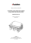
EXAMPLES OF TRAFFIC INFORMATION PICTOGRAMS
1
2
3
4
5
6
7
8
9
10
11
12
13
14
15
16
Accident
Traffic jam
Slippery conditions
Strong winds
Slow traffic
Fog
Road works
Danger
Parking possible
Bad weather
Slow traffic
Traffic problems in both directions
Road partially closed or narrowed
Vehicle travelling in the opposite direction
Restricted speed
Vehicle breakdown
83C-3
83C
ON-BOARD TELEMATICS SYSTEM
Operating principle
"Spring/
"Fall 2002/Winter "Spring/summer
Map CD-ROM that summer 2002"
2003" version
2003" version
version
covers the country
(2003-B)
(2003-A)
(2002-B)
83C
TMC locator table
finding software
version (2)
France
France (1)
yes
yes
yes
2000-1
Germany
Deutschland (1)
yes (100%)
yes (100%)
yes (100%)
1999-1
Great Britain
UK/Irish Republic
yes (100%)
yes (100%)
yes (100%)
Not applicable
Ireland
UK/Irish Republic
start
yes
yes
Not applicable
SWITZERLAND
Switzerland/
Osterreich
yes
yes (100%)
yes
2001-a
Austria
Switzerland/
Osterreich
yes
yes
yes (100%)
Fall/Winter 2001
Holland
Benelux
yes (100%)
yes (100%)
yes (100%)
1999-1
Spain
Espana/Portugal
yes
yes
yes
Fall/Winter 2001
Italy
Italy (1)
yes
yes
yes
2000-1
Belgium
Benelux
yes
yes
yes (100%)
1999-1
Luxembourg
Benelux
yes
yes
yes (100%)
Not applicable
Portugal
Espana/Portugal
yes
yes
yes
Not applicable
Sweden
Sweden/
Denmark
yes
yes
yes (100%)
Spring/Summer
2002
Denmark
Sweden/
Denmark
yes
yes
yes (100%)
Spring/Summer
2002
Finland
Scandinavia
no
no
start (Helsinki,
Tampere)
Not applicable
Norway
Scandinavia
no
no
Akershus and
∅stfold
Not applicable
Czech
Republic
Switzerland/
Osterreich
no
start (Prague
+ main roads)
2003-A + (Brno,
Plzen, Ostrava,
Karlovy Vary)
Not applicable
Slovakia
Switzerland/
Osterreich
no
no
start (Bratislava
and main roads)
Not applicable
Poland
---
no
no
no
Not applicable
Hungary
---
no
no
no
Not applicable
(1)
2 ()
The France/Germany/Italy border zones are available on the "Switzerland/Osterreich" CD-ROM.
The TMC locator tables enable drivers to receive traffic information if it is broadcast in the country concerned
(more specifically, they enable the broadcast events to be located on the map).
83C-4
ON-BOARD TELEMATICS SYSTEM
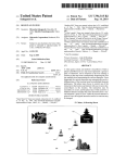
Description of the system
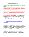
DIAGRAM
1
2
3
4
5
6
7
8
9
10
11
12
13
Central Communications Unit
Keyboard
Carminat computer (CD-ROM reader)
Screen
Seat belt information (for display)
External temperature information (for display)
Radio
Voice synthesiser speaker
Steering wheel radio control
Radio aerial
Radio connection (mute)
Vehicle's multiplex connection
Satellite aerial
83C-5
83C
ON-BOARD TELEMATICS SYSTEM
Description of the system
83C
WARNING
When replacing a navigation system component, it is essential to check that the software is compatible with the
navigation CD-ROM reader, the Central Communications Unit, and the languages CD-ROM.
System
software
version
Navigation CDCentral
ROM reader
Communications
Unit version read version read from
menus
from menus
2 "A"
SECOND
LABEL
nav: 0182
csb: 1.80 or 1.82
nav: 0196
csb: 1.80 or 1.82
Languages
CD-ROM
Application
Notes on Changes
2.5 (1)
03/2001
-
2.5 (1)
01/2003
2.4
2 TER (2)
●
new traffic information
messages
alternative route
suggestion
● new rotary knob
functions
●
3
3.63
nav: 0304
csb: 3.00
3 "A"
SECOND
LABEL
3.67
nav: 0350
csb: 3.00 or 3.01
3 TER
-
3
QUATTRO (2)
3.67
nav: 0376
csb: 3.00 or 3.01
All versions
CD-ROM
01/2003
4
4.51
nav: 0434
csb: 4.31 or 4.32
4.0 (1)
10/2002
4 BIS (2)
4.60
nav: 0457
csb: 4.31 or 4.32
All versions
CD-ROM
02/2003
4 TER
-
-
(1)
(2)
3.0 (1)
01/2002
3.5 (1)
-
-
-
-
never used
-
-
"NAV5 Languages All Versions CD" compatible.
Software upgrade using the "NAV5 Languages All Versions CD".
83C-6
04/2003
●
new traffic information
messages
●
screen watch
●
new traffic information
messages
●
restricted access
ON-BOARD TELEMATICS SYSTEM
Central Communications Unit
Depending on the vehicle, the Central
Communications Unit may have a keyboard.
The Central Communication Unit can:
● adjust the clock,
● act as a go-between for the vehicle's multiplex
network and the Carminat system network,
● use multiplex data (depending on the vehicle),
● select commands with the radio knob or keyboard
(depending on the vehicle equipment),
● control braking conditions, and the vehicle and
system configurations,
● control the screen display (with the navigation
CD-ROM reader),
● receive written or spoken messages from the traffic
information system (via the aerial)
● manage voice synthesiser and navigation
messages,
● transfer data from the radio for display.
83C-7
83C
ON-BOARD TELEMATICS SYSTEM
Central Communications Unit
CONNECTIONS
30-track connector (B) (grey):
Track
1
2
3
4
5
6
7
8
9
10
11
12
13
14
15
16
17
18
19
15-track connector (A) (red):
Track
1
2
3
4
5
6
7
8
9
10
11
12
13
14
15
83C
20
21
22
23
24
25
26
27
28
29
30
Description
Not used
Not used
Not used
Not used
Not used
Not used
Not used
Not used
Radio control satellite
Radio control satellite
Radio control satellite
Radio control satellite
Radio control satellite
Radio control satellite
Not used
83C-8
Description
Not used
Aerial amplifier output
Multiplex connection (multimedia)
Multiplex connection (multimedia)
Multiplex connection (multimedia)
Multiplex connection (multimedia)
Computer on-off output
Computer audio link
Computer audio link
Not used
Not used
Not used
Not used
Not used
Not used
Exterior temperature signal (input)
Exterior temperature signal (input)
Not used
Vehicle speed input (except multiplex
vehicle)
Reverse gear input (except multiplex
vehicle)
External temperature output
Not used
Not used
Seat belt warning light
+ Lighting
Radio display (low-end)
Radio ON/OFF
Radio display (low-end)
Radio display (low-end)
Radio display (low-end)
ON-BOARD TELEMATICS SYSTEM
Central Communications Unit
83C
30-track connector C (green):
Track
1
2
3
4
5
6
7
8
9
10
11
12
13
14
15
16
17
18
19
20
21
22
23
24
25
26
27
28
29
30
(D) and (E): radio aerial input and output
12-track connector (keyboard removed):
Track
1
2
3
4
5
6
7
8
9
10
11
12
Description
Left rotary knob
+ Lighting
Push-button
Push-button
Keyboard earth
Confirmation switch
Right rotary knob
+ rotary knob
Rotary knob earth
Keyboard earth
Push-button
Push-button
83C-9
Description
Not used
Not used
Not used
Not used
Not used
Multiplex connection (vehicle)
Multiplex connection (vehicle)
Not used
+ accessories
+ before ignition
Radio mute control
Earth
+ After ignition (except multiplexed
vehicle)
Voice synthesiser computer
Voice synthesiser computer
Not used
Not used
Not used
Not used
Not used
Not used
Speaker output
Speaker output
Not used
Not used
Not used
Not used
Not used
Not used
Not used
ON-BOARD TELEMATICS SYSTEM
Central Communications Unit
83C
CLIO II
Remove the Central Communications Unit using the
radio removal tools (Ms. 1373).
REMOVAL
The Central Communication Unit is located
underneath the front right-hand seat.
WARNING
Wait until the system has shut down completely
(1 minute) before disconnecting the battery.
Note:
It is not necessary to remove the seat.
Move the seat as far back as possible.
Remove the rear mounting bolt on the support and
raise the rear section.
REFITTING
Position the Central Communications Unit in its
mounting.
Connect the connectors.
Insert the front mounting guides into their housings.
Position the mounting and the mounting bolts.
Initialise the system (refer to the Initialisation
section).
Disconnect the connectors and remove the assembly.
83C-10
ON-BOARD TELEMATICS SYSTEM
Central Communications Unit
83C
MEGANE - SCENIC - SCENIC II
REMOVAL
Special notes on the Scénic and Scénic II
The Central Communication Unit is located
underneath the front right-hand seat.
WARNING
Wait until the system has shut down completely
(1 minute) before disconnecting the battery.
The Central Communication Unit is located in the
luggage compartment, above the CD ROM reader,
behind the cover.
Special notes on the Mégane
Remove the cover mounting bolts (1).
Remove the cover.
Note:
It is not necessary to remove the seat.
Remove the Central Communications Unit using the
radio removal tools (Ms. 1373).
REFITTING
Initialise the system (refer to the Initialisation
section).
83C-11
ON-BOARD TELEMATICS SYSTEM
Central Communications Unit
MEGANE II
REMOVAL
The Central Communications Unit is installed in the
dashboard. It incorporates the keyboard.
WARNING
Wait until the system has shut down completely
(1 minute) before disconnecting the battery.
Remove the Central Communications Unit using the
radio removal tools (Ms. 1373).
Disconnect the connectors and remove the assembly.
REFITTING
Connect the connectors.
Insert the guides into their positions.
Position the Central Communications Unit in its
mounting.
Initialise the system (refer to the Initialisation
section).
83C-12
83C
ON-BOARD TELEMATICS SYSTEM
Central Communications Unit
83C
LAGUNA II - TRAFIC II - AVANTIME
REMOVAL - REFITTING
Special notes on the Trafic II
The Central Communication Unit is located above the
radio.
WARNING
Wait until the system has shut down completely
(1 minute) before disconnecting the battery.
The Central Communication Unit is removed with the
radio removal tools (Ms. 1373).
After refitting, initialise the system (refer to the
Initialisation section).
Special notes on the Laguna II
The Central Communication Unit (1) is located above
the radio or CD ROM reader.
Special notes on the Avantime
The Central Communication Unit is located at the front
of the dashboard above the CD changer.
83C-13
ON-BOARD TELEMATICS SYSTEM
Central Communications Unit
VEL SATIS
REMOVAL
The Central Communication Unit is located behind the
cover, under the radio or CD changer.
WARNING
Wait until the system has shut down completely
(1 minute) before disconnecting the battery.
Removal is carried out using tool Ms. 1373.
REFITTING
Initialise the system (refer to the Initialisation
section).
83C-14
83C
ON-BOARD TELEMATICS SYSTEM
Central Communications Unit
ESPACE IV
REMOVAL
The Central Communications Unit is located in the
front left glovebox.
Removal is carried out using tool Ms. 1373.
REFITTING
Initialise the system (refer to the Initialisation
section).
83C-15
83C
ON-BOARD TELEMATICS SYSTEM
Keyboard
The keyboard may be integrated into the Central
Communication Unit or independent, depending on the
vehicle.
It comprises:
●
●
●
●
●
●
a rotary knob (A) for:
– navigating the various menus,
– confirming,
a navigation cell (B) for:
– scrolling through the menu in manual mode,
– select options in the different menus,
a menu button (M) (depending on the vehicle) for
returning to the main menu,
a button (I) for replaying voice messages,
a button (C) for turning off voice messages,
buttons (+) and (-) which increase and reduce the
volume of audio messages.
83C-16
83C
ON-BOARD TELEMATICS SYSTEM
Keyboard
83C
ESPACE IV - CLIO II - MEGANE - SCENIC - SCENIC II
The independent keyboard is connected to the Central
Communication Unit by a special 12-track connector.
Special notes on the Mégane and Scénic
The keyboard is clipped below the screen.
Note:
Only the feeds and earths can be checked.
It is necessary to remove the upper section of the
dashboard and the screen to reach the connector.
CONNECTION
Special notes on Clio II, Scénic II and Espace IV
Track
Track
1
2
3
4
5
6
7
8
9
10
11
12
A1
A2
A3
A4
A5
A6
A7
A8
A9
B1
B2
B3
B4
B5
B6
B7
B8
B9
Description
Rotary knob at left
+ Lighting
Push-button
Push-button
Keyboard earth
Confirmation switch
Rotary knob at right
+ rotary knob
Rotary knob earth
Keyboard earth
Push-button
Push-button
83C-17
Description
Rotary knob
Rotary knob
Rotary knob
Rotary knob
Not used
Not used
Not used
Keyboard keys
Keyboard keys
Keyboard keys
Keyboard keys
Keyboard lighting supply
Keyboard lighting earth
Not used
Not used
Not used
Not used
Not used
ON-BOARD TELEMATICS SYSTEM
Navigation CD-ROM reader
The navigation CD-ROM reader works by using
sensors that detect vehicular motion. The car's
tachometric (or ABS) sensor calculates the distance
travelled while the gyroscope registers turns.
By making comparisons with the digital map (on the
CD-ROM), the system corrects inaccuracies (tyre
pressure and wear, temperature etc.) to pinpoint the
vehicle's location.
IMPORTANT
If the battery has been disconnected or the
navigation computer replaced, relocation of the
vehicle is automatic (refer to the Relocation
section).
The system will be programmed in French by default
after the navigation CD-ROM reader has been
replaced.
To change language, see Language Settings.
WARNING
When the navigation CD-ROM reader is replaced,
the addresses stored in the old unit cannot be
recovered.
83C-18
83C
Note:
– With the ignition off, the CD-ROM player lights up
automatically when the eject button is pressed
and will remain lit for about 1 minute (if the ignition
is not switched back on).
– The player lights up automatically when the
ignition is turned on.
– After the ignition is turned off, it remains lit for
approximately 1 minute, during which time the
battery must not be disconnected.
– The navigation CD-ROM readers differ,
depending on whether installed horizontally or
vertically.
ON-BOARD TELEMATICS SYSTEM
Navigation CD-ROM reader
16-track connector (3) to the display:
CONNECTIONS
Track
1
2
3
4
5
6
7
8
9
10
11
12
13
14
15
16
(1) Satellite aerial connection
18-track connector (2) to the vehicle:
Track
1
2
3
4
5
6
7
8
9
10
11
12
13
14
15
16
17
18
83C
Description
+ Before ignition
Not used
Central Communication Unit audio link
Not used
Not used
Computer on-off input
Not used
Not used
Multiplex connection (multimedia)
Earth
Not used
Central Communication Unit audio link
Not used
Not used
Vehicle speed signal
Not used
Not used
Multiplex connection (multimedia)
83C-19
Description
Not used
Earth
- Video signal
Red video signal
Green video signal
Blue video signal
Earth
Video synchronisation signal
Earth
Brightness adjustment
Not used
Screen on/off
Not used
Not used
+ Before ignition
+ Before ignition
ON-BOARD TELEMATICS SYSTEM
Navigation CD-ROM reader
83C
CLIO II - TRAFIC II
REMOVAL - REFITTING
Special notes on the Trafic II
The navigation CD-ROM reader is in the lower section
of the dashboard.
WARNING
Wait until the system has shut down completely
(1 minute) before disconnecting the battery.
It is removed with the radio removal tools (Ms. 1373).
WARNING
The satellite aerial wire is very fragile. Do not bend
or trap it.
After refitting, initialise the system (refer to the
Initialisation section).
Special notes for Clio II
The navigation CD-ROM reader is in the luggage
compartment (left side).
It is removed with the radio removal tools (Ms. 1373).
83C-20
ON-BOARD TELEMATICS SYSTEM
Navigation CD-ROM reader
83C
SCENIC
Remove:
– both support mounting bolts on the casing.
REMOVAL
The navigation CD-ROM reader is under the Central
Communications Unit below the right front seat.
WARNING
Wait until the system has shut down completely
(1 minute) before disconnecting the battery.
Note:
It is not necessary to remove the seat.
Move the seat as far back as possible.
Remove the compartment mounting bolts and unclip it.
Remove:
– the computer using tools Ms. 1373.
Pull the assembly forwards and disconnect the
connectors.
WARNING
The satellite aerial wire is very fragile. Do not bend
or trap it.
REFITTING
Proceed in the reverse order to removal.
After refitting, initialise the system (refer to the
Initialisation section).
83C-21
ON-BOARD TELEMATICS SYSTEM
Navigation CD-ROM reader
83C
MEGANE II
REFITTING
WARNING
Wait until the system has shut down completely
(1 minute) before disconnecting the battery.
Insert the guides into their positions.
Connect the connectors.
REMOVAL
Place the navigation CD-ROM reader in its mounting.
The navigation CD-ROM reader is located in the
luggage compartment, next to the amplifier, behind the
cover.
Initialise the system (refer to the Initialisation
section).
Remove the cover clipped to the carpet.
Remove the CD-ROM reader with the radio removal
tools (Ms. 1373)
Disconnect the connectors and remove the assembly.
WARNING
The satellite aerial wire is very fragile. Do not bend
or trap it.
83C-22
ON-BOARD TELEMATICS SYSTEM
Navigation CD-ROM reader
83C
LAGUNA II
Detach the support from the computer using the radio
removal tools (Ms. 1373).
REMOVAL
WARNING
Wait until the system has completely shut down
(1 minute) before disconnecting the battery.
Remove:
– the glove compartment cover secured by a screw,
– the computer support mounting bolts.
Disconnect the navigation CD-ROM reader connectors
and lower the unit.
WARNING
The satellite aerial wire is very fragile. Do not bend
or trap it.
REFITTING
Proceed in the reverse order to removal.
After refitting, initialise the system (refer to the
Initialisation section).
83C-23
ON-BOARD TELEMATICS SYSTEM
Navigation CD-ROM reader
83C
MEGANE - AVANTIME - SCENIC II
REMOVAL - REFITTING
Special notes on the Avantime
The navigation CD-ROM reader is located in the
glovebox (passenger's side).
WARNING
Wait until the system has completely shut down
(1 minute) before disconnecting the battery.
It is removed with the radio removal tools (Ms. 1373).
WARNING
The satellite aerial wire is very fragile. Do not bend
or trap it.
After refitting, initialise the system (refer to the
Initialisation section).
Special notes on the Mégane
The navigation CD-ROM reader is in the luggage
compartment (left side).
It is removed with the radio removal tools (Ms. 1373).
Special notes on the Scénic II
The navigation CD-ROM reader is located underneath
the right front seat.
It is removed with the radio removal tools (Ms. 1373).
Note:
It is not necessary to remove the seat.
83C-24
ON-BOARD TELEMATICS SYSTEM
Navigation CD-ROM reader
VEL SATIS
REMOVAL
The navigation CD-ROM reader is located in the
glovebox.
WARNING
Wait until the system has completely shut down
(1 minute) before disconnecting the battery.
Removal is carried out using tool Ms. 1373.
REFITTING
Initialise the system (refer to the Initialisation
section).
83C-25
83C
ON-BOARD TELEMATICS SYSTEM
Navigation CD-ROM reader
ESPACE IV
REMOVAL
The navigation CD-ROM reader is located in the
glovebox.
Removal is carried out using tool Ms. 1373.
REFITTING
Initialise the system (refer to the Initialisation
section).
83C-26
83C
ON-BOARD TELEMATICS SYSTEM
Screen
Special notes on the radio (depending on the
vehicle)
The screen can display:
– the various menus,
– the destination direction,
– the distance from the destination,
– the journey maps,
– the distance remaining until the next change of
direction,
– the road maps,
– etc.
If the vehicle is fitted with an original radio, the display
will appear on the screen bar (radio on only).
When the radio is being adjusted, the radio display fills
the screen (for greater visibility) in list or preset mode.
It lights up a few seconds after +accessories is
switched on or the radio is switched on and displays
the security message.
It goes out approximately 45 seconds after the ignition
is switched off.
5
6
7
8
9
Note:
If the radio information does not appear on screen,
refer to the "Initialisation" section.
Special notes on the clock
The clock is connected to the satellite link (GPS). The
reference time is adjusted manually via the Clock
menu, but the satellite connection allows precise
adjustment.
Note:
The screen colour and brightness can be adjusted
using the Screen configuration menu:
– daytime blue or dark blue (side lights).
– night time blue or dark blue (side lights on).
1
2
3
4
83C
WARNING
Do not use cleaning products to clean the screen. It
should be wiped with a soft, dry cloth or a damp
cloth.
Time
External temperature
Traffic Information message pictogram
Time of arrival or journey remaining (can be
configured)
Guidance mode pictogram
Disc present pictogram
Satellite reception quality pictogram
Radio display (depending on the vehicle)
Tyre pressure monitor and opening elements
(depending on the vehicle)
83C-27
ON-BOARD TELEMATICS SYSTEM
Screen
83C
DISPLAY
Time
Seat belt
Radio Temperature
indicator
Tyre indicator
Tyre location
Opening
element
warning
light
Opening
element
location
Clio II
X
X
X
-
-
-
-
-
Mégane
(XAXX)
-
-
-
-
X (1)
X (1)
X (1)
X (1)
Scénic
(JAXX)
X
X
X
-
X (1)
X (1)
X (1)
X (1)
Mégane II
(XMXX)
X
X
X
-
-
-
-
-
Scénic II
(JMOX)
X
X
X
-
-
-
-
-
Laguna II
X
X
X
X
X
X
X
X
Vel Satis
-
X
X
X
X
-
X
-
Espace IV
-
X
-
-
-
-
-
-
Avantime
-
-
-
-
-
-
-
-
1
Vehicles fitted with the Tyre Pressure Monitoring System
83C-28
ON-BOARD TELEMATICS SYSTEM
Screen
CONNECTIONS
Track
1
2
3
4
5
6
7
8
9
10
11
12
13
14
15
16
Screening
Description
Not used
Earth
- Video signal
Red video signal
Green video signal
Blue video signal
Earth
Video synchronisation signal
Earth
Brightness adjustment
Not used
Screen on/off
Not used
Not used
+ Before ignition
+ Before ignition
Earth screen
83C-29
83C
ON-BOARD TELEMATICS SYSTEM
Screen
CLIO II
Remove:
– the trim strips,
– the dashboard mounting bolts.
REMOVAL - REFITTING
With the ignition switched off, position the steering
column to a low setting.
Unclip and disconnect the control keyboard (1).
Remove:
– the steering wheel casing mounting bolts,
– the steering wheel upper cowling,
– the bolts.
Remove:
– the upper section of the dashboard,
– the screen and its mounting.
83C-30
83C
ON-BOARD TELEMATICS SYSTEM
Screen
83C
MEGANE - SCENIC
Remove:
– the speaker grilles,
– the upper section of the dashboard,
– the screen mounting bolts (3).
REMOVAL - REFITTING
With the ignition switched off, position the steering
column to a low setting.
Disconnect the screen and the keyboard.
Unclip the CARMINAT speaker support (1) and the
control keyboard (2).
Separate the screen from its mounting by removing
the screws (4).
21111
83C-31
ON-BOARD TELEMATICS SYSTEM
Screen
83C
TRAFIC II
Swivel the screen, taking care not to scratch the
dashboard.
REMOVAL - REFITTING
With the ignition off, remove:
– the Central Communication Unit using the Ms. 1373
tools.
Open the protective housing.
Remove:
– the screen mounting bolts.
Pull out the screen to unclip it from the dashboard.
Disconnect the connector by pressing on the bolt.
Separate the screen from its mounting by removing
the screws.
83C-32
ON-BOARD TELEMATICS SYSTEM
Screen
83C
SCENIC II
REMOVAL - REFITTING
Removing the navigation screen requires removing the
instrument panel.
Disconnect the battery.
Remove the mounting bolts (3).
Remove the instrument panel.
Unclip the trim (1) with the tool (Car. 1597).
Remove the screen mounting bolts (4).
Unclip the instrument panel rim (2).
Remove the screen.
83C-33
ON-BOARD TELEMATICS SYSTEM
Screen
83C
LAGUNA II
Disconnect the connection with the computer.
REMOVAL - REFITTING
With the ignition off, remove:
– the two covers either side of the screen,
– the mounting bolts (1),
– the underside of the screen by unclipping it (2).
Remove the screen mounting bolts to detach it from
the support.
83C-34
ON-BOARD TELEMATICS SYSTEM
Screen
83C
MEGANE II
Disconnect the connectors.
SCREEN AND CENTRAL DISPLAY UNIT
REMOVAL
The screen and the Central Display Unit are in one
piece.
Unclip the upper section (A) of the dashboard.
REFITTING
Proceed in the reverse order to removal.
Initialise the system (refer to the Initialisation
section).
Disconnect the sunlight sensor (B).
Remove the four screws (C).
83C-35
ON-BOARD TELEMATICS SYSTEM
Screen
MEGANE II
CENTRAL DISPLAY UNIT CONNECTIONS
Track
1
2
3
4
5
6
7
8
9
10
11
12
13
14
15
16
17
18
Description
+ Before ignition
Not used
Not used
Not used
Not used
Not used
Earth
Not used
+ Lighting
Not used
Not used
Not used
Multimedia multiplex link to screen
Multimedia multiplex link to screen
Multimedia multiplex link to Central
Communications Unit
Multimedia multiplex link to Central
Communications Unit
On/off input to Central
Communications Unit
On/off input to screen
Note:
The screen connections are the same as in other
vehicles.
83C-36
83C
ON-BOARD TELEMATICS SYSTEM
Screen
83C
AVANTIME
REMOVAL
Disconnect the connector.
Open the glovebox and remove the mounting bolts (A)
from the screen mounting.
Remove the screen mounting bolts (C).
Pull out the assembly to the whole length of the wire
so that it can be put back.
REFITTING
It is essential to respect the position of the screws
according to their length.
Remove the mounting screws (B).
83C-37
ON-BOARD TELEMATICS SYSTEM
Screen
83C
VEL SATIS
REMOVAL - REFITTING
The instrument panel must be removed to remove the
screen.
Remove the upper instrument panel trim clipped to the
dashboard.
Remove:
– the lower instrument panel trim clipped to the
dashboard,
83C-38
Remove:
– the instrument panel mounting bolts.
– the screen mounting bolts on the instrument panel.
ON-BOARD TELEMATICS SYSTEM
Screen
83C
ESPACE IV
Disconnect the connectors (F)
REMOVAL - REFITTING
Using a flat screwdriver, unclip the cover.
Remove the two screen mounting screws (D).
With a screwdriver, remove the clips (A) on each side
of the screen.
Take out the screen mounting.
83C-39
ON-BOARD TELEMATICS SYSTEM
Screen
ESPACE IV
Note:
The screen mounting has a switch (B) that turns off
the display when the dashboard cover is closed.
83C-40
83C
ON-BOARD TELEMATICS SYSTEM
Aerial
The satellite aerial
It picks up satellite signals so that the electronic
navigation computer (CD-ROM player) can locate the
position of the vehicle.
When the satellite reception is good, a green
pictogram (1) is displayed on screen.
When the satellite reception is poor (caused by going
through a tunnel or along a street surrounded by tall
buildings, etc.), a red pictogram is displayed on
screen.
Note:
Relocation is automatic once the battery has been
reconnected or the navigation computer has been
replaced: drive the vehicle to an outdoor open area
with the ignition off and wait a few minutes. When the
satellite reception is good, a green pictogram is
displayed on screen.
WARNING
The satellite aerial wire is very fragile. Do not bend
or trap it.
Note:
The satellite aerial is also used for the hands-free
phone. Some vehicles are fitted with a dual band
aerial.
83C-41
83C
ON-BOARD TELEMATICS SYSTEM
Aerial
83C
CLIO II
Disconnect the aerial wires.
REMOVAL - REFITTING
The aerial is fitted on the roof. The headlining and boot
lining (right-hand side) must be partially removed to
remove the aerial.
WARNING
The satellite aerial wire is very fragile. Do not bend
or trap it.
Note:
The satellite aerial incorporates the radio aerial and
the telephone aerial (dual band).
Remove:
– the mounting bolts on the rear parcel shelf (3),
– the parcel shelf support,
– the linings (1) and (2).
Remove:
– the headlining (partially),
– the mounting nut, then remove the aerial.
83C-42
ON-BOARD TELEMATICS SYSTEM
Aerial
TRAFIC II
REMOVAL - REFITTING
The aerial is fitted on the roof. The headlining must be
partially removed to remove the aerial.
WARNING
The satellite aerial wire is very fragile. Do not bend
or trap it.
83C-43
83C
ON-BOARD TELEMATICS SYSTEM
Aerial
83C
MEGANE - SCENIC
Special notes on the Scénic
The aerial is located on the plenum chamber plate,
underneath the engine cover.
Remove:
– the windscreen wiper arms,
– the plenum chamber half-grilles.
WARNING
The satellite aerial wire is very fragile. Do not bend
or trap it.
REMOVAL - REFITTING
Special notes on the Mégane
The aerial (1) is located underneath the rear parcel
shelf support (left-hand side).
Removing it requires removing the CD-ROM reader
with the tool (Ms. 1373) as well as its mounting.
83C-44
Disconnect the wire and detach the aerial.
ON-BOARD TELEMATICS SYSTEM
Aerial
MEGANE II - SCENIC II
REMOVAL - REFITTING
The aerial is fitted on the roof. Removing it requires
part of the head lining to be removed (see Bodywork
section).
Note:
The satellite aerial incorporates the radio aerial, the
amplifier and the telephone aerial (dual band).
Remove the marker nut (D) and disconnect
connectors (E) and (F).
83C-45
83C
ON-BOARD TELEMATICS SYSTEM
Aerial
83C
LAGUNA II
Special notes on the Laguna II
DUAL BAND AERIAL
First-generation Laguna II's are fitted with a satellite
aerial and a mono-band telephone. These aerials have
been replaced by dual-band satellite and telephone
aerials. They are visible on the rear section of the roof.
The aerial is fitted on the roof. The head lining and rear
right-hand quarter panel must be partially removed to
remove the aerial.
MONO-BAND AERIAL
Remove the upper tailgate lining.
Disconnect the aerial connectors (B).
Remove the mounting nuts (C) and then the satellite
aerial (A).
83C-46
ON-BOARD TELEMATICS SYSTEM
Aerial
VEL SATIS - ESPACE IV
DUAL BAND AERIAL
The aerial is fitted on the roof. Removing it requires
partial removal of the headlining and rear right quarter
trim (see Bodywork manual).
The aerial wire is connected to the switch plate (2)
(e.g. Vel Satis).
83C-47
83C
ON-BOARD TELEMATICS SYSTEM
Aerial
83C
AVANTIME
REMOVAL
REFITTING
Lock the airbag computer using a fault finding tool.
Slide the satellite aerial into its housing.
Disconnect the battery.
Reposition the aerial wire along its original route and
reconnect it.
Remove:
– the driver's seat,
– the central keyboard.
Refit:
– the soundproofing,
– the carpet,
– the door seal,
– the central keyboard soundproofing material,
– the driver's seat.
Remove the soundproofing material on the central
keyboard tunnel,
Cut the carpet in the middle of the central keyboard in
front of the gear lever,
Reconnect the battery.
Unlock the air bag computer and carry out fault finding.
Disconnect the satellite aerial wire at the threaded
union.
Detach the carpet and soundproofing (driver's side),
Remove the satellite aerial sensor (A) from its housing
by sliding it towards the centre of the roof,
83C-48
ON-BOARD TELEMATICS SYSTEM
Speaker
The navigation system can use:
– a special speaker,
– the voice synthesiser speaker (the Central
Communication Unit regulates the messages from
the voice synthesiser),
– a radio speaker.
83C
Special notes for Clio II
The special system speaker (2) is located beneath the
heating control panel. The central keyboard
compartment needs to be removed to remove the
speaker.
Special notes on the Mégane and Scénic
The special system speaker (1) is located beneath the
upper section of the dashboard.
Special notes on the Laguna II and Vel Satis
The speaker (3) is positioned in place of the voice
synthesiser speaker.
83C-49
ON-BOARD TELEMATICS SYSTEM
Speaker
Special notes on the Trafic II
83C
Note:
To remove it, unclip the upper section of the
instrument panel (see Workshop Repair
Manual 364).
The speaker used for the navigation system is the
front right-hand radio speaker.
Special notes on the Avantime
Special notes on the Scénic II
The special system speaker (4) is positioned near to
the central keyboard light.
To remove the speaker, remove the lower trim from the
dashboard.
Special notes on the Mégane II
The special system speaker (A) is located beneath the
upper section of the dashboard.
83C-50
ON-BOARD TELEMATICS SYSTEM
Speaker
Special notes on the Espace IV
Vehicle with voice synthesiser.
The navigation speaker (1) is the same as the voice
synthesiser one if the vehicle is equipped with both
features.
Messages are controlled by the Central
Communications Unit.
Vehicle without voice synthesiser.
The navigation speaker (1) is under the dashboard on
the driver's side.
83C-51
83C
ON-BOARD TELEMATICS SYSTEM
Initialisation
INITIALIZATION
83C
INITIALIZATION
This procedure must be followed every time a part is
replaced.
WARNING
If the vehicle is fitted with a radio, it must be switched
on during initialisation. If it is not, the steering wheel
radio control will not function and the screen will not
display radio data.
1
2
Switch off the ignition,
Wait until the system completely shuts down
(about 1 minute).
3 Switch the radio on,
4 Switch on the ignition (wait approximately
20 seconds),
5 Press the buttons simultaneously (see table).
6 Read the vehicle part number (refer to the table).
7 Carry out the steering wheel control test,
8 The satellite aerial connection (connected / not
connected to GPS) appears on the screen,
9 Ignore radio aerial and telephone tests,
10 Exit setting using the rotary switch,
11 Switch off the ignition (1 minute).
Note:
If the configuration does not correspond to the
vehicle, check the vehicle wiring (multiplex lines)
and the part numbers of the components.
83C-52
Vehicles
Keys
Clio II:
Trafic II
Mégane and Scénic
Mégane II
Scénic II
Laguna II
Vel Satis
Avantime
Espace IV
M and C
M and C
"−" and "→"
M and C
M and C
M and C
M and C
M and C
M and C
System configurations
Vehicles
Clio II:
Trafic II
Mégane and Scénic
Mégane II
Scénic II
Laguna II
Vel Satis
Avantime
Espace IV
without Entry level
radio
radio
0312
0612
1612
1312
1412
0012
0412
-
0302
0602
1602
1326
1402
0002
0102
0207
Top of the
range
radio
1327
1407
0007
0107
0217
ON-BOARD TELEMATICS SYSTEM
Upgrading the Navigation CD-ROM reader software
10 Wait approximately 2 minutes. A progress bar
appears. It enables you to track the progress of the
software upgrade.
Upgrading the navigation CD-ROM reader software
takes about 5 minutes.
If the CD-ROM is ejected during installation, carefully
clean it, then reinsert it into the reader. The system will
restart automatically.
1
Switch on the ignition without starting the engine.
WARNING
Do not switch off the ignition during this operation or
the navigation system will become unusable.
2
3
4
5
6
7
Select OK on the Navigation system welcome
screen.
Select Navigation from the main menu.
Eject the map CD-ROM by pressing the Eject
button on the front of the CD-ROM reader. See the
Navigation Assistance Technical Note for the
location of the parts.
Insert the CD-ROM labelled Languages CD Nav5 All Versions.
Once the CD-ROM has been detected (which
takes a few seconds), the system asks: "Install
software?".
Select Yes if the current version displayed and
new version differ.
Note:
If both versions are identical, select No: the system
already has the new software. The system then
automatically ejects the Languages CD - Nav5 All
Versions. Insert the map CD-ROM into the reader.
8
9
83C
A wait message is then displayed for about
15 seconds before the screen goes black.
After about 10 seconds, the system indicates it will
update the software ("The installation program
will update your system").
83C-53
Note:
The "progress bar" may remain at 100% for a few
seconds. This is normal system operation.
11 Once the upgrade is finished, the system
automatically ejects the "Languages CD - Nav5
All Versions".
12 The system then reboots with a message: "The
system will reboot now".
13 The screen goes black and the RENAULT logo
appears.
14 Next the system displays the "Navigation" menu.
15 The system upgrade is now completed. Insert the
map CD-ROM into the reader.
Note:
The "Languages CD - Nav5 All Versions" must be
used instead of the old one to install new languages
into the system.
ON-BOARD TELEMATICS SYSTEM
Changing language
The system will be programmed in French by default
after the navigation computer has been replaced.
●
1
Change menus language
With the ignition switched on, press the eject
button to remove the electronic navigation
computer cartographic CD-ROM
2
The screen will display the message No CD in
reader.
3
Confirm OK by pressing the rotary knob.
4
Select the Language menu.
Change voice messages
1
With the ignition switched on, press the eject
button to remove the electronic navigation
computer cartographic CD-ROM
2
The screen will display the message No CD in
reader.
3
Confirm OK by pressing the rotary knob.
4
Select the * Configurations menu then
Language.
You must carry out these two operations to change the
language:
●
83C
Note:
If the desired language does not appear in the menu,
do the following:
83C-54
1
Select other language.
2
The system prompts you to insert the language
CD-ROM.
3
Insert the CD-ROM, and then press the rotary
knob to confirm.
4
Select the language to be replaced (language 1 or
2) by turning the knob.
5
Use the rotary knob to select the language to load
from the list of available languages stored on the
CD-ROM and then confirm load.
6
Wait a few seconds. The screen will turn black and
then white and display a message in black and red
with a horizontal bar to show the loading time
remaining.
7
When loading is complete, the language CD-ROM
is ejected from the reader and OK is displayed on
screen.
8
Continue with voice message changing procedure.
9
Reinsert the cartographic CD-ROM into the
reader.
ON-BOARD TELEMATICS SYSTEM
Changing language
83C
Country languages available in the
system
Country languages available in
the manual
French
yes
yes
German
yes
yes
English (GB)
yes
yes
English (USA)
yes
NO
Dutch
yes
yes
Spanish
yes
yes
Italian
yes
yes
Swedish
yes (except system menus)
NO
Danish
yes (except system menus)
NO
Portuguese
NO
NO
Czech
NO
NO
Slovak
NO
NO
83C-55
ON-BOARD TELEMATICS SYSTEM
Relocation
The vehicle has to be relocated after the electronic
navigation computer has been replaced or the battery
disconnected.
Drive the vehicle to an open area outdoors and wait for
a few minutes with the ignition switched on.
When the satellite reception is good, a green
pictogram (1) is displayed on screen.
If the vehicle is not correctly located on the map, drive
the vehicle to along various main roads on the mapped
routes (0.6 to 1.8 miles (1 to 3 km) necessary).
Note:
The localisation operation may take up to
20 minutes maximum.
83C-56
83C
ON-BOARD TELEMATICS SYSTEM
Navigation menus
83C
Welcome message
Navigation
–
–
–
–
–
–
Adjustments
Language *
guidance
map
address book
monitor
emergency
configuration
Monitor *
Change voice
messages
language
Clock
System
Adjusting the set
time
(Expert mode)
Code: 4112
System test
Keyboard Test
Config
Bus Test
– CAN V
– CAN M
– IIC
satellite
– configuration
– Central Communications
Unit type
– software
version
– date of
manufacture
– 12 NC
– checksum
keyboard
* depending on the version
83C-57
Functions test
RDS/TMC
Vehicle
– frequency
– reception level
– RDS quality:
– Speed
– + after ignition
feed
– + ACC
– tyre pressure
monitor
– battery
voltage
– seat belt
– + light
– reverse gear
– external
temperature
ON-BOARD TELEMATICS SYSTEM
Navigation menus
83C
Welcome message
Adjustments
Guidance
Language
Navigation
Address
book
Card
Guidance
modes
Changing
the menu
language
Screen
config
–
–
–
–
–
Configuration
Traffic
information
sensor status
longitude
latitude
geographical height
number of satellites
Emergency
System
information
Monitor
Units
Volume
– SDVC
– voice
messages
– volume
Configuration
–
–
–
–
–
–
(Code)
4112
–
–
–
–
–
Monitor *
day colour
state line
card colour
night colour
brightness
adjustment
Fault finding
Read GPS
data
Language *
–
–
–
–
–
Preadjustments
series number
product model
software version
week of manufacture
year of manufacture
CBS software
version
Read I/O
states
Read errors
Speed
correction
tachograph pulse
internal temperature
battery
injection button
steering
* depending on the version
83C-58
Simulation
– usable simulation
– unusable simulation
Restricted
access *
ON-BOARD TELEMATICS
183C SYSTEM
Customer complaints
83C
SCREEN DOES NOT OPEN
CHART 1
INCORRECT SCREEN ANGLE OR SCREEN FREEZES
CHART 2
THE SCREEN STAYS
BLACK
CHART 3
SCREEN IS BACKLIT OR FROZEN ON THE RENAULT LOGO
CHART 4
SCREEN DISPLAY FROZEN
CHART 5
SCREEN DISPLAYS "CONFIGURATION ERROR"
CHART 6
NO RADIO DISPLAY ON THE CARMINAT SCREEN (OR THE RADIO DISPLAY
REMAINS FROZEN)
CHART 7
WRONG TIME DISPLAYED
CHART 8
NO CLOCK DISPLAY
CHART 9
NO TYRE PRESSURE SYSTEM DISPLAY
CHART 10
TYRE PRESSURE MONITORING SYSTEM DATA DISPLAYED ON VEHICLE WITHOUT
IT
CHART 11
NO OPENING ELEMENT SYMBOL DISPLAY
CHART 12
NO SEAT BELT WARNING LIGHT DISPLAY
CHART 13
NO VOICE MESSAGES
CHART 14
NO TRAFFIC INFORMATION MESSAGE ON THE
SCREEN
CHART 15
POOR SATELLITE RECEPTION
CHART 16
NO RADIO DATA ON THE INSTRUMENT PANEL (OR RADIO DATA NOT REFRESHED)
CHART 17
TIME AND TEMPERATURE DATA ON INSTRUMENT PANEL AND NAVIGATION
SCREEN NOT THE SAME
CHART 18
IF THE VEHICLE JUMPS AROUND THE MAP DURING GUIDANCE, THE SYSTEM IS
DOING FREQUENT CALCULATIONS OR THE GUIDANCE IS FAULTY
CHART 19
83C-59
ON-BOARD TELEMATICS SYSTEM
Fault finding chart
83C
MEGANE II
CHART 1
Screen does not open
Check whether the screen opens
manually. Press the "ON/OFF"
button in front of the screen.
no
Does the screen open?
yes
Switch on the lights. Check that the
indicator lights on the keys in front of
the screen light up.
Do the indicator lights
come on?
no
Check the Central Display Unit
power supply (tracks 1 and 9)
and earth (track 7).
yes
Switch of the ignition for 1 minute.
Switch on the ignition and, without
pressing the "eject" button, check
that the CD-ROM drive indicator
light comes on.
Does the indicator
light come on?
yes
It is a mechanical fault or an endstop programming fault. Disconnect
and reconnect the battery. If the
problem persists, replace the
Central Display Unit after obtaining
authorization from Techline.
83C-60
no
Check the power supply
(ignition off = 0 V;
ignition on = 12 V):
– to the Central
Communications Unit on
track 7,
– to the navigation CD-ROM
reader on track 6,
– to the Central Display Unit on
tracks 17 et 18.
ON-BOARD TELEMATICS SYSTEM
"Top of the Range" navigation system: Fault finding charts
83C
MEGANE II
CHART 1
(continued)
Check whether the screen opens
automatically. Press the "ON/OFF"
button to close the screen, or press
on the rotary knob.
no
Does the screen open?
yes
Check the multiplex link
(multimedia):
– between the Central
Communications Unit and the
Central Display Unit,
– between the Central Display Unit
and the navigation CD-ROM
reader.
Refer to the "Wiring diagrams"
Technical Note.
Are the connections
correct?
no
yes
Repair the wiring. Check the other
navigation system functions.
Activate the screen display several
times. The problem may be due to a
hard point in the Central Display
Unit. If the problem persists, replace
the Central Display Unit after
obtaining authorization from
Techline.
83C-61
ON-BOARD TELEMATICS SYSTEM
"Top of the Range" navigation system: Fault finding charts
MEGANE II
CHART 2
Incorrect screen angle or screen freezes
Incorrect screen angle or screen freezes.
Press the screen "ON/OFF" button.
Disconnect and reconnect the battery to reset the
Central Display Unit and reprogram the end stops.
Press the screen "ON/OFF" button.
If the problem persists, replace the Central Display
Unit after obtaining authorization from Techline.
83C-62
83C
ON-BOARD TELEMATICS SYSTEM
"Top of the Range" navigation system: Fault finding charts
CHART 3
83C
Screen stays black (not lit up)
Check the navigation CD-ROM
reader's power supply. Switch the
ignition off for more than 1 minute,
then press the eject button.
Does the red light
come on?
no
yes
Check the green connector on the
navigation CD-ROM reader:
– + 12 V feed (track 1),
– the earth (track 9).
Check the Central
Communications Unit power
supply. Turn the ignition on and
switch on the lighting.
no
Did it pass the tests?
yes
Check the power fuse and wiring
(see the "Wiring Diagrams"
Technical Note).
Does the Central
Communication Unit
light up?
Replace the navigation CD-ROM
reader after obtaining authorisation
from Techline.
Test the green connector on the Central
Communications Unit:
– + 12 V feed (track 10),
– + accessories feed (track 9),
– the earth (track 12).
no
yes
no
Did it pass the tests?
yes
Check the power fuse and wiring
(see the "Wiring Diagrams"
Technical Note).
83C-63
Replace the Central
Communications Unit after
obtaining authorisation from
Techline.
ON-BOARD TELEMATICS SYSTEM
"Top of the Range" navigation system: Fault finding charts
83C
CHART 3
(continued)
Check the connection between
the Central Communications Unit
and the navigation CD-ROM
reader. Switch the ignition off for
more than 1 minute, then switch it
on again. The navigation CD-ROM
reader's red light should come on.
no
Does the red light
come on?
Check the navigation CD-ROM reader's power
supply (track 6) on the Central Communications
Unit grey connector (track 7):
– ignition off = 0 V,
– ignition on = 12 V.
yes
no
Check the connection between
the navigation CD-ROM reader
and the screen:
– + 12 V feed (tracks 15 and 16)
– earth (tracks 2 and 9),
– alarm feed (track 12) (on = 12 V off = 0 V).
no
Did it pass the tests?
yes
Check the wiring between the
Central Communications Unit, Central
Display Unit, and navigation CD-ROM
reader.
If the wiring is okay, replace the
navigation CD-ROM reader after
obtaining authorisation from Techline.
Did it pass the tests?
yes
If the wiring is okay, replace the
screen after obtaining authorisation
from Techline.
If the wiring is okay, replace the
navigation CD-ROM reader after
obtaining authorisation from
Techline.
83C-64
Replace the Central Display
Unit after obtaining
authorisation from Techline.
ON-BOARD TELEMATICS SYSTEM
"Top of the Range" navigation system: Fault finding charts
CHART 4
83C
Screen blank or frozen on RENAULT logo
Check the software compatibility
between the components.
Switch on the ignition, check if the
keyboard flashes.
Is the keyboard
flashing?
no
The system has not been
configured. Initialise the system
(refer to the Initialisation section).
yes
The vehicle has a problem with
an incompatible Central
Communications Unit and
navigation CD-ROM reader. Check
the part numbers in the Spare Parts
Catalogue (contact Techline).
no
Does the screen
display the
configurations?
yes
Check the multimedia multiplex
connections between the Central
Communications Unit, Central
Display Unit, radio amp/tuner and
navigation CD-ROM reader.
83C-65
Turn off the system (1 minute). The
problem disappears. Check the
overall operation of the system.
ON-BOARD TELEMATICS SYSTEM
Fault finding chart
83C
MEGANE II
CHART 5
The display on the screen stays fixed
The on screen display is frozen
(on a road map or other screen).
Turn off the ignition and wait until
the system shuts down completely
(at least 1 minute). Switch on the
ignition again.
Has the fault
disappeared?
no
Check the multiplex link between
the Central Communications Unit
(tracks 3 and 4) and the Central
Display Unit (tracks 15 and 16).
yes
Given the system's complexity and
numerous functions, it may lock up
from time to time. If the fault is still
present, contact your Techline.
no
Did it pass the
tests?
yes
Repair.
Check the multiplex link between
the CD-ROM reader (tracks 9 and
18) and the Central Display Unit
(tracks 15 and 16).
no
Did it pass the
tests?
Repair.
yes
Replace the navigation CD-ROM
reader after obtaining authorisation
from Techline.
83C-66
ON-BOARD TELEMATICS SYSTEM
Fault finding chart
83C
EXCEPT MEGANE II
CHART 5
The display on the screen stays fixed
The on screen display is frozen
(on a road map or other screen).
Turn off the ignition and wait until
the system shuts down completely
(at least 1 minute). Switch on the
ignition again.
Has the fault
disappeared?
no
Test the multiplex link between
the Central Communication Unit
&newln (tracks 3 and 4) and the
CD-ROM reader (tracks 9 and 18).
yes
Given the system's complexity and
numerous functions, it may lock up
from time to time. If the fault is still
present, contact your Techline.
no
Did it pass the
tests?
yes
Repair.
83C-67
Replace the navigation CD-ROM
reader after obtaining authorisation
from Techline.
ON-BOARD TELEMATICS SYSTEM
"Top of the Range" navigation system: Fault finding charts
CHART 6
83C
The screen displays "configuration error"
Turn off the ignition and wait until
the system shuts down completely
(about 1 minute). With the radio on,
initialise the system (see
Initialisation).
Does the
configuration
number match the
vehicle?
no
yes
Given the system's complexity and
numerous functions, it may lock up
from time to time. If the fault is still
present, contact your Techline.
The fault is not linked to the navigation system.
Carry out a fault finding procedure on the vehicle
(multiplex network test) using a diagnostic tool.
83C-68
ON-BOARD TELEMATICS SYSTEM
"Top of the Range" navigation system: Fault finding charts
CHART 7
83C
No radio display on the Carminat screen or the screen display is
frozen ("Entry Level" radio)
No radio display on the Carminat
screen. Check that the radio is
being supplied and emits sound. If
not, see the "Low-end radio"
Technical Note.
Is the navigation
welcome message
displayed?
no
yes
The screen is black or backlit, see the pertinent
fault finding chart.
When the radio is switched on,
carry out the setting procedure.
Check the configuration number
(see the "Initialisation" section).
Is the configuration
okay?
no
yes
The problem disappears. Exit from
the initialisation procedure and
switch off the system. Check the
overall operation of the system.
83C-69
ON-BOARD TELEMATICS SYSTEM
83C
"Top of the Range" navigation system: Fault finding charts
CHART 7
(continued)
With the radio switched on, run a selftest procedure on the Central
Communications Unit to check the
"IIC BUS".
no
Does the self-test procedure
display "BUS IIC: OK"?
yes
Test the voltage on the grey connector of
the Central Communications Unit
(track 27):
– radio on = 12 V,
– radio off = 0 V.
no
Does the voltage vary?
yes
Test the continuity of the wiring between
the radio and the Central Communications
Unit. If the wiring is okay, replace the
radio after obtaining authorisation from
Techline. See the "Low-end radio"
Technical Note.
Replace the Central Communications Unit
after obtaining authorisation from
Techline.
83C-70
ON-BOARD TELEMATICS SYSTEM
"Top of the Range" navigation system: Fault finding charts
CHART 7
83C
No radio display on the Carminat screen or the screen display is
frozen ("Top of the Range" radio)
The Carminat screen is working except for
the radio display. Make sure the radio is
receiving power and emits sounds; if not,
see the "High-end radio" Technical Note.
When the radio is switched on, carry out
the setting procedure. Check the
configuration number (see the
"Initialisation" section).
no
Is the configuration
okay?
Test the voltage on the grey
connector of the Central
Communications Unit (track 27):
– radio on = 12 V,
– radio off = 0 V.
yes
The problem disappears. Exit the
initialisation procedure and turn off the
system for at least 1 minute. Check the
overall operation of the system.
no
Does the voltage
vary?
yes
Replace the Central
Communications Unit after
obtaining authorisation from
Techline.
Check the continuity of the wiring
between the amp/tuner and the Central
Communications Unit, Central Display
Unit, and navigation CD-ROM reader. If
the wiring is okay, replace the amp/tuner
after obtaining authorisation from Techline
(see the "High-end radio" Technical
Note).
83C-71
ON-BOARD TELEMATICS SYSTEM
"Top of the Range" navigation system: Fault finding charts
CHART 8
83C
Wrong time displayed (see the Screen section for how to confirm
the problem).
Position the vehicle outside in a good
reception area and check the satellite
reception. The satellite icon must be green
at the bottom of the screen.
no
Is the icon green?
yes
Use the menus to set the time, move the
vehicle outdoors and turn on the system.
Wait a few seconds. If the time is wrong,
replace the navigation CD-ROM reader
after obtaining authorisation from
Techline.
See the fault finding chart on "Poor satellite
reception".
83C-72
ON-BOARD TELEMATICS SYSTEM
"Top of the Range" navigation system: Fault finding charts
CHART 9
83C
No time displayed (see the Screen section for how to confirm the
problem).
No clock display.
With the radio on, initialise the system
(refer to the Initialisation section). Check
the configuration numbers.
Does the
configuration
number match the
vehicle?
no
yes
The fault is not linked to the navigation
system. Check the vehicle configurations
(instrument panel, etc.).
On-screen, check the location of the time
display (empty rectangle or dashes).
no
Is it in place?
yes
Replace the navigation CD-ROM reader
after obtaining authorisation from
Techline.
Replace the Central Communications Unit
after obtaining authorisation from
Techline.
83C-73
ON-BOARD TELEMATICS SYSTEM
"Top of the Range" navigation system: Fault finding charts
CHART 10
83C
No tyre pressure system display (see Screen section for how to
confirm the problem).
The tyre pressure system symbol is not
displayed on the screen. Turn off the
ignition and wait until the system shuts
down completely (1 minute). Switch the
ignition back on:
Is the fault still
present?
no
yes
Check the tyre pressure monitoring system
is functioning correctly using the diagnostic
tool.
Run a system self-diagnostic procedure to
check that the "CAN V BUS" is working.
Does the self-test
display CAN V: OK?
no
yes
Carry out a multiplex network test with the
diagnostic tool.
no
Is the multiplex
network okay?
yes
The fault is not linked to the navigation
system. Check the vehicle wiring. Refer to
the "Wiring diagrams" Technical Note.
Check that the system is working properly
using the diagnostic tool.
If the problem persists, replace the Central
Communications Unit after obtaining
authorization from Techline.
83C-74
ON-BOARD TELEMATICS SYSTEM
"Top of the Range" navigation system: Fault finding charts
CHART 11
83C
Tyre pressure monitor data displayed on a vehicle not equipped
with it
Tyre pressure monitoring system data
displayed on a vehicle without that feature
(see the Screen section for how to confirm
the problem).
With the radio on, initialise the system and
check the configuration numbers (see
Initialisation).
Does the configuration
number match the
vehicle?
no
yes
The fault is not linked to the navigation
system. Check the vehicle configurations
(instrument panel, etc.).
Check the software compatibility of the
parts and the part numbers.
83C-75
ON-BOARD TELEMATICS SYSTEM
"Top of the Range" navigation system: Fault finding charts
CHART 12
83C
No opener symbol display (see Screen section for how to confirm
the problem).
The opening element symbol display does
not appear on the screen. Turn off the
ignition and wait until the system shuts
down completely (1 minute). Switch on
the ignition again.
Is the fault still
present?
no
yes
Check that the system is working properly
using the diagnostic tool.
Run a system self-diagnostic procedure to
check that the "CAN V BUS" is working.
Does the selfdiagnostic
procedure display
CAN V: OK?
no
Carry out a multiplex network test with the
diagnostic tool.
yes
no
Is the multiplex
network okay?
yes
The fault is not linked to the navigation
system. Check the vehicle wiring. Refer to
the "Wiring diagrams" Technical Note.
Check that the system is working properly
using the diagnostic tool.
If the problem persists, replace the Central
Communications Unit after obtaining
authorization from Techline.
83C-76
ON-BOARD TELEMATICS SYSTEM
"Top of the Range" navigation system: Fault finding charts
CHART 13
83C
No seat-belt indicator displayed (see the Screen section for how
to confirm the problem).
The seat belt warning light display is
not working. Carry out a self-test
procedure on the Central Communication
Unit to check the condition of the "Seat
belt" input (wait about 5 seconds for each
change of state).
Test the voltage on the grey connector of
the Central Communications Unit
(track 24):
– seat belt buckled = 12 V,
– seat belt unbuckled = 0 V,
Does the voltage
vary?
The problem is not associated with the
navigation system. Check the vehicle
wiring (refer to the "Wiring Diagrams"
Technical Note).
no
yes
Replace the Central Communications
Unit after obtaining authorisation from
Techline.
83C-77
ON-BOARD TELEMATICS SYSTEM
83C
"Top of the Range" navigation system: Fault finding charts
CHART 14
No voice messages
Check whether the voicesynthesiser off icon at the bottom of
the screen is off (see Screen
section).
no
Is it no unlit
Press the C button. The pictogram
should go out.
no
Is it no unlit
In the Volume menu, change
the voice messages
parameter. The pictogram
should go out.
yes
yes
no
Is it no unlit
Press the '+' and '-' button on the
keyboard several times.
yes
If the vehicle is fitted with a
separate keyboard, carry out
a self-diagnostic
procedure. If the keyboard
is built-in, replace the
Central Communications
Unit after obtaining
authorisation from Techline.
no
Does the system
work?
yes
Does the
keyboard work?
yes
no
Replace the CD-ROM reader after
obtaining authorisation from
Techline.
Replace the Central
Communications Unit after
obtaining authorisation from
Techline.
83C-78
Replace the keyboard after
obtaining authorisation from
Techline.
ON-BOARD TELEMATICS SYSTEM
"Top of the Range" navigation system: Fault finding charts
83C
CHART 14
(continued)
Do you hear the
message louder?
yes
Restart guidance in the mapped
area.
no
Does the voice
synthesiser work?
Replace the navigation speaker
with another (e.g. vehicle tweeter)
and press the '+' and '-' button.
yes
The vehicle was in an unmapped
area.
Do you hear the
message "louder"
and "lower"
message?
no
If the vehicle is fitted with the voice
synthesizer option, check if it
works.
yes
Replace the navigation speaker.
no
Does the vehicle's
voice synthesiser
work?
yes
Test the connection between the
Central Communications Unit and
voice synthesiser speaker. If
everything is okay, replace the
Central Communications Unit after
obtaining authorisation from
Techline. If the problem persists,
change the CD-ROM reader.
no
Check the wiring between the
Central Communications Unit and
the navigation CD-ROM reader. If
the wiring is okay, replace the
navigation CD-ROM reader after
obtaining authorisation from
Techline.
83C-79
Check the wiring between the
Central Communications Unit
and the navigation CD-ROM
reader. If the wiring is okay,
replace the navigation
Central Communications Unit
after obtaining authorisation
from Techline.
If the problem persists,
replace the navigation
CD-ROM reader.
ON-BOARD TELEMATICS SYSTEM
"Top of the Range" navigation system: Fault finding charts
CHART 15
83C
No traffic info message on the screen
The traffic information function works with the radio aerial. The "TMC" icon (which can
be replaced by the name of the traffic info broadcaster) must be green for the system to
process the traffic info. Before conducting the test, take the vehicle outdoors to an open
area. Leave the vehicle outside for a few minutes for the broadcast reception to stabilise.
red
What colour is the TMC
icon?
black
Green
no
No TMC events transmitted by the
broadcaster. Contact Techline for
additional information. The system
is working properly.
Does the vehicle
have short or screenprinted aerial?
yes
Check the aerial amplifier feed via
the Central Communications Unit
(track 2, grey connector):
– system on = 12 V,
– system off = 0 V.
no
The map CD-ROM lacks the TMC
Locator Table function. If a version
of the map CD-ROM with a locator
table appears, suggest the
customer acquire the latest version
CD-ROM. The system is working
properly.
Is the voltage correct?
yes
Check the vehicle wiring. If the
wiring is okay, replace the Central
Communications Unit after
obtaining authorisation from
Techline.
83C-80
ON-BOARD TELEMATICS SYSTEM
"Top of the Range" navigation system: Fault finding charts
CHART 15
(continued)
Check:
– the aerial connections to the Central
Communications Unit, to the aerial base
and the cut-off plate,
– the bent or clamped wires,
– tightening of the aerial base,
– wiring continuity and insulation.
no
Are they OK?
yes
Repair or replace.
Replace the radio aerial after
obtaining authorisation from
Techline.
83C-81
83C
ON-BOARD TELEMATICS SYSTEM
"Top of the Range" navigation system: Fault finding charts
CHART 16
83C
Poor satellite reception
Poor satellite reception: the
pictogram is red.
With the radio on, initialise it (refer to
the Initialisation section). The
initialisation procedure includes a
satellite reception aerial test.
Does the screen
display GPS aerial
connected?
no
Check the aerial connections to the
CD-ROM player, to the aerial base
and the cut-off plate.
yes
Exit the initialisation procedure and
turn off the system for about 1
minute. The fault is caused by
geographical disturbance The
relocation procedure can last up to
about 20 minutes outdoors in an
open area. The pictogram should be
green.
no
Are they OK?
yes
Using a multimeter, check the cutoff plate voltage (computer side).
The voltage between core and body
should be > 4.5 V.
Repair.
no
Is the voltage
correct?
no
Replace the satellite aerial
after obtaining authorisation
from Techline.
83C-82
ON-BOARD TELEMATICS SYSTEM
"Top of the Range" navigation system: Fault finding charts
CHART 16
(continued)
Using a multimeter, check the computer
aerial output voltage. The voltage between
core and body should be > 4.5 V.
no
Is the voltage correct?
yes
Replace the navigation CDROM reader after obtaining
authorisation from Techline.
Replace the aerial wire after
obtaining authorisation from
Techline.
83C-83
83C
ON-BOARD TELEMATICS SYSTEM
"Top of the Range" navigation system: Fault finding charts
83C
MEGANE II
CHART 17
No radio display on the instrument panel or radio data on the
instrument panel not refreshed
Open the navigation screen and check the
display of radio data on the Carminat
screen. Change stations and adjust the
volume to make sure the display is not
frozen.
Does the screen display radio
data?
no
yes
Check the instrument panel for faulty radio
information display. Check:
– the multiplex links (multimedia) between
the instrument panel and the navigation
system (Central Communications Unit
or navigation CD-ROM reader),
– the "ON/OFF EXT" connection between
the Central Communications Unit and
the instrument panel. Refer to the
"Wiring diagrams" Technical Note.
Are the measurements
correct?
When the radio is switched on, carry out
the setting procedure. Check the
configuration number (see the
"Initialisation" section). Refer to the
relevant fault finding chart.
no
yes
Replace the instrument panel after
receiving authorisation from your Techline.
Check the vehicle wiring. The fault is not
linked to the navigation system.
83C-84
ON-BOARD TELEMATICS SYSTEM
"Top of the Range" navigation system: Fault finding charts
83C
MEGANE II
Time and temperature data displayed on instrument panel and
navigation screen not the same
CHART 18
Difference between the time or temperature displayed on the
navigation screen and the instrument panel: open the
navigation screen and check the radio data displayed on the
Carminat screen. Check that the time and temperature are
displayed on the navigation screen.
no
Are they displayed?
yes
Check the radio data displayed on the screen.
Refer to the relevant fault finding
chart.
no
Are they displayed?
yes
Reminder: when there is a loss of communication
between the navigation system and the
instrument panel, the time and the temperature
are managed independently by each system.
Therefore the difference is small.
Refer to the relevant fault finding
chart.
Check the multiplex link (multimedia) between
the instrument panel and the navigation system
(Central Communications Unit or CD-ROM
reader).
Is there a difference in
the data?
no
yes
Replace the instrument panel after receiving
authorisation from your Techline.
83C-85
Check the vehicle wiring. The fault
is not linked to the navigation
system.
ON-BOARD TELEMATICS SYSTEM
"Top of the Range" navigation system: Fault finding charts
83C
MEGANE II
CHART 19
The vehicle jumps around the map during guidance, the system
calculates very frequently or the guidance is incorrect
If the vehicle jumps around the map during
guidance, the system is making frequent
calculations or the guidance is faulty.
Make sure the "simulation" option is switched off.
In the menus, select "simulation unusable".
Turn off the system, then test functioning.
If the problem persists, check the part numbers
(horizontal instead of vertical CD-ROM reader) and
the version of the map CD-ROM.
83C-86
FAULT FINDING LOG
System: Navigation
Page 1 / 2
List of monitored parts: Computer
●
Administrative identification
Date:
2
0
Sheet completed by:
VIN:
Engine
●
Customer complaint
1164
Reception fault
1161
Problem with opening or
closing the screen
1158
Guidance voice message
fault
1163
Sound fault on a speaker
1160
Faulty control on radio front
panel
1157
Satellite reception problem
(GPS)
1162
Problem playing the
CD-ROM (single disc)
1159
Display fault
1156
Navigation guidance fault
Other
●
Conditions under which the customer complaint occurs
999
Constant frequency
999
Regular frequency
999
Intermittent frequency
999
Low temperature conditions
999
Ambient heat
999
Very great heat
003
Engine stopped
999
Engine running
999
When starting
999
In town
999
In the country
999
In mountainous regions
007
When accelerating
008
When decelerating
999
During impacts / vibrations
Other
●
Your comments
Your comments
Documentation used in fault finding
Fault finding procedure
Type of fault finding manual:
Workshop Repair Manual:
Technical Note
Assisted fault finding
Fault Finding Manual No.:
Wiring diagram used
Wiring Diagram Technical Note
No.:
Other documentation
Title and/or part no.:
FD 98
Fault finding log
page to print or photocopy - page to print or photocopy - page to print or photocopy
FAULT FINDING LOG
System: Navigation
●
Page 2 / 2
System-specific information
Description:
●
Additional information
Was the navigation system fitted in
factory?
Have you checked the supplies?
Have you checked the earths?
Have you checked the component
connections (radio navigation unit,
Central Communications Unit, CD-ROM
drive, display or screen)?
Have you checked the aerial amplifier
connections to the "printed circuit"?
Have you checked the satellite reception
aerial connections?
Your comments
FD 98
Fault finding log
page to print or photocopy - page to print or photocopy - page to print or photocopy