1
Software Instructions
ProMix® 2KS/3KS Web
Interfaces
313386D
EN
Installation and program setup instructions to allow communication between a PC and the
ProMix® 2KS/3KS Electronic Proportioner, via an Ethernet. For professional use only.
Not for use in explosive atmospheres.
Basic Web Interface (supplied with ProMix 2KS/3KS EasyKey software)
Advanced Web Interface Kit 15V337 (Accessory)
Important Safety Instructions
Read all warnings and instructions in this manual
and in your proportioning system manual. Save
these instructions.
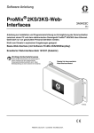
Advanced Web Interface Module Shown
TI12933b
Related Manuals
Contents
Related Manuals . . . . . . . . . . . . . . . . . . . . . . . . . . . 2
Warnings . . . . . . . . . . . . . . . . . . . . . . . . . . . . . . . . . 3
ProMix 2KS/3KS Basic Web Interface (BWI) . . . . . 4
Installation . . . . . . . . . . . . . . . . . . . . . . . . . . . . . . 4
Web Navigation Screens . . . . . . . . . . . . . . . . . . . 8
Install the Advanced Web Interface (AWI) Module 12
Overview . . . . . . . . . . . . . . . . . . . . . . . . . . . . . . 12
Location . . . . . . . . . . . . . . . . . . . . . . . . . . . . . . 12
Mounting . . . . . . . . . . . . . . . . . . . . . . . . . . . . . . 12
Connect Module to EasyKey and PC . . . . . . . . 13
Computer Configuration . . . . . . . . . . . . . . . . . . . . 16
Set up an Automatic IP Address . . . . . . . . . . . . 16
System Initialization . . . . . . . . . . . . . . . . . . . . . 16
Password Recovery . . . . . . . . . . . . . . . . . . . . . 18
Set the Network Configuration . . . . . . . . . . . . . . 19
AWI Screens . . . . . . . . . . . . . . . . . . . . . . . . . . . . . . 21
Network Tab . . . . . . . . . . . . . . . . . . . . . . . . . . . . 21
Materials Tab . . . . . . . . . . . . . . . . . . . . . . . . . . . 22
Settings Tab . . . . . . . . . . . . . . . . . . . . . . . . . . . . 24
System Setup Screens . . . . . . . . . . . . . . . . . . . 26
Replace AWI Board . . . . . . . . . . . . . . . . . . . . . . . . 36
Parts . . . . . . . . . . . . . . . . . . . . . . . . . . . . . . . . . . . . 38
15V337 Advanced Web Interface Module . . . . . 38
15V336 Advanced Web Interface Server Hub . . 39
Electrical Schematic . . . . . . . . . . . . . . . . . . . . . . . 40
Dimensions . . . . . . . . . . . . . . . . . . . . . . . . . . . . . . . 41
Graco Standard Warranty . . . . . . . . . . . . . . . . . . . 42
Graco Information . . . . . . . . . . . . . . . . . . . . . . . . . 42
Related Manuals
Component Manuals in English
2
Manual
Description
312775
312776
312777
312778
312779
312780
313881
313882
313883
313885
312781
312782
312783
312787
312784
310745
312786
312785
308778
310696
313212
313290
ProMix 2KS Manual System Installation
ProMix 2KS Manual System Operation
ProMix 2KS Manual System Repair-Parts
ProMix 2KS Automatic System Installation
ProMix 2KS Automatic System Operation
ProMix 2KS Automatic System Repair-Parts
ProMix 3KS Installation (All Systems)
ProMix 3KS Manual System Operation
ProMix 3KS Repair-Parts (All Systems)
ProMix 3KS Automatic System Operation
Fluid Mix Manifold
Dispense Valve
Color Change Valve Stacks
Color Change Module Kit
Gun Flush Box Kits
Gun Air Shutoff Kit
Dump Valve and Third Purge Valve Kits
Network Communication Kits
G3000/G3000HR/G250/G250HR Flow Meter
Coriolis Flow Meter
Gun Flush Box Integration Kit
Floor Stand Kit
313386D
Warnings
Warnings
The following warnings are for the setup, use, grounding, maintenance, and repair of this equipment. The exclamation point symbol alerts you to a general warning and the hazard symbol refers to procedure-specific risk. Refer back
to these warnings. Additional, product-specific warnings may be found throughout the body of this manual where
applicable.
WARNING
EQUIPMENT MISUSE HAZARD
Misuse can cause death or serious injury.
• Do not operate the unit when fatigued or under the influence of drugs or alcohol.
• Do not exceed the maximum working pressure or temperature rating of the lowest rated system
component. See Technical Data in all equipment manuals.
• Use fluids and solvents that are compatible with equipment wetted parts. See Technical Data in all
equipment manuals. Read fluid and solvent manufacturer’s warnings. For complete information
about your material, request MSDS forms from distributor or retailer.
• Check equipment daily. Repair or replace worn or damaged parts immediately with genuine manufacturer’s replacement parts only.
• Do not alter or modify equipment.
• Use equipment only for its intended purpose. Call your distributor for information.
• Route hoses and cables away from traffic areas, sharp edges, moving parts, and hot surfaces.
• Do not kink or over bend hoses or use hoses to pull equipment.
• Keep children and animals away from work area.
• Comply with all applicable safety regulations.
ELECTRIC SHOCK HAZARD
Improper grounding, setup, or usage of the system can cause electric shock.
• Turn off and disconnect power at main switch before disconnecting any cables and before servicing
equipment.
• Connect only to grounded power source.
• All electrical wiring must be done by a qualified electrician and comply with all local codes and
regulations.
313386D
3
ProMix 2KS/3KS Basic Web Interface (BWI)
ProMix 2KS/3KS Basic Web Interface (BWI)
NOTE: Screen views in this manual are shown using
Microsoft Windows XP.
NOTE: The ProMix 2KS/3KS Basic Web Interface (BWI)
is supplied with all EasyKeys. To run the program, Java
Version 6 Update 10 (or later) must be loaded on your
computer. This is a free download.
Installation
1. Before connecting your computer to the EasyKey,
verify that Java Version 6 Update 10 (or later) is
loaded on your computer. To verify, go to Java.com
using your Internet browser and click on “Do I Have
Java?” for further information.
2. After verifying that Java is loaded on the computer,
connect the computer directly to the EasyKey, using
the 15G869 CAT5 ethernet crossover cable supplied with the EasyKey. See FIG. 1.
EasyKey
15G869 CAT5 Ethernet Crossover Cable
Computer
TI13102a
EasyKey (Bottom View)
TI12638a
CAT5 Cable Connector
FIG. 1. ProMix 2KS/3KS Basic Web Interface Connection
4
313386D
ProMix 2KS/3KS Basic Web Interface (BWI)
3. Before running the BWI software you must manually
assign an IP address to your computer:
a. On your computer, click on the Start button
to open the menu, then click
on Control Panel
b.
See FIG. 2. Double click on Network Connections. Double click on Local Area Connection to
open the Local Area Connection Status window.
Click on Properties to open the Local Area Connection Properties window. See FIG. 3.
.
FIG. 2. Assign IP Address on Computer
313386D
5
ProMix 2KS/3KS Basic Web Interface (BWI)
c.
In the Local Area Connection Properties window, scroll to Internet Protocol (TCP/IP) and
double click, to open the Internet Protocol
f.
Type in the following Subnet mask:
255.255.255.0
(TCP/IP) Properties window. See FIG. 4.
FIG. 4: Internet Protocol (TCP/IP) Window
FIG. 3: Local Area Connection Properties Window
NOTE: To reconnect to the user network, change the
setting back to “Obtain an IP Address Automatically.”
d. See FIG. 4. Set to “Use the following IP
address:”
e. Type in the following IP address:
192.168.178.201
g. Click on OK to accept the changes and close
the Internet Protocol (TCP/IP) Properties window.
h. Click on OK to close the Local Area Connection
Properties window.
i.
6
Close the Local Area Connection Status window
and Network Connections window.
313386D
ProMix 2KS/3KS Basic Web Interface (BWI)
4. On the EasyKey, go to System Configuration
Screen 5 and write down the IP number assigned to
that EasyKey (1-99). See FIG. 5.
•
If “ProMix web interface requires Java to run”
appears, verify that Java Version 6 Update 10
(or later) is loaded on your computer. See page
4.
FIG. 5: System Configuration Screen 5
NOTE: Verify that the wireless connection is turned off
(disabled) before performing step 5.
5. Open Microsoft Internet Explorer (Start>All Programs>Internet Explorer).
6. In the address area type http://192.168.178.__ (fill in
the last digit with the EasyKey IP number recorded
in step 4).
7. Press Enter.
8. Select Run when security screen appears. See FIG.
6.
FIG. 7. Main BWI Screen
FIG. 6: BWI Security Screen
9. Main software screen appears. See FIG. 7.
•
If “Cannot Read Firmware” appears check for
loose hardware connections.
313386D
7
ProMix 2KS/3KS Basic Web Interface (BWI)
Web Navigation Screens
From the main BWI screen (see FIG. 7) the operator can
select Setup, Software/Resets, or Reports.
NOTE: Before running the BWI program, check the
EasyKey Status screen to ensure that the system is in
Standby.
Restore setup values - allows files to be uploaded and
restored to the ProMix 2KS/3KS.
Display setup values - indicates what values are
currently being used for the system. Allows the operator
to verify that the right values are being used. See FIG. 9.
Setup
Download setup values - saves the ProMix 2KS/3KS
configuration to the PC. This file can be opened and
edited using Microsoft Excel, or used to set up multiple
systems.
FIG. 9: Display Set Up
FIG. 8: Download Setup Values
8
313386D
ProMix 2KS/3KS Basic Web Interface (BWI)
Download custom language - saves the current
system language to the PC. See FIG. 10. This file is
opened and a custom language added to the B column
of the Excel file.
Software/Resets
NOTE: Custom languages are limited to Ascii and Ascii
extended characters and a maximum of 32 characters.
Save the Excel file as a tab delineated file for uploading
purposes.
NOTE: If using the Graco Gateway in your system, disconnect its cable from the EasyKey before updating the
ProMix 2KS/3KS software.
Install EasyKey software - installs firmware for the current device (approximately 6 minutes). See FIG. 12.
Restore custom language - allows the custom language file to be uploaded to the ProMix 2KS/3KS.
FIG. 12: Install EasyKey Software
FIG. 10: Download Custom Language
Reset settings - places system back to factory default
mode. The screen will prompt for confirmation. See FIG.
13.
End current job - ends a job and adds material to
usage report. The screen will prompt for confirmation.
See FIG. 11.
FIG. 13: Reset Settings
Reset password - clears password if lost or forgotten.
The screen will prompt for confirmation. See FIG. 13.
FIG. 11: End Current Job
FIG. 14: Reset Password
313386D
9
ProMix 2KS/3KS Basic Web Interface (BWI)
Reports
NOTE: Display material usage report - shows the
material sprayed from the ProMix 2KS/3KS. See FIG.
15.
Clear material usage report - deletes the material
usage from the display.
FIG. 16: Clear Material Usage Report
Download job log - downloads the job log to the PC.
FIG. 15: Display Material Usage Report
FIG. 17: Download Job Log
Download error log - downloads the error log to the
PC.
FIG. 18: Download Error Log
10
313386D
ProMix 2KS/3KS Basic Web Interface (BWI)
Display job log - displays the job number, date, time,
recipe, ratio, target, volumes, grand totals, and any
errors that occurred during the job. See FIG. 22.
Clear job log - deletes the jobs from the display. The
screen will prompt for confirmation. See FIG. 20.
Display error log - displays the number of alarms, date,
time, recipe and what the error was. See FIG. 19.
FIG. 20: Clear Job Log
Clear error log - deletes the errors from the display. The
screen will prompt for confirmation. See FIG. 21.
FIG. 19: Display Error Log
FIG. 21: Clear Error Log
NOTE: For ProMix 3KS, a column
will appear for Vol C.
Scroll to right to view Grand Totals and Errors
FIG. 22: Display Job Log
313386D
11
Install the Advanced Web Interface (AWI) Module
Install the Advanced Web Interface (AWI) Module
Overview
Mounting
The Graco Advanced Web Interface (AWI) Accessory
allows communication between multiple ProMix
2KS/3KS and a PC over an Ethernet, enabling users to
monitor the ProMix 2KS/3KS, view and change system
setup parameters, and create reports.
1. See Dimensions, page 41.
NOTE: Screen views in this manual are shown using
Microsoft Windows XP.
2. Ensure that the wall and mounting hardware are
strong enough to support the weight of the equipment, fluid, hoses, and stress caused during operation.
Location
3. Using the equipment as a template, mark the
mounting holes on the wall at a convenient height
for the operator and so equipment is easily accessible for maintenance.
The AWI module may be installed in a local ProMix network (see FIG. 25) or in a LAN network (see FIG. 26).
4. Drill mounting holes in the wall. Install anchors as
needed.
5. Bolt equipment securely.
Do not install equipment approved only for non-hazardous location in a hazardous area.
Install the module near the EasyKey, in a non-hazardous area.
12
313386D
Install the Advanced Web Interface (AWI) Module
Connect Module to EasyKey and
PC
NOTICE
To avoid damaging circuit board when servicing, wear
grounding strap on wrist and ground appropriately.
1. Shut off ProMix 2KS/3KS power (0 position). FIG.
23. Also shut off power at main circuit breaker.
2. Run a CAT5 cable from the EasyKey connector
through the grommet and connect it to any port in
the AWI module. Connect another CAT5 cable from
the AWI module to the PC. See FIG. 24.
3. Plug in the module power cord.
NOTE: Multiple AWI server hubs can be connected to
the AWI master module in series. See FIG. 25. Order
Part No. 15V336 Hub, see page 39.
0 = OFF
TI12657a
FIG. 23: Power Off
EasyKey (Bottom View)
Advanced Web Interface Module
Connect CAT5 Cables to any ports on module
TI12926a
TI12638a
CAT5 Cable Connector
CAT5 Cable Grommets
FIG. 24: EasyKey and Module Cable Connection Points
313386D
13
Install the Advanced Web Interface (AWI) Module
AWI Master Module
EasyKeys
Computer
AWI Hub
Use CAT5 cables for connections.
TI13065a
FIG. 25: ProMix Network Typical Installation
14
313386D
Install the Advanced Web Interface (AWI) Module
EasyKey
EasyKey
LAN Network
NOTE: LAN Network (Manual)
Installation requires completion of
the procedures on pages 16-20
before connecting to the network.
Computer
AWI Module
Use CAT5 cables for connections.
Internet
(via VPN)
Computer
TI13064b
FIG. 26: LAN Network (Manual) Typical Installation
313386D
15
Computer Configuration
Computer Configuration
Set up an Automatic IP Address
System Initialization
See FIG. 27. On your computer, go to Control
Panel>Network Connections>Local Area Connection>Properties>Internet Protocol (TCP/IP). Verify that
“Obtain an IP address automatically” is selected in the
TCP/IP Properties window. If not, set it as shown. Click
OK and close out of the Control Panel.
NOTE: System initialization must be done by an administrator. This process is only required when the system
is first started.
Set to automatic IP address
NOTE: Verify that the wireless connection is turned off
(disabled) before performing step 1.
1. Open a browser. Firefox 3.0 or above is preferred.
Microsoft Internet Explorer 6.0 or above is also
acceptable.
2. Applies to Firefox only: To operate in a ProMix
2KS/3KS network with Firefox, you must turn off the
Proxy setting on your browser. In your Firefox
browser, go to Tools>Options>Advanced>Network
tab>Connection Settings. Click “No proxy.” See FIG.
28.
FIG. 27. Set Automatic IP Address
FIG. 28. Turn Off Proxy Setting (Firefox only)
3. Type http://gracoawi: in the browser address bar,
and press Enter.
16
313386D
Computer Configuration
4. The Welcome screen will appear. See FIG. 29. Click
Next.
6. Initialization is complete. See FIG. 31. Click Finish.
FIG. 31. System Initialization Step 3
FIG. 29. System Initialization Step 1
5. The Security screen will appear. See FIG. 30. The
administrator must fill in all fields. Click Next.
7. The Login screen will appear. See FIG. 32. Type in
the login name and password you entered in step 5.
Click Sign in. The Network screen will appear. See
page 21.
FIG. 30. System Initialization Step 2
FIG. 32. Login Screen
313386D
17
Computer Configuration
Password Recovery
1. If you type in the wrong password, sign in will be
blocked. See FIG. 33. Click on the block icon
initiate the password recovery sequence.
to
Click on block icon
FIG. 33. Sign in Blocked
2. See FIG. 34. The system will prompt you for your
login name. Type in the name you entered in step 5
on page 17, then click Next.
FIG. 34. Password Recovery Step 1
18
3. The system will then ask the secret question you
entered in step 5. Type in the answer, then click
Next.
FIG. 35. Password Recovery Step 2
4. If the answer matches the one entered in step 5, the
system will prompt you for a new password. Enter
the new password twice, then click Next. The system will return to the Login screen, FIG. 32.
FIG. 36. Password Recovery Step 3
313386D
Computer Configuration
Set the Network Configuration
ProMix 2KS/3KS Network Configuration
In a ProMix 2KS/3KS network, the AWI module is connected to an EasyKey and a personal computer. Up to
100 EasyKeys may be connected in the network. See
FIG. 25.
To select a ProMix 2KS/3KS network, go to the Settings
tab and select ProMix network. See FIG. 37.
Click Save.
Turn off the Proxy setting (Firefox only). See page 16.
FIG. 37. ProMix 2KS/3KS Network Setting
313386D
19
Computer Configuration
LAN Network (Manual) Configuration
See FIG. 26. A LAN network (manual) configuration
enables you to work through a local network. Up to 100
EasyKeys may be connected in the network. The
EasyKeys and AWI Module must be on the same subnetwork. The EasyKeys can be connected to any LAN
drop.
NOTE: To change to a LAN (manual) configuration, you
must first connect to the AWI via the ProMix 2KS/3KS
network. See pages 16-17 for instructions and FIG. 25
for cable connections.
To select a LAN (manual) configuration, go to the Settings tab and select Manual configuration. You will be
required to enter IP, gateway, and Netmask addresses.
Contact your IS system administrator for assistance.
See FIG. 38.
NOTE: Use a new IP address to access the AWI; this
replaces gracoawi (for LAN network systems only).
NOTE: Once Save is clicked, the AWI will disconnect the
user computer. Reconnect the AWI and computer as
shown in FIG. 26. Reconfigure the user computer to
match the new LAN configuration. You can then login to
the AWI using the newly assigned IP address.
Click Save to apply the change.
FIG. 38. LAN Network Setting
20
313386D
AWI Screens
AWI Screens
This section describes how to use the AWI screens to
access and make changes to system settings and recipes. For complete information about these settings and
their effects, see the Setup section in the system operation manual.
Network Tab
Use the Network tab to select the desired EasyKey. See
FIG. 39.
Each EasyKey must have a unique name and IP
address. See the Configuration Screen in FIG. 46 to set
the Station name (1-99).
Click on the desired EasyKey to access the setup
screens for that device.
Click on desired EasyKey
FIG. 39. Network Tab
313386D
21
AWI Screens
Materials Tab
Use the Materials tab to enter information on Volatile
Components (VOC) and Hazardous Air Pollutants (HAP)
for each material being used in your system, for material
reporting. This information, and the manufacturer’s part
no., are available on the MSDS sheet provided by the
material manufacturer. See FIG. 40.
VOC values may be set at Lbs/Gal or Gram/Liter as
desired, using the pulldown menu.
To add a new material, click the Plus
the values in the new data fields.
To delete a material, click the Minus
To save your changes, click
button. Enter
button.
.A
checkmark (✓)will appear when the save is complete.
Minus
Button
Plus
Button
VOC Pulldown Menus
(Lb/Gal or Gram/Liter)
Save
Button
FIG. 40. Materials Tab
22
313386D
AWI Screens
313386D
23
AWI Screens
Settings Tab
Use the Settings tab to configure the main system settings (Time, Language, Upgrade AWI, and Edit
Accounts).
NOTE: FIG. 41 shows the Settings screen when you log
in as a user. FIG. 42 shows the Settings screen when
you log in as a system administrator.
Set Language
Set the desired language of the screen text, using the
pulldown menu. Select English (default), Spanish,
French, German, Italian, Dutch, Japanese (Kanji),
Korean, and Chinese (Simplified).
Upgrade AWI Software
Set Time
To synchronize the time settings on all networked ProMix 2KS/3KS devices, click the Sync
button.
The change will take place in approximately one minute.
To upgrade AWI, first download the latest version of AWI
software to your computer. Contact your Graco distributor for information.
Use the Browse
button to locate the file
on your computer. Highlight the filename.
Click on the Upgrade
upgrade.
Latest Software Version
Browse
button to start the
Sync Button
Upgrade
FIG. 41. System Settings Tab (User Screen Shown)
24
313386D
AWI Screens
Edit Account Information
•
NOTE: Account information can only be entered by a
system administrator. See FIG. 42.
•
butTo add a new account, click the Add User
ton. Enter the information in the data fields. Click
•
To edit an existing account, click the Edit User
button. Enter the information in the data fields. Click
. A checkmark (✓)will appear the top
right corner when the save is complete.
To delete an existing account, click the Delete User
button.
. A checkmark (✓)will appear in the top
right corner when the save is complete.
Latest Software Version
Browse
Sync Button
Upgrade
FIG. 42. System Settings Tab (Admin Screen Shown)
313386D
25
AWI Screens
System Setup Screens
To view the system setup screens, go to the Network tab
and click on the desired EasyKey to access the setup
screens for that device. See FIG. 43.
Monitor Tab
Select the Monitor tab to view data from the EasyKey
Status screen, in real time. See FIG. 44.
Click on desired EasyKey
FIG. 43. Open Device
FIG. 44. Monitor Tab
26
313386D
AWI Screens
Material Setup Tab
Go to the Material Setup tab to assign a catalyst, color,
reducer (on 3KS) and flush material for the valves of the
active device, using the pulldown menus. For 2KS, each
device may include up to 30 color valves, 4 catalyst
valves, and solvent flush valves. For 3KS, each device
may include up to 25 color valves, 4 catalyst valves, 4
reducer valves, and solvent flush valves. The materials
listed in each pulldown menu were established under
the Materials Tab on page 22. See FIG. 45.
To save your changes, click
.A
checkmark (✓)will appear when the save is complete.
FIG. 45. Material Setup Tab
313386D
27
AWI Screens
System Setup Tab
The Setup tab has three editable screens:
•
•
•
The Configuration screen corresponds to the System Configuration screens of the EasyKey. See FIG.
46. For complete information about these settings
and their effects, see the Setup section in the system operation manual.
The Advanced screen corresponds to the
Advanced Setup screens of the EasyKey. See FIG.
47. For complete information about these settings
and their effects, see the Setup section in the system operation manual.
The Recipe screen corresponds to the Recipe
Setup screens of the EasyKey. See FIG. 48. For
complete information about these settings and their
effects, see the Setup section in the system operation manual.
Use the arrow buttons
to view the pre-
vious or the next recipe, or enter the recipe number
and press Enter.
Click on the Chart button
to create a
timing chart of the active recipe. See FIG. 49.
To save your changes, click
.A
checkmark (✓)will appear when the save is complete.
NOTE: Changes made on the EasyKey screen before
clicking
will be overwritten by the
AWI data.
50 cc
FIG. 46. System Setup Tab, Configuration Screen
28
313386D
AWI Screens
FIG. 47. System Setup Tab, Advanced Screen
Click to create a
recipe timing chart.
See FIG. 49.
1.0
2.0
FIG. 48. System Setup Tab, Recipe Screen
313386D
29
AWI Screens
FIG. 49. Sample Recipe Timing Chart
30
313386D
AWI Screens
Reports Tab
The Reports tab enables you to produce three reports:
• Material Report
• Job Report
• Alarm Report
Select which of the three reports you want to create.
Click the desired output format
Click the Create button
to gener-
ate the report.
Material Report
See FIG. 50. The Material Report compiles VOC and
HAP data for all recipes and jobs using a material, and
the total amount of material used. The material must be
assigned to a valve to be included in the report (see
page 27).
for the report:
•
•
CSV (can be imported into Microsoft Excel).
TXT (straight text).
Click the Reset button
to begin a new report
cycle (usually monthly).
FIG. 50. Material Report Screen
313386D
31
AWI Screens
Job Report
See FIG. 51. The Job Report provides detailed information on all completed jobs within a designated time
period.
Set the time frame by using the Calendar buttons
the right of each date box.
to
NOTE: The dates use the day/month/year format.
Select the information desired by clicking on the box to
the left of each parameter.
FIG. 51. Job Report Screen
32
313386D
AWI Screens
Alarm Report
See FIG. 52. The Alarm Report lists all alarms triggered
within a designated time period.
Set the time frame by using the Calendar buttons
the right of each date box.
to
NOTE: The dates use the day/month/year format.
FIG. 52. Alarm Report Screen
313386D
33
AWI Screens
Level Control Tab
See FIG. 53. The Level Control Tab allows you to input
the supply tank volume of the materials and the level at
which an alarm should be triggered.
The alarm function may be turned on or off for each
material valve.
FIG. 53. Level Control Tab
34
313386D
AWI Screens
Sidebar
•
See FIG. 54. The Sidebar relates to the EasyKey being
monitored. It has four links to related screens:
•
•
Save - saves the current device configuration into a
file.
•
Restore - restores configurations of the device from
a file.
Copy (Sync Settings)- copies the configuration of
this device into other devices.
Install Firmware - install firmware for the current
device (approximately 5 minutes).
FIG. 54. Sidebar and Related Screens
313386D
35
Replace AWI Board
Replace AWI Board
•
To avoid electric shock, turn off EasyKey power
before servicing.
Shut off power at main circuit breaker.
All electrical wiring must be done by a qualified
electrician and comply with all local codes and regulations.
Read Warnings, page 3.
•
•
•
NOTICE
To avoid damaging circuit board when servicing, wear
Part No. 112190 grounding strap on wrist and ground
appropriately.
1. Shut off ProMix 2KS/3KS power (0 position).
2. Shut off power at main circuit breaker.
3. Open the AWI module.
4. Disconnect the cable (15) and wires (17, 18) from
the board (22). FIG. 55.
5. Remove the screws (21) and board (22).
6. Install the new board. Reconnect the cable (15) and
wires (17, 18).
10
4
18
15
17
22
TI12928a
FIG. 55. Replace AWI Board
36
313386D
Replace AWI Board
313386D
37
Parts
Parts
15V337 Advanced Web Interface Module
13
7, 9, 12
3
Screw Location
(item 28)
8
10
TI12926a
12
21
22
11
1, 2
To 4
4
5
17
18
To 10
5
6
17
15
10
Wiring Diagrams
+24
COM
V1+
V1-
+24
COM
+24
COM
4
18
17
18
22
To 4
17
To 22
18
TI12928a
TI12927a
Ref.
No.
Part No.
Description
1
2
3
4
5
6
7
8
9
10
11
15V339
15T752
n/a
120369
15V345
111987
n/a
186620
n/a
15V342
120838
PANEL, back
COVER
DIN RAIL
POWER SUPPLY, 24 Vdc
GROMMET, cable entry
CONNECTOR, strain relief
WIREWAY
LABEL, ground
COVER, wireway
SWITCH, ethernet
BLOCK, clamp end
38
Power Supply Wiring Detail
Qty
1
1
1
1
2
1
1
1
1
1
2
L1+
OUT - -
NC
DC - -
NC
24V + +
N-
1A + DC OK
Ref.
No.
Part No.
Description
12
13
15
17
18
21
22
28
103833
112443
121994
n/a
n/a
15V340
258355
n/a
SCREW, machine
BLOCK, terminal, ground
CABLE, CAT5
WIRE, copper, 16 ga.; 9 in. (230 mm)
WIRE, copper, 16 ga; 9 in. (230 mm)
STANDOFF, board
BOARD, server
SCREW, machine, serrated
hex-head
Qty
4
1
1
1
1
4
1
4
Parts labeled n/a are not available separately.
313386D
Parts
15V336 Advanced Web Interface Server Hub
13
7, 9, 12
3
Screw Location
(item 28)
8
10
12
11
1, 2
5
5
4
6
TI13204a
Wiring Diagrams
17
4
To 4
17
10
To 10
+24
V1+
COM
V1-
18
Ref.
No.
Part No. Description
1
2
3
4
5
6
7
8
9
15V339
15T752
n/a
120369
15V345
111987
n/a
186620
n/a
PANEL, back
COVER
DIN RAIL
POWER SUPPLY, 24 Vdc
GROMMET, cable entry
CONNECTOR, strain relief
WIREWAY
LABEL, ground
COVER, wireway
TI13205a
TI13206a
18
Qty
1
1
1
1
2
1
1
1
1
Ref.
No.
Part No. Description
10
11
12
13
17
15V342
120838
103833
112443
n/a
18
n/a
28
n/a
Qty
SWITCH, ethernet
BLOCK, clamp end
SCREW, machine
BLOCK, terminal, ground
WIRE, copper, 16 ga.; 9 in.
(230 mm)
WIRE, copper, 16 ga; 9 in.
(230 mm)
1
2
4
1
1
SCREW, machine, serrated
hex-head
4
1
Parts labeled n/a are not available separately.
313386D
39
Electrical Schematic
Electrical Schematic
Non-Hazardous Area
MEMBRANE
SWITCH
WITH
RIBBON
CABLE
J4
1
2
3
4
5
6
7
8
9
10
11
DISPLAY
BOARD
J9
J6
RJ45
1
2
3
4
RJ45
J2
DISPLAY
1
2
3
4
5
6
7
8
9
10
11
12
13
14
15
16
17
18
19
20
1
2
3
4
J5 5
6
7
8
9
10
J10
1
2
3
4
5
6
J7
J8
P1
RJ45
RJ45
3'
RJ45
BULKHEAD
RJ45
RJ45
3'
(25'-200' OPTIONS)
WEB SERVER
MODULE
100-240 Vac Input
24 Vdc
COM
40
313386D
Dimensions
Dimensions
16.57 in. (420.9 mm)
6.45 in.
(163.8 mm)
15.07 in. (382.8 mm)
8.71in.
(221.2 mm)
5.31in.
(134.9 mm)
TI12926a
313386D
TI12825b
41
Graco Standard Warranty
Graco warrants all equipment referenced in this document which is manufactured by Graco and bearing its name to be free from defects in
material and workmanship on the date of sale to the original purchaser for use. With the exception of any special, extended, or limited warranty
published by Graco, Graco will, for a period of twelve months from the date of sale, repair or replace any part of the equipment determined by
Graco to be defective. This warranty applies only when the equipment is installed, operated and maintained in accordance with Graco’s written
recommendations.
This warranty does not cover, and Graco shall not be liable for general wear and tear, or any malfunction, damage or wear caused by faulty
installation, misapplication, abrasion, corrosion, inadequate or improper maintenance, negligence, accident, tampering, or substitution of
non-Graco component parts. Nor shall Graco be liable for malfunction, damage or wear caused by the incompatibility of Graco equipment with
structures, accessories, equipment or materials not supplied by Graco, or the improper design, manufacture, installation, operation or
maintenance of structures, accessories, equipment or materials not supplied by Graco.
This warranty is conditioned upon the prepaid return of the equipment claimed to be defective to an authorized Graco distributor for verification of
the claimed defect. If the claimed defect is verified, Graco will repair or replace free of charge any defective parts. The equipment will be returned
to the original purchaser transportation prepaid. If inspection of the equipment does not disclose any defect in material or workmanship, repairs will
be made at a reasonable charge, which charges may include the costs of parts, labor, and transportation.
THIS WARRANTY IS EXCLUSIVE, AND IS IN LIEU OF ANY OTHER WARRANTIES, EXPRESS OR IMPLIED, INCLUDING BUT NOT LIMITED
TO WARRANTY OF MERCHANTABILITY OR WARRANTY OF FITNESS FOR A PARTICULAR PURPOSE.
Graco’s sole obligation and buyer’s sole remedy for any breach of warranty shall be as set forth above. The buyer agrees that no other remedy
(including, but not limited to, incidental or consequential damages for lost profits, lost sales, injury to person or property, or any other incidental or
consequential loss) shall be available. Any action for breach of warranty must be brought within two (2) years of the date of sale.
GRACO MAKES NO WARRANTY, AND DISCLAIMS ALL IMPLIED WARRANTIES OF MERCHANTABILITY AND FITNESS FOR A
PARTICULAR PURPOSE, IN CONNECTION WITH ACCESSORIES, EQUIPMENT, MATERIALS OR COMPONENTS SOLD BUT NOT
MANUFACTURED BY GRACO. These items sold, but not manufactured by Graco (such as electric motors, switches, hose, etc.), are subject to
the warranty, if any, of their manufacturer. Graco will provide purchaser with reasonable assistance in making any claim for breach of these
warranties.
In no event will Graco be liable for indirect, incidental, special or consequential damages resulting from Graco supplying equipment hereunder, or
the furnishing, performance, or use of any products or other goods sold hereto, whether due to a breach of contract, breach of warranty, the
negligence of Graco, or otherwise.
FOR GRACO CANADA CUSTOMERS
The Parties acknowledge that they have required that the present document, as well as all documents, notices and legal proceedings entered into,
given or instituted pursuant hereto or relating directly or indirectly hereto, be drawn up in English. Les parties reconnaissent avoir convenu que la
rédaction du présente document sera en Anglais, ainsi que tous documents, avis et procédures judiciaires exécutés, donnés ou intentés, à la suite
de ou en rapport, directement ou indirectement, avec les procédures concernées.
Graco Information
For the latest information about Graco products, visit www.graco.com.
TO PLACE AN ORDER, contact your Graco distributor or call to identify the nearest distributor.
Phone: 612-623-6921 or Toll Free: 1-800-328-0211 Fax: 612-378-3505
All written and visual data contained in this document reflects the latest product information available at the time of publication.
Graco reserves the right to make changes at any time without notice.
Original instructions. This manual contains English. MM 313386
Graco Headquarters: Minneapolis
International Offices: Belgium, China, Japan, Korea
GRACO INC. AND SUBSIDIARIES • P.O. BOX 1441 • MINNEAPOLIS, MN 55440-1441 • USA
Copyright 2008, Graco Inc. All Graco manufacturing locations are registered to ISO 9001.
www.graco.com
Revised 09/2011