1
Instructions
LDM5 (Standard) & LDP5 (Preset)
Electronic Metered Dispense Valves
312668W
EN
For metered dispense of oils and antifreeze. For professional use only.
Not approved for use in European explosive atmosphere locations.
Models: See page 2
1000 psi (7 MPa, 69 bar) Maximum Working Pressure
5 gpm (19 lpm) Maximum Flow Rate
Important Safety Instructions
Read all warnings and instructions in this manual.
Save these instructions.
1
NOTICE
This dispense valve:
• must be calibrated upon installation (see pages 12
and 19). Dispense amounts will vary with fluid pressure, temperature, and type of fluid being dispensed.
• is designed to dispense petroleum-based lubricants and antifreeze only. Do not dispense windshield washer solvent with this dispense valve.
• is designed for indoor use only.
• is not designed for in-line installation.
• is designed for use with industrial grade batteries,
(see page 31).
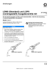
LDP5
Model 256216 shown
LDM5
Model 256215 shown
ti12063a
ti12065a
Models
Models
2
Extension
Meter
Model No.
LDM5
255751
LDM5
256215
LDM5
258693
X
LDM5
24F881
X
LDM5
24F882
LDM5
24F885
X
LDM5
24F887
X
LDM5
24F888
LDM5
24F891
X
LDP5
255277
X
LDP5
256216
LDP5
258694
X
LDP5
24F883
X
LDP5
24F884
LDP5
24F886
X
LDP5
24F889
X
LDP5
24F890
LDP5
24F892
LDP5
24X465
Rigid
Flex
Impact
Guard
Swivel
Cover
X
X
X
X
X
X
X
X
Inlet
NPT
BSPT
BSPP
X
X
X
X
X
X
X
X
X
X
X
X
X
X
X
X
X
X
X
X
X
X
X
X
X
X
X
X
X
X
X
X
X
X
X
X
X
X
X
X
X
X
X
X
X
312668W
Warnings
Warnings
The following warnings are for the setup, use, grounding, maintenance, and repair of this equipment. The exclamation point symbol alerts you to a general warning and the hazard symbol refers to procedure-specific risk. Refer back
to these warnings. Additional, product-specific warnings may be found throughout the body of this manual where
applicable.
WARNING
SKIN INJECTION HAZARD
High-pressure fluid from dispense valve, hose leaks, or ruptured components will pierce skin. This may
look like just a cut, but it is a serious injury that can result in amputation. Get immediate surgical
treatment.
• Do not point dispense valve at anyone or at any part of the body.
• Do not put your hand over the end of the dispense nozzle.
• Do not stop or deflect leaks with your hand, body, glove, or rag.
• Follow Pressure Relief Procedure in this manual, when you stop spraying and before cleaning,
checking, or servicing equipment.
EQUIPMENT MISUSE HAZARD
Misuse can cause death or serious injury.
• Do not operate the unit when fatigued or under the influence of drugs or alcohol.
• Do not exceed the maximum working pressure or temperature rating of the lowest rated system
component. See Technical Data in all equipment manuals.
• Use fluids and solvents that are compatible with equipment wetted parts. See Technical Data in all
equipment manuals. Read fluid and solvent manufacturer’s warnings. For complete information
about your material, request MSDS forms from distributor or retailer.
• Check equipment daily. Repair or replace worn or damaged parts immediately with genuine manufacturer’s replacement parts only.
• Do not alter or modify equipment.
• Use equipment only for its intended purpose. Call your distributor for information.
• Route hoses and cables away from traffic areas, sharp edges, moving parts, and hot surfaces.
• Do not kink or over bend hoses or use hoses to pull equipment.
• Keep children and animals away from work area.
• Comply with all applicable safety regulations.
FIRE AND EXPLOSION HAZARD
When flammable fluids are present in the work area, such as gasoline and windshield wiper fluid, be
aware that flammable fumes can ignite or explode. To help prevent fire and explosion:
• Use equipment only in well ventilated area.
• Eliminate all ignition sources, such as cigarettes and portable electric lamps.
• Keep work area free of debris, including rags and spilled or open containers of solvent and gasoline.
• Do not plug or unplug power cords or turn lights on or off when flammable fumes are present.
• Ground all equipment in the work area.
• Use only grounded hoses.
• If there is static sparking or you feel a shock, stop operation immediately. Do not use equipment
until you identify and correct the problem.
• Keep a working fire extinguisher in the work area.
312668W
3
Warnings
WARNING
PERSONAL PROTECTIVE EQUIPMENT
Wear appropriate protective equipment when in the work area to help prevent serious injury, including
eye injury, hearing loss, inhalation of toxic fumes, and burns. Protective equipment includes but is not
limited to:
• Protective eyewear, and hearing protection.
• Respirators, protective clothing, and gloves as recommended by the fluid and solvent manufacturer.
CALIFORNIA PROPOSITION 65
This product contains a chemical known to the State of California to cause cancer, birth defects or other
reproductive harm. Wash hands after handling.
4
312668W
Installation
Installation
Typical Installations
NOTICE
FIG. 1 shows a typical hose reel installation. Dispense
valves can also be installed on a console as shown in
Fig. 2.
The typical installation shown in Fig. 1 is only a guide. It
is not a complete system design. Contact your Graco
distributor for assistance in designing a system to suit
your needs.
KEY DESCRIPTION
A
Metered dispense valve
B
Fluid shut–off valve
C
Hose
D
Hose reel fluid inlet hose
E
Hose reel
A Thermal Relief Kit (not shown) is required. The kit
will vary by pump selected. See Parts, page 28 for a
list of available kits.
•
Do not use this dispense valve on non-Graco consoles. The trigger could be inadvertently pressed
while the dispense valve is stowed.
•
This dispense valve is not designed for in-line
installation. Do not install with a shut-off valve on
the outlet side of the meter which could damage
the meter housing cover.
Mounting Bracket
Mounting bracket 196471 is available for resting dispense valve on a console. See Fig. 2.
NOTICE
Do not obstruct the dispense valve trigger and do not
set the unit down resting on its trigger or it might not
stop dispensing.
D
B
E
mounting
bracket
196471
C
A
ti12081a
ti0274
FIG. 1
FIG. 2
312668W
5
Installation
Pressure Relief Procedure
Pre–Installation Procedure
1. Install the battery. See Replacing the Battery on
page 31.
2. Follow the Pressure Relief Procedure.
The equipment stays pressurized until pressure is manually relieved. To reduce the risk of serious injury from
pressurized fluid, accidental spray from the dispense
valve, or splashing fluid, follow this Pressure Relief
Procedure when you:
•
•
•
3. Close the shut–off valve (B, FIG. 1, page 5).
4. Ground the hose and reel or console. See
Grounding.
Leave a minimum of two engaged threads bare
when using PTFE tape. The bare threads ensure a
ground is maintained.
are instructed to relieve pressure.
check, clean, or service any system equipment.
install or clean fluid nozzles or filter.
1. Turn off the power supply to the pump.
2. Trigger the dispense valve into a waste container to
relieve pressure.
3. Open any bleed–type master air valves and fluid
drain valves in the system.
4. Leave the drain valve open until you are ready to
pressurize the system.
Grounding
Installation Procedure
NOTICE
If this is a new installation or if there is contaminated
fluid in the lines, flush the lines before you install the
metered valve. Contaminated lines could cause the
valve to leak.
If this is an existing installation, go to step 7. Steps 1 - 6
are the Flushing Procedure.
Proper grounding is an essential part of maintaining a
safe system. The movement of fluids through the dispensing system generates static electricity. Static electricity can cause fumes to ignite, resulting in explosion
and fire. To reduce the risk of static sparking, ground all
system components per local and national electrical
codes. Refer to user manuals for pump and other system components to ground the following:
•
Pump: Follow manufacturer’s recommendations.
•
Air and Fluid hoses: Use only grounded
hoses.
•
Air compressor: Follow the manufacturer’s
recommendations.
•
Fluid supply container: Follow the local code.
To maintain grounding continuity when flushing or
relieving pressure, always hold a metal part of valve
firmly to side of grounded metal pail, then trigger valve.
B
ti12081a
FIG. 3
1. Close the fluid shutoff valve (B, FIG. 3) at each dispense position.
2. Make sure:
•
•
•
the main fluid outlet valve at the pump is closed,
the air pressure to the pump motor is adjusted,
the air valve is open.
3. Slowly open main fluid valve.
6
312668W
Installation
4.
a. Place the hose end (with no dispense valve
connected) into a container for waste oil.
b. Secure the hose in the container so it will not
come out during flushing.
c.
If you have multiple dispense positions, first
flush the dispense position farthest from the
pump, then work your way toward the pump.
Electronic Control Control (1) and Gasket
(2) Installation
Kits: 257350 and 257351
NOTICE
It is important to properly seat gasket (2) when installing electronic control (1) to fluid section. An improperly seated gasket could cause the meter to report
invalid dispense amounts because the glass reed
switches are broken.
1
2
B
FIG. 5
ti12081a
FIG. 4
Connecting Hose to Meter
5. Slowly open the shut–off valve (B, FIG. 4) at the dispense position. Flush out a sufficient amount of oil
to ensure that the entire system is clean. Close the
valve.
34
4
6. Repeat step 5 at all other dispense positions.
hose
fitting
ti0269
FIG. 6
1. Follow the Pressure Relief Procedure, page 6.
2. Slide the swivel cover (34) onto the hose, small end
first, before connecting hose fitting to swivel (4)
(FIG. 6).
3. Apply thread sealant to the male threads of the hose
fitting. Thread the hose fitting into the swivel (4) and
tighten firmly (FIG. 6).
Make sure you let sealant cure to the manufacturer’s recommendations before you let fluid into
the system.
312668W
7
Installation
Installing Extension and Nozzle on Meter
B
26a
26c
26b
ti12081a
FIG. 8
FIG. 7
1. Thread the sealing nut (26c) onto the extension
(26a).
2. Thread extension into meter outlet at least three full
turns to tighten securely. (FIG. 7). (Over torquing
may cause casting meter to split)
NOTICE
•
Do not overtighten extension to sealing nut. Over
tightening may cause meter casting to split.
•
Do not use a twist/lock or manual shut-off nozzle.
You must use an automatic nozzle on the meter or
the meter could be damaged.
4. Open all dispense position shut-off valves (B, FIG.
8) and start the pump to pressurize the system. See
Operation, (LDM5 Meters - page 13; LDP5 Meters page 22), for proper operation of meter.
•
To ensure dispensing accuracy, purge all air
from the fluid lines and dispense valve before
you use it.
•
Set the system flow to the desired flow rate,
which is typically 1.5 gpm. Do not exceed a
5-gpm flow rate.
3. Thread new nozzle (26b) onto extension. With an
open-end, adjustable wrench.Tighten it firmly.
Only tighten nozzle with the wrench on the flats of
the nozzle bushing. Do not disassemble the
bushing from the nozzle. Disassembly will affect
the performance of the nozzle.
8
312668W
LDM5 Meter Setup and Operation Instructions
LDM5 Meter Setup and Operation Instructions
Setup
Terms
Keypad Buttons (FIG. 9)
The following terms are shown on the display and/or
used often in this instruction manual.
•
R-TOTAL: Resettable Total
Shows the cumulative amount that has been dispensed. Can be reset to zero.
•
TOTAL: Non–Resettable Total
Shows the cumulative amount that has been dispensed for the life of the unit. Cannot be reset.
•
Standard Dispense Mode
Dispense mode in which display counts up from
zero or from where it recently stopped.
•
ASLEEP / AWAKE Mode
Asleep is a battery–saving mode in which the display goes blank after 45 seconds of inactivity. The
display comes Awake from sleep mode when you
press any button on the keypad or squeeze the trigger to dispense fluid.
AUTO
PTS QTS
GAL
LITERS
R-TOTAL
Min. Dispense Volume 0.5 liter
(0.13 gal)
Minimum Flow Rate
1.0 l/min.
(0.26 gpm)
Maximum Flow Rate
19.0 l/min. (5.00 gpm)
Maximum Working Pressure: 70 bar (1000 PSI)
ti12043A
FIG. 9
•
TOTAL*
Displays the resettable total, non–resettable total,
and calibration factor.
•
RESET*
Resets the displayed amount to zero or press to
enter the Standard Dispense Mode (see Terms).
* Press the hold Reset and Total
buttons simultaneously to display Setup Menus (page 10).
All buttons are disabled while fluid is being
dispensed.
312668W
9
LDM5 Meter Setup and Operation Instructions
Setup Menus (FIG. 10)
c.
AUTO
PTS QTS
GAL
LITERS
R-TOTAL
Min. Dispense Volume 0.5 liter
(0.13 gal)
Minimum Flow Rate
1.0 l/min.
(0.26 gpm)
Maximum Flow Rate
19.0 l/min. (5.00 gpm)
Maximum Working Pressure: 70 bar (1000 PSI)
FIG. 10
Press and hold Reset button again to display
Calibration Menu. When this menu is displayed
CAL blinks on the screen (FIG. 13).
The total that is displayed when you leave each
menu is the total that is stored.
The following sections of this manual provide
instructions for using the Setup Menus.
ti12044a
1. If the display is blank (asleep), wake it up by pressing any button on the keypad (FIG. 10).
2. Press and hold the Total and
Reset buttons simultaneously
for approximately six (6) seconds to enter the Setup
Menus (FIG. 10).
During the first 4 seconds all segments display.
Then for 2 seconds the software version number
displays.
3.
There are three (3) Setup Menus available, stored in
a preset order.
a. The first screen displayed is the Resettable
Total Menu. When this menu is displayed,
R-TOTAL will blink on the screen (FIG. 11).
b. Press and hold Reset button to display Units of
Measure Menu. When
this menu is displayed the
last set Unit of Measurement blinks on the screen
(FIG. 12).
10
312668W
LDM5 Meter Setup and Operation Instructions
Resettable Total (FIG. 11)
Units of Measurement (FIG. 12)
Resets dispensed total on screen to zero or stores displayed dispense total. The resettable total accumulates
until the next time it is manually reset.
Sets unit of measurement to quarts, gallons, pints, or
liters.
Auto
PTS QTS
GAL
LITERS
R-TOTAL
AUTO
PTS QTS
GAL
LITERS
R-TOTAL
Min. Dispense Volume 0.5 liter
(0.13 gal)
Minimum Flow Rate
1.0 l/min.
(0.26 gpm)
Maximum Flow Rate
19.0 l/min. (5.00 gpm)
Maximum Working Pressure: 70 bar (1000 PSI)
Min. Dispense Volume 0.5 liter
(0.13 gal)
Minimum Flow Rate
1.0 l/min.
(0.26 gpm)
Maximum Flow Rate
19.0 l/min. (5.00 gpm)
Maximum Working Pressure: 70 bar (1000 PSI)
ti12045a
ti12047a
FIG. 11
1. If Resettable Total Menu is not already displayed,
complete steps 1 and 2 of Setup Menus section.
2. R-TOTAL blinks indicating you are on the Resettable Total Menu. The currently stored total and unit of
measurement is displayed (FIG. 11).
3. Do ONE of the following.
ti0272C
FIG. 12
1. If the Units of Measurement Menu is not already displayed, complete steps 1 - 3 of the Setup Menus
section, page 10.
2. The currently stored unit of measurement: GAL,
QTS, PTS or LITERS blinks indicating you are on
the Units of Measurement Menu screen.
3. To change the unit of measurement, do ONE of the
following.
a. Press and hold the Total
button. Resettable total is
set to zero (0).
0 GAL/QTS/PTS or 0
LITERS is displayed.
a. Press and hold Total button to display next unit of
measurement in the
sequence.
b. Press and hold the Reset
button. The zero (0) total
is stored. Units of Measurement Menu displays.
b. When measurement unit
you want to use is displayed, press and hold
Reset button. Display
advances to Calibration
Menu.
OR
•
Press and hold the Reset
button. The currently displayed total is stored. The
Units of Measurement
Menu displays.
312668W
OR
•
Press and hold Reset button. The currently displayed measurement unit
is stored. The Calibration
Menu displays.
11
LDM5 Meter Setup and Operation Instructions
Calibration (FIG. 13)
Recalibrates the meter for dispensing different fluids.
CAL
b. Press and hold Total
button until CAL stops
blinking and the display shows 1.00.
c. When CAL starts to
blink again, the display
should show 1.00. The
new calibration is complete.
PTS QTS
GAL
LITERS
R-TOTAL
If an error was made during meter recalibration,
repeat Steps a - c of the recalibration process to
recalibrate the meter again.
Min. Dispense Volume 0.5 liter
(0.13 gal)
Minimum Flow Rate
1.0 l/min.
(0.26 gpm)
Maximum Flow Rate
19.0 l/min. (5.00 gpm)
Maximum Working Pressure: 70 bar (1000 PSI)
ti12046a
3. Press and hold the Reset button. The unit returns to Standard Dispense Mode.
FIG. 13
1. If the Calibration Menu is not already displayed,
complete steps 1 - 4 of the Setup Menus section,
page 10.
2. CAL blinks indicating you are on the Calibration
Menu screen. Do ONE of the following.
Use the current calibration.
•
Press and hold Reset button to lock in amount. Display returns to the
Standard Mode.
OR
Recalibrate meter as follows:
a. If the unit of measurement is gallons, pints,
or quarts, dispense exactly one quart of fluid
into a calibrated 1–quart container.
If the unit of measurement is liters, dispense
exactly one liter of fluid into a calibrated
1–liter container.
For proper calibration, you must dispense the exact amount.
12
312668W
LDM5 Meter Setup and Operation Instructions
Operation
Dispensing Fluid in Standard Mode
All buttons are disabled while fluid is being dispensed.
AUTO
3. Squeeze the trigger.
Fluid begins to flow, and the amount shown on the
display counts up from zero.
PTS QTS
GAL
LITERS
R-TOTAL
AUTO
Min. Dispense Volume 0.5 liter
(0.13 gal)
Minimum Flow Rate
1.0 l/min.
(0.26 gpm)
Maximum Flow Rate
19.0 l/min. (5.00 gpm)
Maximum Working Pressure: 70 bar (1000 PSI)
PTS QTS
GAL
LITERS
R-TOTAL
Min. Dispense Volume 0.5 liter
(0.13 gal)
Minimum Flow Rate
1.0 l/min.
(0.26 gpm)
Maximum Flow Rate
19.0 l/min. (5.00 gpm)
Maximum Working Pressure: 70 bar (1000 PSI)
ti12043a
FIG. 14
ti12043a
FIG. 16
1. If the display was blank (in
sleep mode), press and hold
the Total or Reset button. The
amount of the last dispense
appears on the display (FIG.
14).
AUTO
4. Release the trigger when you have dispensed the
desired amount of fluid.
Fluid flow stops, and the amount you have dispensed is shown on the display (FIG. 16).
PTS QTS
GAL
LITERS
R-TOTAL
When you release the trigger, the nozzle should
prevent fluid from running out of the extension. If
fluid does run out, see Replacing the Nozzle on
page 31.
Min. Dispense Volume 0.5 liter
(0.13 gal)
Minimum Flow Rate
1.0 l/min.
(0.26 gpm)
Maximum Flow Rate
19.0 l/min. (5.00 gpm)
Maximum Working Pressure: 70 bar (1000 PSI)
ti12048a
FIG. 15
2. Press and hold Reset button.
0.00 is shown on the display
as shown in FIG. 15.
312668W
13
LDM5 Meter Setup and Operation Instructions
Viewing Totals
This is the procedure for viewing the non–resettable and
resettable totals in gallons or liters. To change the resettable total, see Resettable Total, page 11.
AUTO
1. If display is blank (in sleep
mode), press and hold either
the Total or Rest button.
AUTO
PTS QTS
GAL
LITERS
R-TOTAL
Min. Dispense Volume 0.5 liter
(0.13 gal)
Minimum Flow Rate
1.0 l/min.
(0.26 gpm)
Maximum Flow Rate
19.0 l/min. (5.00 gpm)
Maximum Working Pressure: 70 bar (1000 PSI)
PTS QTS
GAL
LITERS
R-TOTAL
Min. Dispense Volume 0.5 liter
(0.13 gal)
Minimum Flow Rate
1.0 l/min.
(0.26 gpm)
Maximum Flow Rate
19.0 l/min. (5.00 gpm)
Maximum Working Pressure: 70 bar (1000 PSI)
ti12049a
FIG. 17
2. Press and hold Total button.
The resettable total amount is
displayed (FIG. 17).
ti12050a
FIG. 18
3. Press and hold the Total button again to display the
non-resettable total (FIG. 18).
Each time you press and hold the Total button the
display toggles between the non–resettable and
resettable totals.
4. Press and hold the Reset button. The unit returns to Standard Dispense Mode.
If the unit of measurement is gallons, quarts, or
pints, the resettable total is displayed in gallons,
(FIG. 17). If the unit of measurement is liters, the
resettable total is displayed in liters.
14
312668W
LDM5 Meter Setup and Operation Instructions
Error Code
If an error code is shown on the
display, as shown in FIG. 19, you
can press the Reset button to
clear the error code and view the
dispensed amount. Even in an
error condition, the unit keeps
track of the amount dispensed.
AUTO
PTS QTS
GAL
LITERS
R-TOTAL
Min. Dispense Volume 0.5 liter
(0.13 gal)
Minimum Flow Rate
1.0 l/min.
(0.26 gpm)
Maximum Flow Rate
19.0 l/min. (5.00 gpm)
Maximum Working Pressure: 70 bar (1000 PSI)
ti12051a
FIG. 19
Error Code
Cause
Flow rate is higher than 5 gpm.
Adjust the flow rate so it is not higher
than 5 gpm.
Air was pumped through the line.
Purge air from the line.
Err 1
312668W
Solution
15
LDP5 Meter Setup and Operation Instructions
LDP5 Meter Setup and Operation Instructions
Setup
Locking and Unlocking the Trigger
Terms
The following terms are shown on the display and/or
used often in this instruction manual.
ti11349a
Locked Position
•
R-TOTAL: Resettable Total
Shows the cumulative amount that has been dispensed in all modes. Can be reset to zero.
•
TOTAL: Non–resettable Total
Shows the cumulative amount that has been dispensed in all modes for the life of the unit. Cannot
be reset.
•
Manual Mode
Dispense mode in which display counts up from
zero to show the dispensed amount. In this mode,
you may lock the trigger, but you must manually
unlock it when the desired amount is dispensed.
Memory setting also unlocks the trigger.
•
Auto Mode
Dispense mode in which a preset, user–entered
amount is dispensed. When the preset amount is
dispensed, the trigger unlocks to stop the unit from
dispensing and the amount dispensed is displayed.
At this point, you may dispense more by pulling
back the trigger, and the display resumes counting
up.
•
Asleep / Awake Mode
Asleep is a battery–saving mode in which the display goes blank after 45 seconds of inactivity. The
display comes Awake from sleep mode when you
press any button or squeeze the trigger to dispense
fluid.
FIG. 20
To lock the trigger (FIG. 20), press on the part of the
trigger that has the textured grip until you feel it click into
the locked position.
Unlocked Position
ti11348a
FIG. 21
To unlock the trigger (FIG. 21), press on the smooth
part of the trigger until you feel it click out of the locked
position. When you release the trigger, fluid flow stops.
In Auto mode, the unit stops dispensing when the
entered amount has been dispensed.
In Manual mode, the trigger does not automatically
unlock; you must unlock it manually.
16
312668W
LDP5 Meter Setup and Operation Instructions
Setup Menus (FIG. 23)
Keypad Buttons (FIG. 22)
AUTO
PTS QTS
GAL
LITERS
R-TOTAL
AUTO
PTS QTS
GAL
LITERS
R-TOTAL
ti12052a
FIG. 22
•
Manual / Reset*
Used to select Manual Mode dispensing (see
Terms). The first push selects the mode, and the
second push resets the display to zero.
•
Auto / Reset*
Used to select Auto Mode dispensing (see Terms).
The first push selects the mode, and the second
push resets the display to zero.
* Press Manual / Reset and
Auto / Reset buttons simultaneously to display the
Setup Menus (page 17).
•
Total
Used in any mode to see the
resettable total and the non–resettable total.
•
10, 1.0, and 0.1
Used in Auto Mode and during setup to enter dispense amounts.
All buttons are disabled while fluid is being dispensed.
ti12053a
FIG. 23
1. If the display is blank (asleep),
wake it up by pressing any
button on the keypad.
2. Press and hold the Manual/Reset and Auto/Reset
buttons simultaneously for
approximately 6 seconds to
enter the Setup Menus .
During the first 4 seconds all segments display.
Then for 2 seconds the software version number
displays.
3. There are five (5) Setup Menu screens available,
stored in a preset order.
a. The first screen displayed is the Resettable
Total Menu (FIG. 24, page 18). When the menu
is displayed, R-TOTAL (G) will blink in the lower
right corner on the screen.
b. Press and hold the Auto /
Reset button to display
the Units of Measure
Menu (FIG. 25, page 19).
When this menu is displayed the last set Unit of
Measurement blinks in
the lower right corner on the screen.
312668W
17
LDP5 Meter Setup and Operation Instructions
c.
Press and hold the Auto / Reset button again to
display the Calibration Menu (FIG. 26, page 19).
When this menu is displayed CAL will blink on
the screen.
Resettable Total (FIG. 24)
Resets the dispense total to zero or stores the displayed
dispense total. The resettable total accumulates until
the next time it is manually reset.
d. Press the Auto / Reset button again to display
the Auto Preset Amount Menu (FIG. 27, page
20). When this menu is displayed, AUTO blinks
and the currently stored auto preset amount is
displayed.
AUTO
PTS QTS
GAL
LITERS
R-TOTAL
e. Press the Auto / Reset button again to display
the Shut-off Default Amount Menu (FIG. 28,
page 21). When the menu is displayed the
clock icon blinks and the stored shut–off
default amount is displayed.
ti12054a
FIG. 24
The value that is displayed when you leave each menu
is the value that is stored.
1. If the Resettable Total screen is not already displayed, complete steps 1 - 2 of the Setup Menus
section.
2. R-TOTAL blinks indicating you are on the Resettable Total Menu screen. The currently stored total
and unit of measurement are displayed.
3. Do ONE of the following.
a. Press and hold the Manual / Reset button to reset
the total to zero (0).
b. Press and hold the Auto /
Reset button to store the
zero (0) measurement
unit. The Units of Measurement Menu displays.
OR
•
18
Press and hold the Auto /
Reset button to store the
currently displayed total.
The Units of Measurement Menu displays.
312668W
LDP5 Meter Setup and Operation Instructions
Units of Measurement (FIG. 25)
Calibration (FIG. 26)
Sets the units of measurement to gallons, quarts, pints,
or liters.
Recalibrates the meter for dispensing different fluids.
AUTO
PTS QTS
GAL
LITERS
R-TOTAL
CAL
PTS QTS
GAL
LITERS
R-TOTAL
ti12055a
ti12056a
FIG. 25
FIG. 26
1. If the Units of Measurement Menu is not already displayed, do steps 1- 3 in Setup Menus section, page
17.
1. If the Calibration Screen is not already displayed,
complete steps 1 - 4 of the Setup Menus section,
page 17.
2. GAL, QTS, PTS or LITERS blinks indicating you
are on the Units of Measurement Menu screen.
3. Do ONE of the following.
2. CAL blinks indicating you are on the Calibration
Menu screen.
3. Do ONE of the following.
a. Press and hold Manual /
Reset button to display
next unit of measurement
in sequence. Each time
you press and hold the
button, the next unit of
measurement displays.
b. When measurement unit
you want to use is displayed, press and hold
Auto / Reset button to
lock in new measurement
unit. Calibration Menu displays.
OR
•
Press and hold the Auto /
Reset button.
The currently displayed
measurement unit is
stored. Calibration Menu
displays.
312668W
Use the current calibration.
•
Press and hold the Auto /
Reset button to lock in the
displayed amount. The
display advances to the
Auto Preset Amount
Menu.
OR
Recalibrate the meter as follows.
a. If the unit of measurement is gallons, pints, or
quarts, dispense exactly one quart of fluid
into a calibrated 1–quart container.
If the unit of measurement is liters, dispense
exactly one liter of fluid into a calibrated
1–liter container.
For proper calibration, you must dispense
the exact amount.
19
LDP5 Meter Setup and Operation Instructions
3. Do ONE of the following.
b. Press and hold the
Manual / Reset button
until CAL stops blinking.
a. To enter a new auto preset amount press and
hold the 10 button to
change the 10’s digit,
c. When CAL starts to
blink again, the display
should show 1.00,
which indicates the new calibration is complete.
the 1.0 button to change
the 1’s digit,
If an error was made during meter recalibration,
repeat Steps a - c of the recalibration process to
recalibrate the meter again.
and the 0.1 button to
change the first decimal
digit. You cannot enter
zero.
d. Press and hold the
Auto / Reset button to
advance to the Auto
Preset Amount Menu.
Auto Preset Amount (FIG. 27)
To reset the display to 0.00, press and hold the
Manual / Reset button.
Specifies an amount displayed when you enter the Auto
Dispense Mode. Typically, you would enter the amount
you most frequently dispense.
AUTO
b. Press and hold the Auto /
Reset button to lock in the
amount. The Shut-Off
Default Amount Menu displays.
PTS QTS
GAL
LITERS
R-TOTAL
OR
•
ti12082a
FIG. 27
Press and hold the Auto /
Reset button to lock in the
currently displayed auto
preset amount. The display advances to the
Shut–Off Default Amount
Menu.
1. If the Auto Preset Amount screen is not already displayed, complete steps 1 - 5 of the Setup Menus
section, page 17.
2. AUTO blinks indicating you are in the Auto Preset
Amount Menu. The currently stored auto preset
amount is displayed. (This is the amount that is displayed when the Auto / Reset button is pressed
during normal operation.)
20
312668W
LDP5 Meter Setup and Operation Instructions
Shut–Off Default Amount (FIG. 28)
3. Do ONE of the following.
Prevents accidental overfills when dispensing with the
trigger locked in Manual mode. The shut–off default
amount is factory preset at 5 quarts.
AUTO
a. To enter a new shut–off
default amount, press and
hold the 10 button to
change the 10’s digit,
PTS QTS
GAL
LITERS
R-TOTAL
the 1.0 button to change
the 1’s digit,
and the 0.1 button to
change the first decimal
digit. You cannot enter
zero.
ti12058a
FIG. 28
1. If the Shut-Off Default Amount Menu is not already
displayed, complete steps 1 - 6 of the Setup Menus
section, page 17.
To reset the display to 0.00, press and hold the
Manual/Reset button.
2. The clock icon blinks indicating you are in the
Shut–off Default Amount Menu. The stored shut–off
default amount is displayed.
b. Press and hold the Auto /
Reset button to lock in the
new shut–off default
amount and return to the
unit to the Manual Dispense Mode.
OR
•
312668W
Press and hold the
Auto/Reset button to
return to the unit to the
Manual Dispense Mode.
21
LDP5 Meter Setup and Operation Instructions
Operation
Fluid flows, and the amount displayed counts up from
zero or the previously dispensed amount.
AUTO
PTS QTS
GAL
LITERS
R-TOTAL
4. Release/unlock the trigger when you have dispensed the desired amount of fluid.
Fluid flow stops. The amount you have dispensed is displayed.
You may press and hold the Manual/Reset button again to reset the
displayed amount to zero.
ti12053a
FIG. 29
Dispensing Fluid in Manual Mode (FIG. 29)
1. Press and hold the Manual/Reset button.
•
If the display was blank
(asleep), it wakes up and
displays the amount that
was displayed before it
fell asleep.
•
If the display was awake, and the meter is in
the Manual Dispense Mode, the display clears
to 0.00.
•
If the display was awake, and the unit is in the
Viewing Totals mode or the Auto Dispense
Mode, the meter switches to the Manual Dispense Mode.
When the trigger is released, the automatic nozzle
prevents the fluid in the extension from running out.
2. When the display is awake, you can dispense from
zero or from the displayed amount by doing one of
the following.
•
Press and hold the Manual/Reset button again to
clear the display to 0.00 if
it is not already at 0.00.
Then go to step 3.
OR
•
Go straight to step 3 to dispense from the displayed amount.
3. Squeeze the trigger. You may lock it. See Locking
and Unlocking the Trigger, page 16.
22
312668W
LDP5 Meter Setup and Operation Instructions
Dispensing Fluid in Auto Mode (FIG. 30)
AUTO
a. Press and hold the
Auto/Reset button to
set the display to zero.
PTS QTS
GAL
LITERS
R-TOTAL
b. Press the10 button to
change the 10s digit,
ti12057a
FIG. 30
press the 1.0 button to
change the 1s digit,
NOTICE
Before you begin a preset dispense cycle, make sure
AUTO is displayed. If you do not see AUTO on the
display, you are not in the Auto dispense mode, and
fluid flow will not stop when the auto preset amount is
dispensed.
1. Press and hold the
Auto/Reset button.
The display wakes up if it was
asleep, and AUTO and the stored
preset dispense amount are displayed. The factory default is
5.00.
To change the stored preset dispense amount, see
Auto Preset Amount on page 20.
2. You can dispense or change the displayed preset
amount by doing one of the following.
•
Go straight to step 3 to dispense the displayed
preset amount.
OR
•
To change the displayed preset amount:
and the 0.1 button to
change the first decimal digit. You cannot
enter zero.
To reset the display to 0.00, press and hold the
Manual/Reset button.
3. Lock the trigger. See Locking and Unlocking the
Trigger on page 16.
Fluid flows, and the displayed dispensed amount counts
up from zero. When the preset amount is dispensed,
the trigger unlocks, fluid flow stops, the dispensed
amount is displayed, and the meter switches to the
Manual Dispense Mode.
If you want to stop fluid flow before the preset amount is
dispensed, manually unlock the trigger. To continue the
dispense, lock the trigger, and the dispensed amount
resumes counting toward the preset amount.
If you want to continue dispensing after the trigger
unlocks at the preset dispense amount, squeeze the
trigger, and the dispensed amount resumes counting
until you release the trigger.
When the trigger unlocks, the automatic nozzle prevents the fluid in the extension from running out.
312668W
23
LDP5 Meter Setup and Operation Instructions
Viewing Totals
Non-Resettable Totals
This is the procedure for viewing the non–resettable and
resettable totals. To change the resettable total, see
Resettable Total on page 18.
AUTO
PTS QTS
GAL
LITERS
R-TOTAL
1. If the display is blank (asleep),
press and hold the Manual/Reset or Auto/Reset button to wake it up.
Resettable Totals
ti12060a
FIG. 32
AUTO
PTS QTS
GAL
LITERS
R-TOTAL
3. Press and hold the Total button again to view the
non-resettable, grand total
amount.
If the unit of measurement is
gallons, quarts, or pints, the
resettable total is displayed in
gallons, (FIG. 32). If the unit of measurement is
liters, the resettable total is displayed in liters.
ti12059a
FIG. 31
2. Press and hold the Total button to view the resettable total
amount (FIG. 31).
24
Pressing and holding the Total button repeatedly
toggles between the non–resettable and resettable
total.
4. Press and hold the Manual/Reset or Auto/Reset button to return to the Manual or
Auto Dispensing Mode.
312668W
LDP5 Meter Setup and Operation Instructions
Error Codes
Error codes are listed below. Even in an error condition,
the unit keeps track of the amount dispensed. With any
error code displayed, as shown at right, you can:
•
Press the Manual/Reset
button. Error code is
cleared, unit switches into
Manual mode, and dispensed amount is displayed.
•
Press the Auto/Reset button. Error code is cleared,
unit switches into Auto
mode, and the preset
amount is displayed.
Error Code
Err 1
AUTO
PTS QTS
GAL
LITERS
R-TOTAL
ti12061a
FIG. 33
Cause
Flow rate is higher than 5 gpm.
Solution
Adjust the flow rate so it is not higher
than 5 gpm.
Air was pumped through the line.
Purge air from the line.
Err 4
Flow has continued after it should
have shut off.
Check if unit is resting on the trigger if
an obstruction is pressing the trigger.
The unit checks for flow every second and repeats the error code until
the trigger is released and the error
code cleared.
Err 5
The unit has dispensed the shut-off Press the Manual/Reset button, and
default amount and has stopped fluid dispense again. To change the
flow.
shut-off default amount, see Shut-off
Default Amount, page 21.
Err 6
A preset dispense amount of zero
was entered for the dispense or is
stored as the default, and a Preset
dispense was attempted.
312668W
Enter an amount that is not zero. See
Dispensing Fluid in Auto Mode,
page 23.
25
Troubleshooting
Troubleshooting
Relieve Pressure Relief Procedure, page 5, before
you check or repair the meter. Be sure all other valves
and controls and the pump are operating properly.
Problem
Battery icon is displayed.
Cause
Battery is low.
Solution
Replace the battery. See Replacing the
Battery, page 31.
Battery icon is blinking, and bAtt Battery is dead or is not suited for this
(BATT) is blinking.
application (poor quality).
Replace the battery. See Replacing the
Battery page 31.
Display does not activate or is
Battery is defective or dead.
showing unintelligible character.
Replace the battery. See Replacing the
Battery page 31.
Slow or no fluid flow
Electronic control is malfunctioning.
Replace the electronic control (clamshell).
A dispense mode has not been
selected.
Select a dispense mode by pressing the
Manual/Reset button or the Auto/Reset
button.
Filter is clogged.
1.Relieve the pressure.
2.Clean or replace the filter. See
Replacing the Filter, page 31.
3.If the problem remains, contact your
Graco distributor for repair or replacement.
Pump pressure is low.
Turn up pump pressure.
Shut–off valve is not fully open.
Fully open shut–off valve.
Foreign material is jammed in the
meter housing.
Contact your Graco distributor for repair
or replacement.
Displayed dispensed amount is
not accurate.
Unit needs to be calibrated for the fluid Calibrate the meter for the fluid that is
that is being dispensed.
being dispensed. See Calibration on
page 19.
Oil leaks from where fluid outlet
tube connects to housing.
Outlet tube or sealing nut or street
elbow is loose or damaged.
Check outlet tube, sealing nut, and
street elbow for looseness or damage
and tighten or replace.
Sealing nut is oriented the wrong way.
Make sure the PTFE seal on the sealing
nut is facing the surface against which it
is tightened.
26
312668W
Troubleshooting
Problem
Meter leaks from Cover/Control
Cause
Poor swivel (3)/hose connection.
Apply PTFE tape (leave minimum 2
engaged threads uncovered for electrical continuity) or sealant to threads of
hose and tighten the connection. See
step 9 in Installation Procedure.
Poor swivel (3)/meter housing
connection.
Torque the fitting to 20-25 ft-lb (27 to 34
N•m).
Damaged valve stem assembly.
Replace or clean valve stem and
O-rings. Order Valve Repair Kit 240453.
Poor seal at meter housing plate.
Contact your Graco distributor for
repairs or replacement.
NOTE: Place a straight edge along
meter housing plate. If flat, plate and
seal are ok. If plate is not flat, meter is
damaged.
Meter leaks from
Automatic nozzle
Solution
Automatic nozzle has a damaged seal. Replace the nozzle. See Replacing the
Nozzle, page 31.
Valve has damaged or obstructed
NOTE: It is important to distin- seals.
guish between the two causes of
this problem. A new nozzle will
not correct a fluid leak caused
by a faulty valve.
Replace or clean valve stem and
o–rings. Order Valve Repair Kit 240453.
LDP5 ONLY: Unit does not stop Auto amount was not entered correctly. Enter a preset dispense amount in the
dispensing when assumed auto
Auto dispense mode. AUTO must be
displayed below the amount.
amount is dispensed.
312668W
27
NOTES
NOTES
28
312668W
Parts
Parts
FN
Part No. Description
1
257350
257351
2
3*
4
8
8a
8b
11
15T124
240416
24G805
24G806
255884
11a
11b
11c
11d
11e
11f
17
18
240453
113412
191046
Qty
CONTROL, electronic, LDM5, includes
15M845, (models 255751, 256215,
258693, 24F881, 24F882, 24F885,
24F887, 24F888, 24F891)
CONTROL, electronic, LDP5, includes
15M845 (models 255277, 256216,
258694, 24F883, 24F884, 24F886,
24F889, 24F890, 24F892, 24X465)
GASKET, bumper
HOUSING, meter
SWIVEL, straight, 1/2-14 NPT
SWIVEL, straight, 1/2-14 BSPT
SWIVEL, straight, 1/2-14 BSPP
KIT, filter, 80 mesh, includes 8a and 8b
STRAINER, filter
PACKING, o-ring
KIT, repair, valve, includes 11a - 11f
and 1 each, 8a and 8b.
SPRING, compression
PACKING, o-ring, valve
STEM, valve
PACKING, o-ring
PACKING, o-ring
SEAT, valve
SCREW, mach, torx pan head
TRIGGER
1
1
1
1
1
1
1
10
10
1
1
3
1
1
1
1
6
1
EM5/PM5 Upgrade Kits†
FN
Part No. Description
KIT, nozzle, flexible, extension for oil
and anti-freeze, includes 26a - 26c
(models 255751, 255277, 258693,
258694, 2F881, 24F883, 24F885,
24F886, 24F887, 24F889, 24F891,
24F892)
26a
EXTENSION
26b
NOZZLE, dispenser
26c
113419 NUT, sealing
29
196829 LABEL, information (not shown)
32
113716 BATTERY, 9-volt
34
191294 COVER, swivel, black
(models 256215, 256216, 258693,
258694, 24F882, 24F884, 24F885,
24F886)
125962 BOOT, black, BSPP (models 24F888,
24F890, 24F891, 24F892)
191287 red (optional)
191288 blue (optional)
191289 green (optional)
191295 yellow (optional)
35
247759 GUARD, impact, black (models
256215, 256216, 258693, 258694,
24F882, 24F884, 24F885, 24F886,
24F888, 24F890, 24F891, 24F892)
247760 yellow (optional)
243835 red (optional)
243836 blue (optional)
243837 green (optional)
38
15M845 COVER, battery
*Not a purchase part. Shown for reference only.
Part No. Description
Part No. Description
112353
Diaphragm pump for fuel dispense,
valve only
Nozzle Extension Accessory Kits (FN
26)
235998
Mini Fire-Ball™ 225, 3:1
237601
Fire-Ball 425, 3:1
238371
239829
238887
239951
312668W
Nozzle (b) only
Nozzle (b) only
1
1
1
1
1
1
1
1
1
1
Thermal Relief Kits (page 5)
257350 EM5 to LDM5
257351 PM5 to LDP5
† Includes FN 1 (257350 or 257351) and FN 2 (15T124) above
Part No. Description
Qty
239951
Lubricant
Type
Gear Lube
Oil and
Anti-freeze
Rigid, includes extension (a), noz- Gear Lube
zle (b) and fitting (c)
Flexible, includes extension (a), Oil and
nozzle (b) and fitting (c)
Anti-freeze
237893
248296
Fire-Ball 300, 5:1 and Fire-Ball 425,
6:1
Fire-Ball 300, 5:1 and Fire-Ball 425,
6:1
(same as 237893 minus bung adapter
and swivel. Includes 6-foot hose)
238899
Diaphragm pump
240429
Fire-Ball 425, 10:1
248324
Fire-Ball 425, 10:1 (same as 240429
minus bung adapter and swivel.
Includes 6-foot hose)
PSI (bar)
Rating
50 psi
(3.4 bar)
600 psi
(41 bar)
600 psi
(41 bar)
900 psi
(62 bar)
900 psi
(62 bar)
150 psi
(10.4 bar)
1600 psi
(110 bar)
1600 psi
(110 bar)
29
Parts
1
34
Models 256215, 256216, 24F882,
24F884, 24F888, 24F890
26: Rigid Extension
Kit: 239949
8b
6
8a
2
4
4
8
5
3
11a
26c
11b
26a
11
11c
11d
11e
26c
11f
3
2
26a
17
1
26b
32
38
35
26b
1
26: Flexible Extension
Kit: 239951
Models 255751, 255277, 258693, 258694,
24F885, 24F886, 24F891, 24F892,
255751, 255277, 24F881, 24F883,
24F887, 24F889
30
Torque to 7 to 10 in.-lb (0.8 to 1.1 N•m)
2
Torque to 140 to 150 in.-lb (16 to 17 N•m)
3
Apply lubricant when reassembling
4
Torque to 20 to 25 ft-lb (27 to 34 N•m)
5
Apply thread sealant when assembling
6
Housing surface (3) must be clean to ensure
proper adhesive bonding of gasket (2)
312668W
Service
Service
Replacing the Battery
Security Seal
NOTICE
Do not change the battery while anything is shown on
the display. You must wait until the unit falls asleep
and the display is blank before you remove the battery. If you remove the battery while something is
shown on the display, that information will be lost from
memory.
Tabs for tamper-evident
security seals, one on
each side of meter, prevent opening the cover.
ti11363a
FIG. 35
Only replace the battery in a non-hazardous location, away from flammable fluids or fumes. Battery
required to meet safety approvals:
• Duracell® alkaline MN1604, PC1604 or
• Eveready® alkaline EN22, 522
The security seal is used to prevent access to the inside
of the meter and tampering with the meter settings. See
FIG. 35.
Replacing the Filter
1. Follow the Pressure Relief Procedure, page 6.
2. Unscrew the hose from the swivel (4).
3. Remove the o–ring (8b) and the filter (8a) from
inside of the swivel (4) with an o–ring pick.
ti11362a
ti11362a
4. Push the new filter (8a) into the swivel (4), and
make sure it is properly seated.
Orient the new filter (8a) so the concave side of the
screen faces downstream, as shown below
FIG. 34
To change the battery, remove the battery cover, and
replace the old battery with a new battery (FIG. 34).
do
Replacing the Nozzle
s
wn
tre
am
8a
8b
4
If the nozzle begins to leak, replace it. Refer to Installing Extension and Nozzle on Meter instructions, on
page 8
ti8235
FIG. 36
.
5. Replace the o–ring (8b).
6. Thread the hose back into the swivel (4).
312668W
31
Technical Data
Technical Data
Flow range*
0.1 to 5 gpm (0.4 to 19 lpm)
Maximum Working Pressure
1000 psi (69 bar)
Weight
3 lbs (1.36 kg)
Dimensions without extension/nozzle
Length
Width
Height
11 inches (28 cm)
3.25 inches (8.3 cm)
3.25 inches (8.3 cm)
Inlet
1/2” npt, 1/2” BSPP, 1/2” BSPT
Outlet
3/8” npt
Operating temperature range
32°F to 120°F (0°C to 49°C)
Storage temperature range
-30°F to 120°F (-34°C to 49°C)
Battery**
9 volt alkaline
Wetted parts
stainless steel, nitrile rubber, zinc, CS, LCP
Fluid compatibility
lubricating oils, antifreeze mixtures
Pressure loss
Accuracy†
90 psi (1.2 bar) @ 5 GPM
+/- 0.5 percent
Units of measurement
Maximum totalizer amount
Maximum recorded dispensed volume
Maximum preset volume (LDP5 Meter only)
pints, quarts, gallons, liters (factory set in quarts)
99,999 units
999.99 units
999.9 units
* Tested in No. 10W motor oil. Flow rates vary with fluid pressure, temperature and viscosity.
** Battery required to meet safety approvals: Duracell® MN1604 or Eveready® EN22, 522
† At 2.5 gpm (9.5 lpm), at 70°F (21°C), with 10W motor oil and 1 gallon (3.8 l) dispensed. May require calibration;
out-of-box accuracy is +/-1.25 percent.
Duracell® is a registered trademark of Duracell Inc.
Eveready ® is a registered trademark of the Eveready Battery Co., Inc.
32
312668W
Notes
Notes
312668W
33
Graco Extended Dispense Valve Warranty
Graco warrants all equipment referenced in this document which is manufactured by Graco and bearing its name to be free from defects in
material and workmanship on the date of sale to the original purchaser for use. Graco will, for a period of two (2) years from the date of sale, repair
or replace any non-electronic part of the equipment determined by Graco to be defective. Graco will also for a period of one (1) years from the date
of sale, repair, or replace any meter electronic components determined by Graco to be defective. This warranty applies only when the equipment
is installed, operated and maintained in accordance with Graco’s written recommendations.
This warranty does not cover, and Graco shall not be liable for general wear and tear, or any malfunction, damage or wear caused by faulty
installation, misapplication, abrasion, corrosion, inadequate or improper maintenance, negligence, accident, tampering, or substitution of
non-Graco component parts. Nor shall Graco be liable for malfunction, damage or wear caused by the incompatibility of Graco equipment with
structures, accessories, equipment or materials not supplied by Graco, or the improper design, manufacture, installation, operation or
maintenance of structures, accessories, equipment or materials not supplied by Graco.
This warranty is conditioned upon the prepaid return of the equipment claimed to be defective to an authorized Graco distributor for verification of
the claimed defect. If the claimed defect is verified, Graco will repair or replace free of charge any defective parts. The equipment will be returned
to the original purchaser transportation prepaid. If inspection of the equipment does not disclose any defect in material or workmanship, repairs
will be made at a reasonable charge, which charges may include the costs of parts, labor, and transportation.
THIS WARRANTY IS EXCLUSIVE, AND IS IN LIEU OF ANY OTHER WARRANTIES, EXPRESS OR IMPLIED, INCLUDING BUT NOT
LIMITED TO WARRANTY OF MERCHANTABILITY OR WARRANTY OF FITNESS FOR A PARTICULAR PURPOSE.
Graco’s sole obligation and buyer’s sole remedy for any breach of warranty shall be as set forth above. The buyer agrees that no other remedy
(including, but not limited to, incidental or consequential damages for lost profits, lost sales, injury to person or property, or any other incidental or
consequential loss) shall be available. Any action for breach of warranty must be brought within two (2) years of the date of sale.
GRACO MAKES NO WARRANTY, AND DISCLAIMS ALL IMPLIED WARRANTIES OF MERCHANTABILITY AND FITNESS FOR A
PARTICULAR PURPOSE, IN CONNECTION WITH ACCESSORIES, EQUIPMENT, MATERIALS OR COMPONENTS SOLD BUT NOT
MANUFACTURED BY GRACO. These items sold, but not manufactured by Graco (such as electric motors, switches, hose, etc.), are subject to
the warranty, if any, of their manufacturer. Graco will provide purchaser with reasonable assistance in making any claim for breach of these
warranties.
In no event will Graco be liable for indirect, incidental, special or consequential damages resulting from Graco supplying equipment hereunder, or
the furnishing, performance, or use of any products or other goods sold hereto, whether due to a breach of contract, breach of warranty, the
negligence of Graco, or otherwise.
FOR GRACO CANADA CUSTOMERS
The Parties acknowledge that they have required that the present document, as well as all documents, notices and legal proceedings entered into,
given or instituted pursuant hereto or relating directly or indirectly hereto, be drawn up in English. Les parties reconnaissent avoir convenu que la
rédaction du présente document sera en Anglais, ainsi que tous documents, avis et procédures judiciaires exécutés, donnés ou intentés, à la suite
de ou en rapport, directement ou indirectement, avec les procédures concernées.
Graco Information
For the latest information about Graco products, visit www.graco.com.
TO PLACE AN ORDER, contact your Graco distributor or call to identify the nearest distributor.
Phone: 612-623-6928 or Toll Free: 1-800-533-9655, Fax: 612-378-3590.
All written and visual data contained in this document reflects the latest product information available at the time of publication.
Graco reserves the right to make changes at any time without notice.
For patent information, see www.graco.com/patents.
Original instructions. This manual contains English. MM 312668
Graco Headquarters: Minneapolis
International Offices: Belgium, China, Japan, Korea
GRACO INC. AND SUBSIDIARIES • P.O. BOX 1441 • MINNEAPOLIS MN 55440-1441 • USA
Copyright 2008, Graco Inc. All Graco manufacturing locations are registered to ISO 9001.
www.graco.com
Revised February 2015