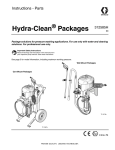
1
Instructions - Parts List
®
NXT
Two-Ball
1000cc Pumps
311833D
EN
Designed for low pressure, medium volume circulation of finishing materials.
For professional use only.
Models P06DCK, P06ECK, P06LCK, P06MCK,
P06DSG, P06ESG, P06LSG, P06MSG
620 psi (4.2 MPa, 42.7 bar) Maximum Working Pressure
100 psi (0.69 MPa, 6.9 bar) Maximum Air Inlet Pressure
Models P10DCK, P10ECK, P10LCK, P10MCK, P10LCS
1180 psi (8.14 MPa, 81.4 bar) Maximum Working Pressure
100 psi (0.69 MPa, 6.9 bar) Maximum Air Inlet Pressure
Important Safety Instructions
Read all warnings and instructions in Operation manual.
Save these instructions.
See page 2 for Table of Contents.
Patent Pending
TI8377a
II 2 G
Contents
Pumps with NXT® Air Motors Part No. Matrix . . . . 3
Warnings . . . . . . . . . . . . . . . . . . . . . . . . . . . . . . . . . 4
Installation . . . . . . . . . . . . . . . . . . . . . . . . . . . . . . . . 6
Grounding . . . . . . . . . . . . . . . . . . . . . . . . . . . . . . 6
Accessories . . . . . . . . . . . . . . . . . . . . . . . . . . . . . 6
Flush Before Using Equipment . . . . . . . . . . . . . . 7
Operation . . . . . . . . . . . . . . . . . . . . . . . . . . . . . . . . . 8
Pressure Relief Procedure . . . . . . . . . . . . . . . . . 8
Maintenance . . . . . . . . . . . . . . . . . . . . . . . . . . . . . . . 9
Shutdown . . . . . . . . . . . . . . . . . . . . . . . . . . . . . . 9
Care of the Pump . . . . . . . . . . . . . . . . . . . . . . . . 9
Flushing . . . . . . . . . . . . . . . . . . . . . . . . . . . . . . . 9
Lubrication . . . . . . . . . . . . . . . . . . . . . . . . . . . . . 9
Troubleshooting . . . . . . . . . . . . . . . . . . . . . . . . . . 11
2
Repair . . . . . . . . . . . . . . . . . . . . . . . . . . . . . . . . . . . 12
Required Tools . . . . . . . . . . . . . . . . . . . . . . . . . 12
Disconnect the Lower . . . . . . . . . . . . . . . . . . . . 12
Reconnect the Lower . . . . . . . . . . . . . . . . . . . . . 13
Models . . . . . . . . . . . . . . . . . . . . . . . . . . . . . . . . . .
P06DCK, P06ECK, P06LCK, P06MCK, . . . . .
P10DCK, P10ECK, P10LCK, P10MCK,
P10LCS . . . . . . . . . . . . . . . . . . . . . . . . . . . . 14
Parts List . . . . . . . . . . . . . . . . . . . . . . . . . . . . . . . . . 15
Dimensions . . . . . . . . . . . . . . . . . . . . . . . . . . . . . . . 16
Pump Mounting Hole Diagram . . . . . . . . . . . . . . . 17
Technical Data . . . . . . . . . . . . . . . . . . . . . . . . . . . . 18
Graco Standard Warranty . . . . . . . . . . . . . . . . . . . 20
Graco Information . . . . . . . . . . . . . . . . . . . . . . . . . 20
311833D
Pumps with NXT® Air Motors Part No. Matrix
Pumps with NXT® Air Motors Part No. Matrix
Check your pump’s identification plate (ID) for the 6-digit part number of your pump. Use the following matrix to
define the construction of your pump, based on the six digits. For example, Pump Part No. P 0 6 M S G represents
the pump (P), pressure ratio (0 6 :1), low noise exhaust motor with DataTrak™ (M), stainless steel construction (S)
PTFE/PTFE packing configuration (G). To order replacement parts, see Parts List section starting on page 15. The
digits in the matrix do not correspond to the Ref. Nos. in the Parts drawings and lists.
P
06
M
S
G
First
Digit
Second and Third
Digit
Fourth Digit
Fifth Digit
Sixth Digit
Pressure Ratio (xx:1)
P
(pumps)
311833D
Exhaust
Communication
Material
Packings
06
D
De-icing
none
C
Carbon Steel
G
PTFE / PTFE
10
E
De-icing
DataTrak
S
Stainless
Steel
K
UHMW / Leather
L
Low Noise
none
S
Severe Duty
(PTFE/UHMWP)
M
Low Noise
DataTrak
3
Warnings
Warnings
The following warnings are for the setup, use, grounding, maintenance, and repair of this equipment. The exclamation point symbol alerts you to a general warning and the hazard symbol refers to procedure-specific risk. Refer back
to these warnings. Additional, product-specific warnings may be found throughout the body of this manual where
applicable.
WARNING
EQUIPMENT MISUSE HAZARD
Misuse can cause death or serious injury.
• Do not operate the unit when fatigued or under the influence of drugs or alcohol.
• Do not exceed the maximum working pressure or temperature rating of the lowest rated system
component. See Technical Data in all equipment manuals.
• Use fluids and solvents that are compatible with equipment wetted parts. See Technical Data in all
equipment manuals. Read fluid and solvent manufacturer’s warnings. For complete information
about your material, request MSDS forms from distributor or retailer.
• Check equipment daily. Repair or replace worn or damaged parts immediately with genuine manufacturer’s replacement parts only.
• Do not alter or modify equipment.
• Use equipment only for its intended purpose. Call your distributor for information.
• Route hoses and cables away from traffic areas, sharp edges, moving parts, and hot surfaces.
• Do not kink or over bend hoses or use hoses to pull equipment.
• Keep children and animals away from work area.
• Comply with all applicable safety regulations.
TOXIC FLUID OR FUMES HAZARD
Toxic fluids or fumes can cause serious injury or death if splashed in the eyes or on skin, inhaled, or
swallowed.
• Read MSDS’s to know the specific hazards of the fluids you are using.
• Store hazardous fluid in approved containers, and dispose of it according to applicable guidelines.
• Always wear impervious gloves when spraying or cleaning equipment.
FIRE AND EXPLOSION HAZARD
Flammable fumes, such as solvent and paint fumes, in work area can ignite or explode. To help prevent
fire and explosion:
• Use equipment only in well ventilated area.
• Eliminate all ignition sources; such as pilot lights, cigarettes, portable electric lamps, and plastic drop
cloths (potential static arc).
• Keep work area free of debris, including solvent, rags and gasoline.
• Do not plug or unplug power cords, or turn power or light switches on or off when flammable fumes
are present.
• Ground all equipment in the work area. See Grounding instructions.
• Use only grounded hoses.
• Hold gun firmly to side of grounded pail when triggering into pail.
• If there is static sparking or you feel a shock, stop operation immediately. Do not use equipment
until you identify and correct the problem.
• Keep a working fire extinguisher in the work area.
4
311833D
Warnings
WARNING
PRESSURIZED EQUIPMENT HAZARD
Fluid from the gun/dispense valve, leaks, or ruptured components can splash in the eyes or on skin and
cause serious injury.
•
•
•
Follow Pressure Relief Procedure in this manual, when you stop spraying and before cleaning,
checking, or servicing equipment.
Tighten all fluid connections before operating the equipment.
Check hoses, tubes, and couplings daily. Replace worn or damaged parts immediately.
MOVING PARTS HAZARD
Moving parts can pinch or amputate fingers and other body parts.
• Keep clear of moving parts.
• Do not operate equipment with protective guards or covers removed.
• Pressurized equipment can start without warning. Before checking, moving, or servicing equipment,
follow the Pressure Relief Procedure in this manual. Disconnect power or air supply.
SKIN INJECTION HAZARD
High-pressure fluid from dispense valve, hose leaks, or ruptured components will pierce skin. This may
look like just a cut, but it is a serious injury that can result in amputation. Get immediate surgical
treatment.
• Do not point dispense valve at anyone or at any part of the body.
• Do not put your hand over the end of the dispense nozzle.
• Do not stop or deflect leaks with your hand, body, glove, or rag.
• Follow Pressure Relief Procedure in this manual, when you stop spraying and before cleaning,
checking, or servicing equipment.
311833D
5
Installation
Installation
Grounding
Solvent pails used when flushing: follow local code.
Use only conductive metal pails, placed on a grounded
surface. Do not place the pail on a nonconductive surface, such as paper or cardboard, which interrupts
grounding continuity.
The equipment must be grounded. Grounding reduces
the risk of static and electric shock by providing an
escape wire for the electrical current due to static build
up or in the event of a short circuit.
Pump: Use the ground screw (X) and lockwasher on the
motor to attach ground wire 244524 (Y). Tighten the
screw securely. Connect the other end of the ground
wire to a true earth ground.
To maintain grounding continuity when flushing or
relieving pressure: hold metal part of the spray gun
firmly to the side of a grounded metal pail, then trigger
the gun.
Accessories
Accessory Air Control Kits are available for the
NXT Air Motor. The kits include a master air valve,
air regulator, and filter. Order the kit separately.
See manual 311239 for more information.
Air Line
•
Bleed-type master air valve: required in your system to relieve air trapped between it and the air
motor when the valve is closed.
X
Y
TI8250a
FIG. 1
Air and fluid hoses: use only electrically conductive
hoses. with a maximum of 500 ft. (150 m) combined
hose length to ensure grounding continuity. Check electrical resistance of hoses. If total resistance to ground
exceeds 29 megohms, replace hose immediately.
Trapped air can cause the pump to cycle unexpectedly, which could result in serious injury from splashing
or moving parts.
Be sure the valve is easily accessible from the pump
and located downstream from the air regulator.
•
Pump air regulator: to control pump speed and
outlet pressure. Locate it close to the pump.
Air compressor: follow manufacturer’s recommendations.
•
Air line filter: removes harmful dirt and moisture
from compressed air supply.
Spray gun: ground through connection to a properly
grounded fluid hose and pump.
•
Second bleed-type air valve: isolates air line
accessories for servicing. Locate upstream from all
other air line accessories.
•
Gun air regulator: controls air pressure to the gun.
Fluid supply container: follow local code.
Object being sprayed: follow local code.
Fluid Line
•
6
Fluid filter: with a 60 mesh (250 micron) stainless
steel element to filter particles from the fluid as it
leaves the pump.
311833D
Installation
•
Fluid drain valve: required in your system, to
relieve fluid pressure in the hose and gun.
•
Fluid shutoff valve: shuts off fluid flow.
•
Fluid pressure regulator: for more precise adjustment of the fluid pressure.
•
Gun or valve: to dispense fluid.
•
Fluid line swivel: for easier gun movement.
•
Suction kit: enables the pump to draw fluid from a
container.
Flush Before Using Equipment
The equipment was tested with lightweight oil, which is
left in the fluid passages to protect parts. To avoid contaminating your fluid with oil, flush the equipment with a
compatible solvent before using the equipment. See
Flushing, page 9.
311833D
7
Operation
Operation
Pressure Relief Procedure
1. Engage trigger lock.
2. Close the bleed-type master air valve.
3. Disengage the trigger lock.
4. Hold a metal part of the gun firmly to a grounded
metal pail. Trigger the gun to relieve pressure.
5. Engage the trigger lock.
6. Open all fluid drain valves in the system, having a
waste container ready to catch drainage. Leave
drain valve(s) open until you are ready to spray
again.
7. If you suspect the spray tip or hose is clogged or
that pressure has not been fully relieved after following the steps above, VERY SLOWLY loosen tip
guard retaining nut or hose end coupling to relieve
pressure gradually, then loosen completely. Clear
hose or tip obstruction.
8
311833D
Maintenance
Maintenance
Shutdown
To reduce the risk of serious injury whenever you are
instructed to relieve pressure, always follow the Pressure Relief Procedure on page 8.
To reduce the risk of serious injury whenever you are
instructed to relieve pressure, always follow the Pressure Relief Procedure on page 8.
Always stop the pump at the bottom of its stroke to prevent fluid from drying on the rod and damaging the
throat packings.
To reduce risk of static sparking or splashing in the eyes
or on the skin, relieve the pressure and remove the
spray tip before flushing. Start the pump. Hold a metal
part of the gun firmly to the side of a grounded metal pail
and use the lowest possible fluid pressure during flushing. When flushing is complete, relieve the pressure.
Lubrication
Relieve the pressure.
Care of the Pump
On stainless steel models, check the tightness of the
packing retainer screws (A) weekly. The screws should
be tight enough to stop leakage, but no tighter. Always
relieve the pressure before adjusting the packing
retainer screws. See FIG. 2. On carbon steel models,
tighten wet cup (B) using wet cup wrench.
Carbon Steel
Stainless Steel
A
TI8336a1
B
To reduce the risk of serious injury whenever you are
instructed to relieve pressure, always follow the Pressure Relief Procedure on page 8.
The accessory air line lubricator provides automatic air
motor lubrication. For daily, manual lubrication, relieve
the pressure, disconnect the regulator, place about 15
drops of light machine oil in the pump air inlet, reconnect
the regulator, and turn on the air supply to blow oil into
the motor.
TI8337a1
FIG. 2
Flushing
If you are pumping fluid which dries, hardens, or sets
up, flush the system with a compatible solvent as often
as necessary to prevent build up of dried fluid in the
pump or hoses.
311833D
9
Maintenance
10
311833D
Troubleshooting
Troubleshooting
2. Check all possible problems and solutions before
disassembling pump.
To reduce the risk of serious injury whenever you are
instructed to relieve pressure, always follow the Pressure Relief Procedure on page 8.
1. Relieve the pressure.
PROBLEM
Pump does not operate, or no fluid flow.
Pump operates, but output is low.
Erratic or accelerated operation.
311833D
Never operate the pump with the air motor shield
removed. Moving parts can pinch or amputate your
fingers or other body parts. When the pump is operating, the air motor piston (located behind the air
motor shield) moves.
CAUSE
Loose or broken pump parts.
SOLUTION
Disassemble, check, repair.
Restricted line or inadequate air supply.
Clear, increase.
Exhausted fluid supply.
Refill and prime.
Clogged fluid hoses.
Clean, or replace.
Damaged air motor.
Repair.
Insufficient air supply.
Increase.
Exhausted fluid supply.
Refill and prime.
Obstructed gun or dispensing valve.
Clear.
Packing retainer needs adjustment.
Loosen or tighten screws as necessary.
Damaged fluid pump packings.
Replace.
Held open or worn piston intake valve.
Repair.
Exhausted fluid supply.
Refill and prime.
Fluid intake or piston valve worn.
Repair.
11
Repair
Repair
Required Tools
•
•
•
•
•
•
•
•
•
•
•
Set of socket wrenches
Set of adjustable wrenches
24 in. adjustable wrench
Torque wrench
Rubber mallet
Arbor press
Soft wooden block (approx. 1 square foot in size)
Large vise, with soft jaws
Thread lubricant
Anti-seize lubricant 222955
Loctite® 2760™ or equivalent
5. Hold the tie rod flats with a wrench to keep the rods
(6) from turning. Unscrew the nuts (7). Remove the
lower (2).
6. To service the lower, refer to manual 311716 or
311717, supplied. To service the air motor, refer to
the separate motor manual, supplied.
Disconnect the Lower
1. Flush the pump, if possible. Stop the pump at the
bottom of its stroke. Relieve the pressure, page 8.
2. Disconnect the air hose.
3. Hold the fluid outlet fitting with a wrench to keep it
from loosening while you disconnect the fluid hose.
See FIG. 3.
CAUTION
Use at least two people when lifting, moving, or disconnecting the pump. If disconnecting the lower, be
sure to securely brace the pump, or have two people
hold it while another disconnects it.
Before disconnecting the lower (2) from the motor
(1), be sure to note the relative position of the
pump's fluid outlet to the air inlet of the motor. If the
motor does not require servicing, leave it attached
to its mounting.
4. Unscrew the coupling nut (3) from the connecting
rod adapter (5). Remove the coupling collars; do not
lose or drop them. See FIG. 3.
12
311833D
Repair
Reconnect the Lower
5. Screw the nuts (7) onto the tie rods (6) and torque
as noted in FIG. 3.
1. Screw the connecting rod adapter (5) to the air
motor shaft. Torque as noted in FIG. 3.
2. Screw the tie rods (6) into the air motor (1). Using a
wrench on the tie rod flats, torque as noted.
3. Make sure the coupling nut (3) and coupling collars
(4) are in place on the displacement rod.
4. Use at least two people to hold the lower while
another reconnects it to the motor (see the CAUTION, page 12). Orient the pump's fluid outlet to the
air inlet as noted under Disconnect the Lower.
Place the lower (2) on the tie rods (6).
6. Screw the coupling nut (3) onto the connecting rod
adapter (5) loosely. Hold the connecting rod adapter
flats with a wrench to keep it from turning. Use an
adjustable wrench to tighten the coupling nut.
Torque as noted in FIG. 3.
7. Reconnect all hoses. Reconnect the ground wire if it
was disconnected. Fill the wet-cup 1/3 full of Graco
Throat Seal Liquid or compatible solvent.
8. Turn on the air power supply. Run the pump slowly
to ensure that it operates properly.
1
6
5
1
3
1
2
7
TI8363a
1
Torque to 196-210 N•m (145-155 ft-lb)
FIG. 3. Reconnect the Lower
311833D
13
Repair
Models P06DSG, P06ESG,
P06LSG, P06MSG
Models
P06DCK, P06ECK, P06LCK,
P06MCK,P10DCK, P10ECK,
P10LCK, P10MCK, P10LCS
1
1
15
15
6
6
5
5
4
4
3
7
3
7
2
2
TI8334a
TI8335a
FIG. 4
FIG. 5
14
311833D
Parts List
Parts List
Ref.
Description
1
2
3
4
5
6
7
15
17
MOTOR, 3400, de-icing std; see manual 311238
MOTOR, 3400, de-icing datatrak; see manual 311238
MOTOR, 3400, low noise std; see manual 311238
MOTOR, 3400, low noise datatrak; see manual 311238
PUMP; see manual 311716
NUT, coupling
COLLAR, coupling
ADAPTER
ROD, tie
NUT, lock
PLUG, pipe, round
WRENCH, wet cup
Ref.
Description
1
MOTOR, 3400, de-icing std; see manual 311238
MOTOR, 3400, de-icing datatrak; see manual 311238
MOTOR, 3400, low noise std; see manual 311238
MOTOR, 3400, low noise datatrak; see manual 311238
PUMP; see manual 311717
NUT, coupling
COLLAR, coupling
ADAPTER
ROD, tie
NUT, lock
PLUG, pipe, round
WRENCH, wet cup
2
3
4
5
6
7
15
17
Ref.
Description
1
MOTOR, 6500, de-icing std; see manual 311238
MOTOR, 6500, de-icing datatrak; see manual 311238
MOTOR, 6500, low noise std; see manual 311238
MOTOR, 6500, low noise datatrak; see manual 311238
PUMP; see manual 311717
NUT, coupling
COLLAR, coupling
ADAPTER
ROD, tie
NUT, lock
PLUG, pipe, round
2
3
4
5
6
7
15
311833D
P06DSG
P06ESG
P06LSG
P06MSG
Qty.
N34DN0
1
1
1
1
1
1
2
1
3
3
1
1
N34DT0
N34LN0
253596
184096
184130
15H371
15H562
101712
120588
184278
P06DCK
253596
184096
184130
15H371
15H562
101712
120588
184278
P06ECK
253596
184096
184130
15H371
15H562
101712
120588
184278
P06LCK
N34LT0
253596
184096
184130
15H371
15H562
101712
120588
184278
P06MCK
Qty.
N34DN0
N34DT0
N34LN0
253597
184096
184130
15H371
15H562
101712
120588
184278
P10DCK
253597
184096
184130
15H371
15H562
101712
120588
184278
P10ECK
253597
184096
184130
15H371
15H562
101712
120588
184278
P10LCK
N34LT0
253597
184096
184130
15H371
15H562
101712
120588
184278
P10MCK
P10LCS
N65DN0
N65DT0
N65LN0
253597
184096
184130
15H371
15H562
101712
120588
253597
184096
184130
15H371
15H562
101712
120588
253597
184096
184130
15H371
15H562
101712
120588
N65LN0
N65LT0
253597
184096
184130
15H371
15H562
101712
120588
1
1
1
1
1
1
2
1
3
3
1
1
L10XCS
184096
184130
15H371
15H562
101712
120588
Qty.
1
1
1
1
1
1
2
1
3
3
1
15
Dimensions
Dimensions
A
B
TI8377a
Pump Model
P06_SG
P06_CK
P10_CK
P10_CS
16
A
in. (mm)
41.6 (1055)
41.6 (1055)
41.6 (1055)
41.6 (1055)
B
in. (mm)
28.0 (711)
28.0 (711)
28.0 (711)
28.0 (711)
Approx.
Weight
lb (kg)
113 (51)
113 (51)
132 (62)
132 (62)
311833D
Pump Mounting Hole Diagram
Pump Mounting Hole Diagram
NXT Model 3400
Four 3/8-16
Mounting Holes
6.186 in.
(157 mm)
Six 5/8-11
Tie Rod Holes
6.186 in.
(157 mm)
TI8070A
NXT Model 6500
Four 3/8-16
Mounting Holes
101.6 mm
(4.0 in.)
6.180 in.
(157 mm)
Three 5/8-11
Tie Rod Holes
6.180 in.
(157 mm)
TI8069A
311833D
17
Technical Data
Technical Data
Model
All P06 _ _ _ Models
Maximum
Working Pressure
psi (MPa, bar)
Maximum
Air Input Pressure
psi (MPa, bar)
620 (4.2, 42)
100 (0.69, 6.9)
Fluid Flow at
60 cycles per minute
gpm (lpm)
Air Consumption
17.4 (65.8)
See Performance Chart
All P10 _ _ _ Models
1180 (8.14, 81.4)
100 (0.69, 6.9)
17.4 (65.8)
See air motor manual 311238 for sound pressure levels.
Pump Performance Charts
Fluid Outlet Pressure
To find fluid outlet pressure (MPa/bar/psi) at a specific flow
(lpm/gpm) and operating pressure (A/B/C):
1.
Locate desired flow at bottom of chart.
2.
Follow vertical line up to intersection with selected operating pressure curve (solid line). Follow left to scale to read
fluid outlet pressure.
Key
A
0.7 MPa, 7 bar (100 psi) air pressure or 10.5 MPa, 105 bar (1500 psi) hydraulic oil pressure
B
0.5 MPa, 4.9 bar (70 psi) air pressure or 7.5 MPa, 75 bar (1050 psi) hydraulic oil pressure
C
0.3 MPa, 2.8 bar (40 psi) air pressure or 4.2 MPa, 42 bar (600 psi) hydraulic oil pressure
Test Fluid: No. 10 Weight Oil
Stainless Steel 1000cc Pump with NXT Model 3400 Air Motor
psi (MPa, bar)
700 (4.8, 48)
140
A
600 (4.1, 41)
120
A
Fluid Pressure
B
400 (2.7, 27)
80
B
300 (2.0, 20)
200 (1.3, 13)
100
C
60
Air Flow (scfm)
500 (3.4, 34)
40
C
100 (6.8, 68)
20
0
4.0 6.0 8.0 10.0 12.0 14.0 16.0 18.0
2.0
(7.5) (11.3) (15.1) (18.9) (40.8)(40.8) (54.5) (54.5) (68.1)
Fluid Flow in gpm (lpm)
18
311833D
Technical Data
Key
A
0.7 MPa, 7 bar (100 psi) air pressure or 10.5 MPa, 105 bar (1500 psi) hydraulic oil pressure
B
0.5 MPa, 4.9 bar (70 psi) air pressure or 7.5 MPa, 75 bar (1050 psi) hydraulic oil pressure
C
0.3 MPa, 2.8 bar (40 psi) air pressure or 4.2 MPa, 42 bar (600 psi) hydraulic oil pressure
Test Fluid: No. 10 Weight Oil
Carbon Steel 1000cc Pump with NXT Model 3400 Air Motor
psi (MPa, bar)
700 (4.8, 48)
120
A
600 (4.1, 41)
100
A
Fluid Pressure
B
80
400 (2.7, 27)
B
300 (2.0, 20)
60
C
Air Flow (scfm)
500 (3.4, 34)
40
200 (1.3, 13)
C
20
100 (6.8, 68)
0
4.0 6.0 8.0 10.0 12.0 14.0 16.0 18.0
2.0
(7.5) (11.3) (15.1) (18.9) (40.8)(40.8) (54.5) (54.5) (68.1)
Fluid Flow in gpm (lpm)
Carbon Steel 1000cc Pump with NXT Model 6500 Air Motor
psi (MPa, bar)
140
1400 (9.6, 96)
120
1200 (8.2, 82)
A
Fluid Pressure
800 (5.5, 55)
B
80
B
60
600 (4.1, 41)
C
400 (2.7, 27)
C
40
20
200 (1.3, 13)
0
100
Air Flow (scfm)
A
1000 (6.8, 68)
4.0 6.0 8.0 10.0 12.0 14.0 16.0 18.0
2.0
(7.5) (11.3) (15.1) (18.9) (40.8)(40.8) (54.5) (54.5) (68.1)
Fluid Flow in gpm (lpm)
311833D
19
Graco Standard Warranty
Graco warrants all equipment referenced in this document which is manufactured by Graco and bearing its name to be free from defects in
material and workmanship on the date of sale to the original purchaser for use. With the exception of any special, extended, or limited warranty
published by Graco, Graco will, for a period of twelve months from the date of sale, repair or replace any part of the equipment determined by
Graco to be defective. This warranty applies only when the equipment is installed, operated and maintained in accordance with Graco’s written
recommendations.
This warranty does not cover, and Graco shall not be liable for general wear and tear, or any malfunction, damage or wear caused by faulty
installation, misapplication, abrasion, corrosion, inadequate or improper maintenance, negligence, accident, tampering, or substitution of
non-Graco component parts. Nor shall Graco be liable for malfunction, damage or wear caused by the incompatibility of Graco equipment with
structures, accessories, equipment or materials not supplied by Graco, or the improper design, manufacture, installation, operation or
maintenance of structures, accessories, equipment or materials not supplied by Graco.
This warranty is conditioned upon the prepaid return of the equipment claimed to be defective to an authorized Graco distributor for verification of
the claimed defect. If the claimed defect is verified, Graco will repair or replace free of charge any defective parts. The equipment will be returned
to the original purchaser transportation prepaid. If inspection of the equipment does not disclose any defect in material or workmanship, repairs
will be made at a reasonable charge, which charges may include the costs of parts, labor, and transportation.
THIS WARRANTY IS EXCLUSIVE, AND IS IN LIEU OF ANY OTHER WARRANTIES, EXPRESS OR IMPLIED, INCLUDING BUT NOT
LIMITED TO WARRANTY OF MERCHANTABILITY OR WARRANTY OF FITNESS FOR A PARTICULAR PURPOSE.
Graco’s sole obligation and buyer’s sole remedy for any breach of warranty shall be as set forth above. The buyer agrees that no other remedy
(including, but not limited to, incidental or consequential damages for lost profits, lost sales, injury to person or property, or any other incidental or
consequential loss) shall be available. Any action for breach of warranty must be brought within two (2) years of the date of sale.
GRACO MAKES NO WARRANTY, AND DISCLAIMS ALL IMPLIED WARRANTIES OF MERCHANTABILITY AND FITNESS FOR A
PARTICULAR PURPOSE, IN CONNECTION WITH ACCESSORIES, EQUIPMENT, MATERIALS OR COMPONENTS SOLD BUT NOT
MANUFACTURED BY GRACO. These items sold, but not manufactured by Graco (such as electric motors, switches, hose, etc.), are subject to
the warranty, if any, of their manufacturer. Graco will provide purchaser with reasonable assistance in making any claim for breach of these
warranties.
In no event will Graco be liable for indirect, incidental, special or consequential damages resulting from Graco supplying equipment hereunder, or
the furnishing, performance, or use of any products or other goods sold hereto, whether due to a breach of contract, breach of warranty, the
negligence of Graco, or otherwise.
FOR GRACO CANADA CUSTOMERS
The Parties acknowledge that they have required that the present document, as well as all documents, notices and legal proceedings entered into,
given or instituted pursuant hereto or relating directly or indirectly hereto, be drawn up in English. Les parties reconnaissent avoir convenu que la
rédaction du présente document sera en Anglais, ainsi que tous documents, avis et procédures judiciaires exécutés, donnés ou intentés, à la suite
de ou en rapport, directement ou indirectement, avec les procédures concernées.
Graco Information
For the latest information about Graco products, visit www.graco.com.
For patent information, see www.graco.com/patents.
TO PLACE AN ORDER, contact your Graco distributor or call to identify the nearest distributor.
Phone: 612-623-6921 or Toll Free: 1-800-328-0211 Fax: 612-378-3505
All written and visual data contained in this document reflects the latest product information available at the time of publication.
Graco reserves the right to make changes at any time without notice.
Original instructions. This manual contains English. MM 311833
Graco Headquarters: Minneapolis
International Offices: Belgium, China, Japan, Korea
GRACO INC. AND SUBSIDIARIES • P.O. BOX 1441 • MINNEAPOLIS MN 55440-1441 • USA
Copyright 2006, Graco Inc. All Graco manufacturing locations are registered to ISO 9001.
www.graco.com
Revision D, September 2014