1
Installation
E-Flo® 4-Ball
Piston Pumps
311592V
EN
Durable, energy efficient piston pumps for high volume paint circulation applications.
For professional use only.
See page 3 for model information, including maximum working pressure. See page 5 for approvals.
Important Safety Instructions
Read all warnings and instructions in this manual.
Save these instructions.
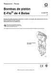
E-Flo 4000 Pump Shown
ti8317c
Related Manuals
Contents
Related Manuals . . . . . . . . . . . . . . . . . . . . . . . . . . . 2
Models . . . . . . . . . . . . . . . . . . . . . . . . . . . . . . . . . . . 3
E-Flo 4-Ball Piston Pumps . . . . . . . . . . . . . . . . . 3
Maximum Working Pressure and Pump Operational
Limits . . . . . . . . . . . . . . . . . . . . . . . . . . . . . . 3
Approvals . . . . . . . . . . . . . . . . . . . . . . . . . . . . . . . . . 5
Warnings . . . . . . . . . . . . . . . . . . . . . . . . . . . . . . . . . 6
System Components . . . . . . . . . . . . . . . . . . . . . . . . 8
Hazardous Area . . . . . . . . . . . . . . . . . . . . . . . . . 8
Non-Hazardous Area . . . . . . . . . . . . . . . . . . . . . 8
System Wiring Schematics . . . . . . . . . . . . . . . . . . 10
Power Supply Requirements . . . . . . . . . . . . . . . . 13
Power Disconnect Switch . . . . . . . . . . . . . . . . . 13
Hazardous Area Cabling and Conduit Requirements
(Explosion Proof) . . . . . . . . . . . . . . . . . . . . 13
Increased Safety (European) . . . . . . . . . . . . . . 13
16D612 Power Module . . . . . . . . . . . . . . . . . . . 13
Pressure Transducer Grounding Requirements 14
IS Field Wiring Grounding Requirements . . . . . 14
Pump Location . . . . . . . . . . . . . . . . . . . . . . . . . . . . 15
Environmental Conditions . . . . . . . . . . . . . . . . . 15
Clearance . . . . . . . . . . . . . . . . . . . . . . . . . . . . . 15
15H884 Floor Stand . . . . . . . . . . . . . . . . . . . . . 15
Connect Fluid Lines . . . . . . . . . . . . . . . . . . . . . . . . 15
Electric Motor . . . . . . . . . . . . . . . . . . . . . . . . . . . . . 16
Electric Motor Specifications . . . . . . . . . . . . . . . 16
Motor Wiring . . . . . . . . . . . . . . . . . . . . . . . . . . . 16
Install the Motor . . . . . . . . . . . . . . . . . . . . . . . . . 17
Electrical Noise Filter . . . . . . . . . . . . . . . . . . . . . . 19
Variable Frequency Drive Accessory (VFD) . . . . 20
VFD Installation . . . . . . . . . . . . . . . . . . . . . . . . . 20
VFD Wiring . . . . . . . . . . . . . . . . . . . . . . . . . . . . 20
ACS Module (Optional) . . . . . . . . . . . . . . . . . . . . . 20
ACS Wiring . . . . . . . . . . . . . . . . . . . . . . . . . . . . 20
Ethernet Interface (optional) . . . . . . . . . . . . . . . . . 20
Local Control Box (optional accessory) . . . . . . . 21
Pneumatic Back Pressure Regulator (optional) . 22
Dimensions . . . . . . . . . . . . . . . . . . . . . . . . . . . . . . . 24
Technical Data . . . . . . . . . . . . . . . . . . . . . . . . . . . . 26
Graco Standard Warranty . . . . . . . . . . . . . . . . . . . 28
Graco Information . . . . . . . . . . . . . . . . . . . . . . . . . 28
Related Manuals
Manual
311593
311594
311595
311596
311603
3A0539
3A0006
2
Description
E-Flo Operation Manual
E-Flo Repair-Parts Manual
Pneumatic Back Pressure Regulator
Variable Frequency Drive Instructions
Sensor Circuit Option
4-Ball Lowers
ACS Module
311592V
Models
Models
E-Flo 4-Ball Piston Pumps
Check your pump’s identification plate (ID) for the 6-digit part number of your
pump. Use the following matrix to define the construction of your pump, based
on the six digits. For example, Pump Part No. E P 2 1 6 0 represents electric
power (E), pump (P), 230/460V motor (2), sensor circuit installed (1), 2000 cc
MaxLife lower (6), and no stand installed (0). To order replacement parts, see
the Repair-Parts manual 311594.
ID
ti8912a
E
P
2
1
6
0
First Digit
Second Digit
Third Digit
Fourth Digit
Fifth Digit
Sixth Digit
Power
Source
Equipment
Style
E (electric) P (pump)
Motor
Sensor Circuit
0
No motor
0
1
230/400V, 5
HP, ATEX
230/460V, 5
HP, UL/CSA
230/400V, 3
HP, ATEX
230/460V, 3
HP, UL/CSA
1
2
3
4
No circuit
installed
Circuit installed
Lower Size
Stand Option
1
1000 cc Chrome
0
2
1500 cc Chrome
1
3
2000 cc Chrome
4
1000 cc MaxLife®
5
1500 cc MaxLife
6
7
8
2000 cc MaxLife
750 cc Chrome
750 cc MaxLife
No stand
installed
Stand
installed
Maximum Working Pressure and Pump Operational Limits
E-Flo 1500: 425 psi (2.93 MPa, 29.3 bar) Maximum Working Pressure
E-Flo 2000: 460 psi (3.22 MPa, 32.2 bar) Maximum Working Pressure
E-Flo 3000: 330 psi (2.31 MPa, 23.1 bar) Maximum Working Pressure
E-Flo 4000: 250 psi (1.75 MPa, 17.5 bar) Maximum Working Pressure
See Technical Data, page 26, for pump operational limits.
311592V
3
Models
4
311592V
Approvals
Approvals
The E-Flo Pump meets requirements of the following approval agencies.
Refer to the individual components for other specific hazardous location listings.
Component
Part No.
Approvals
Mechanical Pump
c T3
ATEX
EP1XXX
EP3XXX
Ex de IIC T4 - CESI 05 ATEX 110X
Motor
UL/CSA
EP2XXX
Class I, Group D, Class II, Group F and G, Division 1,
T3B Hazardous Locations
EP4XXX
Class 1, Div. 1, Group C & D T3 Hazardous Locations
IS Sensor Circuit
EPX1XX
EEx ib IIB Ta = 0°C - 50°C - FM 06 ATEX 0025U
Ex ib IIB Ta = 0°C - 50°C - KTL 13-KB4BO-0088
311592V
5
Warnings
Warnings
The following warnings are for the setup, use, grounding, maintenance, and repair of this equipment. The exclamation point symbol alerts you to a general warning and the hazard symbols refer to procedure-specific risks. When
these symbols appear in the body of this manual, refer back to these Warnings. Product-specific hazard symbols and
warnings not covered in this section may appear throughout the body of this manual where applicable.
WARNING
FIRE AND EXPLOSION HAZARD
Flammable fumes, such as solvent and paint fumes, in work area can ignite or explode. To help prevent
fire and explosion:
• Use equipment only in well ventilated area.
• Eliminate all ignition sources; such as pilot lights, cigarettes, portable electric lamps, and plastic drop
cloths (potential static arc).
• Keep work area free of debris, including solvent, rags and gasoline.
• Do not plug or unplug power cords, or turn power or light switches on or off when flammable fumes are
present.
• Ground all equipment in the work area. See Grounding instructions.
• Use only grounded hoses.
• Hold gun firmly to side of grounded pail when triggering into pail.
• If there is static sparking or you feel a shock, stop operation immediately. Do not use equipment until
you identify and correct the problem.
• Keep a working fire extinguisher in the work area.
Static charge may build up on plastic parts during cleaning and could discharge and ignite flammable
vapors. To help prevent fire and explosion:
•
Clean plastic parts only in a well ventilated area.
•
Do not clean with a dry cloth.
•
Do not operate electrostatic guns in equipment work area.
EQUIPMENT MISUSE HAZARD
Misuse can cause death or serious injury.
• Do not operate the unit when fatigued or under the influence of drugs or alcohol.
• Do not exceed the maximum working pressure or temperature rating of the lowest rated system component. See Technical Data in all equipment manuals.
• Use fluids and solvents that are compatible with equipment wetted parts. See Technical Data in all
equipment manuals. Read fluid and solvent manufacturer’s warnings. For complete information about
your material, request MSDS forms from distributor or retailer.
• Check equipment daily. Repair or replace worn or damaged parts immediately with genuine manufacturer’s replacement parts only.
• Do not alter or modify equipment.
• Use equipment only for its intended purpose. Call your distributor for information.
• Route hoses and cables away from traffic areas, sharp edges, moving parts, and hot surfaces.
• Do not kink or over bend hoses or use hoses to pull equipment.
• Keep children and animals away from work area.
• Comply with all applicable safety regulations.
6
311592V
Warnings
WARNING
ELECTRIC SHOCK HAZARD
Improper grounding, setup, or usage of the system can cause electric shock.
• Turn off and disconnect power at main switch before disconnecting any cables and before servicing
equipment.
• Connect only to grounded power source.
• All electrical wiring must be done by a qualified electrician and comply with all local codes and
regulations.
PRESSURIZED EQUIPMENT HAZARD
Fluid from the gun/dispense valve, leaks, or ruptured components can splash in the eyes or on skin and
cause serious injury.
• Follow Pressure Relief Procedure in this manual, when you stop spraying and before cleaning,
checking, or servicing equipment.
• Tighten all fluid connections before operating the equipment.
• Check hoses, tubes, and couplings daily. Replace worn or damaged parts immediately.
MOVING PARTS HAZARD
Moving parts can pinch or amputate fingers and other body parts.
• Keep clear of moving parts.
• Do not operate equipment with protective guards or covers removed.
• Pressurized equipment can start without warning. Before checking, moving, or servicing equipment,
follow the Pressure Relief Procedure in this manual. Disconnect power or air supply.
TOXIC FLUID OR FUMES HAZARD
Toxic fluids or fumes can cause serious injury or death if splashed in the eyes or on skin, inhaled, or swallowed.
• Read MSDS’s to know the specific hazards of the fluids you are using.
• Store hazardous fluid in approved containers, and dispose of it according to applicable guidelines.
• Always wear impervious gloves when spraying or cleaning equipment.
PERSONAL PROTECTIVE EQUIPMENT
You must wear appropriate protective equipment when operating, servicing, or when in the operating area
of the equipment to help protect you from serious injury, including eye injury, inhalation of toxic fumes,
burns, and hearing loss. This equipment includes but is not limited to:
• Protective eyewear
• Clothing and respirator as recommended by the fluid and solvent manufacturer
• Gloves
• Hearing protection
BURN HAZARD
Equipment surfaces and fluid that’s heated can become very hot during operation. To avoid severe burns,
do not touch hot fluid or equipment. Wait until equipment/fluid has cooled completely.
311592V
7
System Components
System Components
Schedule of Limitations
ATEX:
1. After the installation of the Electric Circulation
Pump Control into an enclosure the creepage
and clearance distances shall meet the requirements of 6.4 (Table 4) of EN50020.
FIG. 1 illustrates a typical North American system installation, showing the major system components. Also see
the wiring schematic in FIG. 2 and FIG. 3.
Hazardous Area
2. After the installation of the Electric Circulation
Pump Control into an enclosure the assembly
shall be capable of withstanding an r.m.s. a.c.
test voltage of twice the voltage of the intrinsically safe circuit or 500 V, whichever is the
greater.
Do not install equipment approved only for non-hazardous locations in a hazardous area.
See FIG. 1. The following system components are
approved for use in a hazardous area:
Sensor Circuit Wetted Parts
Pressure transducer: 17-4 PH stainless steel
•
E-Flo Electric Circulation Pump
•
Explosion-Proof Electric Motor
•
Local Control Box (accessory)
Non-Hazardous Area
•
Pneumatic Back Pressure Regulator (accessory)
See FIG. 1. Install the following components in a
non-hazardous area:
•
Sensor Control Circuit (option). See intrinsic safety
installation requirements below.
NOTE: All other components shown in FIG. 1 must be
installed in a non-hazardous area.
•
System Power Disconnect Switch
•
Electrical Noise Filter (accessory)
•
Variable Frequency Drive (accessory)
•
Power Module (accessory)
•
3-Way Pneumatic Solenoid Valve (accessory)
293140l
8
311592V
System Components
Non-Hazardous Area
F
D
E
H
V
Hazardous Area
N M
M C
B
W
A
Z
AB
AA
S
AC
Y
L
AD
T
U
X
G
Hazardous
Area
Entrance
K
J
R
P
AD
ti8651c
Non-Hazardous Area
Hazardous Area
FIG. 1: Typical Installation
Key:
A
E-Flo Electric Circulation Pump
B*
C*
D*
E**
F*
G*
H*
J**
K**
L**
M**
N**
P*
R**
S**
Explosion-Proof Electric Motor
Local Control Box
Variable Frequency Drive (VFD)
System Power Disconnect Switch
Electrical Noise Filter
Power Module
VFD/BPR Pneumatic Control Kit
Electric Power Cable, VFD to Electric Motor
Electric Control Cable, Local Control Box to VFD
Explosion-Proof Seal Fittings
Electric IS Control Cable, Power Module to Pump Sensor
Circuit
Electric Cable, VFD to 3-Way Solenoid Valve (2 meters
provided by Graco)
Pump Stand
Fluid Inlet Line
Fluid Outlet Line
311592V
T** Fluid Return Line
U* Pneumatic Back Pressure Regulator
V** Air Supply Lines to 3-Way Solenoid Valve
W** Air Line, Solenoid Valve to Back Pressure Regulator
X** Ethernet Cable, VFD to Computer
Y** Personal Computer
Z** Pump Ground Wire
AA* Explosion-Proof Electric Agitator
AB** Pressure Relief
AC* Fluid Filters
AD* Fluid Line Isolation Valves
* Option available from Graco.
** Supplied by integrator.
9
System Wiring Schematics
System Wiring Schematics
For use with Variable Frequency Drive (VFD) Accesory
FIG. 2 shows components that must be installed in a
non-hazardous location.
FIG. 3 shows components approved for installation in a
hazardous location, and FIG. 4 shows detail views of
hazardous location components.
NON-HAZARDOUS AREA
1
12 Gauge Alpha Wire P/N V16012/equiv.
2
16 Gauge MTW Wire.
3
Blue/White 16 Gauge MTW Wire.
4
Blue 16 Gauge MTW Wire.
NON-HAZARDOUS AREA
TERMINAL BLOCKS
4
4
BREAKING
RESISTOR
200/230 VAC - (120363)
400/460 VAC - (120364)
A
A
24V (+)
A
A
1
1
COM (-)
1
1
1
1
COM (-)
1
1
3
VARIABLE FREQUENCY DRIVE
200/230 VAC - (120361)
400/460 VAC - (120362)
ETHERNET
TCP/IP
MODULE
(120368)
APPLICATIONS
LITE
MODULE
(120367)
PE L1 L2 L3
1
U
V
W GND
1
2
3 GND
1
2
3
4
5
6
7
8
9
10
11
COM
EXTERNAL 24 VDC
COM
INTERNAL 10 VDC
DIFF. ANALOG INPUT (+)
DIFF. ANALOG INPUT (-)
ANALOG IN #2
MOTOR THERMISTOR
OPEN
OPEN
COM
21
22
23
24
25
26
27
28
29
30
31
COM
INTERNAL 24 VDC
OPEN
TDC SENSOR
TRIP RESET
BPR SOLENOID
RUN/STOP
LOCAL REMOTE
JOG
OPEN
SECURE DISABLE
41
42
OPEN
OPEN
15 BARRIER
14 (16A630)
ALL SWITCHES
9 "ON" POSITION 1
1
15
14
7
8
1
2
3
4
I.S.
ACTIVE
BARRIER
(16A633)
3
3
4
3
BPR
SOLENOID
4
COM
25
26
27
28
29
31
22
TERMINAL
BLOCKS
25
26
27
28
29
31
22
+24 VDC
POWER
SUPPLY
(120369)
4
TRIP RESET
RUN/STOP
LOCAL REMOTE
JOG
SECURE DISABLE
24V (+)
EXPLOSION
PROOF SEAL
FITTING
EXPLOSION PROOF CONDUIT BETWEEN LOCAL
CONTROL BOX AND EXPLOSION PROOF SEAL FITTING.
CLASS I, DIV. I, GROUP C & D APPROVED.
L N
EXPLOSION
PROOF SEAL
FITTING
2
PE L1 L2 L3
RFI FILTER
200/230 VAC - (120365)
400/460 VAC - (120366)
L1
PE
L2
L3
FUSE 1
FUSE 3
FUSE 2
H1 TRANSFORMER
H2 (400/460 VOLT
H3 SYSTEMS ONLY)
H4
X1
XF
X2
2
EXPLOSION PROOF CONDUIT BETWEEN MOTOR
JUNCTION BOX AND EXPLOSION PROOF SEAL FITTING.
CLASS I, DIV. I, GROUP C & D APPROVED.
TERMINAL
BLOCKS
L3
L3
L2
L2
L1
L1
PE
SUPPLY
GRND
1
3
3
LINE POWER (IN)
, 60 Hz, 230/460 VAC
, 50 Hz, 200/400 VAC
IS Control Drawing 288110
1
FIG. 2: System Wiring Schematic, Non-Hazardous Location Only
10
311592V
System Wiring Schematics
6
Alpha Wire P/N M16107LW/equiv.
SEE DETAIL A,
page
SEE 12
SHEET 1 DETAIL
HAZARDOUS AREA
POSITION SENSOR
(16K088)
GREEN
J2
3
4
BLACK
J3
1
2
3
RED
BLACK
1
2
IS SENSOR
CIRCUIT
BOARD
(249639)
1
2
3
4
5
J2
TDC
NAMUR
SENSOR
(15H984)
J1
PRESSURE
TRANSDUCER
(120371)
6
LOCAL CONTROL
(120373)
COM
TRIP RESET
RUN/STOP
LOCAL/REMOTE
JOG
SECURE DISABLE
24V (+)
BLU - 18 GA MTW WIRE
BLU - 18 GA MTW WIRE
GRN/YLW - 14 GA ALPHA WIRE P/N: V16014/EQUIV.
BLK - 14 GA ALPHA WIRE P/N: V16014/EQUIV.
BLK - 14 GA ALPHA WIRE P/N: V16014/EQUIV.
BLK - 14 GA ALPHA WIRE P/N: V16014/EQUIV.
SEE DETAIL
B, page 12
IS Control Drawing 288110
FIG. 3: System Wiring Schematic, Hazardous Location
311592V
11
System Wiring Schematics
DETAIL A
HAZARDOUS (CLASSIFIED) LOCATION
CLASS I, DIV. 1, GROUP C & D, T3 (FM ONLY)
GROUP II, CATEGORY 2 - ZONE 1, GAS (ATEX ONLY)
CLASS I, DIV. 1, GROUP C & D T3 (CANADA)
INSTALLED ON PUMP ASSEMBLY
NON-HAZARDOUS
AREA
INSTALLED IN E-FLO JUNCTION BOX ONLY
(16J588)
+(BRN)
2
BARRIER
(16A630)
ALL SWITCHES
"ON" POSITION 1
BARRIER
(16A633)
1
GREEN
3
BLACK
1
2
3
4
RED
BLACK
J2
J3
3
4
1
2
3
1
2
IS SENSOR
CIRCUIT
BOARD
(249639)
J2
1
2
3
4
5
POSITION SENSOR
(16K088)
-(BLU)
TDC
NAMUR
SENSOR
(15H984)
+ (BRN)
- (BLU)
J1
(RED)
(GRN)
(WHT)
(BLK)
PRESSURE
TRANSDUCER
(120371)
5
FERRITE
(16G496)
BELDEN 8777 OR EQUIV.
WITH FERRITE (123375)
1
1$085%$55,(5
7'&326,7,216(1625&,5&8,7
8L 9
,L P$
3L P:
&L Q)
/L X+
The installation must meet the requirements of the National Electric Code,
Canadian Electrical Code Part I, Article 504, NFPA 70, and ANSI/ISA 12.06.01.
2
Individually shielded cables needed to ensure separation of sensor and
transducer circuits.
3
The voltage (Vmax or Ui), current (Imax or Ii), and power (Pi) must be equal to or
greater than the voltage (Voc, Uo, or Vt), current (Isc, Io, or It), and power (Po or
Pt) levels, which can be delivered by the associated apparatus. In addition, the
maximum unprotected capacitance (Ci) and inductance (Li) of the intrinsically
safe apparatus, including interconnecting wiring, must be less than the
capacitance (Ca) and inductance (La) which can be safely connected to the
associated apparatus.
5
$&7,9(%$55,(5
35(6685(75$16'8&(5&,5&8,7
8L 9
,L P$
3L :
&L X)
/L X+
Land shield drain and foil to conductive strain relief.
DETAIL B
3
HAZARDOUS AREA
M
M
8/(;3/26,213522)02725
-9$&8/
$7(;(;3/26,213522)02725
31-9$&
02725-81&7,21%2;
02725-81&7,21%2;
/2:92/7$*(9 25
7
29(57(03
6:,7&+
3
SEE PAGE 11
3
7
7
7
7
7
+,*+92/7$*(9
7
7
7
7
7
/2:92/7$*(9
7
7
7
7
7
7
7
:
8
%/8*$07::,5(
%/8*$07::,5(
*51</:*$$/3+$:,5(319(48,9
%/.*$$/3+$:,5(319(48,9
%/.*$$/3+$:,5(319(48,9
%/.*$$/3+$:,5(319(48,9
9
+,*+92/7$*(9 37&
:
8
9
*51'
*51'
*1'
6((6+((7
8
9
:
8
9
:
*1'
IS Control Drawing 288110
FIG. 4: System Wiring Schematic, Hazardous Location Detail Views
12
311592V
Power Supply Requirements
Power Supply Requirements
Improper wiring may cause electric shock or other
serious injury if work is not performed properly. Have
a qualified electrician perform any electrical work. Be
sure your installation complies with all National, State
and Local safety and fire codes.
See TABLE 1 for power supply requirements. The system requires a dedicated circuit protected with a 20 A
circuit breaker.
Table 1: Power Supply Specifications
Voltage
230/400V
230/460V
Phase
Hz
Minimum Circuit
Breaker Size
3
3
50/60
50/60
20 A/15 A
20 A/15 A
Power Disconnect Switch
See FIG. 1 on page 9. Install a power disconnect switch
(E) in the non-hazardous area. This switch must shut off
and lock-out all electric power to the system.
Hazardous Area Cabling and
Conduit Requirements
(Explosion Proof)
All non-intrisically safe wiring in the hazardous area
must be encased in Class I, Division I, Group C and D
approved explosion-proof conduit.
Wire passages from the hazardous to the non-hazardous area must be secured by explosion-proof seal fittings (L).
Increased Safety (European)
Use appropriate cables, connectors, and cable glands
rated for ATEX II 2 G. Follow all National and Local electric codes.
Table 2: Cabling Specifications
Connection Points
VFD to Motor
Motor Overtemperature Switch to VFD
Local Control Box to
VFD
Wire Size,
AWG (mm2)
Maximum
Length
ft (m)
14 (2.5)
18 (0.75)
330 (100)
330 (100)
16 (1.5)
330 (100)
16D612 Power Module
The 16D612 Power Module transforms the high voltage
power supply to a 24 Vdc input for the pump sensor circuit. See manual 311608 for further information.
See FIG. 1 on page 9. Install the power module (G) in
the non-hazardous area.
See FIG. 2 Electrical Schematic for module wiring connections.
311592V
13
Power Supply Requirements
Pressure Transducer Grounding
Requirements
IS Field Wiring Grounding
Requirements
The pressure transducer cable (25a) shield and drain
wire is grounded through metal-to-metal contact with the
transducer conductive strain relief (35). See FIG. 5.
The IS field wire is grounded through the grounding
screw in the junction box. See FIG. 6.
Ensure that the conductive strain relief (35) is screwed
tightly into the housing, to ensure electrical continuity to
the pump housing.
Tighten the nut (N) on the conductive strain relief (35)
securely to ensure that the shield and drain wire (G) has
firm metal-to-metal contact between the nut and bushing
(B). Ensure that the ferrite (76) is attached around the
transducer leadwires, and is located inside the circuit
board compartment.
Ensure that the conductive strain relief (74a) is screwed
tightly into the housing. Units with a sensor circuit must
use the conductive strain relief to ensure proper shielding of the IS field wire.
Thread the IS field wire through the conductive strain
relief (74a) and connect it to J2 and J3 on the circuit
board. See FIG. 6 and the System Wiring Schematics,
page 11.
See FIG. 6. Tighten the nut (N) on the conductive strain
relief (74a) securely. Install the ferrite (77) on the field
wire (F), not more than 2 in. (51 mm) from the bottom of
the conductive strain relief (74a). Install ground wire (G)
to grounding screw in junction box.
76
N
74a
25a
B
3
35
3
B
G
Tighten nut (N) securely to
ensure that the shield and
drain wire (G) has firm
metal-to-metal contact
between the nut and
bushing (B).
Not more than
2 in. (51 mm)
77
F
G
N
44
ti16891b
ti16890b
FIG. 6. IS Circuit Field Wire
-
%51
%/8
-
-
-
,66(1625
&,5&8,7
%2$5'
-
)(55,7(
*
5
7'&
1$085
6(1625
%51
%/8
326,7,21
6(1625
5('
*51
:+7
%/.
35(6685(
75$16'8&(5
ti17644a
Land shield drain and foil to conductive strain relief.
FIG. 5. Transducer Cable Grounding
14
311592V
Pump Location
Pump Location
Environmental Conditions
See Technical Data, page 26, for recommended ambient temperature range and environmental conditions.
Clearance
Connect Fluid Lines
See FIG. 7. The fluid manifolds are secured to the
pumps with 1-1/2 in. clamps and sanitary gaskets (CG).
Manifolds can be oriented in either direction. Connect
the fluid line (R) to the manifold (MF) using 2 in. clamps
and sanitary gaskets (SC). Graco recommends a minimum suction tube size of 1-1/4 in. (31.8 mm). Optional
fittings are available. See TABLE 3.
When selecting the location for the pump, keep the following in mind:
•
•
•
There must be sufficient space on all sides of the
pump for installation, operator access, repair, and
air circulation. See Dimensions, page 24. See
manual 311593 for maintenance requirements.
Ensure that the mounting surface and mounting
hardware are strong enough to support the weight
of the equipment, fluid, hoses, and stress caused
during operation.
There must be a pump disable switch within easy
reach of the pump. The Secure Disable switch on
the Local Control Box Accessory provides this function. See page 21.
Table 3: Fluid Fittings, Clamps, and Sanitary
Gaskets
Part No.
Description
15J423
Converts 2 in. sanitary to 2 in. npt
adapter
Converts 1-1/2 in. sanitary to 1-1/2 in. npt
adapter
Converts 2 in. sanitary to 1-1/2 in. sanitary reducer adapter
1-1/2 in. Sanitary Clamp
2 in. Sanitary Clamp
2 in. Sanitary Gasket, PTFE
1-1/2 in. Sanitary Gasket, Virgin PTFE
1-1/2 in. Sanitary Gasket, PTFE
encapsulated fluoroelastomer
15J422
15J639
120350
120620
120631
680454
120351
15H884 Floor Stand
1
Use 120351 Gaskets at these locations.
Floor Stand 15H884 is available as an option. See
406638 for assembly and mounting instructions.
CG
R
1
MF
SC
ti8744b
FIG. 7. Fluid Connection (Pump Inlet, E-Flo 4000
Shown)
311592V
15
Electric Motor
Electric Motor
Motor Wiring
See the System Wiring Schematics on pages 10 and
11.
Improper wiring may cause electric shock or other
serious injury if work is not performed properly. Have
a qualified electrician perform any electrical work. Be
sure your installation complies with all National,
State and Local safety and fire codes.
Install an explosion-proof seal fitting in the wall separating the hazardous area from the non-hazardous area.
Use explosion-proof conduit or increased safety protection concepts to run wires between the motor junction
box and the variable frequency drive (VFD).
Electric Motor Specifications
The electric motor must be approved as explosion-proof
for use in a hazardous area. See Approvals, page 5, for
applicable agencies and requirements. All wiring must
meet Local and National electric codes for hazardous
area.
See TABLE 4 for motor specifications. If motor is not purchased with pump, adapter kits are available. See
TABLE 5 on page 17.
Use 14 gauge wire (3 wires plus ground) to connect the
VFD and the motor.
Use 18 gauge wire between pins 8 and 11 on the VFD
and the motor overtemperature switch.
Motor must be wired to rotate fan counter-clockwise
when viewed from fan end of motor. See FIG. 9 or FIG.
10.
NOTE: Graco does not support the use of the Graco
VFD CAM mode on motors not supplied by Graco.
Table 4: Electric Motor Specifications
Motor Kit
Part No.
Voltage
255226
230/400V
Phase
Supply
Frequency
Horsepower
3
50 Hz
5
rpm
Full Load
Torque
1500
15 ft-lb
(4 pole) (20.3 N•m)
255225
230/460V
3
60 Hz
5
1800
15 ft-lb
(4 pole) (20.3 N•m)
289552
230/400V
3
50 Hz
3
1500
9.1 ft-lb
(4 pole) (12.3 N•m)
289551
230/460V
3
60 Hz
3
1800
9.1 ft-lb
(4 pole) (12.3 N•m)
NOTE: The motor must be rated for use with a VFD. The motor must be able to operate at full
current through the range of 5-50 Hz or 6-60 Hz.
16
311592V
Electric Motor
Install the Motor
NOTE: A NEMA 182/184 TC Frame is required to mate
with the gear reducer. If the pump is purchased without
a motor, you must order a kit to mate with the gear
reducer. See TABLE 5.
Table 5: Motor Adapter Kits
Kit No.
4. Tighten setscrews to 66-78 in-lb (7.4-8.8 N•m).
Apply antiseize lubricant (LPS®-04110 or equivalent) to bore of coupling.
NOTE: When installing an IEC 112M/B5 or 100L/B5
Frame electric motor, ensure that the motor adapter
(MA) and screws (MS) are in place before mounting the
motor on the gear reducer. Torque screws to 40-45 ft-lb
(54-61 N•m). See FIG. 10.
Description
16C487
Coupler Kit for NEMA 182-184 TC Frame
3 or 5 HP motors. Includes 2.25 in. (57.2
mm) key★. See manual 311605.
15H880 Coupler Kit for NEMA 182/184 TC Frame
3 or 5 HP motors. Includes 1.75 in. (44.5
mm) key★. See manual 311605.
24E453 Mounts IEC 112M/B5 or 100L/B5 Frame 3
or 5 HP motor to gear reducer★. See
manual 311605.
★NOTE: All kits include the 0.62 in. (15.7 mm) key
(120376). Some kits include an additional motor shaft
key. Measure the length of the motor keyway to
determine the correct key length. Key length should
be at least 90% of keyway length.
1. Thoroughly clean the input shaft and motor shaft,
removing any debris. This ensures proper clearance
and fit for the coupler.
NOTICE
When installing the electric motor, always ensure that
the motor shaft key cannot move out of position. If the
key works loose it could cause excessive heat and
equipment damage.
NOTE: A faint clicking may be heard while the motor is
running. This is normal and is due to necessary clearances between the coupler (28), motor shaft, and motor
key. If the intensity increases significantly over time, it
could indicate the coupler is wearing and should be
replaced. Do not open the gear reducer. Opening the
gear reducer voids the warranty. The gear reducer is
not field serviceable beyond the maintenance recommended in this manual.
15
NOTE: Do not reuse old keys or setscrews. Use only
the parts supplied with the coupler.
2. See FIG. 8. Assemble the key (20) in the input shaft
(105) keyway. Assemble the two setscrews (31) in
the coupler (28), ensuring that they do not encroach
on the keyway or the input shaft bore of the coupler.
Apply antiseize lubricant (LPS®-04110 or equivalent)
to bore of coupling (28).
20
28
105
3. Slide the coupler into the gear reducer so the key
and input shaft mate with the coupler. Slide on until
coupler bottoms out on the tapered step of the shaft.
NOTICE
Ensure that neither the input key (20) or the end of the
coupler (28) motor shaft bore extend past the end of
the input shaft (105). This could cause the motor shaft
to bottom out on the coupler, causing excessive heat
and bearing damage.
15
ti8913b
FIG. 8. Install the Coupler
311592V
17
Electric Motor
5. See FIG. 9 or FIG. 10. Lift the motor (19) into position. Align the key on the motor shaft with the mating
slot of the motor coupler, and the four mounting
holes with the holes in the gear reducer (1). Slide
the motor into place.
37
1
31
MA
6. While one person supports the motor (19), install
the screws (37). Torque to 75-80 ft-lb (102-108
N•m).
19
20
37
1
20
28
31
ti9007b
MS
Motor Rotation
(counter-clockwise as viewed from fan end)
19
FIG. 10. IEC 112M/B5 and 100L/B5 Frame Electric
Motors
31
28
ti8726b
Motor Rotation
(counter-clockwise as viewed from fan end)
FIG. 9. All NEMA 182/184 TC Frame Electric Motors
18
311592V
Electrical Noise Filter
Electrical Noise Filter
See FIG. 1 on page 9 and FIG. 2 Electrical Schematic on
page 10. Install the electrical noise filter in the non-hazardous area, upstream of the VFD.
2.91 in.
73.9 mm
Graco supplies accessory noise filters, depending on
your system voltage. See TABLE 6.
Table 6: Electrical Noise Filters
Part No.
Rated
Voltage
Amps
Mounting Hole
Diagram
120365
120366
230 Vac
480 Vac
32
16
FIG. 11
FIG. 12
4.92 in.
125.0 mm
16.65 in.
422.9 mm
1.18 in.
30.0 mm
15.93 in.
404.6 mm
0.217 in.(5.5 mm)
diameter mounting holes
FIG. 12. 120366 Filter Mounting Holes
0.256 in. (6.5 mm)
diameter mounting holes
FIG. 11. 120365 Filter Mounting Holes
311592V
19
Variable Frequency Drive Accessory (VFD)
Variable Frequency Drive
Accessory (VFD)
Ethernet Interface
(optional)
Use a variable frequency drive (VFD) accessory to provide motor drive control to the pump. Graco supplies
accessory VFDs that optimize pump performance.
Order Part No. 15J753 (200-240 Vac) or 15J754
(380-480 Vac), depending on your system voltage.
To operate the system from a personal computer, order
Ethernet Interface Kit 15H885 for the VFD. See FIG. 13.
The kit includes manual 311612.
See FIG. 1 on page 9. Use Category V Ethernet cable
(X) to connect the computer (Y) to the VFD (D).
See VFD manual 311596 for further information.
VFD Installation
See FIG. 1 on page 9. Install the VFD (D) in the non-hazardous area.
Install an electrical noise filter (F) upstream of the VFD.
See page 19.
VFD Wiring
See FIG. 2 Electrical Schematic on page 10f or VFD wiring connections.
•
Connect 14 gauge or larger wires to terminals U, V,
W, and GND on the VFD. See Motor Wiring, page
16.
•
Connect 18 gauge wires between pins 8 and 11 on
the VFD and the motor overtemperature switch.
Ethernet Port
FIG. 13. Ethernet Interface Module
ACS Module (Optional)
The advanced motor control system provides optimal
control of paint circulating systems when used with an
E-Flo pump and a Variable Frequency Drive Accessory.
Order ACS module kit 24H372. The kit includes manual
3A0006.
ACS Wiring
See ACS manual 3A0006 for further information.
20
311592V
Local Control Box (optional accessory)
Local Control Box (optional accessory)
See FIG. 1 on page 9, and FIG. 14. Install the local control box (C) in the hazardous area as close to pump as
possible.
Local Control Box has a conduit connection point on top
and bottom for installation convenience.
See FIG. 2 on page 10 to wire the local control box to the
VFD. All cabling in the hazardous area must be in explosion-proof conduit and secured by explosion-proof seal
fittings. See Hazardous Area Cabling and Conduit
Requirements (Explosion Proof), page 13 and TABLE
2.
120373 UL/CSA Control Box
120991 ATEX Control Box
SECURE
DISABLE
START/STOP
SECURE
DISABLE
START/STOP
FAULT
RESET
FAULT
RESET
TI10719A
Not Used with
an ACS Module
Not Used
with an ACS
Module
FIG. 14. Local Control Box
311592V
21
Pneumatic Back Pressure Regulator (optional)
Pneumatic Back Pressure Regulator (optional)
See FIG. 1 on page 9, and FIG. 15. Install the back pressure regulator (U) in the fluid return line in the hazardous area. Three sizes of fluid inlets and outlets (FI, FO)
are available. See TABLE 7.
Table 7: Back Pressure Regulator Fluid
Inlet and Outlet Sizes
BPR
Fluid Inlet and Outlet Size
288117
288262
288311
1-1/4 npt(f)
2 in. sanitary
1-1/2 npt(f)
To control air pressure to the BPR, install Kit 15K012
(H) in the non-hazardous area. The kit includes two air
regulators and a 3-way solenoid valve. Connect an electrically conductive air hose to the 5/32 in. tube fitting
(AF) on the BPR.
See FIG. 2 on page 10 to wire the 3-way solenoid valve
to pin 26 and common pin of the VFD.
AF
FO
ti8553a
FI
FIG. 15. Back Pressure Regulator
22
311592V
Pneumatic Back Pressure Regulator (optional)
311592V
23
Dimensions
Dimensions
E-Flo Electric Circulation Pump (see key below)
L
M
J
N
K
H
ti8916c
ti8917b
F
Key:
Ref. Description
F
Depth from outermost lower mounting hole to face of fluid
inlet/outlet ports
H
Sanitary Fluid Inlet
J
Sanitary Fluid Outlet
K
Distance from center of fluid inlet to center of fluid outlet
L
Pump Width
M
Depth of pump
N
Height of pump
P
Distance from center of fluid inlet to bottom of pump
24
P
in. (mm)
12.549 (318.7)
2 in. (f)
2 in. (f)
22.4 in. (569 mm)
29.6 in. (752 mm)
21.6 in. (549 mm)
48.1 in. (1222 mm)
1.625 in. (41.3 mm)
311592V
Dimensions
Mounting Hole Details (see key below)
B
E
G
A
C
D
ti9419a
Key:
Ref.
A
B
C
D
E
G
ti9420a
Description
Width between lower mounting holes
Width between upper mounting holes
Height from center of fluid outlet to lower
mounting holes
Height from center of fluid outlet to upper
mounting holes
Depth from upper mounting hole surface to
center of fluid outlet
Width from centerline of lower mounting
holes to centerline of fluid outlet
in. (mm)
3.5 (88.9)
5.125 (130.2)
9.50 (241.3)
12.718 (323.0)
4.07 (103.4)
0.23 (5.8 mm)
Pump Stand (Option)
25 in. (635 mm)
14 in. (355.6 mm)
311592V
25
Technical Data
Technical Data
Maximum Working Pressure . . . . . . . . . . . . . .
Maximum Fluid Temperature . . . . . . . . . . . . . .
Electrical Requirements . . . . . . . . . . . . . . . . . .
Ambient Temperature Range. . . . . . . . . . . . . .
Maximum Fluid Output . . . . . . . . . . . . . . . . . . .
Fluid Inlet and Outlet Size . . . . . . . . . . . . . . . .
Gear Reducer Oil Capacity . . . . . . . . . . . . . . .
Required Gear Reducer Lubricant . . . . . . . . . .
Weight (with motor and 2000 cc lowers) . . . . .
Wetted Parts . . . . . . . . . . . . . . . . . . . . . . . . . .
Electric Motor . . . . . . . . . . . . . . . . . . . . . . . . . .
Maximum Production Motor Speed . . . . . . . . .
Maximum Motor Torque . . . . . . . . . . . . . . . . . .
Gear Reduction Ratio. . . . . . . . . . . . . . . . . . . .
E-Flo 1500: 425 psi (2.93 MPa, 29.3 bar)
E-Flo 2000: 460 psi (3.22 MPa, 32.2 bar)
E-Flo 3000: 330 psi (2.31 MPa, 23.1 bar)
E-Flo 4000: 250 psi (1.75 MPa, 17.5 bar)
150°F (66°C)
European Models: 230/400 Vac, 3 phase, 20 A/15 A
North American Models: 230/460 Vac, 3 phase, 20 A/15 A
32-104°F (0-40°C)
See charts on page 27.
2 in. Tri-clamp
2 quarts (1.9 liters)
ISO VG220 grade oil (Graco Part No. 288414)
Pump: 550 lb (249 kg)
Lower: see manual 3A0539
300 Series SST, CV-75, 17-4 PH SST, PTFE
E-Flo 1500: 3 HP, 1800 rpm (60 Hz) or 1500 rpm (50 Hz), NEMA
182 TC Frame
E-Flo 2000/3000/4000: 5 HP, 1800 rpm (60 Hz) or 1500 rpm (50
Hz), NEMA 184 TC Frame
1500 rpm (50 Hz)
1800 rpm (60 Hz)
E-Flo 1500: 9.1 ft-lb (12.3 N•m)
E-Flo 2000/3000/4000: 15 ft-lb (20.3 N•m)
75.16:1
NOTE: All brand names or marks are used for
identification purposes and are the trademarks of their
respective owners.
26
311592V
Technical Data
psi (MPa, bar)
Pressure and Flow Capability of E-Flo Family with 50 Hz Motor
(continuous production use)
500 (3.50, 35.0)
Key:
450 (3.15, 31.5)
A
B
C
D
B
A
400 (2.80, 28.0)
C
E-Flo 1500
E-Flo 2000
E-Flo 3000
E-Flo 4000
350 (2.41, 24.1)
Fluid Pressure
D
300 (2.10, 21.0)
250 (1.72, 17.2)
200 (1.4, 14.0)
150 (1.03, 10.3)
100 (0.70, 7.0)
50 (0.35, 3.5)
0
25
(95)
20
(76)
15
(57)
10
(38)
5
(19)
Fluid Flow in gpm (lpm)
psi (MPa, bar)
Pressure and Flow Capability of E-Flo Family with 60 Hz Motor
(continuous production use)
500 (3.50, 35.0)
Key:
450 (3.15, 31.5)
A
A
B
C
D
B
400 (2.80, 28.0)
C
E-Flo 1500
E-Flo 2000
E-Flo 3000
E-Flo 4000
350 (2.41, 24.1)
Fluid Pressure
D
300 (2.10, 21.0)
250 (1.72, 17.2)
200 (1.4, 14.0)
150 (1.03, 10.3)
100 (0.70, 7.0)
50 (0.35, 3.5)
0
5
(19)
10
(38)
15
(57)
20
(76)
25
(95)
30
(114)
Fluid Flow in gpm (lpm)
311592V
27
Graco Standard Warranty
Graco warrants all equipment referenced in this document which is manufactured by Graco and bearing its name to be free from defects in
material and workmanship on the date of sale to the original purchaser for use. With the exception of any special, extended, or limited warranty
published by Graco, Graco will, for a period of twelve months from the date of sale, repair or replace any part of the equipment determined by
Graco to be defective. This warranty applies only when the equipment is installed, operated and maintained in accordance with Graco’s written
recommendations.
This warranty does not cover, and Graco shall not be liable for general wear and tear, or any malfunction, damage or wear caused by faulty
installation, misapplication, abrasion, corrosion, inadequate or improper maintenance, negligence, accident, tampering, or substitution of
non-Graco component parts. Nor shall Graco be liable for malfunction, damage or wear caused by the incompatibility of Graco equipment with
structures, accessories, equipment or materials not supplied by Graco, or the improper design, manufacture, installation, operation or
maintenance of structures, accessories, equipment or materials not supplied by Graco.
This warranty is conditioned upon the prepaid return of the equipment claimed to be defective to an authorized Graco distributor for verification of
the claimed defect. If the claimed defect is verified, Graco will repair or replace free of charge any defective parts. The equipment will be returned
to the original purchaser transportation prepaid. If inspection of the equipment does not disclose any defect in material or workmanship, repairs
will be made at a reasonable charge, which charges may include the costs of parts, labor, and transportation.
THIS WARRANTY IS EXCLUSIVE, AND IS IN LIEU OF ANY OTHER WARRANTIES, EXPRESS OR IMPLIED, INCLUDING BUT NOT
LIMITED TO WARRANTY OF MERCHANTABILITY OR WARRANTY OF FITNESS FOR A PARTICULAR PURPOSE.
Graco’s sole obligation and buyer’s sole remedy for any breach of warranty shall be as set forth above. The buyer agrees that no other remedy
(including, but not limited to, incidental or consequential damages for lost profits, lost sales, injury to person or property, or any other incidental or
consequential loss) shall be available. Any action for breach of warranty must be brought within two (2) years of the date of sale.
GRACO MAKES NO WARRANTY, AND DISCLAIMS ALL IMPLIED WARRANTIES OF MERCHANTABILITY AND FITNESS FOR A
PARTICULAR PURPOSE, IN CONNECTION WITH ACCESSORIES, EQUIPMENT, MATERIALS OR COMPONENTS SOLD BUT NOT
MANUFACTURED BY GRACO. These items sold, but not manufactured by Graco (such as electric motors, switches, hose, etc.), are subject to
the warranty, if any, of their manufacturer. Graco will provide purchaser with reasonable assistance in making any claim for breach of these
warranties.
In no event will Graco be liable for indirect, incidental, special or consequential damages resulting from Graco supplying equipment hereunder, or
the furnishing, performance, or use of any products or other goods sold hereto, whether due to a breach of contract, breach of warranty, the
negligence of Graco, or otherwise.
FOR GRACO CANADA CUSTOMERS
The Parties acknowledge that they have required that the present document, as well as all documents, notices and legal proceedings entered into,
given or instituted pursuant hereto or relating directly or indirectly hereto, be drawn up in English. Les parties reconnaissent avoir convenu que la
rédaction du présente document sera en Anglais, ainsi que tous documents, avis et procédures judiciaires exécutés, donnés ou intentés, à la suite
de ou en rapport, directement ou indirectement, avec les procédures concernées.
Graco Information
For the latest information about Graco products, visit www.graco.com.
For patent information, see www.graco.com/patents.
TO PLACE AN ORDER, contact your Graco distributor or call to identify the nearest distributor.
Phone: 612-623-6921 or Toll Free: 1-800-328-0211 Fax: 612-378-3505
All written and visual data contained in this document reflects the latest product information available at the time of publication.
Graco reserves the right to make changes at any time without notice.
Original instructions. This manual contains English. MM 311592
Graco Headquarters: Minneapolis
International Offices: Belgium, China, Japan, Korea
GRACO INC. AND SUBSIDIARIES • P.O. BOX 1441 • MINNEAPOLIS MN 55440-1441 • USA
Copyright 2007, Graco Inc. All Graco manufacturing locations are registered to ISO 9001.
www.graco.com
Revison V, April 2014