1
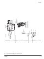
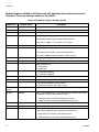
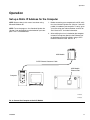
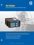
Instructions
24H372
ACS Module
3A0006D
EN
Advanced Motor Control System for Graco E-Flo® Electric Circulation Pumps. See page 4
for Required System Components. For professional use only.
Not approved for use in explosive atmospheres or hazardous locations.
Important Safety Instructions
Read all warnings and instructions in this manual
and in your E-Flo pump manuals. Save these
instructions.
ti17553a
Related Manuals
Contents
Related Manuals . . . . . . . . . . . . . . . . . . . . . . . . . . . 2
Warnings . . . . . . . . . . . . . . . . . . . . . . . . . . . . . . . . . 3
Glossary of Terms . . . . . . . . . . . . . . . . . . . . . . . . . . 3
Overview . . . . . . . . . . . . . . . . . . . . . . . . . . . . . . . . . . 4
Required System Components . . . . . . . . . . . . . . 4
Optional Components . . . . . . . . . . . . . . . . . . . . . 4
E-Flo Pump Operational Overview . . . . . . . . . . . 5
Installation . . . . . . . . . . . . . . . . . . . . . . . . . . . . . . . . 6
Inputs and Outputs . . . . . . . . . . . . . . . . . . . . . . . 6
Indicators and Pushbutton . . . . . . . . . . . . . . . . . 6
Critical Item Checklist . . . . . . . . . . . . . . . . . . . . . 7
Schematic Diagrams . . . . . . . . . . . . . . . . . . . . . . 8
Location . . . . . . . . . . . . . . . . . . . . . . . . . . . . . . 11
Mounting . . . . . . . . . . . . . . . . . . . . . . . . . . . . . . 11
Ground the ACS Control Module . . . . . . . . . . . 11
ACS Modbus Registers . . . . . . . . . . . . . . . . . . . 12
ACS Control Mode . . . . . . . . . . . . . . . . . . . . . . . . . 16
Operation . . . . . . . . . . . . . . . . . . . . . . . . . . . . . . . . 17
Set up a Static IP Address for the Computer . . . 17
ACS System Status Screen . . . . . . . . . . . . . . . . 21
Run Screen . . . . . . . . . . . . . . . . . . . . . . . . . . . . 22
Configuration Screen . . . . . . . . . . . . . . . . . . . . . 24
Alarms Screen . . . . . . . . . . . . . . . . . . . . . . . . . . 31
ACS Software Update . . . . . . . . . . . . . . . . . . . . . . 32
ACS System Setup Checklist . . . . . . . . . . . . . . . . 39
ACS Features . . . . . . . . . . . . . . . . . . . . . . . . . . . . . 40
Drive Active (System ON) Output . . . . . . . . . . . 40
Back Pressure Regulator (BPR) Production/Sleep
Modes . . . . . . . . . . . . . . . . . . . . . . . . . . . . . 40
Flow Rate Monitoring . . . . . . . . . . . . . . . . . . . . . 40
Operational Envelope Limit . . . . . . . . . . . . . . . . 40
Pressure Limits . . . . . . . . . . . . . . . . . . . . . . . . . 40
Diagnostic Procedures . . . . . . . . . . . . . . . . . . . . . 41
Technical Data . . . . . . . . . . . . . . . . . . . . . . . . . . . . 43
Dimensions . . . . . . . . . . . . . . . . . . . . . . . . . . . . . . . 43
Graco Standard Warranty . . . . . . . . . . . . . . . . . . . 44
Graco Information . . . . . . . . . . . . . . . . . . . . . . . . . 44
Related Manuals
Manual
311592
311593
311594
311603
311690
3A0539
2
Description
E-Flo Installation Manual
E-Flo Operation Manual
E-Flo Repair-Parts Manual
24J305 Sensor Circuit Option
4-Ball Lowers with open wet-cup
4-Ball Lowers with enclosed wet-cup
3A0006D
Warnings
Warnings
The following warnings are for the setup, use, grounding, maintenance, and repair of this equipment. The exclamation point symbol alerts you to a general warning and the hazard symbols refer to procedure-specific risks. When
these symbols appear in the body of this manual, refer back to these Warnings. Product-specific hazard symbols and
warnings not covered in this section may appear throughout the body of this manual where applicable.
WARNING
ELECTRIC SHOCK HAZARD
This equipment must be grounded. Improper grounding, setup, or usage of the system can cause
electric shock.
• Turn off and disconnect power at main switch before disconnecting any cables and before servicing
equipment.
• Connect only to grounded power source.
• All electrical wiring must be done by a qualified electrician and comply with all local codes and
regulations.
Glossary of Terms
Term
Description
ACS
VFD
TDC
I/O
PCB
Run
Stop
Advanced Control System
Variable Frequency Drive
Top Dead Center; measures position of pump drive
Input/output
Printed Circuit Board
Set of commands enabling motor to run in designated direction
Set of commands authorizing motor to stop running
3A0006D
3
Overview
Overview
Required System Components
Optional Components
NOTE: The following components must be installed in
every ACS system.
Optional ACS components can be ordered through your
Graco Distributor.
24J305 Sensor Circuit Kit for E-Flo Pump
(Series D and later)
15V342 Ethernet Switch
Verify that the 24J305 Sensor Circuit Kit is installed on
your E-Flo Pump. If the pump does not have the sensor
circuit, order Part No. 24J305. The kit contains the circuit board and TDC, position, and pressure sensors
necessary to utilize the Graco ACS module, taking
advantage of flow control and pressure control mode
delivered by Graco ACS software. See manual 311603.
For E-Flo Pumps Series C and earlier, check with
your local Graco Distributor for compatibility.
16D612 Power Module Assembly
Transforms AC power to a 24 Vdc power supply for the
pump sensor circuit. See manual 311608. This assembly includes the following required power supply and
barriers, which are also available separately:
121314 Power Supply (required)
24 Vdc, 2 A. DIN rail mount.
Enables connection of ACS module to multiple network
components through an Ethernet.
TI15660a
Local I/O Box
120373 (UL/CSA)
120991 (ATEX)
Allows the operator to control the E-Flo locally at the
pump when performing maintenance or troubleshooting.
See page 12. Includes the following features:
• secure disable switch
• start/stop switch
• fault reset
TI15662a
16A630 TDC and Position Sensor Barrier
(2 channel) [required]
16A633 Transducer Barrier (1 channel) [required]
TI15663a
CAT5 Ethernet Cables
121994, 1 ft (0.305 m)
121998, 25 ft (7.6 m)
121999, 50 ft (15.2 m)
15V842, 100 ft (30.5 m)
15V843, 200 ft (61.0 m)
4
3A0006D
Overview
E-Flo Pump Operational Overview
An electric motor (B) provides input to a 75:1 gear reducer (GR), which drives two fluid pumps (FP). See FIG. 1. The
stroke positions of the two pumps are offset to achieve consistent flow from the pump assembly. See FIG. 2.
The optional sensor circuit includes a top dead center (TDC) sensor to measure motor speed, a position sensor (PS)
to measure motor position, and a pressure transducer (PT) to measure fluid pressure at the pump outlet. The Graco
ACS control module software mimics the effect of a camshaft, constantly adjusting motor speed to keep steady fluid
flow and achieve minimal pressure variation. The output shaft of the gearbox and the connecting rods experience the
electrical control module simulating the function of a camshaft by speeding up when the pressure drops (pump lower
is at a changeover) and slowing down when pressure increases (both lowers are pumping).
The ACS module provides an analog drive signal to the VFD. Use one ACS module for each E-Flo pump. The ACS
module can be controlled by a local control box mounted in the hazardous area, or via communication protocol (such
as modbus).
B
GR
TDC and
Position
Sensors
(behind
cover)
PT
FP
FP
ti8317c
ti8321a
FIG. 1. Electric Circulation Pump
3A0006D
FIG. 2. Cutaway Showing Offset Stroke Positions
5
Installation
Installation
Indicators and Pushbutton
All electrical wiring must be completed by a qualified
electrician and comply with all local codes and
regulations.
FIG. 3 shows the ACS Module indicators and POWER
INTERRUPT pushbutton. See also FIG. 4 and FIG. 5.
FIG. 3 shows the ACS panel. See FIG. 4, and FIG. 5 for
schematic diagrams showing wiring connection points of
all required and optional system components.
See FIG. 6 for a detailed schematic of VFD, Barrier, and
Start/Stop connections.
Inputs and Outputs
FIG. 3 shows the ACS Module input and output terminal
block. See also FIG. 4, FIG. 5, and System Diagnostic
Indicators, page 30.
Table 1: ACS Module Indicators and Pushbutton
Indicator or
Button
Color
Condition
POWER ON
indicator
Solid
Green
The ACS is powered and
the pump is running.
DRIVE
ENABLED
indicator
Solid
Red
Turns on if the ACS is
sending an analog drive
command and the drive
enabled relay is closed.
POWER
INTERRUPT
pushbutton
n/a
Press momentarily to
interrupt power, for system reboot.
Power is restored when
released.
Indicators;
see Table
Power
Interrupt
Pushbutton;
see Table 1
FIG. 3. ACS Module Indicators and Input/Output Terminals
6
3A0006D
Installation
Critical Item Checklist
❑
Wire according to FIG. 4 on page 8 and FIG. 5 on
page 9.
❑
Use Belden 8777 cable or equivalent. It is important to use multiconductor cable with 3 individually shielded pairs.
❑
Ferrite (15D906) must be installed on pressure
transducer wires.
❑
Do not place signal wires in the same conduit as
AC Power wires. For example, the TDC/Position
sensor wires should not share a conduit with the
VFD wires.
❑
Use the following VFD configuration settings:
•
•
•
•
•
3A0006D
analog input scaling
4 mA = 0 (zero) Hz
20mA = 80 Hz
Acceleration rate = 1.0 second (for full
range 0-80 Hz)
Deceleration rate = 0.5 second (for full
range)-80 Hz)
7
FROM 16A630
9
8
8
7
FROM VFD
FROM 16A633
14
7
15
8
CONNECTION DETAILS
(22A-D8P7N104)
ALLEN BRADLEY VFD
EXAMPLE:
3 PHASE AC IN
ACS MODULE
LINE LOAD
R/L1 S/L2 T/L3 U/T1 V/T2 W/T3
ANALOG DRIVE SIGNAL
RS485 COMS / 24VDC POWER
15
6
5
4
3
2
11
02
12
03
11 +24VDC
06 DIGITAL IN 2
05 DIGITAL IN 1
04 COM
03 RUN/REV
15 4-20ma IN
16 RS485 SHLD
OUTPUT T1/T2 OR T2/T3 OR T3/T1.
ACS ANALOG VFD +
AT FAN. TO CHANGE MOTOR DIRECTION, SWAP 3 PHASE
14 ANALOG COM
15
06
13 0 - 10VDC IN
14
05
THE REQUIRED MOTOR DIRCTION IS CCW WHEN LOOKING
13
04
02 RUN/FWD
SECURE DISABLE
01 STOP INPUT/
12 +10VDC
ACS ANALOG VFD -
01
TO ACS SWITCH
TDC AND POSITION
SENSOR BARRIER
- J3 - 2 BLK
POS - BLK
+ J3 - 1 RED
POS + WHT
02 OR 03 TO RUN THE PUMP IN A SPECIFIC DIRECTION.
FROM MOTOR
CONNECTED
WIRES ARE
RESET TO +
ACS MODULE -
16
B = SLEEP MODE INPUT FROM PLC
OR FROM COMMUNICATIONS/TOUCH
SCREEN
ACS CONTROL HANDLES:
- TDC INPUT
- 4 TO 20ma PRESSURE FEEDBACK
(0 - 500 PSI)
- CALCULATES POSITION (DEG)
- DRIVE ANALOG OUT RELATIVE TO
REQUIRED SPEED PER DEGREE
PRESSURE TRANSDUCER
4-20ma BARRIER
(16A633)
4-20ma BARRIER
PRESSURE TRANSDUCER
ALARM INTERUPT OF START/STOP INPUT
THERMISTOR
ENSURE
EFLO MOTOR
WIRING DETAIL
ALLEN BRADLEY VFD
EXAMPLE:
SECURE
DISABLE
ALARM OUTPUT
(ACS RUNNING)
RESET
14
24 VDC
COMMON
13
1
6
5
TDC - J2 - 4 BLK
TDC + J2 - 3 GRN
TERMINALS 02 IS FOR STOPPING AND STARTING THE PUMP.
DISCONNECT POWER, JUST DISABLES THE VFD.)
SWITCH. (LIKE AN E-STOP BUT THIS DOES NOT
8
+
9
7
15
-
14
4
ALL SWITCHES "ON"
POSITION / POSITION I
(16A630)
13
24 VDC
3
SENSOR BARRIER
9
POS+
COMMON
2
TDC AND POSITION
8
TDC- / POS-
1
NON-HAZARDOUS
7
WIRING DETAIL
BARRIER
TDC+
2 WIRES ON
TERMINAL 8
ACS MODULE
8 CONDUCTOR CABLE
WITH SHIELD
BELDEN #9504 OR EQUIV.
TERMINALS 01 AND 04 CONNECT TO THE SECURE DISABLE
SNK POSITION
MUST BE IN
I/O SWITCH
TO MULTIPLE ACS MODULES AND
OPTIONAL EITHERNET ROUTER/SWITCH
FROM 16A630
8
WIRING DETAIL
Installation
Schematic Diagrams
FIG. 4. System Schematic Diagram, Non-Hazardous Area
3A0006D
3A0006D
PROOF CONDUIT
EXPLOSION
WIRING DETAIL
DISABLE
SECURE
RESET
START/STOP
OPERATION STATION
EXPLOSION PROOF
CONDUIT
RESET
START / STOP
SECURE / DISABLE
OPERATOR
STATION
3 PAIRS INDIVIDUALLY
SHIELDED CABLE
BELDEN 8777 OR EQUIV
WITH FERRITE (123375)
(SEE MANUAL FOR DETAILS)
WIRING DETAIL
E-FLO PUMP JUNCTION BOX
HAZARDOUS
RED
GRN
WHT
BLK
+BRN
-BLU
E-FLO
FERRITE
(16G496)
1
2
J1 3
4
5
1
2
+BRN
-BLU
PRESSURE TRANSDUCER
TDC SENSOR
POSITION SENSOR
IS CIRCUIT
E-FLO JUNCTION BOX
PRESSURE
TRANSDUCER
TDC NAMUR
SENSOR
POSITION
SENSOR
NOTE: 3 PHASE WIRING PLUS WIRING
FOR THERMISTORS ARE NOT SHOWN TO
AND FROM THE VFD/EFLO FOR CLARITY
J3
1
2
3
3
4 J2
16J588
Installation
FIG. 5. System Schematic Diagram, Hazardous Area
9
10
3A0006D
FIG. 6: Detailed Schematic, Connections to VFD
24 VDC
NON-HAZARDOUS
HAZARDOUS
3 PHASE POWER
GENERIC
VFD #1
SECURE
DISABLE
START / STOP / RESET
RESET
ANALOG DRIVE
SIGNAL
RESET
ANALOG DRIVE
SIGNAL
RESET
ANALOG DRIVE
SIGNAL
RESET
ANALOG DRIVE
SIGNAL
OPERATOR
STATION
ACS MODULE #1
PRESSURE / TDC + POS
BARRIERS #1
TDC/POS
E-FLO #1
PRESSURE
3 PHASE POWER
GENERIC
VFD #2
SECURE
DISABLE
START / STOP / RESET
OPERATOR
STATION
ACS MODULE #2
PRESSURE / TDC + POS
BARRIERS #2
TDC/POS
E-FLO #2
PRESSURE
3 PHASE POWER
GENERIC
VFD #3
SECURE
DISABLE
START / STOP / RESET
OPERATOR
STATION
ACS MODULE #3
PRESSURE / TDC + POS
BARRIERS #3
TDC/POS
E-FLO #3
PRESSURE
GENERIC
VFD #N
SECURE
DISABLE
START / STOP / RESET
OPERATOR
STATION
PRESSURE / TDC + POS
BARRIERS #N
TDC/POS
E-FLO #N
PLC CONTROL /
MONITOR
OPTIONAL ETHERNET ROUTER/SWITCH
ETHERNET COMS
3 PHASE POWER
ACS MODULE #N
PRESSURE
Installation
Installation
Location
This equipment is not for use in explosive
atmospheres. Do not install equipment approved
only for non-hazardous location in a hazardous area.
Install the ACS Module and components in a non-hazardous area.
Mounting
See Dimensions, page 43.
The ACS Module and associated components are
designed to be mounted on a DIN rail inside of the motor
control enclosure.
The ACS Module DIN rail bracket may be reversed if
desired, to accommodate installation requirements.
Remove the screws, turn the bracket 180°, and reattach.
DIN rail bracket may be
reversed if desired.
ti17553a
Ground the ACS Control Module
The equipment must be grounded. Grounding
reduces the risk of static and electric shock by
providing an escape wire for the electrical current
due to static build up or in the event of a short circuit.
Ground the ACS Module through a proper
connection to a power source.
3A0006D
11
Installation
ACS Modbus Registers
Modbus Registers 401800 to 401828 are used for ACS system control and setup.
See Table 2.
Table 2: ACS Modbus Registers 401800 to 401828
Register No.
Register Name
Description
401800
None
Not used.
401801
Model
Sets the pump model. Range of 1-4:
0 = Not used
1 = E-Flo 1500
2 = E-Flo 2000
3 = E-Flo 3000
4 = E-Flo 4000
401802
Units
0 = US GPM/PSI; 1 = Metric LPM/BAR
401803
ClrCtrFlg
Clear the Cycle Counters:
1 = Clear Batch Total.
2 = Clear Grand Total.
This register is set to 0 by the ACS when done.
401804
CamMode
1 = Cam Mode enabled. Pump is compensated to provide constant flow.
0 = Constant speed mode. Motor will run at a constant speed.
401805
Modbus Baud Rate
0 = 19,200 (Default)
1 = 38,400
2 = 57,600
Changes take effect on next power up.
401806
AutoCAMoff
Determines how the ACS responds to a TDC or Position Sensor failure.
1 = Run at constant speed determined by Run or Sleep setpoint.
0 = Stop the pump.
401807
HipressLim
High Pressure Alarm Limit x 10; ie, 2500 = 250 psi.
401808
None
Not used.
401809
AuxOn
Aux Relay ON/OFF control.
1 = ON
0 = OFF
401810
LowPressLim
Low Pressure Alarm Limit x 10; ie, 400 = 40 psi.
401811
RemoteReset
1 = Reset the ACS to clear alarms. ACS will set to 0 when Reset is complete, and the pump will start.
The Reset pin is edge triggered; a low to high will reset the ACS. Short the
Reset pin to Common, then release to reset.
12
3A0006D
Installation
Table 2: ACS Modbus Registers 401800 to 401828
Register No.
401812
Register Name
PressAlrmEnable
Description
0 = No alarms.
1 = High Pressure only.
2 = Low Pressure only.
3 = High and Low Pressure.
401813
Press_Mon
Indicates to the system that a transducer is present to read.
1 = Enable pressure transducer reads.
0 = Disable pressure transducer reads.
401814
SleepSetpt
Setpoint for Sleep Mode x 10 (GPM or LPM)
401815
RunSetpt
Setpoint for Run Mode x 10 (GPM or LPM)
401816
SleepEnable
1 = Sleep Mode is on. The Sleep Setpoint is used as the target flow rate.
0 = Sleep off. The Run Setpoint is used as the target flow rate.
Sleep can also be enable by the external AutoSleep input pin. Sleep
Mode is enabled when either control is active.
401817
PressSetPt
Pressure Mode setpoint x 10. This is the target pressure for Pressure
Control Mode.
401818
Cntrl_Mode
0 = Flow Control. Maintains a constant flow rate. Flow rate is either Sleep
or Run Setpoint, depending on 1816_SleepEnable input.
1 = Pressure Control. Maintains a constant pressure defined by
401817_PressSetPt.
401820
AutoDecrement
1 = Enabled; automatically minimizes the flow rate in pressure mode,
allowing the BPR to close. See Auto Decrement, page 27.
401821
RunStop
1 = Run
0 = Stop
Power up or Reset will set RunStop to 1.
401822
GaugePresH
High Gauge Pressure entered during calibration, PSI only
401823
GaugePresL
Low Gauge Pressure entered during calibration, PSI only
401824
ADmAHigh
High pressure CAL, Transducer current xx.x mA.
401825
ADmAHigh
Low pressure CAL, Transducer current xx.x mA.
401828
AutoXducerFail
Determines how the ACS responds to a pressure transducer failure.
1 = Run at constant flow rate determined by Run or Sleep setpoint.
0 = Stop the pump.
3A0006D
13
Installation
Modbus Registers 401900 to 401950 provide ACS operation status information and are
Read only. They must never be written to. See Table 3.
Table 3: ACS Modbus Registers 401900 to 401950
Register No.
Register Name
Description
401900
None
Not used.
401901
CalcCPM
Pump cycles per minute x 100.
401902
GT_CyclesL
Grand Total cycles low word.
401903
GT_CyclesH
Grand Total cycles high word.
To calculate the Grand Total, use the following formula:
Grand Total = (10000 * GT_CyclesH) + GT_CyclesL.
401904
Batch_CyclesL
Batch Total cycles low word.
401905
Batch_CyclesH
Batch Total cycles high word.
To calculate the Batch Total, use the following formula:
Batch Total = (10000 * Batch_CyclesH) + Batch_CyclesL.
401906
AVG_Press
Average of last 5 pressure readings.
401907
Rev
SOFTWARE VERSION.
401908
EventFlag
Modbus Display only.
7 = Start Event.
8 = Stop Event.
401909
RunningFlag
1 = The motor is rotating.
0 = The motor is stopped.
401910
AutoSlpStat
Status of the AutoSleep input. 1 = the AutoSleep input is active (low).
401911
CalcFlow
Current flow rate x 100 in GPM or LPM.
401912
XducerValidFlg
1 = Pressure transducer is valid (> 2mA).
0 = Pressure transducer has failed (< 2mA).
401913 to
401919
None
Not used.
401920
ToothStat
Status of the Position Sensor. The motor must be rotating for the system
to determine the validity of the position sensor.
1 = Valid; the ACS is receiving Position Sensor pulses.
0 = Failed; the ACS is not receiving Position Sensor pulses.
401921
PLC_ID
Modbus node number assigned to this ACS.
401922
ResetStat
Status of the ACS Reset input pin. 1 = the Reset pin is active (low).
401923
TDCStat
Status of the TDC (Top Dead Center) Sensor. The motor must be rotating
for the system to determine the validity of the TDC Sensor.
1 = Valid; the ACS is receiving TDC Sensor pulses.
0 = Failed; the ACS is not receiving TDC Sensor pulses.
14
3A0006D
Installation
Table 3: ACS Modbus Registers 401900 to 401950
Register No.
Register Name
Description
401924
HeartBeat
Alternately set to 1 and 0 every second. This indicates that the ACS program is operating.
401925
DriveCmdHz
Current drive speed command x 10; ie, 0 to 800 = 0 to 80 Hz.
401926
Current_Alarm
Represent the current alarm code.
Alarm Code No.
0 = No alarm
1 = OVERPRESS
2 = UNDERPRESS
3 = Xducer Fail
4 = NO TDC/STALL
5 = MAXFLOW
WARNING
6 = AUTO CAM
OFF-TDC
7 = START EVENT
8 = STOP EVENT
9 = AutoXducerFail
10 = MINFLOW
11 = Position Error
12 = AUTO CAM
OFF-Position
13 = AUTO CAM
ACTIVATED
Description
No current alarm/event.
System stopped due to overpressure.
System stopped due to underpressure.
Pressure Sensor failure, pump stops.
TDC failure, pump stops.
Attempted to drive > 80 Hz.
TDC Sensor failure. Pump continues to run in constant speed mode. The CAM function is disabled.
Logged only.
Logged only.
Pressure Sensor failure. Pump continues to run
without pressure monitoring.
Minimum Flow Warning, see page 30.
Position sensor failure, pump stops.
Pump continues to run in constant speed mode.
The CAM function is disabled.
CAM automatically reactivated, sensor signal
found
401927
MaxFloFlg
Set when ACS attempts to drive the motor at more than 80 Hz. Cleared
after two pump cycles.
401928
AuxOutStat
Status of the AuxOut Relay.
1 = Relay closed.
0 = Relay open.
401929
DrvEnableRlyStat
Status of the Drive Enable Relay.
1 = Relay closed.
0 = Relay open.
401930
MinFloFlg
1 = Minimum Flow Warning, see page 30.
401931
AnalogIN2
Spare Input Pins 3 and 4:
Value 0 - 4095 represents 0-20 mA current
401932 to
401946
None
Not used.
401947
ID1
‘A’ Device ID
401948
ID2
‘C’ Device ID
401949
ID3
‘S’ Device ID
3A0006D
15
ACS Control Mode
ACS Control Mode
The ACS module provides an analog drive signal to the
VFD.
120373 UL/CSA Control Box
•
Run command refers to an input command to the
VFD, requesting the motor to run in designated
direction.
•
Stop command refers to an input command
removed, requesting the motor to stop running.
SECURE
DISABLE
(wired to VFD)
The VFD drives the pump if the following conditions are
met:
START/STOP
(wired to VFD)
•
SECURE/DISABLE switch is ON
•
START/STOP switch is ON
•
There are no VFD or ACS faults
FAULT RESET
(wired to ACS)
NOTE: The local control box cannot make flow rate
changes. Use automation (PC, VB software, or process
controller) to change the flow rate.
Not Used
A control with interface must be used to select a drive
speed.
NOTE: See the schematic diagrams on pages 8-10 for
wiring details to complete the installation.
120991 ATEX Control Box
SECURE
DISABLE
(wired to
VFD)
START/STOP
(wired to VFD)
FAULT
RESET
(wired to
ACS)
Not Used
TI10719A
FIG. 7. Local Control Box
16
3A0006D
Operation
Operation
Set up a Static IP Address for the Computer
NOTE: Screen views in this manual are shown using
Microsoft Windows XP.
NOTE: To run the program, Java Version 6 Update 10+
(Version 7 not compatible) must be loaded on your computer. This is a free download.
1. Before connecting your computer to the ACS, verify
that Java Version 6 Update 10+ (Version 7 not compatible) is loaded on your computer. To verify, go to
Java.com using your Internet browser and click on
“Do I Have Java?” for further information.
2. After verifying that Java is loaded on the computer,
connect the computer directly to the Ethernet Port
on the bottom of the ACS module, using a CAT5
Ethernet crossover cable. See FIG. 8.
ACS Module
CAT5 Ethernet Crossover Cable
ACS Module
Ethernet Port
Computer
TI17645a
TI17556a
FIG. 8. Connect the Computer to the ACS Module
3A0006D
17
Operation
3. Before running the software you must manually
assign an IP address to your computer:
a. On your computer, click on the Start button
to open the menu, then click
on Control Panel
b. See FIG. 9. Double click on Network Connections. Double click on Local Area Connection to
open the Local Area Connection Status window.
Click on Properties to open the Local Area Connection Properties window. See FIG. 10.
.
FIG. 9. Control Panel, Network Connections, and Local Area Connection Status Windows
18
3A0006D
Operation
c.
In the Local Area Connection Properties window (FIG. 10), scroll to Internet Protocol
(TCP/IP) and double click, to open the Internet
Protocol (TCP/IP) Properties window (FIG. 11).
f.
Type in the following Subnet mask:
255.255.255.0
NOTE: To reconnect to the user network, change the
setting back to “Obtain an IP Address Automatically.”
g. Click on OK to accept the changes and close
the Internet Protocol (TCP/IP) Properties window.
h. Click on OK to close the Local Area Connection
Properties window.
i.
Close the Local Area Connection Status window and Network Connections window.
192 . 168 . 1 . 201
FIG. 10: Local Area Connection Properties Window
d. See FIG. 11. Set to “Use the following IP
address:”
NOTE: The IP address being created in step e
must be different from any other IP address
used in the network.
e. Type in the following 10 characters (including
the dots):
192.168.1.
then type additional numbers (for example, 201)
to create a unique IP address for the computer.
3A0006D
FIG. 11: Internet Protocol (TCP/IP) Window
19
Operation
NOTE: Verify that the wireless connection is turned off
(disabled) before performing step 4.
able field, then click
to
enter.
4. In a web browser, enter: http://192.168.1.5:9080
5. Press Enter. The ACS Module Setup Screen
appears. See FIG. 12.
6. Each ACS module is provided with a default IP
address (192.168.1.5). The assigned ACS IP
address must be different from any other IP
address in the network. Only the last digit of the
address is editable. Type a new number in the edit-
7. Set the Node ID number only if the ACS is connected to a Graco Gateway. The ID number must
be unused by other ACS modules. Click on
to access the default
Node ID number, which will then appear following
Device ID:. Type a new number in the Enter New
ID field, then click
to enter.
FIG. 12: ACS Module Setup Screen
20
3A0006D
Operation
ACS System Status Screen
See FIG. 13. The System Status screen appears when
the ACS Module is powered up. The screen displays the
current conditions and status of up to 50 pumps (numbered 0-49) in the system.
NOTE: The Visual Basic software program for the ACS
Module is available as a free download from
www.graco.com/Finishing. Navigate to the E-Flo Pump
product page for the download link.
Click on a Pump Name key to open the Run screen for
that pump. FIG. 14 shows the Run screen.
NOTE: Open the program (Start>All Programs>GracoACS>GracoACS). The program will search for all
pumps in the ACS system and populate the ACS System Status Screen. See FIG. 13.
If communication is interrupted due to a loose cable or
broken wire, first correct the problem, then click on
to re-establish communication.
NOTE: This program does not require the PC be configured with Static IP Address.
Configured through web browser, see
page 20.
Click on a Pump Name
key to open the Run
screen for that pump
(see page 23).
FIG. 13. ACS System Status Screen
3A0006D
21
Operation
Run Screen
See FIG. 14. Use the Run screen to start or stop the
pump, reset faults, access the Configuration or Alarm
screen, view setpoints, and monitor the pump’s operation by viewing performance data.
Pressure Setpoint
The Run screen displayed depends on which pump was
selected on the ACS System Status Screen, page 21.
Each Run screen applies only to the selected pump.
Fault Status
Information Bar
The Run screen information bar displays the unique
pump name, the ACS IP address, the date, and the
time.
The Pump Name is not editable on the Run screen, but
may be input on the Configuration screen. See page 24.
Pump Performance Data
Pump Speed
The pump speed is displayed in cycles per minute
(CPM).
Flow
The Pressure Setpoint is displayed, as set on the Configuration screen (see page 26).
The screen displays if there is a fault:
•
•
•
•
•
•
•
•
•
•
•
•
•
•
•
None
High Pressure
Low Pressure
Xducer (Transducer) Fail
Pressure Sensor
Auto Xducer Fail
MIN FLOW Warning
Position Error
Auto Cam Off-Position
Auto Cam Activated
No TDC Signal
Max Flow
Auto Cam Off-TDC
Start Event
Stop Event
NOTE: See page 41 for alarm descriptions and troubleshooting.
The flow is expressed in gpm or lpm, as selected on the
Configuration screen (see page 25).
Click on the Reset key to clear.
Motor Command Hz
NOTE: The pump starts after a Reset.
The speed command, in Motor VFD frequency (4-20mA
scaled 0-80 Hz). This is not the frequency output by the
VFD.
Run Button
Fluid Pressure
The fluid pressure is displayed in psi or bar, as selected
on the Configuration screen (see page 25).
Pump Setpoints
Run Setpoint
Click on the Run key to start the pump.
Stop Button
Click on the Stop key to stop the pump.
NOTE: The Run/Stop buttons function as enable/disable, active management is not necessary. This can be
left in Run and the pump/motor controlled from a physical start/stop switch connected to VFD.
The Run Setpoint is displayed, as set on the Configuration screen (see page 27).
Motor Status
Sleep Setpoint
The screen displays the status of the pump motor:
The Sleep Setpoint is displayed, as set on the Configuration screen (see page 27).
•
•
22
Stopped - ACS module receiving position pulses
Motor Running - ACS module not receiving position
pulses.
3A0006D
Operation
Config Button
Alarms Button
Click on the Config key to open the Configuration
screen. See page 24.
Click on the Alarms key to open the Alarms screen. See
page 31.
Pump Name, ACS IP Address,
Date, and Time
Pump Performance
Data
Pump Setpoints
Run
Key
Motor
Status
Display
Fault
Display
Reset Fault Key
Stop Key
Click to open
Configuration
screen (page 24).
Click to open
Alarm screen
(page 31).
FIG. 14. Run Screen
3A0006D
23
Operation
Configuration Screen
See FIG. 15. Use this screen to set the configuration for
each pump.
Transducer
Calibration
(see page 28)
System
Diagnostics
(see page 30)
Pump
Parameters
(see page 25)
System
Features
(see page 27)
Run and Sleep
Setpoints
(see page 27)
Reset Totals
(see page 29)
Alarm Settings
(see page 29)
Set the Clock
(see page 28)
Software
Levels (see
page 30)
FIG. 15. Configuration Screen
24
3A0006D
Operation
Set Pump Parameters
Measurement Units
Click on the
button to view the drop-down menu.
Select the desired units of measure:
•
•
US Units (gpm and psi)
Metric Units (lpm and bar)
NOTE: Changing the measurement units will stop the
pump.
FIG. 16. Pump Setup Fields
Select Pump Model
Click on the
button to view the drop-down menu.
Select the pump being controlled and monitored by the
ACS module. See FIG. 17. The selection activates a flow
rate setpoint range, based on the size of the pump
selected.
FIG. 18. Units Drop-down Menu
NOTE: Changing the pump model will stop the pump.
FIG. 17. Pump Model Drop-down Menu
3A0006D
25
Operation
Select Control Mode
Select Language
Click on the
button to view the drop-down menu.
Select the desired control mode:
Click on the
button to view the drop-down menu.
Select the desired language:
•
•
•
•
•
•
•
•
•
•
•
•
•
Flow (The pump will run at a constant flow rate)
Pressure (This selection turns on Cam Mode and
Pressure Transducer Enable, see page 27. The
pump will make two revolutions before entering
pressure control mode.The pump will vary
speed/flow to maintain a constant pressure.)
NOTE: The Hz command will fluctuate in pressure
mode or in flow mode if cam is enabled.
English
French
German
Chinese
Japanese
Korean
Spanish
Italian
Polish
Russian
Swedish
FIG. 19. Control Mode Drop-down Menu
Select Pressure Setpoint
Click on the
desired.
button to raise or lower the setpoint, as
Set Unique Pump Name
Input a unique name for each pump monitored by the
ACS. The name may have up to 20 characters.
FIG. 20. Language Drop-down Menu
26
3A0006D
Operation
Select System Features
Run and Sleep Setpoints
See FIG. 21.
Check the Sleep Enable box to turn on the Sleep mode.
Sleep mode will remain on until it is turned off.
Auto Decrement
Auto Decrement helps extend pump life by operating the
pump at the lowest speed necessary to maintain the
selected pressure range. Auto Decrement is operable in
pressure mode only. It reduces the flow rate incrementally by 1 Hz every 1 second until the Run Flow Setpoint
is reached while still maintaining target pressure.
Click on the
button to raise or lower the setpoints, as
desired. These values are expressed in gpm or lpm.
There are two setpoint fields:
•
Run Setpoint sets the rate of the pump when it exits
Sleep mode and enters Run mode.
•
Sleep Setpoint sets the rate of the pump during
Sleep mode.
Auxiliary Relay On
Enables peripherals such as a back pressure regulator.
Cam Mode
Enables the Cam profile. If turned off, pressure mode is
disabled.
Sensor Fault Override
Check this box to allow the pump to continue to run if
the TDC or Position sensors fail. The pump will run in
flow mode.
FIG. 22. Sleep Settings
Transducer Fault Override
Under normal operation, the ACS will shut down the
pump if the transducer fails. Selecting Transducer Fault
Override bypasses that safeguard and allows the pump
to continue to run. This selection cannot be made on
this screen; it can only be selected through Modbus.
Pressure Transducer Enable
Check this box if a pressure transducer is monitoring the
pressure. This is automatically enabled if Pressure is
selected as the Control Mode (see page 26).
FIG. 21. System Features Menu
3A0006D
27
Operation
Calibrate the Transducer
Set the Clock
NOTE: Only a 4-20 mA output transducer can be used
with the ACS.
On the Configuration screen, click on
NOTE: Calibration values for a Graco transducer are
listed on the label attached to the pump gearbox circuit
board cover. See FIG. 23. For a non-Graco transducer,
refer to the manufacturer’s label or data sheet.
(see FIG. 25). There are two methods to set the clock:
to access the clock screen
•
To input the values yourself, use the
Click on
•
buttons.
to enter.
To synchronize the ACS clock with your PC, click on
. All values will be
loaded from the PC and the window will close.
ti17606a
FIG. 23. Calibration Label Location
Enter the transducer calibration values where shown in
FIG. 24, using the
point, as desired.
button to raise or lower the set-
After the values are entered, the ACS will perform the
calibration.
FIG. 25. Set the Clock
FIG. 24. Calibration Values
28
3A0006D
Operation
Reset Totals
Alarm Enable
The screen displays the batch total and grand total
cycles for each ACS module.
There are two alarm pressure fields: Maximum Pressure
and Minimum Pressure. Check the boxes to enable the
•
alarms. Click on the
buttons to raise or lower the
pressure setpoints, as desired. These values are
expressed in psi or bar.
To reset the batch total, click on
.
FIG. 28. Alarm Settings
Click to reset batch total
FIG. 26. Reset Batch Total
•
To reset the grand total, click on
. You
will be prompted to confirm the selection.
1. Click to reset grand total.
2. Click to confirm.
FIG. 27. Reset Grand Total (GT)
3A0006D
29
Operation
System Diagnostic Indicators
See FIG. 29. The diagnostic indicators light under certain conditions, as detailed in the following paragraphs.
Motor Running
Light is on steady when the motor is running.
ACS Heartbeat
Light blinks when power is supplied to the ACS.
Maximum Flow Warning
Lights if the maximum flow setpoint exceeds the pump’s
capability.
Transducer
Lights if the system detects a pressure transducer is
present.
ACS ID#
Automatic input (Modbus node number). Not editable.
ACS Software Revision
Automatic input. Not editable.
PC Software Revision
Automatic input. Not editable.
Minimum Flow Warning
Lights if the flow rate in pressure mode is less than 80
percent of the Run Setpoint. The system reverts to flow
mode at the Run Setpoint.
The system will return to pressure mode once the pressure has dropped back below 5% of the pressure setpoint for two cycles.
Autosleep Input
Lights if a Sleep Enable input is received from the PLC.
Closes the Auxiliary Relay.
Reset Input
Lights if a Reset Fault input is received from the PLC.
TDC Sensor
Status of the TDC (Top Dead Center) Sensor. The
motor must be rotating for the system to detect the TDC
Sensor.
Position Sensor
Status of the Position Sensor. The motor must be rotating for the system to detect the Position Sensor.
NOTE: TDC and position sensor indicators will both be
lit when the motor is moving and the ACS module is
receiving proper signals.
Auxiliary Relay
Lights if Auxiliary Relay is turned on (page 27).
FIG. 29. System Diagnostic Indicators
Drive Enable Relay
Lights if Drive Enable Relay is turned on.
30
3A0006D
Operation
Alarms Screen
See FIG. 30. The Alarms screen logs the date, time, and
description of each alarm.
See page 41 for descriptions and explanations of each
alarm/warning.
Click to refresh the screen.
FIG. 30. ACS Alarms Screen
3A0006D
31
ACS Software Update
ACS Software Update
This process is required to load files to the Graco ACS
module for an upgrade of the ACS application software.
The process allows update of application software
through the Ethernet port.
It is critical that the directions be followed in the correct
order and with detail.
Required data and equipment:
•
The Graco Firmware file will be loaded through the
web browser. It will be 16J859G.CO5 (or a file of
this format with a xxx.CO5 extension of a later version). This software is available at www.graco.com.
•
Any PC/Laptop with an Ethernet port, and Mozilla
Firefox web browser program preloaded (version
3.0 or higher). Use only Mozilla Firefox. Internet
Explorer (IE) will not work properly.
1. Connect the ACS module Ethernet port to the
PC/Laptop using an Ethernet cable.
NOTE: Some laptops will allow connections with or without a crossover cable. A standard Ethernet patch cord
should work, but a crossover cable may be required
depending on how your PC/Laptop is wired.
2. Set the Static IP Address on the PC/Laptop. Ensure
the PC/Laptop network settings are configured for a
static IP Address. The PC/Laptop should be set to
the same network settings as the ACS module. The
default ACS module IP is 192.168.1.5. Therefore
set the static IP of the PC/Laptop to 192.168.1.XXX
where XXX = 200 as an example. See FIG. 31.
FIG. 31. Setting the Static IP Address on a PC or Laptop
32
3A0006D
ACS Software Update
3. When the Digital Signature Verification window
appears, click Run. Be sure that the “Always trust
content from this publisher” box is not selected. See
FIG. 32.
Click Run
Do Not Select
FIG. 32. Digital Signature Verification Window
3A0006D
33
ACS Software Update
4. Open Mozilla Firefox web browser. In the address
bar enter: http://192.168.1.5:9080. See FIG. 33.
Enter
http://192.168.1.5:9080
Use this page for configuring the
ACS module after the latest firmware upgrade to 1.02.
FIG. 33. Standard ACS Module Setup Page
5. Click the
button first. See
FIG. 34.
DO THIS FIRST
FIG. 34. Get ACS Version # Button
34
3A0006D
ACS Software Update
6. Click the
button, then the
button. The Get Device ID and
Get Device IP values must be populated on the
page before installing the new ACS software. See
FIG. 35.
GET DEVICE ID and GET DEVICE IP
values must be populated on the
page before installing the new ACS
software.
FIG. 35. Get Device ID and Get Device IP Buttons
3A0006D
35
ACS Software Update
7. Click the
button and navigate to the
16J859G.C05 (or later revision) file. Click the
button when the file link is loaded.
See FIG. 36.
Click Browse and navigate to the
16J859G.C05 (or later revision) file.
Click Program ACS when
the file link is loaded.
FIG. 36. Browse Button and Program ACS Button
36
3A0006D
ACS Software Update
8. After performing steps 6 and 7, the screen will show
window pop ups while the software is downloading
to the ACS module. See FIG. 37.
If necessary, move the window to
view the line numbers incrementing.
Line numbers will increment to 2200+
when the download is complete.
FIG. 37. Window Popup During Software Download
3A0006D
37
ACS Software Update
9. Click OK when the download is complete. The
popup window will clear automatically. See FIG. 37.
Click OK when download
is complete.
Window will clear automatically.
FIG. 38. Click OK When Download is Complete
NOTE: A new feature allows for setting of the default IP
Address of “192.168.1.5” if you cannot remember the
previous configured IP. To reset to the default IP
Address:
38
•
Power OFF the ACS Module.
•
Activate the RESET INPUT (or short to
ground/common) and HOLD.
•
Power ON the ACS Module.
•
Hold the RESET INPUT (pins 7-8 of input connector on ACS module) for 5 to 10 seconds,
then remove the RESET INPUT (with power still
applied).
•
The IP Address has now been changed to
192.168.1.5, but the change will not take affect
until power is cycled again.
•
Cycle power to the ACS Module OFF then ON,
to apply the change.
NOTE: The white power button on the ACS Module can
be used to cycle power during this process. It is not necessary to unplug the 24 Vdc supply.
3A0006D
ACS System Setup Checklist
ACS System Setup Checklist
1.
Pressure Sensor Calibration
NOTE: Only a 4-20 mA output pressure transducer can
be used with the ACS.
NOTE: Calibration values for a Graco transducer are
listed on the label attached to the pump gearbox circuit
board cover. See FIG. 23, page 28. For a non-Graco
transducer, refer to the manufacturer’s label or data
sheet.
NOTICE
Pressure sensor calibration information must be
entered into the ACS control module. Failure to do so
will result in Pressure Sensor Calibration Trip, nuisance trips, or system malfunctions.
2.
Pump Lower Size Selection
NOTE: If the pump lowers are changed to a different
size after purchase, the plate information is no longer
valid.
3.
The defaults are psi and gpm.
Table 4: Measurement Unit Summary
3A0006D
User VFD Setup
NOTE: Each VFD brand will have varying setup parameters. ACS and E-Flo performance is optimized by the
following key VFD settings:
•
analog input scaling
•
4 mA = 0 (zero) Hz
•
20 mA = 80 Hz
•
Acceleration rate = 1.0 sec (for full range 0-80 Hz)
•
Deceleration rate = 0.5 sec (for full range 0-80 Hz)
NOTE: If the ACS is used with an E-Flo 1500 pump and
a 3 HP motor, activating the VFD slip compensation feature may reduce motor heat and improve performance
under certain conditions.
5.
E-Flo Motor Specific Parameters
Verify that the parameters entered in the VFD match the
motor parameters (rated voltage, maximum rated current limit, rated frequency, rated speed in rpm).
Unit Selection
Measurement
4.
English
Metric
Pressure
psi
bar
Flow
gpm
lpm
Other setting selections will be required to allow for the
recognition of an analog speed command and motor ID
match and limits.
Contact Graco for motor information and/or a list of
locally supplied pre-approved motors.
39
ACS Features
ACS Features
Drive Active (System ON)
Output
The output can be mapped to most of the parameters.
The most common is Drive Enable. This relay output will
be closed when ACS module is running. It is used as the
Start or Run input to the VFD. It is not the Secure Disable input. See FIG. 4-FIG. 6 on pages 8-10 for further
information.
Operational Envelope Limit
Explosion-proof electric motors have constant torque
and variable torque limits. E-Flo system is a constant
torque application, and therefore the motor’s constant
torque limits must not be violated. The system is available from Graco with two motors: the UL/CSA explosion-proof motor and the ATEX explosion-proof motor.
Pressure Limits
Back Pressure Regulator (BPR)
Production/Sleep Modes
If a pressure transducer is present, set the maximum
pressure limits as shown in TABLE 6. See Alarm
Enable, page 29.
NOTE: See FIG. 4-FIG. 6 on pages 8-10 and manual
311606 for wiring and installation details.
Table 6: System Pressure Limits
Flow Rate Monitoring
Table 5: E-Flo Pump Displacement Volumes
Lower Size
40
Volume per
Cycle (cc)
Volume per
Cycle (Gal)
2000cc
4278
1.13
1500cc
3070
0.81
1000cc
2263
0.60
750 cc
1537
0.41
E-Flo
Model
Lower
Size
(cc)
E-Flo 4000
Graco Motor
Non-Graco
Motor
psi
bar
psi
bar
2000
250
17
250
17
E-Flo 3000
1500
330
23
330
23
E-Flo 2000
1000
460
32
460
32
E-Flo 1500
750
425
29
500
35
3A0006D
Diagnostic Procedures
Diagnostic Procedures
The ACS module contains two diagnostic LEDs:
•
POWER ON: Solid green when the ACS is powered
and the pump is running.
•
DRIVE ENABLED: ON (solid red) if the pump is
stopped and the drive enabled relay is open. OFF if
the pump is running and the drive enabled relay is
closed.
Table 7: Faults and Diagnostic Procedures
Fault Description
Diagnostic
High Pressure (System
pressure is higher than the
entered high pressure trip
point.)
1. Check High Pressure Alarm setting. Verify that system desired operational pressure is lower then High Pressure Alarm setting.
2. Check for flow restrictions (closed valves, unexpected restrictions).
3. Check pump fluid section for proper operation (piston seals, ball checks). Refer
to pump maintenance manual for additional information.
Low Pressure (System
pressure is lower than the
entered low pressure trip
point. This alarm is disabled for 1 minute after the
pump starts to prevent premature alarms.)
1. Check Low Pressure Alarm setting. Verify that system desired operational pressure is higher then Low Pressure Alarm setting.
Xducer Fail
Loss of pressure transducer analog signal, cause by:
2. Check fluid level. Low fluid level will cause system to run at low pressure.
3. Check fluid supply to the pump.
4. Check pump fluid section for proper operation (piston seals, ball checks). Refer
to pump maintenance manual for additional information.
•
•
•
•
Max Flow (The requested
flow rate is beyond the
pump’s capability.)
wiring problem
pressure transducer failure
circuit board failure
EMF noise on the control cable
Reduce the requested flow rate. (A 20 mA analog drive signal is the maximum.)
NOTE: This trip is a Warning and will not shut off the pump.
Min Flow (The flow rate is
too low for the Run Setpoint.)
Decrease the back pressure regulator pressure or increase the Pressure Setpoint.
Auto Cam Off (TDC/Position)
Cam mode is not functional due to loss of TDC or position sensor signal (required
for CAM operation). Verify wiring is shielded and installed correctly. See Schematic
Diagrams, page 8.
Start Event
ACS has received a start command.
Stop Event
ACS has received a stop command.
3A0006D
NOTE: This warning only occurs in pressure mode.
41
Diagnostic Procedures
Table 7: Faults and Diagnostic Procedures
Fault Description
Diagnostic
No TDC Signal (Top Dead
Center Sensor is not
detected, or motor is not
able to develop torque,
and therefore cannot put
the pump into motion)
No TDC Signal:
1. Verify that output shaft is turning.
2. Check all of the wiring.
3. Verify that sensor is operational. Remove PCB cover and monitor LED light on
the top of the sensor. The light should be normally on and it should be off for
only short period of time when top dead center is reached.
Stall:
1. Relieve system pressure.
2. Check lowers, slider cylinders, and output shaft with connecting rods for visible
damage. If no damage is visible, check for excessive heat which is a sign of friction.
3. Check the system control circuit wiring.
4. Check that the motor is turning. If not, check motor wiring.
5. Disconnect lowers and try running just the motor and gearbox.
No Position Sensor Signal (Position Sensor is not
detected, or motor is not
able to develop torque,
and therefore cannot put
the pump into motion)
No Position Sensor Signal:
1. Verify that output shaft is turning.
2. Check all of the wiring.
3. Verify that sensor is operational. Remove PCB cover and monitor LED light on
the top of the sensor. The light should be normally on and it should be off for
only short period of time when position is reached.
Stall:
1. Relieve system pressure.
2. Check lowers, slider cylinders, and output shaft with connecting rods for visible
damage. If no damage is visible, check for excessive heat which is a sign of friction.
3. Check the system control circuit wiring.
4. Check that the motor is turning. If not, check motor wiring.
5. Disconnect lowers and try running just the motor and gearbox.
42
3A0006D
Technical Data
Technical Data
Inputs
Power: . . . . . . . . . . . . . . . . . . . . . . . . . . . . . . . . . . .
Analog inputs: . . . . . . . . . . . . . . . . . . . . . . . . . . . . .
Digital inputs: . . . . . . . . . . . . . . . . . . . . . . . . . . . . . .
Outputs
4-20 mA loop:. . . . . . . . . . . . . . . . . . . . . . . . . . . . . .
Digital outputs: . . . . . . . . . . . . . . . . . . . . . . . . . . . . .
Communications . . . . . . . . . . . . . . . . . . . . . . . . . . . . .
Ambient Conditions
Operating temperature range. . . . . . . . . . . . . . . . . .
Operating humidity. . . . . . . . . . . . . . . . . . . . . . . . . .
20-30 Vdc, 200mA, reverse polarity protected
2 inputs for 4-20mA current loop sensing. Inputs protected from direct application of 24 Vdc.
4 inputs: TDC, Position Sensor, AutoSleep, and Reset.
Digital inputs are 24V logic level NPN.
2 channels, adjustable offset and span.
2 open contact, normally open relay outputs, 24V, 1A,
used for BPR control and Drive Enable.
1 Ethernet port and 1 RS485 port
0-50°C (32-121°F)
10-90% relative humidity, non-condensing
Dimensions
ACS Module
NOTE: Designed for DIN rail mounting.
C
B
A
ti17553a
3A0006D
Module
A
B
C
Weight
ACS
2.31 in.
(59 mm)
4.49 in.
(114 mm)
5.13 in.
(130 mm)
1.1 lb
(0.50 kg)
43
Graco Standard Warranty
Graco warrants all equipment referenced in this document which is manufactured by Graco and bearing its name to be free from defects in
material and workmanship on the date of sale to the original purchaser for use. With the exception of any special, extended, or limited warranty
published by Graco, Graco will, for a period of twelve months from the date of sale, repair or replace any part of the equipment determined by
Graco to be defective. This warranty applies only when the equipment is installed, operated and maintained in accordance with Graco’s written
recommendations.
This warranty does not cover, and Graco shall not be liable for general wear and tear, or any malfunction, damage or wear caused by faulty
installation, misapplication, abrasion, corrosion, inadequate or improper maintenance, negligence, accident, tampering, or substitution of
non-Graco component parts. Nor shall Graco be liable for malfunction, damage or wear caused by the incompatibility of Graco equipment with
structures, accessories, equipment or materials not supplied by Graco, or the improper design, manufacture, installation, operation or
maintenance of structures, accessories, equipment or materials not supplied by Graco.
This warranty is conditioned upon the prepaid return of the equipment claimed to be defective to an authorized Graco distributor for verification of
the claimed defect. If the claimed defect is verified, Graco will repair or replace free of charge any defective parts. The equipment will be returned
to the original purchaser transportation prepaid. If inspection of the equipment does not disclose any defect in material or workmanship, repairs
will be made at a reasonable charge, which charges may include the costs of parts, labor, and transportation.
THIS WARRANTY IS EXCLUSIVE, AND IS IN LIEU OF ANY OTHER WARRANTIES, EXPRESS OR IMPLIED, INCLUDING BUT NOT
LIMITED TO WARRANTY OF MERCHANTABILITY OR WARRANTY OF FITNESS FOR A PARTICULAR PURPOSE.
Graco’s sole obligation and buyer’s sole remedy for any breach of warranty shall be as set forth above. The buyer agrees that no other remedy
(including, but not limited to, incidental or consequential damages for lost profits, lost sales, injury to person or property, or any other incidental or
consequential loss) shall be available. Any action for breach of warranty must be brought within two (2) years of the date of sale.
GRACO MAKES NO WARRANTY, AND DISCLAIMS ALL IMPLIED WARRANTIES OF MERCHANTABILITY AND FITNESS FOR A
PARTICULAR PURPOSE, IN CONNECTION WITH ACCESSORIES, EQUIPMENT, MATERIALS OR COMPONENTS SOLD BUT NOT
MANUFACTURED BY GRACO. These items sold, but not manufactured by Graco (such as electric motors, switches, hose, etc.), are subject to
the warranty, if any, of their manufacturer. Graco will provide purchaser with reasonable assistance in making any claim for breach of these
warranties.
In no event will Graco be liable for indirect, incidental, special or consequential damages resulting from Graco supplying equipment hereunder, or
the furnishing, performance, or use of any products or other goods sold hereto, whether due to a breach of contract, breach of warranty, the
negligence of Graco, or otherwise.
FOR GRACO CANADA CUSTOMERS
The Parties acknowledge that they have required that the present document, as well as all documents, notices and legal proceedings entered into,
given or instituted pursuant hereto or relating directly or indirectly hereto, be drawn up in English. Les parties reconnaissent avoir convenu que la
rédaction du présente document sera en Anglais, ainsi que tous documents, avis et procédures judiciaires exécutés, donnés ou intentés, à la suite
de ou en rapport, directement ou indirectement, avec les procédures concernées.
Graco Information
For the latest information about Graco products, visit www.graco.com.
For patent information, see www.graco.com/patents.
TO PLACE AN ORDER, contact your Graco distributor or call to identify the nearest distributor.
Phone: 612-623-6921 or Toll Free: 1-800-328-0211 Fax: 612-378-3505
All written and visual data contained in this document reflects the latest product information available at the time of publication.
Graco reserves the right to make changes at any time without notice.
Original instructions. This manual contains English. MM 3A0006
Graco Headquarters: Minneapolis
International Offices: Belgium, China, Japan, Korea
GRACO INC. AND SUBSIDIARIES • P.O. BOX 1441 • MINNEAPOLIS MN 55440-1441 • USA
Copyright 2011, Graco Inc. All Graco manufacturing locations are registered to ISO 9001.
www.graco.com
Revision D, April 2014