1
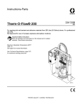
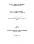
Instructions
Hotmelt/Warm Melt
Heated Hose
309160L
EN
For use with Graco temperature control systems for nonflammable hotmelt
and warm melt sealants and adhesives.
WARNING
Fire, Explosion, and Electric Shock Hazard
The operating and safety features of these hoses
are designed for use only with Graco temperature
control sysems. To reduce the risk of serious injury,
never connect these hoses to any other device.
Important Safety Instructions
Read all warnings and instructions in this manual.
Save these instructions.
PH00046
Table of Contents
List of Models . . . . . . . . . . . . . . . . . . . . . . . . . . . . . . . . . . . . . . . . . . . . 2
Symbols . . . . . . . . . . . . . . . . . . . . . . . . . . . . . . . . . . . . . . . . . . . . . . . . . 3
Warnings . . . . . . . . . . . . . . . . . . . . . . . . . . . . . . . . . . . . . . . . . . . . . . . . 3
Introduction . . . . . . . . . . . . . . . . . . . . . . . . . . . . . . . . . . . . . . . . . . . . . . 5
Installation . . . . . . . . . . . . . . . . . . . . . . . . . . . . . . . . . . . . . . . . . . . . . . . 6
Operation and Maintenance . . . . . . . . . . . . . . . . . . . . . . . . . . . . . . . . 7
Troubleshooting . . . . . . . . . . . . . . . . . . . . . . . . . . . . . . . . . . . . . . . . . 8
Technical Data . . . . . . . . . . . . . . . . . . . . . . . . . . . . . . . . . . . . . . . . . . . . 9
Graco Warranty . . . . . . . . . . . . . . . . . . . . . . . . . . . . . . . . . . . . . . . . . . 10
Graco Information . . . . . . . . . . . . . . . . . . . . . . . . . . . . . . . . . . . . . . . . 10
List of Models
2
309160
Part
No.
Length Hose Core Size
Swivel Fitting
16J875
10 ft
No. 6 (0.308” ID)
.31 ID (9/16–18 JIC(f))
120556 4 ft
No. 8 (0.401” ID)
.41 ID (3/4–16 JIC(f))
115902
6 ft
No. 8 (0.401” ID)
.41 ID (3/4–16 JIC(f))
115873
10 ft
No. 8 (0.401” ID)
.41 ID (3/4–16 JIC(f))
253281 10 ft
No. 8 (0.401” ID)
.41 ID (3/4–16 JIC(f))
115874
15 ft
No. 8 (0.401” ID)
.41 ID (3/4–16 JIC(f))
253282 15 ft
No. 8 (0.401” ID)
.41 ID (3/4–16 JIC(f))
115875
6 ft
No. 10 (0.495” ID) .51 ID (7/8–14 JIC(f))
115876
10 ft
No. 10 (0.495” ID) .51 ID (7/8–14 JIC(f))
115877
15 ft
No. 10 (0.495” ID) .51 ID (7/8–14 JIC(f))
115878
20 ft
No. 10 (0.495” ID) .51 ID (7/8–14 JIC(f))
115879
25 ft
No. 10 (0.495” ID) .51 ID (7/8–14 JIC(f))
121200 30 ft
No. 10 (0.495” ID) .51 ID (7/8–14 JIC(f))
15C586 3 ft
No. 12 (0.617” ID) .62 ID (1 1/16–12 JIC(f))
115903
6 ft
No. 12 (0.617” ID) .62 ID (1 1/16–12 JIC(f))
115880
10 ft
No. 12 (0.617” ID) .62 ID (1 1/16–12 JIC(f))
115881
15 ft
No. 12 (0.617” ID) .62 ID (1 1/16–12 JIC(f))
115882
20 ft
No. 12 (0.617” ID) .62 ID (1 1/16–12 JIC(f))
115883
25 ft
No. 12 (0.617” ID) .62 ID (1 1/16–12 JIC(f))
115884
6 ft
No. 16 (0.867” ID) .87 ID (1 5/16–12 JIC(f))
115885
10 ft
No. 16 (0.867” ID) .87 ID (1 5/16–12 JIC(f))
115886
15 ft
No. 16 (0.867” ID) .87 ID (1 5/16–12 JIC(f))
115887
20 ft
No. 16 (0.867” ID) .87 ID (1 5/16–12 JIC(f))
115888
25 ft
No. 16 (0.867” ID) .87 ID (1 5/16–12 JIC(f))
117821
10 ft
No. 20 (1.125” ID) 1.13 ID (1 5/8–12 JIC(f))
117822
15 ft
No. 20 (1.125” ID) 1.13 ID (1 5/8–12 JIC(f))
Maximum Fluid Working Pressure
@ Temperature
4000 psii (28 MPa,
MP 276 bar)
b )@
–65_F – 212_F (–54_C – 100_C)
3000 psi (21 MPa, 207 bar) @
213_F – 400_F (101_C – 204_C)
3000 psi (21 MPa, 207 bar) @
–65_F – 400_F (–54_C – 204_C)
Symbols
Warning Symbol
Caution Symbol
WARNING
CAUTION
This symbol alerts you to the possibility of serious
injury or death if you do not follow the instructions.
This symbol alerts you to the possibility of damage to
or destruction of equipment if you do not follow the
instructions.
WARNING
ELECTRIC SHOCK HAZARD
The hoses must be grounded. Improper grounding, set–up or usage of the hoses can cause electric
shock.
S
Turn off and disconnect power before installing or servicing hoses.
S
Connect to grounded power source.
S
All electrical wiring must be done by a qualified electrician and comply with all local codes and
regulations.
S
Never cut or puncture a hose cover.
S
Do not expose to rain. Store indoors.
SKIN INJECTION HAZARD
High–pressure fluid from hose leaks, or ruptured components will pierce skin. This may look like just a
cut, but it is a serious injury that can result in amputation. Get immediate surgical treatment.
S
Inspect hose before each use for cuts, bulges, kinks or any other damage.
S
Replace damaged hose immediately.
S
Replace hoses proactively at regular intervals based on your operating conditions.
S
Tighten all fluid connections before operating the equipment.
S
Keep clear of leaks.
S
Do not stop or deflect leaks with your hand, body, glove, or rag.
S
Never exceed hose Maximum Pressure or Temperature ratings.
S
Only use chemicals that are compatible with wetted parts. See Technical Data in this manual.
Read MSDSs and fluid and solvent manufacturer
S
Follow the Pressure Relief Procedure when you stop spraying/dispensing and before cleaning,
checking, or servicing equipment.
THERMAL EXPANSION HAZARD
Fluids subjected to heat in confined spaces, including hoses, can create a rapid rise in pressure due to
the thermal expansion. Over–pressurization can result in equipment rupture and serious injury.
S
Open a valve to relieve the fluid expansion during heating.
S
Replace hoses proactively at regular intervals based on your operating conditions.
BURN HAZARD
Equipment surfaces and fluid that
burns:
S
o avoid severe
Do not touch hot fluid or equipment.
309160
3
WARNING
TOXIC FLUID OR FUMES HAZARD
Toxic fluids or fumes can cause serious injury or death if splashed in the eyes or on skin, inhaled, or
swallowed.
S
Read MSDSs to know the specific hazards of the fluids you are using.
S
Store hazardous fluid in approved containers, and dispose of it according to applicable guidelines.
S
Always wear chemically impermeable gloves when spraying, dispensing, or cleaning equipment.
FIRE, EXPLOSION, AND ELECTRIC SHOCK HAZARD
Flammable fumes, such as solvent and paint fumes, in work area can ignite or explode. To help
prevent fire and explosion:
S
Use equipment only in well ventilated area.
S
Eliminate all ignition sources; such as pilot lights, cigarettes, portable electric lamps, and plastic
drop cloths (potential static arc).
S
Keep work area free of debris, including solvent, rags and gasoline.
S
Do not plug or unplug power cords, or turn power or light switches on or off when flammable fumes
are present.
S
Ground all equipment in the work area. See Grounding instructions.
S
Use only grounded hoses.
S
Hold gun firmly to side of grounded pail when triggering into pail.
S
If there is static sparking or you feel a shock, stop operation immediately. Do not use equipment
until you identify and correct the problem.
S
Keep a working fire extinguisher in the work area.
EQUIPMENT MISUSE HAZARD
Misuse can cause death or serious injury.
S
Do not operate the unit when fatigued or under the influence of drugs or alcohol.
S
Do not exceed the maximum working pressure or temperature rating of the lowest rated system
component. See Technical Data in all equipment manuals.
S
Use fluids and solvents that are compatible with equipment wetted parts. See Technical Data in all
equipment manuals. Read fluid and solvent manufacturer
about your material, request MSDS from distributor or retailer.
S
Do not leave the work area while equipment is energized or under pressure. Turn off all equipment
and follow the Pressure Relief Procedure when equipment is not in use.
S
Check equipment daily. Repair or replace worn or damaged parts immediately with genuine
manufacturer
.
S
Do not alter or modify equipment.
S
Use equipment only for its intended purpose. Call your distributor for information.
S
Route hoses and cables away from traffic areas, sharp edges, moving parts, and hot surfaces.
S
Do not kink or over bend hoses or use hoses to pull equipment.
S
Keep children and animals away from work area.
S
Comply with all applicable safety regulations.
PERSONAL PROTECTIVE EQUIPMENT
You must wear appropriate protective equipment when operating, servicing, or when in the operating
area of the equipment to help protect you from serious injury, including eye injury, hearing loss, inhalation of toxic fumes, and burns. This equipment includes but is not limited to:
4
S
Protective eyewear, and hearing protection
S
Respirators, protective clothing, and gloves as recommended by the fluid and solvent
manufacturer.
309160
Introduction
Each hose assembly must be controlled by a Graco
zone controller. The amount of hose used depends on
the zone controllers available for control.
The hose has two electrical connectors with cables,
each extending from the end of the hose.
The large rectangular connector is the machine end
and has 8 foot (2.42 m) of cable (see Fig. 1). The
small square connector is the gun end and has 2 foot
(0.6 m) of cable (see Fig. 2).
PH00051
Fig. 2
Connect the machine end connector to the Graco
temperature controller by pushing the connector on the
mating receptacle of the temperature controller or
accessory device and securing the latch.
Fig. 1
Connect the gun end connector to any temperature
controller accessory device. These include Graco
manual and automatic hot melt dispense valves,
pressure compensators, manifolds, headers, and
pressure regulators.
309160
5
Installation
WARNING
4. Do not flex hose when cold.
THERMAL EXPANSION HAZARD
Fluids subjected to heat in confined
spaces, including hoses, and create a
rapid rise in pressure due to the thermal
expansion. Over–pressurization can
result in equipment rupture and serious injury.
S
S
Open a valve to relieve the fluid expansion
during heating.
Replace hoses proactively at regular intervals
based on your operating conditions.
5. Use hose support spring.
WARNING
SKIN INJECTION HAZARD
To reduce the risk of serious injury,
follow the Pressure Relief Procedure
on page 7 whenever you are instructed
to relieve pressure.
NOTE: Pressure check the hose assemblies. Refer to
your system operation manual for priming and pressurizing the fluid hoses. Check carefully for leaks at the
hose connections. If there are leaks, relieve the pressure as instructed on page 7.
1. Do not use hose to pull the equipment.
6. Do not clamp, squeeze, or zip tie hose.
7. Minimum bend radius:.
Fitting Radius
–4
8 in. (203 mm)
–6
8 (203)
–8
10 (254)
–10
12 (305)
–12
14 (356)
–16
18 (457)
–20
22 (559)
–24
26 (660)
8. Do not bend or crimp hose.
2. Use 2 wrenches to tighten. Torque to specification:
Fitting
–4
–6
–8
–10
–12
–16
–20
–24
Torque,
in–lb ( NSm)
150 (16.9)
300 (33.9)
500 (56.5)
700 (79.1)
1000 (113.0)
1400 (158.2)
2100 (237.3)
3000 (339.0)
3. Do not tape or cover hose.
6
309160
9. Do not twist hose.
10. Use proper length hose.
Operation and Maintenance
Pressure Relief Procedure
Operation
WARNING
WARNING
SKIN INJECTION HAZARD
The system pressure must be manually
relieved to prevent the system from
starting or dispensing accidentally. Fluid
under high pressure can be injected through the
skin and cause serious injury. To reduce the risk of
an injury from injection, splashing fluid, or moving
parts, follow the Pressure Relief Procedure
whenever you:
S
S
S
S
are instructed to relieve the pressure,
stop dispensing,
check or service any of the system equipment,
or install a new or clean the dispense gun
tip/nozzle.
This equipment should not be used with
more than one type of fluid due to potential compatibility issues which could
result in an unpredictable reaction.
Graco recommends using new hoses
when chemicals are changed or care
must be taken to assure that all traces of one
chemical are removed before introducing a second
chemical.
CAUTION
S
Do not pressurize hose until operating temperature has been reached.
S
Operate at lowest possible temperature and
pressure necessary for application.
1. Lock the gun trigger safety.
S
Hose must be vented during startup and shutdown.
2. Shut off the air to the supply pumps.
S
The dispense valve must be kept open over a
waste container while the system is heating up
and also when cooling down. This will prevent a
pressure build–up caused by fluids or gasses
expanding from the heat.
3. Turn off the power (air) to the proportioning pump.
4. Unlock the spray gun trigger safety.
Refer to your system operation manual for complete
startup and operating instructions.
5. Hold a metal part of the gun firmly to the side of a
grounded metal pail, then trigger the gun to relieve
pressure.
Maintenance
6. Lock the trigger safety again.
7. If you suspect that the dispense valve or hose is
completely clogged, or that pressure has not been
fully relieved after following the steps above, very
slowly loosen the tip retaining nut or hose end
coupling to relieve pressure gradually, then loosen
completely. Wear protective gloves to avoid skin
injection or burns. Now clear the tip/nozzle or
hose.
WARNING
SKIN INJECTION HAZARD
Do not mend or repair any part of a hose
assembly. If the hose is damaged,
replace it immediately to avoid serious
injury from fluid injection and electric shock.
If the hose is not heating, be sure the connector at the
hose control box is firmly plugged in. If that does not
correct the problem, relieve the fluid pressure in the
pump and hoses, as instructed at left. If the hose is
faulty or the problem not corrected, replace the hose.
See Troubleshooting on page 8 for electrical measurements.
8. Be sure the fluid is cool before disconnecting the
hoses.
309160
7
Troubleshooting
9. Check the continuity of the hose components.
a. Use an ohmmeter to check the electrical
resistance at the heating element pins between pins A1 and A2 of the machine end
connector (A) that attaches to the heated hose
control. See Fig.1. The resistance of the
heating element for the various lengths of
coupled hose assemblies is given in the following coupled hose chart.
Length/ft
Pins A1 & A2
Resistance Values (ohms) at 230 VAC
Temperature
Pins A4 & A5
Approximate Resistance Values
(ohms)
C
F
16
60
106
27
80
110
38
100
115
49
120
119
60
140
123
71
160
128
82
180
132
6
176
+/– 18
93
200
136
10
106
+/– 11
104
220
140
15
71
+/– 7
116
240
144
20
53
+/– 5
127
260
149
25
42
+/– 4
138
280
153
149
300
160
160
320
161
171
340
165
182
360
170
193
380
174
204
400
177
Any resistance reading outside the range may indicate
a faulty hose
The resistance values of the RTD will vary with temperature. An approximation of hose temperature must
be made to verify the resistance reading of the RTD
across pin A4 and A5 is correct.
b. Between pin A4 and A5 of the large machine
end connector, the RTD resistance must be
within the range of the following chart.
8
Approximate RTD resistance values at various temperatures.
309160
10. Check all hose connections to be sure they are
securely tightened.
11. Ground the system.
Troubleshooting
Make sure there is electrical continuity (<10Ω) between the following pins of the large machine end
connector and the small gun end connector
Lack of electrical continuity between any of these pins
is a failure of the hose. Replace the hose assembly.
Continuity Between Connectors
Machine End
Gun End
B1
1
B2
2
B3
5
B4
3
B5
4
C1
6
C2
7
GND
GND
Fig. 3
Technical Data
Maximum fluid working pressure . . . . . . . . . . . . . . . . . . . . See table on page 2
Maximum working temperature . . . . . . . . . . . . . . . . . . . . . See table on page 2
Hose fluid fittings . . . . . . . . . . . . . . . . . . . . . . . . . . . . . . . . . See table on page 2
Power required . . . . . . . . . . . . . . . . . . . . . . . . . . . . . . . . . . . 230 VAC, 50/60 Hz
Wetted parts . . . . . . . . . . . . . . . . . . . . . . . . . . . . . . . . . . . . . PTFE core, SST couplings
Power consumption . . . . . . . . . . . . . . . . . . . . . . . . . . . . . . . 50 3 watts/linear foot of hose
(164 10 watts/linear meter of hose)
Minimum Bend Radius . . . . . . . . . . . . . . . . . . . . . . . . . . . . Hose with No. 6 – No. 16 core = 8 in. (20 cm)
Hose with No. 20 core = 12 in. (30 cm)
309160
9
Graco Standard Warranty
Graco warrants all equipment manufactured by Graco and bearing its name to be free from defects in material and workmanship on the
date of sale to the original purchaser for use. With the exception of any special, extended, or limited warranty published by Graco,
Graco will, for a period of twelve months from the date of sale, repair or replace any part of the equipment determined by Graco to be
defective. This warranty applies only when the equipment is installed, operated and maintained in accordance with Graco’s written
recommendations.
This warranty does not cover, and Graco shall not be liable for general wear and tear, or any malfunction, damage or wear caused by
faulty installation, misapplication, abrasion, corrosion, inadequate or improper maintenance, negligence, accident, tampering, or substitution of non–Graco component parts. Nor shall Graco be liable for malfunction, damage or wear caused by the incompatibility of
Graco equipment with structures, accessories, equipment or materials not supplied by Graco, or the improper design, manufacture,
installation, operation or maintenance of structures, accessories, equipment or materials not supplied by Graco.
This warranty is conditioned upon the prepaid return of the equipment claimed to be defective to an authorized Graco distributor for
verification of the claimed defect. If the claimed defect is verified, Graco will repair or replace free of charge any defective parts. The
equipment will be returned to the original purchaser transportation prepaid. If inspection of the equipment does not disclose any defect
in material or workmanship, repairs will be made at a reasonable charge, which charges may include the costs of parts, labor, and
transportation.
THIS WARRANTY IS EXCLUSIVE, AND IS IN LIEU OF ANY OTHER WARRANTIES, EXPRESS OR IMPLIED, INCLUDING BUT
NOT LIMITED TO WARRANTY OF MERCHANTABILITY OR WARRANTY OF FITNESS FOR A PARTICULAR PURPOSE.
Graco’s sole obligation and buyer’s sole remedy for any breach of warranty shall be as set forth above. The buyer agrees that no other
remedy (including, but not limited to, incidental or consequential damages for lost profits, lost sales, injury to person or property, or any
other incidental or consequential loss) shall be available. Any action for breach of warranty must be brought within two (2) years of the
date of sale.
Graco makes no warranty, and disclaims all implied warranties of merchantability and fitness for a particular purpose in connection
with accessories, equipment, materials or components sold but not manufactured by Graco. These items sold, but not manufactured
by Graco (such as electric motors, switches, hose, etc.), are subject to the warranty, if any, of their manufacturer. Graco will provide
purchaser with reasonable assistance in making any claim for breach of these warranties.
In no event will Graco be liable for indirect, incidental, special or consequential damages resulting from Graco supplying equipment
hereunder, or the furnishing, performance, or use of any products or other goods sold hereto, whether due to a breach of contract,
breach of warranty, the negligence of Graco, or otherwise.
FOR GRACO CANADA CUSTOMERS
The parties acknowledge that they have required that the present document, as well as all documents, notices and legal proceedings
entered into, given or instituted pursuant hereto or relating directly or indirectly hereto, be drawn up in English. Les parties reconnaissent avoir convenu que la rédaction du présente document sera en Anglais, ainsi que tous documents, avis et procédures judiciaires
exécutés, donnés ou intentés à la suite de ou en rapport, directement ou indirectement, avec les procedures concernées.
Graco Information
For the latest information about Graco products, visit www.graco.com.
TO PLACE AN ORDER, contact your Graco distributor or call to identify the distributor closest to you:
Phone: 612–623–6921 or Toll Free: 1–800–328–0211 Fax: 612–378–3505
All written and visual data contained in this document reflects the latest product information available at the time of publication.
Graco reserves the right to make changes at any time without notice.
For patent information, see www.graco.com/patents.
Original instructions. This manual contains English. MM 309160
Graco Headquarters: Minneapolis
International Offices: Belgium, China, Japan, Korea
GRACO INC. AND SUBSIDIARIES S P.O. BOX 1441 S MINNEAPOLIS MN 55440–1441 S USA
Copyright 2000, Graco Inc. All Graco manufacturing locations are registered to ISO 9001.
www.graco.com
Revised December 2012
10
309160