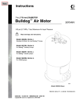
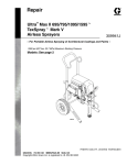
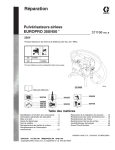
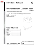
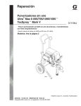
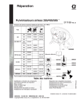
1
Instructions – Parts List
CycleFlo™ Pneumatic
Pump Controller
309003E
ENG
Controls pump speed, run time, and quantity of product delivered, for precise
batching, metering, and dosing of fluids at high or low pressures and flow rates.
Not for use in explosive atmospheres.
Part No. 195264 (120 VAC)
Part No. 196706 (240 VAC)
120 psi (0.8 MPa, 8 bar) Maximum Air Inlet Pressure
D Integrated Air Valves with Silenced Exhaust
D 32 Batch Presets
D 1–999 Pump Cycles per Batch Preset
D x10 Cycle Multiplier for High Volume Applications (10–9990 Cycles)
D 16 Pump Cycle Rates (10–200 CPM)
D Easy Field Programming
D Self-Test Function for Easy Troubleshooting
D Standard 120 or 240 VAC Power
Important Safety Instructions
Read all warnings and instructions in this
manual. Save these instructions.
9408B
Table of Contents
Symbols . . . . . . . . . . . . . . . . . . . . . . . . . . . . . . . . . . . . . .
Warnings . . . . . . . . . . . . . . . . . . . . . . . . . . . . . . . . . . . . . .
General Description . . . . . . . . . . . . . . . . . . . . . . . . . . . .
Installation . . . . . . . . . . . . . . . . . . . . . . . . . . . . . . . . . . . . .
Pneumatic Connections . . . . . . . . . . . . . . . . . . . . . . .
Electrical Connections . . . . . . . . . . . . . . . . . . . . . . . .
Setup and Programming . . . . . . . . . . . . . . . . . . . . . . . .
Cycles Per Minute (CPM) Rate . . . . . . . . . . . . . . . . .
Presets . . . . . . . . . . . . . . . . . . . . . . . . . . . . . . . . . . . . .
Operation . . . . . . . . . . . . . . . . . . . . . . . . . . . . . . . . . . . . .
2
309003
3
3
5
6
6
6
8
8
8
9
Priming the Pump . . . . . . . . . . . . . . . . . . . . . . . . . . . . 9
Front Panel Operation . . . . . . . . . . . . . . . . . . . . . . . . 9
Remote Operation . . . . . . . . . . . . . . . . . . . . . . . . . . . . 9
Troubleshooting . . . . . . . . . . . . . . . . . . . . . . . . . . . . . . . 10
Self-Test Mode . . . . . . . . . . . . . . . . . . . . . . . . . . . . . . . . 11
Parts . . . . . . . . . . . . . . . . . . . . . . . . . . . . . . . . . . . . . . . . 12
Typical Installation Diagrams . . . . . . . . . . . . . . . . . . . . 13
Specifications . . . . . . . . . . . . . . . . . . . . . . . . . . . . . . . . . 17
Mounting Information . . . . . . . . . . . . . . . . . . . . . . . . . . 17
Graco Standard Warranty . . . . . . . . . . . . . . . . . . . . . . 18
Graco Information . . . . . . . . . . . . . . . . . . . . . . . . . . . . . 18
Symbols
Warning Symbol
Caution Symbol
WARNING
CAUTION
This symbol alerts you to the possibility of serious
injury or death if you do not follow the corresponding
instructions.
This symbol alerts you to the possibility of damage to
or destruction of equipment if you do not follow the
corresponding instructions.
WARNING
EQUIPMENT MISUSE HAZARD
Equipment misuse can cause the equipment to rupture or malfunction and result in serious injury.
INSTRUCTIONS
D This equipment is for professional use only.
D Read all instruction manuals, warnings, tags, and labels before operating the equipment.
D Use equipment only for its intended purpose. If you are uncertain about usage, call your Graco
distributor.
D Other than for installation purposes, do not alter or modify this equipment. Use only genuine
Graco parts and accessories.
D Check equipment daily. Repair or replace worn or damaged parts immediately.
D Do not exceed the maximum working pressure of the lowest rated system component.
D Route hoses away from traffic areas, sharp edges, moving parts, and hot surfaces. Do not
expose Graco hoses to temperatures above 82° C (180° F) or below -40° C (-40° F).
D Do not lift pressurized equipment.
D Comply with all applicable local, state and national fire, electrical, and other safety regulations.
309003
3
WARNING
FIRE, EXPLOSION, AND ELECTRIC SHOCK HAZARD
Improper grounding, poor air ventilation, open flames, or sparks can cause a hazardous condition
and result in fire or explosion and other serious injury.
D Ground the pumping equipment. Proper grounding dissipates static electricity.
D This equipment is not intended for intrinsically safe areas.
D Keep the dispense area free of debris, including solvent, rags, and gasoline.
D If there is any static sparking or you feel an electric shock while using the equipment, stop operating immediately. Do not use the equipment until you have identified and corrected the
problem.
D Make sure all electrical work is performed by a qualified electrician.
D Have any checks, installation, or service to electrical equipment performed by a qualified electrician only.
D Make sure all electrical equipment is installed and operated in compliance with local and applicable codes.
D Make sure power is disconnected when servicing and repairing equipment.
D Keep liquids away from the electrical components.
D Disconnect electrical power at the main switch before servicing equipment.
D Never exceed maximum wattage of the supply unit.
4
309003
General Description
The CycleFlo is a pneumatic pump controller that
allows precise control over the amount of product that
is delivered by the pump, as well as the pump speed.
The CycleFlo achieves this by operating the pump for
a preset number of cycles and then halting the pumping cycle. Up to 32 different batch sizes may be programmed into the memory of the CycleFlo for easy
delivery of different product volumes.
The CycleFlo also features an adjustable pumping
rate. This allows the CycleFlo to be used with different
pump types and also to tailor the pump cycle to deliver
fluids with a variety of flow characteristics.
A batch may be initiated either from the front panel
RUN button or via a remote switch. Such a remote
switch may be connected to the trigger of a dispensing
valve so that the pump only pumps when the operator
depresses the valve trigger. Using the remote input,
the pumping cycle may also be initiated by some other
piece of equipment such as a timer or a pH controller.
The CycleFlo will halt the pumping cycle once the
preset volume of product has been dispensed.
309003
5
Installation
Pneumatic Connections
The integrated air valves (solenoids #1 and #2), located on the right side of the CycleFlo enclosure, have
a common air inlet (1/4 in. npt) port at the bottom and
two outlet ports (1/8 in. npt to 1/4 in. elbow tube fitting)
towards the front of the unit. The exhaust is silenced
with a muffler.
An access hole with a strain relief installed has been
provided for the external power connection. Due to the
unique requirements of each installation, access holes
have not been provided for other optional external
wiring connections. Access holes will need to be added
for the external Air Supply Valve Signal and/or Remote
Run options. Have a qualified electrician determine the
proper strain relief, wire type, and wire size for your
particular application. When positioning or adding
access holes, be careful not to damage any internal
components. Failure to use the proper strain relief,
wire type, and wire size can cause damage to internal
components or personal injury.
The 24 Volt DC Air Supply Valve Signal output is used
to control a three-way valve (Graco Part No. 115605 or
equivalent) on the main air supply of pumps larger than
the Husky 205. This ensures that pressure is not
generated by the pump when the controller is not
operating. Failure to use this valve can cause damage
to the unit and possible personal injury.
Fig. 1
The A and B outlet ports are to be connected to the A
and B ports, respectively, on the Huskyt 205, or to
the two air valve control ports located on the air motors
of pumps larger than the Husky 205. The unit comes
equipped with 1/4 in. OD push-in tube fittings installed
in the A and B ports.
On pumps larger than the Husky 205, a three-way
solenoid valve (Graco Part No. 115605 or equivalent)
should be installed on the main air supply to the pump.
This ensures that pressure is not generated by the
pump when the controller is not operating. The air
supply valve signal output on the CycleFlo controller is
designed to control this valve.
WARNING
Failure to use the recommended valve can cause
damage to the unit and possible personal injury.
Follow the pressure relief procedure in the pump
manual before moving or servicing the pump.
The CycleFlo requires 120/240 VAC, 50/60 Hz to
operate. The power input is fuse-protected with a 160
mA fuse for 120 Volt service and an 80 mA fuse for
240 Volt service (see Fig. 2).
Electrical Connections
WARNING
FIRE, EXPLOSION, AND ELECTRIC
SHOCK HAZARD
To reduce the risk of fire, explosion, or
electric shock:
D The power source conduit is not an
adequate ground for the system. The
unit must be grounded to a true earth
ground.
D A qualified electrician must complete
all grounding and wiring connections
and check the resistance.
D Refer to your local code for the requirements for
a “true earth ground” in your area.
6
309003
WARNING
When replacing the fuse, make sure to replace it
only with one of equivalent rating. Failure to do so
may cause damage to the unit and possible personal injury.
Connect power to the unit as described. Always have a
qualified electrician perform wiring connections. Connect Line (L) and Neutral (N) wires to the terminal
block as shown in Fig. 2. The Ground wire (GND) must
be attached to the #10–32 ground stud. A crimp-on
ground wire lug comes attached to the ground stud.
Remove the lug and attach to the ground wire. Replace the lug assembly back onto the stud and fasten
down with the kepsnut provided.
Installation
1
2
3
4
CPM Rate
5 x10 CPM Multiplier
6 Program Mode
7 Test Mode
8 Remote Run Test
26
25
24 VDC, 6W max.
–
SW1
DIp Switch
24 VDC, 6W max.
24 VDC, 6W max.
24 VDC, 6W max.
1
2
+
+
–
Remote Run
Input
Air Supply
Valve Signal
Output
+
–
Solenoid
Valve #1
+
Solenoid
Valve #2
–
Micro Processor
160 Fuse
mA or 80 mA
Transformer
J2 J1
Terminal
Block
L
N
J3
Power
L
N
(120 VAC
or
GRND
240 VAC)
Fig. 2
The Remote Run input is an external switch input. A
switch connected to this input should be a potential
free contact.
The Air Supply Line Valve Signal is a 24 VDC output
signal. This signal drives the external 6W solenoid
valve (Graco Part No. 115605), which controls the
main air supply (required for pumps larger than the
Husky 205).
Solenoid Valve #1 and #2 Signals (24 VDC output
signals) are pre-connected to the air valves on the
right side of the CycleFlo.
Power Connections
Connect Line (L), Neutral (N), and Ground (GND) as
shown in Fig. 2. Ground wire must be attached to the
ground stud and fastened down with the nut provided.
309003
7
Setup and Programming
An 8-position DIP switch (SW1) (see Fig. 1 for location) is used to set the cycle rate and cycles multiplier.
It is also used to invoke the various test modes.
Before the CycleFlo can be put into operation, the
parameters in Fig. 3 must be programmed for each
particular application.
OFF
ON
1
2
3
CPM Rate
See Fig. 4
4
5 x10 Cycles Multiplier
6 Program Mode
7 Test Mode
8 Remote Run Test
Presets
The CycleFlo has 32 programmable presets to easily
switch between amounts of fluid delivered by the pump
during a RUN cycle. Each preset is programmed with
the number of times the pump will be cycled. Use the
Y and B buttons on the front panel to step through
the presets. The PRESET display will indicate the
selected PRESET program number and the CYCLES
display will show the associated number of pump
cycles.
NOTE: SW1–5 is the x10 Cycle Multiplier. If SW1–5 is
in the ON position, the actual number of pump cycles
will be 10 times that of the CYCLES display.
To change the number of cycles associated with a
programmed preset, do the following:
1. Place the CycleFlo into Program Mode by moving
SW1–6 to ON. The PRESET display will blink to
indicate that the Program Mode is active.
SW1
Fig. 3
2. Use the BY buttons to select the PRESET to be
changed.
Cycles Per Minute (CPM) Rate
The pump cycle rate is adjustable to accommodate
different pump sizes, varying product viscosity, and
product delivery speed. The pump cycle rate is measured in cycles per minute (CPM), which is the number
of times the pump performs a pump cycle in one
minute. One pump cycle consists of a momentary
pressurization of each one of the two diaphragms.
The CPM Rate Table in Fig. 4 shows the settings for
the first four switches of SW1 and the resulting CPM
rate.
CPM
10
15
20
25
30
35
40
45
50
62
75
88
100
125
150
200
SW1 CPM Rate Table
4. Press and hold the RESET button, then use the B
and Y buttons to adjust the 10’s digit of the
CYCLES display.
5. Press and hold the PRIME button, then use the B
and Y buttons to adjust the 1’s digit of the
CYCLES display.
6. Once the correct number of cycles is displayed,
use the B and Y buttons to move to another
PRESET and then back to the current one to verify
that the new cycle count was stored correctly.
NOTE: Either the B or Y button must be pressed for
the new cycle count to be programmed into the CycleFlo’s memory.
1
2
3
4
7. Repeat for the next PRESET, as needed.
Denotes Switch is ON
Fig. 4
8
3. Press and hold the RUN button, then use the B
and Y buttons to adjust the 100’s digit of the
CYCLES display.
309003
8. When finished, switch SW1–6 to the OFF position
to place the CycleFlo into Normal Operating mode.
Operation
Priming the Pump
A priming feature allows for the temporary operation of
the pump for priming purposes. The pump cycle rate
during priming is controlled by the 8-position DIP
switch (SW1).
Pressing the PRIME button on the front panel will start
the pump cycling while the button is held. Once
primed, release the button to stop pump operation.
Front Panel Operation
The B and Y buttons (see Fig. 5) select the desired
PRESET pump cycle. The pump cycle count for each
PRESET is displayed in the CYCLES display.
Pressing the RUN button on the front panel starts the
pump cycling for the number of cycles indicated by the
CYCLES display. The CYCLES display will count down
from its current count every time the pump performs a
complete cycle (both diaphragms alternately activated). When all cycles have been performed, the
pump will stop and the CYCLES display will automatically be reset to the full cycle count for the current
PRESET. The unit is then ready for another dispense
cycle.
Pressing the RESET button during a RUN operation
stops the pumping cycle. The CYCLES display will
blink to indicate that the RUN mode was interrupted.
Once in this mode, there are two possible actions:
pressing the RUN button will resume the pump cycling
where it was interrupted or pressing the RESET button
again will reset the CYCLES to the full count for the
current PRESET.
Remote Operation
B Decrease
The B and Y buttons select the desired PRESET
number of pump cycles. Pump cycles for each PRESET are displayed in the CYCLES display.
Y Increase
Cycles
Preset
Opening the REMOTE RUN contact stops the pump
cycling. The CYCLES display will blink to indicate that
the RUN mode was interrupted. Once in this mode,
there are two possible actions: closing the REMOTE
RUN contact again will resume the pump cycling
where it was interrupted or pressing the RESET button
on the front panel will reset the CYCLES to the full
count for the current PRESET.
Run
Emergency Stop
Fig. 5
Closing the REMOTE RUN contact starts the pump
cycling for the number of cycles indicated by the
CYCLES display. The CYCLES display will count down
from its current count every time the pump performs a
complete cycle (both the diaphragms alternately activated). When all cycles have been performed, the
pump will stop and the CYCLES display will automatically be reset to the full cycle count for the current
RESET.
Prime
Reset
9408B
When all cycles have been performed, the pump will
stop and the CYCLES display will show 000 until the
REMOTE RUN contact is opened. The CYCLES
display will then automatically be reset to the full cycle
count for the current PRESET.
309003
9
Troubleshooting
The following is a list of possible problems and their causes. The CycleFlo also has a built-in self-test mode that
allows dynamic testing of all components.
Troubleshooting Guide
Problem
No operation at all
LED display shows incomplete
digits
Front panel button(s) don’t work
Pump won’t operate when RUN
button is pressed
p
Cause
Solution
Blown fuse.
Check fuse and replace with 250 V
1/4A type.
Emergency Stop switch OFF.
Press switch.
Poor ribbon cable connection.
Turn power off and unplug then replug ribbon cable on main board and
display board.
Damaged display board.
Replace board.
Poor ribbon cable connection.
Turn power off and unplug then replug ribbon cable on main board and
display board.
Loose mounting screw.
Make sure mounting screws on display board are securely tightened.
Damaged display board.
Replace board.
Incorrect operating mode.
Make sure SW1–6, 7, 8 are all in the
OFF position.
No or low air supply.
Check air supply to make sure there
is sufficient pressure and air available.
Pump won’t operate (cycles count Bad solenoid wire connections.
down and valve driver LED’s
blink)
Pump won’t operate (CYCLES
count down but no valve driver
LED’s)
10
309003
Turn off power and check wire connections from solenoid valve #1 and
#2 to make sure they are all connected and seated properly.
Bad solenoid valve(s).
Turn off air supply and listen for
“clicking” on solenoid valves; replace
valves if no “clicking” is audible.
Bad valve drivers on main board.
Replace main board.
Self-Test Mode
CAUTION
During this test, the solenoid valves may be activated. This will activate a connected pump. To
prevent inadvertent pumping, disconnect the air
supply to the solenoid valves or remove the air lines
to the pump.
D Each of the five front panel buttons activates a
decimal point on the LED displays. Replace the
display board if a button fails to activate a decimal
point.
Position SW1–7 to the ON position to activate the
self-test mode. Position SW1–7 to the OFF position to
de-activate the self-test mode.
TEST MODE (SW1–7)
The CycleFlo has a built-in test program that allows for
dynamic testing of all internal and external components.
Once activated, the self-test mode will do the following
continuously until the test mode is de-activated:
D All display digits count from 0–9 in unison. This is
used to determine if any of the displays are faulty.
Replace the display board if segments of the display fail to activate during the self-test.
REMOTE RUN TEST (SW1–8)
Position SW1–8 (the REMOTE RUN test) to the ON
position to activate the AIR SUPPLY VALVE signal and
cycle the solenoid valves at the CPM rate set by
SW1–1, 2, 3, 4. The Remote Run Test (SW1–8) performs the same function as closing the Remote Run
Switch input, and therefore, is used to test the functionality of the Remote Run Switch input. Follow the
Troubleshooting Guide on page 10 if either fails to
operate.
309003
11
Parts
Ribbon Cable
Main Board
Display
Board
Air
Valve
Enclosure
Parts
Part No.
Description
195264
CycleFlo Pneumatic Pump Controller Unit (120 VAC)
196706
CycleFlo Pneumatic Pump Controller Unit (240 VAC)
–––––
Enclosure
–––––
Emblem (not shown – located on front of unit) (120 VAC)
–––––
Emblem (not shown – located on front of unit) (240 VAC)
115381
Main Board (120 VAC)
116111
Main Board (240 VAC)
115380
Display Board
115382
Ribbon Cable
115383
Air Valve (NOTE: two valves are required per controller)
Part No.
Optional Accessories
Description
102518
Cord Set, Electrical
115988
Tube, Nylon, 50 ft
115605
Valve, Solenoid, 24 VDC, 6W
––––– Not sold separately.
12
309003
Typical Installation Diagrams
120 or 240 VAC
CycleFlo
Controller
Remote Run Input
Compressed Air In
Diaphragm Pump
(Husky 205 shown)
PH Controller, Flow
Controller, Timer, etc.
Sends on/off signal to
CycleFlo Controller
9409A
309003
13
Typical Installation Diagrams
CycleFlo Controller
CycleFlo
Controller
Chemical Injector
120 or 240 VAC
Air Supply Valve Signal (24 VDC)
Remote Run Input
Compressed Air
Solenoid
Valve #1
In
Solenoid
Valve #2
Husky 1040
Metering Pump
Air Supply
Solenoid Valve
Out
Flow Controller sends
on/off signal to the
CycleFlo Controllers*
Flow
Sensors*
*Provided by others
14
309003
Inline
Mixers*
Typical Installation Diagrams
CycleFlo Controller
Water Neutralization
CycleFlo
Controller
Remote Run Input
120 or 240 VAC
Air Supply Valve Signal (24 VDC)
Compressed Air In
Solenoid
Valve #1
Solenoid
Valve #2
Air Supply
Solenoid Valve
Flow
Meter
In
Flow
Sensor*
Husky 1040
Remote Pump
Out
Chemical
Injector
Husky 1040–3275
Transfer Pump
*Sends on/off signal to CycleFlo Controller
309003
15
Typical Installation Diagrams
CycleFlo Controller
Water Treatment
Compressed Air In
Air Supply
Solenoid Valve
Cooling Coils*
CycleFlo
Controller
Air Supply Valve
Signal (24 VDC)
120 or
240 VAC
Remote Run Input
Solenoid
Valve #1
In
Solenoid
Valve #2
Out
Husky 1040
Metering Pump
PH Controller –
sends on/off signal to
CycleFlo Controller*
Corrosion
Inhibitor
Chemicals
Centrifugal Pump*
(water circulating)
* Provided by others
16
309003
Specifications
Air Supply:
Power Requirements:
120 VAC, 50/60 Hz, 160 mA
120 psi (0.8 MPa, 8 bar) Maximum
240 VAC, 50/60 Hz, 80 mA
Mounting Information
4 in.
(102 mm)
8 7/8 in.
(225 mm)
9438A
309003
17
Graco Standard Warranty
Graco warrants all equipment manufactured by Graco and bearing its name to be free from defects in material and workmanship on the
date of sale by an authorized Graco distributor to the original purchaser for use. With the exception of any special, extended, or limited
warranty published by Graco, Graco will, for a period of twelve months from the date of sale, repair or replace any part of the equipment
determined by Graco to be defective. This warranty applies only when the equipment is installed, operated and maintained in accordance with Graco’s written recommendations.
This warranty does not cover, and Graco shall not be liable for general wear and tear, or any malfunction, damage or wear caused by
faulty installation, misapplication, abrasion, corrosion, inadequate or improper maintenance, negligence, accident, tampering, or substitution of non–Graco component parts. Nor shall Graco be liable for malfunction, damage or wear caused by the incompatibility of
Graco equipment with structures, accessories, equipment or materials not supplied by Graco, or the improper design, manufacture,
installation, operation or maintenance of structures, accessories, equipment or materials not supplied by Graco.
This warranty is conditioned upon the prepaid return of the equipment claimed to be defective to an authorized Graco distributor for
verification of the claimed defect. If the claimed defect is verified, Graco will repair or replace free of charge any defective parts. The
equipment will be returned to the original purchaser transportation prepaid. If inspection of the equipment does not disclose any defect
in material or workmanship, repairs will be made at a reasonable charge, which charges may include the costs of parts, labor, and
transportation.
THIS WARRANTY IS EXCLUSIVE, AND IS IN LIEU OF ANY OTHER WARRANTIES, EXPRESS OR IMPLIED, INCLUDING BUT
NOT LIMITED TO WARRANTY OF MERCHANTABILITY OR WARRANTY OF FITNESS FOR A PARTICULAR PURPOSE.
Graco’s sole obligation and buyer’s sole remedy for any breach of warranty shall be as set forth above. The buyer agrees that no other
remedy (including, but not limited to, incidental or consequential damages for lost profits, lost sales, injury to person or property, or any
other incidental or consequential loss) shall be available. Any action for breach of warranty must be brought within two (2) years of the
date of sale.
Graco makes no warranty, and disclaims all implied warranties of merchantability and fitness for a particular purpose in connection
with accessories, equipment, materials or components sold but not manufactured by Graco. These items sold, but not manufactured
by Graco (such as electric motors, switches, hose, etc.), are subject to the warranty, if any, of their manufacturer. Graco will provide
purchaser with reasonable assistance in making any claim for breach of these warranties.
In no event will Graco be liable for indirect, incidental, special or consequential damages resulting from Graco supplying equipment
hereunder, or the furnishing, performance, or use of any products or other goods sold hereto, whether due to a breach of contract,
breach of warranty, the negligence of Graco, or otherwise.
FOR GRACO CANADA CUSTOMERS
The parties acknowledge that they have required that the present document, as well as all documents, notices and legal proceedings
entered into, given or instituted pursuant hereto or relating directly or indirectly hereto, be drawn up in English. Les parties reconnaissent avoir convenu que la rédaction du présente document sera en Anglais, ainsi que tous documents, avis et procédures judiciaires
exécutés, donnés ou intentés à la suite de ou en rapport, directement ou indirectement, avec les procedures concernées.
Graco Information
For the latest information about Graco products, visit www.graco.com.
TO PLACE AN ORDER, contact your Graco distributor, or call to identify the distributor closest to you:
Phone: 612–623–6921 or Toll Free: 1–800–328–0211 Fax: 612–378–3505
All written and visual data contained in this document reflects the latest product information available at the time of publication.
Graco reserves the right to make changes at any time without notice.
This manual contains English. MM 309003
Graco Headquarters: Minneapolis
International Offices: Belgium, China, Japan, Korea
GRACO INC.ąP.O. BOX 1441ąMINNEAPOLIS, MNą55440-1441
Copyright 1999, Graco Inc. is registered to ISO 9001
www.graco.com
Revised 09/2009
18
309003