1
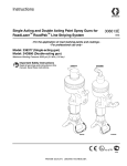
Operation
Single Acting and Double Acting Bead Spray Guns for
RoadLazer™ RoadPak™ Line Striping System
308612J
EN
- For the application of road marking reflective materials - For professional use only -
Model: 238338 - Single Acting Bead Spray Gun
Model: 24G979 - Double Acting Bead Spray Gun
200 psi (1.38 MPa, 13.8 bar) Maximum Working Pressure
Important Safety Instructions
Read all warnings and instructions in this
manual. Save these instructions.
Single Acting Bead Spray Gun
Double Acting Bead Spray Gun
5949b
ti16176b
II 2 G T5
Warnings
Warnings
The following warnings are for the setup, use, grounding, maintenance, and repair of this equipment. The exclamation point symbol alerts you to a general warning and the hazard symbols refer to procedure-specific risks. When
these symbols appear in the body of this manual, refer back to these Warnings. Product-specific hazard symbols and
warnings not covered in this section may appear throughout the body of this manual where applicable.
WARNING
WARNING
EQUIPMENT MISUSE HAZARD
Misuse can cause death or serious injury.
• Do not operate the unit when fatigued or under the influence of drugs or alcohol.
• Do not exceed the maximum working pressure or temperature rating of the lowest rated system
component. See Technical Data in all equipment manuals.
• Use fluids and solvents that are compatible with equipment wetted parts. See Technical Data in all
equipment manuals. Read fluid and solvent manufacturer’s warnings. For complete information about
your material, request MSDS from distributor or retailer.
• Do not leave the work area while equipment is energized or under pressure. Turn off all equipment
and follow the Pressure Relief Procedure when equipment is not in use.
• Check equipment daily. Repair or replace worn or damaged parts immediately with genuine
manufacturer’s replacement parts only.
• Do not alter or modify equipment.
• Use equipment only for its intended purpose. Call your distributor for information.
• Route hoses and cables away from traffic areas, sharp edges, moving parts, and hot surfaces.
• Do not kink or over bend hoses or use hoses to pull equipment.
• Keep children and animals away from work area.
• Comply with all applicable safety regulations.
PERSONAL PROTECTIVE EQUIPMENT
You must wear appropriate protective equipment when operating, servicing, or when in the operating area
of the equipment to help protect you from serious injury, including eye injury, hearing loss, inhalation of
toxic fumes, and burns. This equipment includes but is not limited to:
• Protective eyewear, and hearing protection.
• Respirators, protective clothing, and gloves as recommended by the fluid and solvent manufacturer.
CALIFORNIA PROPOSITION 65
The engine exhaust from this product contains a chemical known to the State of California to cause
cancer, birth defects or other reproductive harm.
2
308612J
Installation
Installation
Accessories are available from Graco. Be sure all
accessories are properly sized to withstand the pressures in the system.
Connect Material Line
Mount Valve
Mount the valve on a 0.50 in. (12.7 mm) diameter rod on
a mounting fixture or a dispensing machine. The bead
gun has a clamping set screw for mounting.
ti16200b
Grounding
Proper grounding is essential to maintaining a safe system.
ti16199b
To reduce the risk of static sparking, ground the pump,
bead spray gun, paint spray gun and all other system
equipment.
Connect the Air Lines
1. Pump: Use a ground wire and clamp.
2. Air compressors and hydraulic power supplies:
Follow manufacturer’s recommendations.
3. Air and fluid hoses connected to the pump: Use
only grounded hoses with a maximum of 500 feet
(150 m) combined hose length to ensure grounding
continuity.
ti16198b
ti16177b
Single-Acting Gun
Double-Acting Gun
Clean all lines and connections of dirt, burrs, etc. and
blow them out with clean air before connecting them to
the system. Install an air filter in the air supply line to
remove harmful dirt and moisture from the compressed
air.
308612J
4. Dispensing valve: Obtain grounding through connection to a properly grounded fluid hose, frame,
and pump.
5. Fluid supply container: According to local code.
6. All solvent pails used when flushing: Ground
according to local code. Use only metal pails, which
are conductive. Do not place the pail on a non conductive surface, such as paper or cardboard, which
interrupts the grounding continuity.
3
Operation
Operation
Pressure Relief Procedure
Application Data
See RoadLazer System manual 3A1214.
Nozzle Size Selection
1. Shut off air supply to the bead tank. Relieve pressure from bead tank.
2. Close the master air valve (required with air-powered pumps).
3. Actuate the dispensing valve to relieve pressure.
4. Leave the drain valve(s) open until you are ready to
dispense again.
If you suspect that the dispensing valve or hose is completely clogged, or that pressure has not been fully
relieved after following the steps above, very slowly
loosen the hose end coupling and relieve pressure gradually, then loosen completely. Then clear the valve or
hose.
Use the Nozzle Size Selection and Bead Delivery
Tables to select the size of nozzle for the travel speed
and bead coverage to be used. These tables are based
on a 15 mil paint application.
1. Go to Bead Delivery (Lb/Min) Table and select:
a. Speed in MPH or KPH row.
b. Bead coverage in Pounds Per Gallon (kg/l)
column.
c.
Value at intersection of MPH (KPH) row and
Pounds Per column is bead delivery in lb/min
(kg/min).
2. Go to Nozzle Size Selection Table and select:
Adjustments
a. Bead Delivery lb/min (kg/min) column determined by Bead delivery lb/min (kg/min) value.
Set the actuating air to at least 50 psi (3.5 bar) for single
acting gun and 80 psi (5.5 bar) for double acting gun,
then start the pump. Set the glass bead supply tank
pressure between 30 psi (2.1 bar) and 75 psi (5.2 bar)
for desired flow rate.
b. Psi value Glass Bead Tank psi (bar) row.
NOTE: Bead delivery will very with each application.
Always test the system for actual delivery and adjust air
pressure or nozzle size as needed.
d. Select nozzle size that allows range of adjustment for more or less flow.
4
c.
Curve (1, 2, 3 or 4) at intersection of Glass
Bead Tank psi row and Bead Delivery lb/min
(kg/min) column is nozzle size value.
NOTE: If dispensing reflective elements for double drop
application, the minimum nozzle size is .280 in. If a
smaller size is used, clogging of the nozzle orifice may
occur.
308612J
Operation
Bead Delivery lb/min (kg/min)
Speed
Bead Coverage in Pounds Per Gallon (kg/l)
MPH
KPH
4 (.48)
5 (.60)
6 (.72)
7 (.84)
8 (.96)
9 (1.08)
2
3.2
2.4 (1.09)
3.0 (1.36)
3.6 (1.63)
4.1 (1.86)
4.7 (2.13)
5.3 (2.40)
3
4.8
3.6 (1.63)
4.4 (2.0)
5.3 (2.40)
6.2 (2.81)
7.1 (3.22)
8.0 (3.62)
4
6.4
4.7 (2.13)
5.9 (2.68)
7.1 (3.22)
8.3 (3.76)
9.5 (4.31)
10.7 (4.85)
5
8.0
5.9 (2.68)
7.4 (3.36)
8.9 (4.04)
10.4 (4.72)
11.9 (5.40)
13.3 (6.03)
6
9.6
7.1 (3.22)
8.9 (4.04)
10.7 (4.85)
12.4 (5.62)
14.2 (6.44)
16.0 (7.26)
7
11.2
8.3 (3.76)
10.4 (4.72)
12.4 (5.62)
14.5 (6.58)
16.6 (7.53)
18.7 (8.48)
8
12.8
9.5 (4.31)
11.9 (5.40)
14.2 (6.44)
16.6 (7.53)
19.0 (8.62)
21.3 (9.66)
9
14.4
10.7 (4.85)
13.3 (6.03)
16.0 (7.26)
18.7 (8.48)
21.3 (9.66)
24.0 (10.9)
10
16.0
11.9 (5.40)
14.8 (6.71)
17.8 (8.07)
20.7 (9.39)
23.7 (10.8)
26.7 (12.1)
11
17.6
13.0 (5.90)
16.3 (7.39)
19.6 (8.89)
22.8 (10.3)
26.1 (11.8)
29.3 (13.3)
12
19.2
14.2 (6.44)
17.8 (8.07)
21.3 (9.66)
24.9 (11.3)
28.4 (12.9)
32.0 (14.5)
Nozzle Size Selection
(4.76) 70
1
Glass Bead Tank psi (bar)
(4.08) 60
2
3
4
5
(3.40) 50
(2.72) 40
(2.04) 30
(1.36) 20
(0.68) 10
0
0
5
(2.27)
10
(4.54)
15
(6.80)
20
(9.07)
25
(11.3)
30
(13.6)
35
(15.9)
40
(18.2)
45
(20.4)
Bead Delivery lb/min (kg/min)
Orifice Diameter:
1 0.203 3 0.280
2 0.234
308612J
4 0.344
5 0.420
5
Maintenance
Maintenance
2. Remove valve housing:
Clean Dispensing Valve and
System Daily
a. Remove cap and spring.
Clean the outside of the valve by wiping with a soft cloth
dampened with a compatible solvent.
NOTICE
Never immerse the entire dispensing valve in solvent.
Immersing in solvent removes lubricants and can
damage packings.
ti16182a
b. Loosen nut.
To remove a hardened particle from the orifice, blow air
through the orifice from the front.
Oil Dispensing Valve Daily
Before each use, lubricate with a spray of oil inside the
protection tube (13) to prevent fluid buildup on these
parts. Any buildup could damage the valve packings
(16, 17, 18).
ti16179a
c.
Pull down housing and needle assembly to
expose needle shaft.
ti16180a
d. Slide needle through air piston to remove.
ti16188b
Service
ti16192a
Needle, Seat and Packings
3. Remove retaining nut.
To clean or replace the needle, seat or packings, proceed as follows:
1. Follow Pressure Relief Procedure on page 4.
ti16184b
6
308612J
Service
4. Remove valve seat and o-ring from valve housing
and remove gun needle.
9. Install o-ring on valve seat and insert into valve
housing.
ti16191a
ti16185a
ti16183a
10. Install retaining nut.
5. Remove seal nut and o-ring.
ti16190b
ti16195a
6. Clean all parts. Inspect o-rings for signs of wear,
replace as necessary.
Air Piston, Spring and Seals
1. Perform Pressure Relief Procedure, page 4.
2. Remove valve housing (step 2, page 6).
3. Pull out piston and spring guide, then clean and
inspect all parts.
Double Acting
ti16194a
Single Acting
7. Lubricate o-ring with one drop of oil. Install o-ring.
ti16197a
8. Install seat nut, o-ring, and gun needle.
ti16187a
ti16196a
ti16189a
308612J
ti17002a
Check the piston o-rings carefully. Lubricate all parts
with a light waterproof grease and reassemble the valve
using new parts as necessary.
7
Troubleshooting
Troubleshooting
NOTE: Check all possible solutions before disassembling the pump.
Problem
Solution
Uneven spray pattern
Bead pressure too low
Increase pressure to bead tank, or adjust
bead pressure regulator
Spray gun will not stop spraying
Gun needle binding
Clean, repair
Obstructed or worn needle seat
Clean or replace
Bead line clogged
Clear
Bead valve closed
Open
Clogged orifice or needle seat
Clean
No trigger or actuator air pressure
Check, clean air lines
Wet beads
Drain beads from tank and replace with dry
beads
Spray gun will not spray
8
Cause
308612J
Replacement Parts and Kits (Single Acting Gun)
Replacement Parts and Kits (Single Acting Gun)
Model 238338
Parts List
Ref.
2**
3
4
5
6
7
8
9
11*
12*
13*
14
15*
16
17
18*
19**
20
21*
22
7
8
9
11
10
12
5
6
13*
14
28
Part
191201
191196
191206
166847
101554
191197
164739
164740
156593
155685
191195
102300
158486
191192
166702
127285
238341
24J173
Description
Qty.
SEAT, valve
1
NUT, retaining
1
HOUSING, valve
1
HOUSING, valve
1
SET SCREW, 3/8-16 x 3/4 in.
1
CAP, air cylinder
1
SPRING
1
GUIDE, spring
1
O-RING, nitrile rubber
1
PACKING, o-ring
1
TUBE, protection
1
NUT, jam, 7/8 inc. hex
1
PACKING, o-ring
1
NUT, packing
1
SEAL, needle
1
NEEDLE, gun
1
O-RING
1
RING, retaining, external
1
NUT, seal (includes 16, 17)
1
BEAD DEFLECTOR,
1
adjustable (includes 3, 20)
4
* Included in Repair Kit 238340. Order separately.
** RoadLazer ships with 3 Valve Seat and O-Ring
kits listed in the following table.
15
16
21*
17
18
19**
20
2**
3
22
ti17001c
308612J
9
Replacement Parts and Kits (Double Acting Gun)
Replacement Parts and Kits (Double Acting Gun)
Model 24G979
Parts List
27
Ref.
2**
3
4
5
6
7
8
9
11*
12*
13*
14
15*
16
17
18*
19**
20
21*
22
7
9
8
23*
11
10
12
5
13*
6
14
Part
191201
191196
191206
166847
101554
16G708
16G763
16G169
156593
155685
191195
102300
158486
191192
166702
127285
238341
24J173
23* C20179
27 112698
28 114109
28
4
Description
Qty.
SEAT, valve
1
NUT, retaining
1
HOUSING, valve
1
HOUSING, valve
1
SET SCREW, 3/8-16 x 3/4 in.
1
CAP, cylinder
1
SPRING, compression
1
GUIDE, spring
1
O-RING, nitrile rubber
1
PACKING, o-ring
1
TUBE, protection
1
NUT, jam, 7/8 inc. hex
1
PACKING, o-ring
1
NUT, packing
1
SEAL, needle
1
NEEDLE, gun
1
O-RING
1
RING, retaining, external
1
NUT, seal (includes 16, 17)
1
BEAD DEFLECTOR,
1
adjustable (includes 3, 20)
O-RING
1
1/8 in. npt male swivel elbow
1
1/4 in. npt male swivel elbow
1
* Included in Repair Kit 238340. Order separately.
** RoadLazer ships with 3 Valve Seat and O-Ring
kits listed in the following table
15
16
21*
17
18
20
3
19**
2**
22
ti16178c
10
308612J
Replacement Parts and Kits (Double Acting Gun)
Valve Seat and O-Ring Kits
Valve Seat Nozzle Size
Kit (Includes O-Ring)
0.203
238663
0.234
238666
0.281
238664
0.344
238665
0.420 †
243668
† Nozzle size 0.420 is optional; order separately
Accessories
Adjustable Bead Deflector Kit - 24J173
Allows application of 12 in. wide beaded lines.
Technical Data
Single Acting Bead Spray Gun
238338
Maximum working pressure
Double Acting Bead Spray Gun
24G979
200 psi (12 bar)
Operating pressure of air actuated trigger
(Single Acting Bead Gun):
Minimum
Maximum
Air connection
Bead connection
Glass bead output
Air consumption
Spray width
Operating temperature
50 psi (3 bar)
200 psi (12 bar)
80 psi (5.5 bar)
200 psi (12 bat)
1/4 npt(f) air inlet
3/4 npt(f) bead inlet
2-40 lb/min (0.9-18 kg/min)
1-2 cfm
2-12 in. (50-304mm)
32° - 120° F
(0° - 49° C)
Sound pressure level
<80 dB
Sound power level
<80 dB
*Measurements at 120 psi Air Cylinder, 60 psi Air Bead
308612J
11
Graco Standard Warranty
Graco warrants all equipment referenced in this document which is manufactured by Graco and bearing its name to be free from defects in
material and workmanship on the date of sale to the original purchaser for use. With the exception of any special, extended, or limited warranty
published by Graco, Graco will, for a period of twelve months from the date of sale, repair or replace any part of the equipment determined by
Graco to be defective. This warranty applies only when the equipment is installed, operated and maintained in accordance with Graco’s written
recommendations.
This warranty does not cover, and Graco shall not be liable for general wear and tear, or any malfunction, damage or wear caused by faulty
installation, misapplication, abrasion, corrosion, inadequate or improper maintenance, negligence, accident, tampering, or substitution of
non-Graco component parts. Nor shall Graco be liable for malfunction, damage or wear caused by the incompatibility of Graco equipment with
structures, accessories, equipment or materials not supplied by Graco, or the improper design, manufacture, installation, operation or
maintenance of structures, accessories, equipment or materials not supplied by Graco.
This warranty is conditioned upon the prepaid return of the equipment claimed to be defective to an authorized Graco distributor for verification of
the claimed defect. If the claimed defect is verified, Graco will repair or replace free of charge any defective parts. The equipment will be returned
to the original purchaser transportation prepaid. If inspection of the equipment does not disclose any defect in material or workmanship, repairs will
be made at a reasonable charge, which charges may include the costs of parts, labor, and transportation.
THIS WARRANTY IS EXCLUSIVE, AND IS IN LIEU OF ANY OTHER WARRANTIES, EXPRESS OR IMPLIED, INCLUDING BUT NOT
LIMITED TO WARRANTY OF MERCHANTABILITY OR WARRANTY OF FITNESS FOR A PARTICULAR PURPOSE.
Graco’s sole obligation and buyer’s sole remedy for any breach of warranty shall be as set forth above. The buyer agrees that no other remedy
(including, but not limited to, incidental or consequential damages for lost profits, lost sales, injury to person or property, or any other incidental or
consequential loss) shall be available. Any action for breach of warranty must be brought within two (2) years of the date of sale.
GRACO MAKES NO WARRANTY, AND DISCLAIMS ALL IMPLIED WARRANTIES OF MERCHANTABILITY AND FITNESS FOR A
PARTICULAR PURPOSE, IN CONNECTION WITH ACCESSORIES, EQUIPMENT, MATERIALS OR COMPONENTS SOLD BUT NOT
MANUFACTURED BY GRACO. These items sold, but not manufactured by Graco (such as electric motors, switches, hose, etc.), are subject to
the warranty, if any, of their manufacturer. Graco will provide purchaser with reasonable assistance in making any claim for breach of these
warranties.
In no event will Graco be liable for indirect, incidental, special or consequential damages resulting from Graco supplying equipment hereunder, or
the furnishing, performance, or use of any products or other goods sold hereto, whether due to a breach of contract, breach of warranty, the
negligence of Graco, or otherwise.
FOR GRACO CANADA CUSTOMERS
The Parties acknowledge that they have required that the present document, as well as all documents, notices and legal proceedings entered into,
given or instituted pursuant hereto or relating directly or indirectly hereto, be drawn up in English. Les parties reconnaissent avoir convenu que la
rédaction du présente document sera en Anglais, ainsi que tous documents, avis et procédures judiciaires exécutés, donnés ou intentés, à la suite
de ou en rapport, directement ou indirectement, avec les procédures concernées.
Graco Information
For the latest information about Graco products, visit www.graco.com.
TO PLACE AN ORDER, contact your Graco distributor or call 1-800-690-2894 to identify the nearest distributor.
All written and visual data contained in this document reflects the latest product information available at the time of publication.
Graco reserves the right to make changes at any time without notice.
For patent information, see www.graco.com/patents.
Original instructions. This manual contains English. MM 308612
Graco Headquarters: Minneapolis
International Offices: Belgium, China, Japan, Korea
GRACO INC. AND SUBSIDIARIES • P.O. BOX 1441 • MINNEAPOLIS MN 55440-1441 • USA
Copyright 1996, Graco Inc. All Graco manufacturing locations are registered to ISO 9001.
www.graco.com
Revised October 2014