1
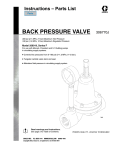
Instructions – Parts List
Parts
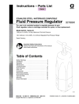
MODEL LSPBR 1000T
STAINLESS STEEL, LOW SHEAR, WATERBASE COMPATIBLE
Back Pressure Regulator
300 psi (2.1 MPa, 21 bar) Maximum Working Pressure
200 psi (1.4 MPa, 14 bar) Maximum Regulated Pressure
4 GPM (15 L/min) Minimum Fluid Flowrate
For use in circulating air spray systems only
Part No. 223824, Series B
With 2 inch sanitary clamp
Part No. 224486. Series B
With 1–1/2 inch npt(f) fittings
For use with waterbase fluids in circulating
air spray systems. Provides regulated back
pressure to the spray gun(s) and maintains
proper circulating pressure throughout the
system.
U.S. and Foreign Patents Pending
Read warnings and instructions.
See page 2 for table of contents.
GRACO INC.ąP.O. BOX 1441ąMINNEAPOLIS, MNą55440-1441
Copyright 1990, Graco Inc. is registered to I.S. EN ISO 9001
308115J
Table of Contents
Warnings . . . . . . . . . . . . . . . . . . . . . . . . . . . . . . . . . . . . . .
Installation . . . . . . . . . . . . . . . . . . . . . . . . . . . . . . . . . . . . .
Operation . . . . . . . . . . . . . . . . . . . . . . . . . . . . . . . . . . . . .
Service . . . . . . . . . . . . . . . . . . . . . . . . . . . . . . . . . . . . . . .
Parts . . . . . . . . . . . . . . . . . . . . . . . . . . . . . . . . . . . . . . . . .
Dimensions . . . . . . . . . . . . . . . . . . . . . . . . . . . . . . . . . . . .
Technical Data . . . . . . . . . . . . . . . . . . . . . . . . . . . . . . . . .
Graco Standard Warranty . . . . . . . . . . . . . . . . . . . . . . .
Graco Information . . . . . . . . . . . . . . . . . . . . . . . . . . . . . .
Symbols
2
3
4
5
6
7
7
8
8
Warning Symbol
WARNING
This symbol alerts you to the possibility of serious
injury or death if you do not follow the instructions.
Caution Symbol
CAUTION
This symbol alerts you to the possibility of damage to
or destruction of equipment if you do not follow the
corresponding instructions.
WARNING
EQUIPMENT MISUSE HAZARD
INSTRUCTIONS
Equipment misuse can cause the equipment to rupture, malfunction, or start unexpectedly and result
in a serious injury.
D This equipment is for professional use only.
D Read all the instruction manuals, tags, and labels before operating the equipment.
D Use the equipment only for its intended purpose. If you are uncertain about usage, call your Graco
distributor.
D Do not alter or modify this equipment. Use only genuine Graco parts and accessories.
D Check the equipment daily. Repair or replace worn or damaged parts immediately.
D Do not exceed the maximum pressure of the lowest rated system component. This equipment has
a 300 psi (2.1 MPa, 21 bar) maximum inlet pressure and a 30 psi (210 kPa, 2.1 bar) maximum
static fluid pressure.
D Use fluids that are compatible with the equipment wetted parts. See the Technical Data section of
all the equipment manuals. Read the fluid manufacturer’s warnings.
D Route the hoses away from traffic areas, sharp edges, moving parts, and hot surfaces. Do not
expose Graco hoses to temperatures above 180_F (82_C) or below –40_F (–40_C).
D Comply with all applicable local, state, and national fire, electrical, and other safety regulations.
PRESSURIZED EQUIPMENT HAZARD
Spray from the gun, hose leaks, or ruptured components can splash fluid in the eyes or on the skin
and cause serious injury.
D Do not stop of deflect fluid leaks with your hand, body, glove, or rag.
D Follow the Pressure Relief Procedure in your separate equipment manuals whenever you: are
instructed to relieve pressure; stop spraying; clean, check, or service the equipment; and install or
clean the spray tip.
D Tighten all the fluid connections before operating the equipment.
D Check the hoses, tubes, and couplings daily. Replace worn, damaged, or loose parts immediately.
Permanently coupled hoses cannot be repaired; replace the entire hose.
2
308115
Installation
FLUID SUPPLY LINE
FLUID PRESSURE REGULATOR
AIR SUPPLY
AIR
SPRAY
GUN
ADJUSTING
SCREW
BACK
PRESSURE
REGULATOR
FLUID RETURN LINE
Fig. 1
Installing the Back Pressure Regulator
The regulator is available with either 2 in. sanitary
clamps (Model 223824) or with 1–1/2 in. npt(f) fittings
(Model 224486). Be sure to order the regulator with the
type of end fittings required. The fittings should not
need to be removed or replaced during installation.
WARNING
If the end fittings are loosened or removed, be sure
to torque them to 100 to 110 ft-lb (135 to 150 NSm)
when they are tightened or installed. Failure to do
so could cause fluid to discharge and result in
serious injury or property damage.
CAUTION
To avoid fluid leakage, use only Graco Fitting Kits
916331 or 916343 when installing Model 223824
regulator.
Install the back pressure regulator in the spray gun
return line. See Fig. 1. Connect the fluid line to the inlet
and outlet fittings, making sure the flow direction
agrees with the IN and OUT markings on the regulator
body.
CAUTION
The fluid flow direction must agree with the IN and
OUT markings on the regulator body. Failure to do
so will damage the back pressure regulator.
The back pressure regulator is adjustable to control
the fluid pressures in a circulating system from 15 to
200 psi (0.1 to 1.4 MPa, 1 to 14 bar).
If more than one spray station is used, install the back
pressure regulator in the fluid supply line after the last
station. This will help maintain proper circulating pressures in the system.
CAUTION
To avoid excessive wear on the diaphragm, regulator
inlet pressure should not be allowed to pulsate
greater then +/– 5% of nominal pressure.
308115
3
Operation
NOTE: The back pressure regulator controls pressure
ahead of its intake.
Turn the adjusting screw clockwise to increase upstream pressure and counterclockwise to decrease
pressure.
Flush the back pressure regulator with a compatible
solvent whenever the rest of the system or unit is
being flushed. Open the back pressure regulator
before flushing by turning the screw counterclockwise.
CAUTION
To avoid damaging the diaphragm
Adjust the pump pressure and back pressure regulator
for the best spraying combination and for proper
circulation of fluid. Turn the back pressure regulator’s
adjusting screw fully clockwise, so fluid flow is minimal
and back pressure is at maximum, before beginning
adjustment.
4
308115
1. Never back flush.
2. If an external pump is used to flush, make sure
the inlet pressure to the back pressure regulator
does not exceed 30 psi (210 kPa, 2.1 bar).
Service
WARNING
5. Install the diaphragm parts onto the regulator
base (9).
To reduce the risk of serious injury, including fluid
injection, splashing in the eyes or on the skin, or
injury from moving parts, always open the back
pressure regulator and relieve all air and fluid
pressures in the system before removing or servicing the back pressure regulator.
Lubricate the parts as indicated in the Parts Drawing on page 6.
NOTE: Regulator an inspection of the regulator, based
upon the degree and kind of service, is essential.
CAUTION
1. Shut off the pump and open the back pressure
regulator by turning the adjustment screw (15)
counterclockwise until no spring pressure is felt.
Relieve all air and fluid pressures in the system.
NOTE: The back pressure regulator can either be
serviced while it remains in the fluid line or it can be
removed from the line for servicing.
2. Disassemble the regulator and clean it with a
suitable solvent. See the Parts Drawing on
page 6.
3. Carefully inspect the diaphragm (10) for cracks or
other damage. Replace if necessary.
4. Check the parts for chips or dirt before assembling
the regulator.
Tighten the cover screws (2) finger tight, then
torque them to 70 to 90 in-lb (8.0 to 10.2 NSm) in a
criss-cross pattern. See the TOP VIEW in the
Parts Drawing.
Do not lubricate the parts with silicone grease.
Silicone grease will contaminate the fluid and blemish the finish of the surface being painted.
6. Tighten the regulator cap screws (2) finger tight,
then torque them to 70 to 90 in-lb (8.0 to 10.2
NSm) in a criss-cross pattern. See the TOP VIEW
in the Parts Drawing
7. To remove or install the gauge (8), use the wrench
on the square portion of the gauge stud only. Use
thread sealer sparingly on the gauge’s male
threads when install it to avoid plugging the gauge.
8. Install the back pressure regulator back in the fluid
line.
WARNING
If the end fittings (16) are loosened or removed, be
sure to torque them to 100 to 110 ft-lb (135 to 150
NSm) when they are tightened or installed. Failure
to do so could cause fluid to discharge and result in
serious injury or property damage.
308115
5
Parts
Model 223824, Series B
With 2 in. sanitary clamp fittings. Includes 2 to 22.
Model 224486, Series B
With 1–1/2 in. npt(f) fittings. Includes 2 to 15, 22,
and 24.
15
1
2
3
14
2
7
2
3
13
3
2
Ref
No.
Part No.
Description
2
3
4†
5†
7
8*
112166
104144
107078
111331
160033
187873
9
10†
11
12
13
14
15
16
22
24
186866
190849
186868
190857
186870
186871
186872
187004
187223
187150
SCREW, cap, sch; 1/4–20 x 3/4”
SPRING, compression
O-RING, PTFE
O-RING, PTFE
PLATE, spring
GAUGE, 0 to 200 psi
(0 to 1.4 MPa, 0 to 14 bar)
BASE, regulator
DIAPHRAGM
PLATE, diaphragm
BEARING
COVER, diaphragm
CAP
SCREW, adjustment
FITTING, 2” sanitary clamp
PLATE, warning
FITTING, 1–1/2” npt(f)
Qty.
† These parts are included in repair kit 224437. Note that the
kit includes one new-style PTFE 0-ring, Part No. 111331 (Ref.
5), & one old-style PTFE O-ring, Part No. 111278.
CAUTION
12
Do not lubricate the parts with silicone grease.
Silicone grease will contaminate the fluid and blemish the finish of the surface being painted.
11
10
Torque diaphragm cover screws and
cap screws in a criss-cross pattern to
70 to 90 in-lb (8.0 to 10.2 NSm).
5
3
2
5
6
1
4
9
8
4
6
308115
16
1
1
1
1
1
1
1
1
2
1
2
* Recommended Tool Box spare parts. Keep these spare
parts on hand to reduce down time.
22
0690A
18
1
2
1
1
1
4
16
4
TOP VIEW
1
4
1
Lubricate threads with light grease.
2
Lubricate with lithium-base grease.
3
See TOP VIEW.
4
Torque to 100 to 110 ft-lbs (135 to 150 NSm)
Dimensions
7 in. (178 mm)
diameter
OUT
11.5 in.
(292 mm)
10.71 in.
(272 mm)
IN
2 in. (51 mm)
sanitary clamp fitting
INLET and OUTLET
Weight: 19 lb (8.55 kg)
0689A
Technical Data
Maximum Inlet Pressure
300 psi (2.1 MPa, 21 bar)
Regulated Pressure Range
15 to 200 psi (0.03 to 1.4 MPa, 0.3 to 14 bar)
Inlet and Outlet Size: Model 223824
2 in. sanitary clamp fitting
Inlet and Outlet Size: Model 224486
1–1/2 in. npt(f) fitting
Gauge Port Size
1/4 npt(f)
Wetted Parts
301, 304 & 316 Stainless Steel, PTFE
Minimum Fluid Flowrate
4 GPM (15 L/min)
308115
7
Graco Standard Warranty
Graco warrants all equipment manufactured by Graco and bearing its name to be free from defects in material and workmanship on the
date of sale by an authorized Graco distributor to the original purchaser for use. With the exception of any special, extended, or limited
warranty published by Graco, Graco will, for a period of twelve months from the date of sale, repair or replace any part of the equipment
determined by Graco to be defective. This warranty applies only when the equipment is installed, operated and maintained in accordance with Graco’s written recommendations.
This warranty does not cover, and Graco shall not be liable for general wear and tear, or any malfunction, damage or wear caused by
faulty installation, misapplication, abrasion, corrosion, inadequate or improper maintenance, negligence, accident, tampering, or substitution of non-Graco component parts. Nor shall Graco be liable for malfunction, damage or wear caused by the incompatibility of
Graco equipment with structures, accessories, equipment or materials not supplied by Graco, or the improper design, manufacture,
installation, operation or maintenance of structures, accessories, equipment or materials not supplied by Graco.
This warranty is conditioned upon the prepaid return of the equipment claimed to be defective to an authorized Graco distributor for
verification of the claimed defect. If the claimed defect is verified, Graco will repair or replace free of charge any defective parts. The
equipment will be returned to the original purchaser transportation prepaid. If inspection of the equipment does not disclose any defect
in material or workmanship, repairs will be made at a reasonable charge, which charges may include the costs of parts, labor, and
transportation.
THIS WARRANTY IS EXCLUSIVE, AND IS IN LIEU OF ANY OTHER WARRANTIES, EXPRESS OR IMPLIED, INCLUDING BUT
NOT LIMITED TO WARRANTY OF MERCHANTABILITY OR WARRANTY OF FITNESS FOR A PARTICULAR PURPOSE.
Graco’s sole obligation and buyer’s sole remedy for any breach of warranty shall be as set forth above. The buyer agrees that no other
remedy (including, but not limited to, incidental or consequential damages for lost profits, lost sales, injury to person or property, or any
other incidental or consequential loss) shall be available. Any action for breach of warranty must be brought within two (2) years of the
date of sale.
Graco makes no warranty, and disclaims all implied warranties of merchantability and fitness for a particular purpose in connection
with accessories, equipment, materials or components sold but not manufactured by Graco. These items sold, but not manufactured
by Graco (such as electric motors, switches, hose, etc.), are subject to the warranty, if any, of their manufacturer. Graco will provide
purchaser with reasonable assistance in making any claim for breach of these warranties.
In no event will Graco be liable for indirect, incidental, special or consequential damages resulting from Graco supplying equipment
hereunder, or the furnishing, performance, or use of any products or other goods sold hereto, whether due to a breach of contract,
breach of warranty, the negligence of Graco, or otherwise.
FOR GRACO CANADA CUSTOMERS
The parties acknowledge that they have required that the present document, as well as all documents, notices and legal proceedings
entered into, given or instituted pursuant hereto or relating directly or indirectly hereto, be drawn up in English. Les parties reconnaissent avoir convenu que la rédaction du présente document sera en Anglais, ainsi que tous documents, avis et procédures judiciaires
exécutés, donnés ou intentés à la suite de ou en rapport, directement ou indirectement, avec les procedures concernées.
Graco Information
TO PLACE AN ORDER, contact your Graco distributor, or call one of the following numbers
to identify the distributor closest to you:
1–800–328–0211 Toll Free
612–623–6921
612–378–3505 Fax
All written and visual data contained in this document reflects the latest product information available at the time of publication.
Graco reserves the right to make changes at any time without notice.
Sales Office: Minneapolis
International Offices: Belgium, Korea, China, Japan
www.graco.com
PRINTED IN USA 308115 12/1990, Revised12/2004
8
308115