1
Instructions–Parts List
HYDRA–SPRAYR
Monarkr and Presidentr
Pumps
307619ZAA
ENG
For airless and air–assisted spraying of finishing materials.
For professional use only.
Important Safety Instructions
Read all warnings and instructions in this manual. Save
these instructions.
See page 2 for Table of Contents
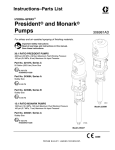
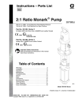
Part No. 223596, Series B 23:1 Ratio Monarkr Pump
with Part No. 223595 carbon steel severe–duty displacement pump*
with stainless steel glands, intake housing, piston valve, and ball stop
2760 psi (19 MPa, 190 bar) Maximum Fluid Working Pressure
120 psi (0.8 MPa, 8 bar) Maximum Air Input Pressure
II 1/2 G T3
ITS03ATEX11228
Part No. 237958, Series B 23:1 Ratio Monarkr Pump
with Part No. 239145 stainless steel
severe–duty displacement pump*
3450 psi (24 MPa, 238 bar) Maximum Fluid Working Pressure
150 psi (1.0 MPa, 10.4 bar) Maximum Air Input Pressure
II 1/2 G T3
ITS03ATEX11228
Part No. 239140, Series A 46:1 Ratio Presidentr Pump
with Part No. 239145 stainless steel
severe–duty displacement pump*
06936
4600 psi (32 MPa, 317 bar) Maximum Fluid Working Pressure
100 psi (0.7 MPa, 7 bar) Maximum Air Input Pressure
Model 239140
II 2 G T6
*
Severe–duty displacement pumps have abrasion–resistant
displacement rods and sleeves. Refer to Technical Data on
page 20 for information on the wetted parts.
Model 223596
02097
Table of Contents
Warnings . . . . . . . . . . . . . . . . . . . . . . . . . . . . . . . . . . . . . . 2
Installation . . . . . . . . . . . . . . . . . . . . . . . . . . . . . . . . . . . . . 5
Operation . . . . . . . . . . . . . . . . . . . . . . . . . . . . . . . . . . . . . 8
Troubleshooting . . . . . . . . . . . . . . . . . . . . . . . . . . . . . . . 10
Service
Disconnecting the Displacement Pump . . . . . . . . 11
Reconnecting the Displacement Pump . . . . . . . . 11
Displacement Pump Service . . . . . . . . . . . . . . . . . 12
Parts . . . . . . . . . . . . . . . . . . . . . . . . . . . . . . . . . . . . . . . .
Conversion Kits . . . . . . . . . . . . . . . . . . . . . . . . . . . . . . .
Dimensions . . . . . . . . . . . . . . . . . . . . . . . . . . . . . . . . . . .
Mounting Hole Layout . . . . . . . . . . . . . . . . . . . . . . . . . .
Technical Data . . . . . . . . . . . . . . . . . . . . . . . . . . . . . . . .
Graco Standard Warranty . . . . . . . . . . . . . . . . . . . . . .
Graco Information . . . . . . . . . . . . . . . . . . . . . . . . . . . . .
14
18
19
19
20
24
24
WARNING
EQUIPMENT MISUSE HAZARD
Equipment misuse can cause the equipment to rupture or malfunction and result in serious injury.
INSTRUCTIONS
D This equipment is for professional use only.
D Read all instruction manuals, tags, and labels before operating the equipment.
D Use the equipment only for its intended purpose. If you are uncertain about usage, call your Graco
distributor.
D Do not alter or modify this equipment. Use only genuine Graco parts and accessories.
D Check equipment daily. Repair or replace worn or damaged parts immediately.
D Do not exceed the maximum working pressure of the lowest rated system component. Refer to the
Technical Data on page 20 for the maximum working pressure of this equipment.
D Use fluids and solvents which are compatible with the equipment wetted parts. Refer to the Technical Data section of all equipment manuals. Read the fluid and solvent manufacturer’s warnings.
D Do not use hoses to pull equipment.
D Route hoses away from traffic areas, sharp edges, moving parts, and hot surfaces. Do not expose
Graco hoses to temperatures above 180_F (82_C) or below –40_F (–40_C).
D Wear hearing protection when operating this equipment.
D Do not lift pressurized equipment.
D Comply with all applicable local, state, and national fire, electrical, and safety regulations.
2
307619
WARNING
SKIN INJECTION HAZARD
Spray from the gun, hose leaks, or ruptured components can inject fluid into your body and cause
extremely serious injury, including the need for amputation. Fluid splashed in the eyes or on the skin
can also cause serious injury.
D Fluid injected into the skin might look like just a cut, but it is a serious injury. Get immediate
surgical treatment.
D Do not point the gun at anyone or at any part of the body.
D Do not put your hand or fingers over the spray tip.
D Do not stop or deflect leaks with your hand, body, glove or rag.
D Do not “blow back” fluid; this is not an air spray system.
D Always have the tip guard and the trigger guard on the gun when spraying.
D Check the gun diffuser operation weekly. Refer to the gun manual.
D Be sure the gun trigger safety operates before spraying.
D Lock the gun trigger safety when you stop spraying.
D Follow the Pressure Relief Procedure on page 8 whenever you: are instructed to relieve pressure; stop spraying; clean, check, or service the equipment; and install or clean the spray tip.
D Tighten all fluid connections before operating the equipment.
D Check the hoses, tubes, and couplings daily. Replace worn, damaged, or loose parts immediately.
Permanently coupled hoses cannot be repaired; replace the entire hose.
D Use only Graco approved hoses. Do not remove any spring guard that is used to help protect the
hose from rupture caused by kinks or bends near the couplings.
MOVING PARTS HAZARD
Moving parts, such as the air motor piston, can pinch or amputate your fingers.
D Keep clear of all moving parts when starting or operating the pump.
D Before servicing the equipment, follow the Pressure Relief Procedure on page 8 to prevent the
equipment from starting unexpectedly.
307619
3
WARNING
FIRE AND EXPLOSION HAZARD
Improper grounding, poor ventilation, open flames or sparks can cause a hazardous condition and
result in a fire or explosion and serious injury.
D Ground the equipment and the object being sprayed. Refer to Grounding on page 5.
D If there is any static sparking or you feel an electric shock while using this equipment, stop spraying immediately. Do not use the equipment until you identify and correct the problem.
D Provide fresh air ventilation to avoid the buildup of flammable fumes from solvents or the fluid
being sprayed.
D Keep the spray area free of debris, including solvent, rags, and gasoline.
D Electrically disconnect all equipment in the spray area.
D Extinguish all open flames or pilot lights in the spray area.
D Do not smoke in the spray area.
D Do not turn on or off any light switch in the spray area while operating or if fumes are present.
D Do not operate a gasoline engine in the spray area.
TOXIC FLUID HAZARD
Hazardous fluid or toxic fumes can cause serious injury or death if splashed in the eyes or on the skin,
inhaled, or swallowed.
D Know the specific hazards of the fluid you are using.
D Store hazardous fluid in an approved container. Dispose of hazardous fluid according to all local,
state and national guidelines.
D Always wear protective eyewear, gloves, clothing and respirator as recommended by the fluid and
solvent manufacturer.
4
307619
Installation
NOTES:
D Reference numbers and letters in parentheses in
the text refer to the callouts in the figures and
drawings.
D Always use Genuine Graco Parts and Accessories,
available from your Graco distributor. If you supply
your own accessories, be sure they are adequately
sized and pressure-rated to meet the system’s
requirements.
D Pump: Use a ground wire and clamp. See Fig.1.
Loosen the grounding lug locknut (W) and washer
(X). Insert one end of a 12 ga (1.5 mm@) minimum
ground wire (Y) into the slot in lug (Z) and tighten
the locknut securely. Connect the other end of the
wire to a true earth ground. For a ground wire and
clamp, order Part No. 237569.
Z
Y
D Fig. 2 is only a guide for selecting and installing
system components and accessories. Contact your
Graco distributor for assistance in designing a
system to suit your particular needs.
Prepare the Operator
All persons who operate the equipment must be
trained in the safe, efficient operation of all system
components as well as the proper handling of all fluids.
All operators must thoroughly read all instruction
manuals, tags, and labels before operating the
equipment.
Prepare the Site
Ensure that you have an adequate compressed air
supply. Refer to the performance charts on pages 21
and 23 to find the air consumption of your sprayer.
Mount the pump (A) to suit the type of installation
planned. The pump dimensions and mounting hole
layout are shown on page 19.
Keep the site clear of any obstacles or debris that
could interfere with the operator’s movement.
Have a grounded, metal pail available for use when
flushing the system.
Grounding
WARNING
FIRE AND EXPLOSION HAZARD
Before operating the pump, ground the
system as explained below. Also read
the section FIRE AND EXPLOSION
HAZARD on page 4.
X
W
0720
Fig. 1
D Air and fluid hoses: Use only electrically conductive
hoses with 500 ft (150 m) maximum combined hose
length to ensure grounding continuity.
D Air compressor: Follow manufacturer’s
recommendations.
D Spray gun or dispensing valve: Connect to a
properly grounded fluid hose and pump.
D Object being sprayed: Follow your local code.
D Fluid supply container: Follow your local code.
D Solvent pails used when flushing: Follow your local
code. Use only metal pails, which are conductive,
placed on a grounded surface. Do not place the
pail on a nonconductive surface, such as paper or
cardboard, which interrupts the grounding
continuity.
D To maintain proper grounding continuity when
flushing or relieving pressure, always hold the metal
part of the spray gun firmly to the side of a
grounded metal pail, then trigger the gun.
307619
5
Installation
Typical Installation
KEY
A
B
C
D
Pump
Wall bracket
Air line lubricator
Bleed-type master air valve (required for pump)
See Warning on page 7 for part number.
E Pump air regulator
F Air line filter
G Bleed-type master air valve (for accessories)
H
H Electrically conductive air supply hose
J Fluid drain valve (required)
See Warning on page 7 for part numbers.
K Fluid filter
L Electrically conductive fluid supply hose
M Spray gun
N Fluid suction hose
P Air Line Moisture Trap and Drain Valve
Y Ground wire (required)
Part No. 237569. See page 5 for installation instructions.
F
E
G
D
C
A
Y
M
B
P
K
J
N
L
02098
Fig. 2
6
307619
Installation
System Accessories
WARNING
A bleed-type master air valve (D) and a fluid drain
valve (J) are required in your system. These
accessories help reduce the risk of serious injury
including skin injection, splashing in the eyes or on
the skin, and injury from moving parts if you are
adjusting or repairing the pump.
The bleed-type master air valve relieves air trapped
between this valve and the pump after the air is
shut off. Trapped air can cause the pump to cycle
unexpectedly. Locate the valve close to the pump.
Order Part No. 113333.
The fluid drain valve assists in relieving fluid pressure in the displacement pump, hose, and gun.
Triggering the gun to relieve pressure may not be
sufficient. Order one of the following:
Part No.
Description
238635
210657
210658
210659
239018
235992
1/4 npt (mbe), carbon steel
1/4 npt (mbe), carbon steel
3/8 npt (mbe), carbon steel
1/4 npt x 3/8 npt (mbe), carbon steel
1/4 npt (mbe), stainless steel
1/4 npt x 3/8 npt (mbe), stainless steel
Air and Fluid Hoses
Be sure all air and fluid hoses are properly sized and
pressure-rated for your system. Use only electrically
conductive air and fluid hoses. Use a 1/2 in. (13 mm)
I.D. (minimum) air hose (H) to supply air to the pump.
Fluid hoses must have spring guards on both ends.
Connect a fluid hose (L) to the pump’s 3/8 npt(f) fluid
outlet. Use of a short whip hose between the main
fluid hose and the gun (M) allows freer gun movement.
Connect a fluid suction hose or tube (N) to the pump’s
3/4 npt(m) fluid intake.
Air Line Accessories
Install the following accessories in the order shown in
Fig. 2, using adapters as necessary:
D Air line lubricator (C)
Provides automatic air motor lubrication.
D Bleed-type master air valve (D)
Required in your system to relieve air trapped
between it and the air motor when the valve is
closed (see the WARNING at left). Be sure the
bleed valve is easily accessible from the pump, and
is located downstream from the air regulator (E).
D Air regulator (E)
Controls pump speed and outlet pressure by
adjusting the air pressure to the pump. Locate the
regulator close to the pump, but upstream from the
bleed-type master air valve (D).
D Air line filter (F)
Install an air line filter (F) and a moisture trap and
drain valve (P) to help remove moisture and
contaminants from the compressed air supply.
D Second bleed-type air valve (G)
Isolates the air line accessories for servicing.
Locate upstream from all other air line accessories.
Fluid Line Accessories
Install the following accessories in the positions shown
in Fig. 2, using adapters as necessary:
D Fluid drain valve (J)
Required in your system to relieve fluid pressure in
the hose and gun (see the WARNING at left).
Install the drain valve so that it points down and the
handle points up when it is opened.
D Fluid filter (K)
Filters harmful particles from the fluid.
D Spray gun (M)
Dispenses the fluid. The gun shown in Fig. 2 is an
airless spray gun.
307619
7
Operation
Pressure Relief Procedure
WARNING
SKIN INJECTION HAZARD
The system pressure must be manually
relieved to prevent the system from
starting or spraying accidentally. Fluid
under high pressure can be injected through the
skin and cause serious injury. To reduce the risk of
an injury from injection, splashing fluid, or moving
parts, follow the Pressure Relief Procedure
whenever you:
D
D
D
D
are instructed to relieve the pressure,
stop spraying,
check or service any of the system equipment,
or install or clean the spray tip.
Packing Nut/Wet-Cup
WARNING
To reduce the risk of serious injury whenever you
are instructed to relieve pressure, always follow the
Pressure Relief Procedure at left.
Keep the packing nut/wet-cup (104) filled with Graco
Throat Seal Liquid (TSL) or compatible solvent to help
prolong the packing life. Ensure weekly that the
packing nut is torqued to 18 to 20 ft-lb (24 to 27 N.m);
do not overtighten it. See Fig. 3 on page 11. Relieve
the pressure before adjusting the packing nut or
adding TSL.
Starting and Adjusting the Pump
Begin these steps before you install the spray tip.
1. Lock the gun trigger safety.
2. Shut off the air supply to the pump.
3. Close the bleed-type master air valve (required in
your system).
1. Ensure that the air regulator (E) and bleed-type
master air valve (D) are closed. See Fig. 2 on
page 6.
4. Unlock the gun trigger safety.
2. Connect a suction hose (N) to the pump’s fluid
inlet, or lower the pump into a fluid supply
container.
5. Hold a metal part of the gun firmly to the side of a
grounded metal pail, and trigger the gun to relieve
pressure.
3. Hold a metal part of the spray gun (M) firmly to the
side of a grounded metal pail and hold the trigger
open.
6. Lock the gun trigger safety.
4. Open the pump’s bleed-type master air valve (D).
7. Open the drain valve (required in your system),
and have a container ready to catch the drainage.
5. Slowly open the air regulator (E) until the pump
starts (approximately 40 psi [0.28 MPa, 2.8 bar]).
8. Leave the drain valve open until you are ready to
spray again.
6. Cycle the pump slowly until all the air is pushed
out and the pump and hoses are fully primed.
If you suspect that the spray tip or hose is completely
clogged, or that pressure has not been fully relieved
after following the steps above, very slowly loosen the
tip guard retaining nut or hose end coupling and relieve
pressure gradually, then loosen it completely. Then
clear the tip or hose.
7. Release the spray gun trigger and lock the trigger
safety. The pump should stall against pressure
when you release the trigger.
Flush the Pump Before First Use
The pump is tested with lightweight oil, which is left in
to protect the pump parts. If the fluid you are using
may be contaminated by the oil, flush it out with a
compatible solvent before using the pump. If the pump
is being used to supply a circulating system, allow the
solvent to circulate until the pump is thoroughly
flushed. See Flushing the Pump on page 9.
8
307619
WARNING
To reduce the risk of serious injury whenever you
are instructed to relieve pressure, always follow the
Pressure Relief Procedure at left.
8. Relieve the pressure.
9. Install the spray tip in the gun.
Continued on page 9.
Operation
WARNING
COMPONENT RUPTURE HAZARD
To reduce the risk of overpressurizing
your system, which could cause
component rupture and serious injury,
never exceed the specified maximum air input
pressure to the pump (see Technical Data on
page 20).
10. Control the pump speed and fluid pressure with
the air regulator (E). Always use the lowest air
pressure necessary to get the desired results.
Higher pressure causes premature spray tip and
pump wear.
11. With the pump and lines primed, and with
adequate air pressure and volume supplied, the
pump starts and stops as the spray gun is opened
and closed. In a circulating system, the pump runs
continuously and speeds up or slows down as
supply increases or decreases until the air supply
is shut off.
CAUTION
Never allow the pump to run dry of the fluid being
pumped. A dry pump will quickly accelerate to a high
speed, possibly damaging itself. If your pump accelerates quickly, or is running too fast, stop it immediately and check the fluid supply. If the supply container is empty and air has been pumped into the
lines, refill the container and prime the pump and the
lines with fluid, or flush and leave it filled with a
compatible solvent. Be sure to eliminate all air from
the fluid system.
Flushing the Pump
WARNING
FIRE AND EXPLOSION HAZARD
Before flushing, read the section FIRE
AND EXPLOSION HAZARD on page
4. Be sure the entire system and
flushing pails are properly grounded.
Refer to Grounding on page 5.
Flush with a fluid that is compatible with the fluid you
are pumping and with the wetted parts in your system.
Check with your fluid manufacturer or supplier for
recommended flushing fluids and flushing frequency.
Always flush the pump before fluid dries on the
displacement rod.
CAUTION
Never leave water or water-base fluid in the pump
overnight. If you are pumping water-base fluid, flush
with water first, then with a rust inhibitor such as
mineral spirits. Relieve the pressure, but leave the
rust inhibitor in the pump to protect the parts from
corrosion.
WARNING
To reduce the risk of serious injury whenever you
are instructed to relieve pressure, always follow the
Pressure Relief Procedure on page 8.
1. Relieve the pressure.
2. Remove the spray tip from the gun.
Shutdown and Care of the Pump
WARNING
To reduce the risk of serious injury whenever you
are instructed to relieve pressure, always follow the
Pressure Relief Procedure on page 8.
For overnight shutdown, relieve the pressure, and
always stop the pump at the bottom of the stroke to
prevent the fluid from drying on the exposed
displacement rod and damaging the throat packings.
3. Hold a metal part of the gun firmly to the side of a
grounded metal pail.
4. Start the pump. Always use the lowest possible
fluid pressure when flushing.
5. Trigger the gun.
6. Flush the system until clear solvent flows from the
gun.
7. Relieve the pressure.
Always flush the pump before the fluid dries on the
displacement rod. See Flushing the Pump.
307619
9
Troubleshooting
WARNING
To reduce the risk of serious injury whenever you
are instructed to relieve pressure, always follow the
Pressure Relief Procedure on page 8.
Problem
Pump fails to operate.
1. Relieve the pressure.
2. Check all possible problems and solutions before
disassembling pump.
Cause
Solution
Restricted line or inadequate air
supply.
Clear; increase air supply.
Insufficient air pressure; closed or
clogged air valves, etc.
Open; clean (be sure to use air
filter).
Exhausted fluid supply.
Refill; purge all air from pump and
fluid lines.
Damaged air valve; stalling.
Service air motor (see air motor
manual, supplied).
Dried fluid seizure of displacement
rod (103).
Clean, check or replace throat packings (114, 123); always stop pump at
bottom of stroke and keep wet-cup
filled with compatible solvent.
Restricted line or inadequate air
supply.
Clear; increase air supply.
Insufficient air pressure; closed or
clogged air valves, etc.
Open; clean (be sure to use air
filter).
Exhausted fluid supply.
Refill; purge all air from pump and
fluid lines.
Clogged fluid line, valves, etc.
Clear* (be sure to use fluid filter).
Packing nut (104) is too tight.
Loosen (see page 8).
Loose packing nut (104) or worn
throat packings (114, 123).
Tighten packing nut (see page 8);
replace throat packings.
Pump operates but output is low on
downstroke.
Held open or worn intake valve.
Clear; service. See page 12.
Pump operates but output is low on
upstroke.
Held open or worn fluid piston valve
or packings (115, 124).
Clear; service. See page 12.
Erratic or accelerated operation.
Exhausted fluid supply.
Refill; purge all air from pump and
fluid lines.
Held open or worn intake valve.
Clear; service. See page 12.
Held open or worn fluid piston valve
or packings (115, 124).
Clear; service. See page 12.
Pump operates but output is low on
both strokes.
* To determine if the fluid hose or gun is obstructed, relieve the pressure and disconnect the fluid hose, and place
a container at the pump fluid outlet to catch any fluid. Turn on the air just enough to start the pump (about 20 to
40 psi [0.14 to 0.28 MPa, 1.4 to 2.8 bar]). If the pump starts when the air is turned on, the obstruction is in the
fluid hose or gun.
10
307619
Service
Disconnecting the Displacement Pump
1. Lubricate the o-ring (6) and check that it is in place
on the displacement rod (103).
WARNING
To reduce the risk of serious injury whenever you
are instructed to relieve pressure, always follow the
Pressure Relief Procedure on page 8.
1. Flush the pump if possible. Stop the pump at the
bottom of its stroke. Relieve the pressure.
2. Disconnect the air and fluid hoses. Remove the
pump from its mounting. Note the relative position
of the fluid outlet (R) to the air inlet (S). See Fig. 3.
3. Unscrew the tie rod locknuts (4) from the tie rods
(10). Remove the cotter pin (3). Carefully pull the
displacement pump (13) off the air motor (12).
Unscrew the displacement rod (103) from the air
motor (12) or adapter (5, President Pump only).
Inspect the o-ring (6).
4. Refer to page 12 for displacement pump service.
To service the air motor, refer to the separate air
motor manual, which is supplied.
Monark Models
223596 (shown)
and 237958
Reconnecting the Displacement Pump
2. Orient the fluid outlet (R) to the air inlet (S) as
noted in step 2 under Disconnecting the
Displacement Pump. Position the displacement
pump (13) on the tie rods (10). See Fig. 3.
3. Screw the displacement rod (103) into the shaft of
the air motor (12) or the adapter (5, President
Pump only) until the pin holes are aligned. Screw
the locknuts (4) onto the tie rods (10) loosely.
Install the cotter pin (3).
4. Mount the pump and reconnect all hoses.
Reconnect the ground wire if it was disconnected
during repair. Torque the packing nut (104) to 18 to
20 ft-lb (24 to 27 N.m). Fill the wet-cup with Graco
Throat Seal Liquid or compatible solvent.
5. Tighten the tie rod locknuts (4) evenly, and torque
as specified in Fig. 3. Start the pump and run it at
about 40 psi (0.28 MPa, 2.8 bar) air pressure, to
check that it is operating properly.
1
Lubricate.
2
Torque to 10 to15 ft-lb (14 to 20 N.m).
3
Torque to 20 to 30 ft-lb (27 to 41 N.m).
4
Torque to 18 to 20 ft-lb (24 to 27 N.m).
S
S
12
President Model
239140 (shown)
12
5
10
3
6
1
3
1
6
103
4
104
2
10
103
3
4
R
4
4
2
3
R
13
13
Fig. 3
104
06938
02099
307619
11
Service
Displacement Pump Service
Disassembling
When disassembling the pump, lay out all removed
parts in sequence to make reassembling easier. Refer
to Fig. 4.
NOTE: Repair Kits and Conversion Kits are available.
Refer to the parts list for your pump (pages 14 to 17).
For the best results, use all the new parts in the kit.
Parts included in the kit are marked with one asterisk
(for example, 3*).
Clean all the parts thoroughly when disassembling.
Check them carefully for damage or wear, and replace
parts as needed.
1. Remove the displacement pump from the air motor
as explained on page 11.
2. Unscrew the intake valve housing (105) from the
outlet housing (107). If it is difficult to remove,
squirt penetrating oil around the threads and gently
tap around the valve housing with a plastic
hammer to loosen it.
3. Remove the ball stop pin (113), o-ring retainer
(108), o-ring (109), ball guide (101), and ball (112).
4. Loosen the packing nut (104). Push the
displacement rod (103) down as far as possible,
and pull it out of the outlet housing (107), being
careful not to scratch the sleeve (106).
5. Secure the flats of the piston stud (102) in a vise.
Screw the displacement rod (103) off the piston
stud. Remove the ball (110), retainer (122),
packings (124, 115), and glands (117, 121).
6. Remove the packing nut (104), throat packings
(123, 114), glands (116, 118), and washer (119)
from the outlet housing (107).
7. Inspect all parts for damage. Clean all parts and
threads with a compatible solvent before
reassembling. Inspect the polished surfaces of the
displacement rod (103) and sleeve (106) for
scratches, scoring, or other damage, which can
cause premature packing wear and leaking. To
check, run a finger over the surface or hold the
part up to the light at an angle. Replace any worn
or damaged parts.
NOTE: If the sleeve (106) needs replacement and is
hard to remove, contact your Graco distributor.
12
307619
Reassembling
1. Lubricate the throat packings (114*, 123*). Install
the throat packing parts in the outlet housing (107)
one at a time, in the order shown in Detail A of Fig.
4. Be sure the lips of the v-packings face down,
lubricate the packing nut threads, and install the
packing nut finger tight.
2. If you removed the sleeve (106), reinstall it in the
outlet housing (107), making sure to replace the
gasket (120). To install the gasket, lay it flat in the
outlet housing (107) and use the sleeve to seat the
gasket against the shoulder of the outlet housing.
Be sure the tapered end of the sleeve faces down,
toward the pump intake.
3. Lubricate the piston packings (115*, 124*). Install
the piston packing parts on the piston stud (102)
one at a time, in the order shown in Detail B of Fig.
4. Be sure the lips of the v-packings face up,
toward the threads of the piston stud.
4. Place the flats of the piston stud in a vise. Install
the piston ball (110*) on the piston and screw the
displacement rod (103) onto the piston valve
assembly. Torque to 35 to 40 ft-lb (47 to 54 N.m).
5. Insert the displacement rod (103) into the bottom
of the outlet housing (107), being careful not to
scratch the sleeve (106). Push the rod straight up
until it protrudes from the packing nut (104).
6. Install the ball (112*), guide (101), o-ring (109*),
retainer (108), and ball stop pin (113) in the intake
valve housing (105). Lubricate the intake valve
housing threads, and screw the intake valve
housing into the outlet housing (107). Torque to 55
to 65 ft-lb (75 to 88 N.m).
7. Reconnect the displacement pump to the air motor
as explained on page 11.
Service
1
Lubricate.
4
2
Install the throat packings in the following order, with the
lips of the v-packings facing down: washer (119), male
gland (118*), four leather v-packings (114*), one PTFE
v-packing (123*), female gland (116*), and the packing
nut (104), install finger tight.
Install the piston packings in the following order, with the
lips of the v-packings facing up: female gland (121*),
one PTFE v-packing (124*), four leather v-packings
(115*), male gland (117*), and packing retainer (122*).
6
Torque to 35 to 40 ft-lb (47 to 54 N.m).
7
Torque to 55 to 65 ft-lb (75 to 88 N.m).
8
See Reconnecting the Displacement Pump on page
11 for instructions on when to torque the packing nut to
18 to 20 ft-lb (24 to 27 N.m).
3
Tapered end of sleeve (106) must face down toward
pump intake.
103
104
1
8
Detail A: Throat Packings
1
8
2
104
(Ref)
116*
107
(Ref)
See
Detail A
120
1
*123
1
*114
118*
1
119
106
3
Detail B: Piston Packings
4
103
(Ref)
107
102
*110
6
See
Detail B
6
102
(Ref)
*122
113
*117
108
101
1
*115
1
*124
*121
1
Fig. 4
7
105
109*
1
06937
*112
307619
13
Parts
Model 223596, Series B,
23:1 Ratio CST Monarkr Pump (shown)
includes items 3, 4, 6, 10, 12, and 13
Model 237958, Series B,
23:1 Ratio SST Monarkr Pump
12
includes items 3, 4, 6, 10, 12, and 14
6
Ref
No.
Part
No.
3*
101946
10
4
6
10
101566
154771
164722
3*
12
222791
13
223595
14
239145
4
13, 14
Description
Qty
PIN, cotter, stainless steel,
0.12 in. (3.2 mm) x 1.5 in. (38 mm)
NUT, lock, 3/8–16
SEAL, o-ring, buna-N
ROD, tie, carbon steel,
4.375 in. (112 mm) shoulder-to-shoulder
AIR MOTOR
see 307043 for parts
DISPLACEMENT PUMP ASSY,
carbon steel, for pump Model 223596
see page 15 for parts.
DISPLACEMENT PUMP ASSY,
stainless steel, for pump Model 237958
(not shown) see page 17 for parts.
* This part is included in Repair Kit 239328, which may be
purchased separately. See pages 15 and 17 for
additional kit parts.
02099
14
307619
1
3
1
3
1
1
1
Parts
Model 223595, Series D
Carbon steel severe-duty displacement pump with stainless steel glands, intake housing, piston valve,
and ball stop
104
*116
*123
*114
103
*114
*114
*114
122*
117*
115*
115*
115*
115*
124*
*118
119
121*
107
110*
102
113
108
120
101
109*
106
112*
105
02101A
Ref
No.
Part
No.
101
102
186187
223591
103
104
105
24C508
206269
223593
106
107
108
109*
110*
24C499
207011
186183
165052
105444
112*
105445
113
186179
Description
GUIDE, ball, intake, stainless steel
STUD, piston, stainless steel with
tungsten carbide seat
ROD, displacement, stainless steel
PACKING NUT/WET-CUP, CST
HOUSING, valve, intake, SST
with tungsten carbide seat
SLEEVE, housing, stainless steel
HOUSING, outlet, carbon steel
RETAINER, o-ring, stainless steel
O-RING, PTFE
BALL, 440C stainless steel,
0.31 in. (7.9 mm) dia.
BALL, 440C stainless steel,
0.5 in. (13 mm) dia.
PIN, ball stop, intake, stainless steel
Qty
1
1
1
1
1
1
1
1
1
Ref
No.
Part
No.
Description
114*
115*
116*
117*
118*
119
120
121*
122*
123*
124*
125 Y
164397
184300
186194
186195
186196
186197
164480
186198
186199
164913
164912
172479
V-PACKING, throat, leather
V-PACKING, piston, leather
GLAND, throat, female, stainless steel
GLAND, piston, male, stainless steel
GLAND, throat, male, stainless steel
WASHER, flat, stainless steel
GASKET, flat, PTFE
GLAND, piston, female, stainless steel
RETAINER, packing, stainless steel
V-PACKING, throat, PTFE
V-PACKING, piston, PTFE
TAG, warning (not shown)
Qty
4
4
1
1
1
1
1
1
1
1
1
1
1
1
1
* These parts are included in Repair Kit 239328, which may be purchased separately. See page 14 for additional parts.
Y Replacement danger and warning labels, tags, and cards are available for free.
307619
15
Parts
Model 239140, Series A,
46:1 Ratio SST Presidentr Pump
includes items 3, 4, 5, 6, 10, 12, and 13
12
5
10
*3
6
4
13
06938A
16
307619
Ref
No.
Part
No.
3*
101946
4
5
6
10
101566
191995
154771
191996
12
207352
13
239145
Description
Qty
PIN, cotter, stainless steel,
0.12 in. (3.2 mm) x 1.5 in. (38 mm)
NUT, lock, 3/8–16
ADAPTER
SEAL, o-ring, buna-N
ROD, tie, carbon steel,
6 in. (152 mm) shoulder-to-shoulder
AIR MOTOR
See 306982 for parts
DISPLACEMENT PUMP ASSY,
stainless steel, see page 17 for parts.
* This part is included in Repair Kit 239328, which may be
purchased separately. See page 17 for additional kit
parts.
2
3
1
1
3
1
1
Parts
Model 239145, Series A
Stainless steel severe-duty displacement pump
104
*116
*123
103
*123
*114
*118
110*
119
122*
117*
115*
124*
124*
121*
107
102
113
108
120
101
109*
106
112*
105
06935
Ref
No.
Part
No.
101
102
186187
223591
103
104
24C508
223590
105
223593
106
107
108
109*
110*
112*
24C499
239137
186183
165052
105444
105445
Description
Qty
GUIDE, ball, intake, stainless steel
STUD, piston, stainless steel with
tungsten carbide seat
ROD, displacement, stainless steel
PACKING NUT/WET-CUP,
stainless steel
HOUSING, valve, intake, stainless
steel with tungsten carbide seat
SLEEVE, housing, stainless steel
HOUSING, outlet, stainless steel
RETAINER, o-ring, stainless steel
O-RING, PTFE
BALL, 440C SST, 0.31 in. (7.9 mm) dia.
BALL, 440C SST, 0.5 in. (13 mm) dia.
1
1
1
1
1
1
1
1
1
1
1
Ref
No.
Part
No.
Description
113
114*
115*
116*
117*
118*
119
120
121*
122*
123*
124*
125 Y
186179
164397
164715
186194
186195
186196
186197
164480
186198
186199
164913
164912
172479
PIN, ball stop, intake, stainless steel
V-PACKING, throat, leather
V-PACKING, piston, leather
GLAND, throat, female, stainless steel
GLAND, piston, male, stainless steel
GLAND, throat, male, stainless steel
WASHER, flat, stainless steel
GASKET, flat, PTFE
GLAND, piston, female, stainless steel
RETAINER, packing, stainless steel
V-PACKING, throat, PTFE
V-PACKING, piston, PTFE
TAG, warning (not shown)
Qty
1
2
2
1
1
1
1
1
1
1
2
2
1
* These parts are included in Repair Kit 235636, which may be purchased separately. See page 16 for additional parts.
Y Replacement danger and warning labels, tags, and cards are available for free.
307619
17
Conversion Kits
PTFE Conversion Kit 236724
For converting pumps to all PTFE packings. Must be
purchased separately.
UHMWPE/Leather Conversion Kit 223674
For converting pumps to UHMWPE and leather
packings. Must be purchased separately.
Part
No.
Part
No.
Description
101946
101545
165052
105444
105445
186194
186195
186196
186198
186199
164912
164913
Qty
PIN, cotter, stainless steel
PIN, cotter (for old-style ball checks)
O-RING, PTFE
BALL, 440C stainless steel,
0.31 in. (7.9 mm) dia.
BALL, 440C stainless steel,
0.5 in. (13 mm) dia.
GLAND, throat, female, stainless steel
GLAND, piston, male, stainless steel
GLAND, throat, male, stainless steel
GLAND, piston, female, stainless steel
RETAINER, packing, stainless steel
V-PACKING, piston, PTFE
V-PACKING, throat, PTFE
1
1
1
1
105445
1
1
1
1
1
1
4
4
PTFE/Leather Conversion Kit 235636
For converting pumps to PTFE and leather packings.
This is the standard repair kit for Model 223595
Displacement Pump, Series C and earlier. Must be
purchased separately.
164397
164715
186194
186195
186196
186198
186199
108455
108456
Qty
PIN, cotter, stainless steel
PIN, cotter (for old-style ball checks)
O-RING, PTFE
BALL, 440C stainless steel,
0.31 in. (7.9 mm) dia.
BALL, 440C stainless steel,
0.5 in. (13 mm) dia.
V-PACKING, throat, leather
V-PACKING, piston, leather
GLAND, throat, female, stainless steel
GLAND, piston, male, stainless steel
GLAND, throat, male, stainless steel
GLAND, piston, female, stainless steel
RETAINER, packing, stainless steel
V-PACKING, throat, UHMWPE
V-PACKING, piston, UHMWPE
1
1
1
1
1
2
2
1
1
1
1
1
2
2
PTFE/Leather Conversion Kit 239328
For converting pumps to leather packings.
Must be purchased separately.
Part
No.
Description
101946
101545
165052
105444
105445
164397
164715
186194
186195
186196
186198
186199
164912
164913
18
101946
101545
165052
105444
Description
307619
Qty
PIN, cotter, stainless steel
PIN, cotter (for old-style ball checks)
O-RING, PTFE
BALL, 440C stainless steel,
0.31 in. (7.9 mm) dia.
BALL, 440C stainless steel,
0.5 in. (13 mm) dia.
V-PACKING, throat, leather
V-PACKING, piston, leather
GLAND, throat, female, stainless steel
GLAND, piston, male, stainless steel
GLAND, throat, male, stainless steel
GLAND, piston, female, stainless steel
RETAINER, packing, stainless steel
V-PACKING, piston, PTFE
V-PACKING, throat, PTFE
1
1
1
1
1
2
2
1
1
1
1
1
2
2
Part
No.
101946
101545
165052
105444
105445
164397
184300
186194
186195
186196
186198
186199
164912
164913
Description
Qty
PIN, cotter, stainless steel
PIN, cotter (for old-style ball checks)
O-RING, PTFE
BALL, 440C stainless steel,
0.31 in. (7.9 mm) dia.
BALL, 440C stainless steel,
0.5 in. (13 mm) dia.
V-PACKING, throat, leather
V-PACKING, piston, leather
GLAND, throat, female, stainless steel
GLAND, piston, male, stainless steel
GLAND, throat, male, stainless steel
GLAND, piston, female, stainless steel
RETAINER, packing, stainless steel
V-PACKING, piston, PTFE
V-PACKING, throat, PTFE
1
1
1
1
1
4
4
1
1
1
1
1
1
1
Dimensions
Mounting Hole
Layout
Model 223596 shown
A 4.38 in. (111.3 mm) diameter
B 2.5 in. (64 mm)
C 5.0 in. (127 mm)
D 0.28 in. (7.1 mm) diameter
Use Gasket
161023
(order separately)
C
D
A
D
(air inlet)
B
E
(fluid outlet)
C
B
A
F
(fluid intake)
02097
Model
223596
Model
237958
Model
239140
A
10.8 in.
(274 mm)
10.9 in.
(277 mm)
10.8 in.
(274 mm)
B
15.2 in.
(386 mm)
15.2 in.
(386 mm)
16.8 in.
(426 mm)
C
28.8 in.
(732 mm)
28.8 in.
(732 mm)
31.6 in.
(802 mm)
D
3/8 npt(f)
3/8 npt(f)
1/2 npt(f)
E
3/8 npt(f)
3/8 npt(f)
3/8 npt(f)
F
3/4 npt(m)
3/4 npt(m)
3/4 npt(m)
Dimension
307619
19
Technical Data
Category
Model 239140 SST President
Model 223596 CST
Monark
Model 237958 SST
Monark
Ratio
46:1
23:1
23:1
Maximum fluid
working pressure
4600 psi
(32 MPa, 317 bar)
2760 psi
(19 MPa, 190 bar)
3450 psi
(24 MPa, 238 bar)
Maximum air
input pressure
100 psi
(0.7 MPa, 7 bar)
120 psi
(0.8 MPa, 8 bar)
150 psi
(1.0 MPa, 10 bar)
Fluid flow at
60 cycles per minute
0.55 gpm
(2.1 liters/min)
0.4 gpm
(1.5 liters/min)
0.4 gpm
(1.5 liters/min)
Maximum pump
operating
temperature
180_F (82_C)
180_F (82_C)
180_F (82_C)
Weight
approx. 24 lb (11 kg)
approx. 24 lb (11 kg)
approx. 24 lb (11 kg)
Wetted parts
AISI 304, 316, 440C, and
17–4 PH grades of stainless steel; tungsten
carbide; PTFE; leather
carbon steel; AISI 304,
316, 420, 440C, and 17–4
PH grades of stainless
steel; chrome; chrome
and zinc plating; tungsten
carbide; PTFE; leather
AISI 304, 316, 440C, and
17–4 PH grades of stainless steel; tungsten
carbide; PTFE; leather
Sound Pressure Levels (dBa)
(measured at 1 meter from unit)
Input Air Pressures at 15 cycles per minute
Air Motor
40 psi (0.28 MPa, 2.8 bar)
70 psi (0.48 MPa, 4.8 bar)
100 psi (0.7 MPa, 7 bar)
President
73.6 dB(A)
78.3 dB(A)
80.9 dB(A)
Monark
62.6 dB(A)
62.5 dB(A)
63.9 dB(A)
Sound Power Levels (dBa)
(tested in accordance with ISO 9614–2)
Input Air Pressures at 15 cycles per minute
Air Motor
40 psi (0.28 MPa, 2.8 bar)
70 psi (0.48 MPa, 4.8 bar)
100 psi (0.7 MPa, 7 bar)
President
87.4 dB(A)
92.1 dB(A)
94.6 dB(A)
Monark
69.5 dB(A)
70.7 dB(A)
71.0 dB(A)
20
307619
Technical Data
Model 223596 23:1 Ratio CST Monark Performance Chart
To find Fluid Outlet Pressure (psi/MPa/bar) at a specific fluid flow
(lpm/gpm) and operating air pressure (psi/MPa/bar):
1. Locate desired flow along bottom of chart.
To find Pump Air Consumption (m#/min or scfm) at a specific fluid
flow (lpm/gpm) and air pressure (psi/MPa/bar):
1. Locate desired flow along bottom of chart.
2. Follow vertical line up to intersection with selected fluid outlet
pressure curve (black). Follow left to scale to read fluid outlet
pressure.
A
B
C
2. Read vertical line up to intersection with selected air consumption
curve (dashes). Follow left to scale to read air consumption.
120 psi (0.8 MPa, 8 bar) air pressure
70 psi (0.49 MPa, 4.9 bar) air pressure
40 psi (0.28 MPa, 2.8 bar) air pressure
Monark 23:1 Fluid Outlet Pressure
15
cycles per minute
30
45
60
75
A
2250
15.8, 158
1500
10.4,104
B
750
5.1, 51
C
scfm
m#/min
16
0.45
AIR CONSUMPTION
FLUID PRESSURE
psi
MPa, bar
3000
21, 210
Monark 23:1 Air Consumption
0
gpm 0.0
liters/minute
0.1
0.4
0.2
0.8
0.3
1.2
0.4
1.5
0.5
1.9
15
60
75
A
12
0.34
B
8
0.22
C
4
.011
0
gpm 0.0
liters/minute
FLUID FLOW (TEST FLUID: NO. 10 WEIGHT OIL)
cycles per minute
30
45
0.1
0.4
0.2
0.8
0.3
1.2
0.4
1.5
0.5
1.9
FLUID FLOW (TEST FLUID: NO. 10 WEIGHT OIL)
Model 237958 23:1 Ratio SST Monark Performance Chart
To find Fluid Outlet Pressure (psi/MPa/bar) at a specific fluid flow
(lpm/gpm) and operating air pressure (psi/MPa/bar):
1. Locate desired flow along bottom of chart.
To find Pump Air Consumption (m#/min or scfm) at a specific fluid
flow (lpm/gpm) and air pressure (psi/MPa/bar):
1. Locate desired flow along bottom of chart.
2. Follow vertical line up to intersection with selected fluid outlet
pressure curve (black). Follow left to scale to read fluid outlet
pressure.
A
B
C
2. Read vertical line up to intersection with selected air consumption
curve (dashes). Follow left to scale to read air consumption.
150 psi (1.0 MPa, 10 bar) air pressure
70 psi (0.49 MPa, 4.9 bar) air pressure
40 psi (0.28 MPa, 2.8 bar) air pressure
Monark 23:1 Fluid Outlet Pressure
15
cycles per minute
30
45
60
75
A
Monark 23:1 Air Consumption
scfm
m#/min
16
0.45
AIR CONSUMPTION
FLUID PRESSURE
psi
MPa, bar
3500
24.5, 245
3000
21, 210
2500
17.5, 175
2000
14, 140
1500
10.5, 105
1000
7,70
500
3.5, 35
0
gpm 0.0
liters/minute
B
C
0.1
0.4
0.2
0.8
0.3
1.2
0.4
1.5
0.5
1.9
FLUID FLOW (TEST FLUID: NO. 10 WEIGHT OIL)
15
cycles per minute
30
45
60
75
A
12
0.34
B
8
0.22
C
4
.011
0
gpm 0.0
liters/minute
0.1
0.4
0.2
0.8
0.3
1.2
0.4
1.5
0.5
1.9
FLUID FLOW (TEST FLUID: NO. 10 WEIGHT OIL)
307619
21
Notes
22
307619
Technical Data
Models 239140 46:1 Ratio SST President Performance Chart
To find Fluid Outlet Pressure (psi/MPa/bar) at a specific fluid flow
(lpm/gpm) and operating air pressure (psi/MPa/bar):
1. Locate desired flow along bottom of chart.
To find Pump Air Consumption (m#/min or scfm) at a specific fluid
flow (lpm/gpm) and air pressure (psi/MPa/bar):
1. Locate desired flow along bottom of chart.
2. Follow vertical line up to intersection with selected fluid outlet
pressure curve (black). Follow left to scale to read fluid outlet
pressure.
A
B
C
2. Read vertical line up to intersection with selected air consumption
curve (dashes). Follow left to scale to read air consumption.
100 psi (0.7 MPa, 7 bar) air pressure
70 psi (0.49 MPa, 4.9 bar) air pressure
40 psi (0.28 MPa, 2.8 bar) air pressure
President 46:1 Fluid Outlet Pressure
21
cycles per minute
41
62
82
scfm
m#/min
40
1.12
AIR CONSUMPTION
FLUID PRESSURE
psi
MPa, bar
5000
35, 350
4000
28, 280
3000
21, 210
2000
14, 140
1000
7,70
0
gpm 0.0
liters/minute
President 46:1 Air Consumption
A
B
C
0.2
0.8
0.4
1.5
0.6
2.3
0.8
3.0
FLUID FLOW (TEST FLUID: NO. 10 WEIGHT OIL)
21
cycles per minute
62
41
A
30
0.84
B
20
0.56
10
0.28
0
gpm 0.0
liters/minute
82
C
0.2
0.8
0.4
1.5
0.6
2.3
0.8
3.0
FLUID FLOW (TEST FLUID: NO. 10 WEIGHT OIL)
307619
23
Graco Standard Warranty
Graco warrants all equipment manufactured by Graco and bearing its name to be free from defects in material and workmanship on the
date of sale to the original purchaser for use. With the exception of any special, extended, or limited warranty published by Graco,
Graco will, for a period of twelve months from the date of sale, repair or replace any part of the equipment determined by Graco to be
defective. This warranty applies only when the equipment is installed, operated and maintained in accordance with Graco’s written
recommendations.
This warranty does not cover, and Graco shall not be liable for general wear and tear, or any malfunction, damage or wear caused by
faulty installation, misapplication, abrasion, corrosion, inadequate or improper maintenance, negligence, accident, tampering, or
substitution of non–Graco component parts. Nor shall Graco be liable for malfunction, damage or wear caused by the incompatibility
of Graco equipment with structures, accessories, equipment or materials not supplied by Graco, or the improper design, manufacture,
installation, operation or maintenance of structures, accessories, equipment or materials not supplied by Graco.
This warranty is conditioned upon the prepaid return of the equipment claimed to be defective to an authorized Graco distributor for
verification of the claimed defect. If the claimed defect is verified, Graco will repair or replace free of charge any defective parts. The
equipment will be returned to the original purchaser transportation prepaid. If inspection of the equipment does not disclose any defect
in material or workmanship, repairs will be made at a reasonable charge, which charges may include the costs of parts, labor, and
transportation.
THIS WARRANTY IS EXCLUSIVE, AND IS IN LIEU OF ANY OTHER WARRANTIES, EXPRESS OR IMPLIED, INCLUDING BUT
NOT LIMITED TO WARRANTY OF MERCHANTABILITY OR WARRANTY OF FITNESS FOR A PARTICULAR PURPOSE.
Graco’s sole obligation and buyer’s sole remedy for any breach of warranty shall be as set forth above. The buyer agrees that no other
remedy (including, but not limited to, incidental or consequential damages for lost profits, lost sales, injury to person or property, or any
other incidental or consequential loss) shall be available. Any action for breach of warranty must be brought within two (2) years of the
date of sale.
Graco makes no warranty, and disclaims all implied warranties of merchantability and fitness for a particular purpose in connection
with accessories, equipment, materials or components sold but not manufactured by Graco. These items sold, but not manufactured
by Graco (such as electric motors, switches, hose, etc.), are subject to the warranty, if any, of their manufacturer. Graco will provide
purchaser with reasonable assistance in making any claim for breach of these warranties.
In no event will Graco be liable for indirect, incidental, special or consequential damages resulting from Graco supplying equipment
hereunder, or the furnishing, performance, or use of any products or other goods sold hereto, whether due to a breach of contract,
breach of warranty, the negligence of Graco, or otherwise.
FOR GRACO CANADA CUSTOMERS
The parties acknowledge that they have required that the present document, as well as all documents, notices and legal proceedings
entered into, given or instituted pursuant hereto or relating directly or indirectly hereto, be drawn up in English. Les parties
reconnaissent avoir convenu que la rédaction du présente document sera en Anglais, ainsi que tous documents, avis et procédures
judiciaires exécutés, donnés ou intentés à la suite de ou en rapport, directement ou indirectement, avec les procedures concernées.
Graco Information
For the latest information about Graco products, visit www.graco.com.
TO PLACE AN ORDER, contact your Graco distributor or call to identify the distributor closest to you:
Phone: 612–623–6921 or Toll Free: 1–800–328–0211 Fax: 612–378–3505
All written and visual data contained in this document reflects the latest product information available at the time of publication.
Graco reserves the right to make changes at any time without notice.
Original instructions. This manual contains English. MM 307619
Graco Headquarters: Minneapolis
International Offices: Belgium, China, Japan, Korea
GRACO INC.
P.O. BOX 1441 MINNEAPOLIS, MN 55440–1441
Copyright 1983, Graco Inc. is registered to ISO 9001
www.graco.com
Revised 02/2011
24
307619