1
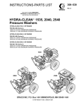
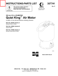
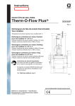
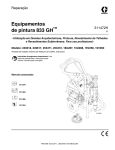
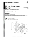
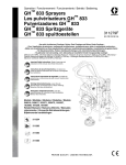
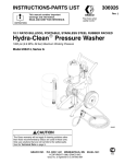
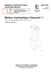
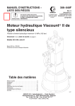
Instructions–Parts List
ViscountR II
Hydraulic Motor
307158ZAF
EN
Reciprocating hydraulic motor for use with Graco high performance
coating pumps.
Important Safety Instructions
Read all warnings and instructions in this manual.
Save these instructions.
Model 235345
See page 2 for model information, including
maximum hydraulic fluid input pressure.
04471
Table of Contents
Warnings . . . . . . . . . . . . . . . . . . . . . . . . . . . . . 3
Installation . . . . . . . . . . . . . . . . . . . . . . . . . . . . 6
Service . . . . . . . . . . . . . . . . . . . . . . . . . . . . . . 8
Parts List & Drawings
Model 217022 . . . . . . . . . . . . . . . . . . . . . . 14
Model 217338 . . . . . . . . . . . . . . . . . . . . . . 16
Model 235345 . . . . . . . . . . . . . . . . . . . . . . 18
Model 262818 and 24W139 . . . . . . . . . . 20
Mounting Hole Layout . . . . . . . . . . . . . . . . . 22
Dimensions . . . . . . . . . . . . . . . . . . . . . . . . . . 22
Technical Data . . . . . . . . . . . . . . . . . . . . . . . 23
Warranty . . . . . . . . . . . . . . . . . . . . . . . . . . . . 24
Graco Information . . . . . . . . . . . . . . . . . . . . 24
Models
Model
Series
Maximum Hydraulic
Fluid Input Pressure
Description
217022
D
1500 psi (10 MPa, 103 bar)
Replacement motor for GH533, GH733,
and GH833 Sprayers
217338
E
1500 psi (10 MPa, 103 bar)
Replacement motor for ViscountR II
Plural Component Pump
235345
A
1500 psi (10 MPa, 103 bar)
ViscountR II Motor, Interchanges with
KingR Air Motor
262818
A
1800 psi (12 MPa, 124 bar)
Replacement motor for XP and Xtreme
Sprayer, Interchanges with NXT 6500
NXT Air Motor and 8 in. tie rod diameter
lowers
24W139
A
1900 psi (13.1 MPa, 131 bar)
Hydraulic motor for Hydra–CleanR
Sprayers, Interchanges with NXT 6500
NXT Air Motor and 8 in. tie rod diameter
lowers
2
307158
Warnings
Warning Symbol
Caution Symbol
WARNING
CAUTION
This symbol alerts you to the possibility of serious
injury or death if you do not follow the instructions.
This symbol alerts you to the possibility of damage to
or destruction of equipment if you do not follow the
corresponding instructions.
WARNING
EQUIPMENT MISUSE HAZARD
Equipment misuse can cause the equipment to rupture or malfunction and result in serious injury.
INSTRUCTIONS
D This equipment is for professional use only.
D Read all instruction manuals, tags, and labels before operating the equipment.
D Use the equipment only for its intended purpose. If you are uncertain about usage, call your Graco
distributor.
D Do not alter or modify this equipment. Use only genuine Graco parts and accessories.
D Check equipment daily. Repair or replace worn or damaged parts immediately.
D Do not exceed the maximum working pressure stated on the equipment or in the Technical Data
for your equipment. Do not exceed the maximum working pressure of the lowest rated component
in your system.
D Use fluids and solvents which are compatible with the equipment wetted parts. Refer to the Technical Data section of all equipment manuals. Read the fluid and solvent manufacturer’s warnings.
D Handle hoses carefully. Do not pull on hoses to move equipment.
D Route hoses away from traffic areas, sharp edges, moving parts, and hot surfaces. Do not expose
Graco hoses to temperatures above 82_C (180_F) or below –40_C (–40_F).
D Do not move or lift pressurized equipment.
D Wear hearing protection when operating this equipment.
D Comply with all applicable local, state, and national fire, electrical, and safety regulations.
307158
3
WARNING
SKIN INJECTION HAZARD
Spray from the gun, hose leaks or ruptured components can inject fluid into your body and cause
extremely serious injury, including the need for amputation. Fluid splashed in the eyes or on the skin
can also cause serious injury.
D Fluid injected into the skin might look like just a cut, but it is a serious injury. Get immediate surgical treatment.
D Do not point the gun at anyone or at any part of the body.
D Do not put your hand or fingers over the spray tip.
D Do not stop or deflect leaks with your hand, body, glove or rag.
D Do not “blow back” fluid; this is not an air spray system.
D Always have the tip guard and the trigger guard on the gun when spraying.
D Check the gun diffuser operation weekly. Refer to the gun manual.
D Be sure the gun trigger safety operates before spraying.
D Lock the gun trigger safety when you stop spraying.
D Follow the Pressure Relief Procedure on page 8 if the spray tip clogs and before cleaning,
checking or servicing the equipment.
D Tighten all fluid connections before operating the equipment.
D Check the hoses, tubes, and couplings daily. Replace worn, damaged, or loose parts immediately.
Permanently coupled hoses cannot be repaired; replace the entire hose.
D Use only Graco approved hoses. Do not remove any spring guard that is used to help protect the
hose from rupture caused by kinks or bends near the couplings.
MOVING PARTS HAZARD
Moving parts can pinch or amputate your fingers.
D Keep clear of all moving parts when starting or operating the pump.
D Before servicing the equipment, follow the Pressure Relief Procedure on page 8 to prevent the
equipment from starting unexpectedly.
4
307158
WARNING
FIRE AND EXPLOSION HAZARD
Improper grounding, poor ventilation, open flames or sparks can cause a hazardous condition and
result in a fire or explosion and serious injury.
D Ground the equipment and the object being sprayed. Refer to Grounding on page 7.
D If there is any static sparking or you feel an electric shock while using this equipment, stop spraying immediately. Do not use the equipment until you identify and correct the problem.
D Provide fresh air ventilation to avoid the buildup of flammable fumes from solvents or the fluid
being sprayed.
D Keep the spray area free of debris, including solvent, rags, and gasoline.
D Before operating this equipment, electrically disconnect all equipment in the spray area.
D Before operating this equipment, extinguish all open flames or pilot lights in the spray area.
D Do not smoke in the spray area.
D Do not turn on or off any light switch in the spray area while spraying or while there are any fumes
in the air.
D Do not operate a gasoline engine in the spray area.
TOXIC FLUID HAZARD
Hazardous fluid or toxic fumes can cause serious injury or death if splashed in the eyes or on the skin,
inhaled, or swallowed.
D Know the specific hazards of the fluid you are using.
D Store hazardous fluid in an approved container. Dispose of hazardous fluid according to all local,
state and national guidelines.
D Always wear protective eyewear, gloves, clothing and respirator as recommended by the fluid and
solvent manufacturer.
307158
5
Installation
WARNING
CAUTION
The maximum safe hydraulic input pressure to this
motor depends on the lower displacement pump to
which it is connected.
Recommended Hydraulic Oil
Use Graco-approved Hydraulic Oil, Part No. 169236
(5 gal) or 207428 (1 gal)) or a premium, ISO grade
46 petroleum-based hydraulic oil containing rust and
oxidation inhibitors and anti-wear agents.
With Graco Displacement Pump Models 207474,
207655, 210208, 217527, 217339, 222796,
222801, 222803, 222805, 222810, and 222811
use a maximum of 1500 psi (10 MPa, 103 bar)
hydraulic input pressure.
Before using any other type of oil in this motor,
contact your Graco distributor. Unauthorized use of
lesser grade oil or substitutes may void the warranty.
Maximum Hydraulic Input Pressure
For Graco Displacement Pump Models 24B923
and 687055, usa a maximum of 1900 psi (13.1
MPa, 131 bar) hydraulic input pressure.
Never exceed 1000 psi (7 MPa, 70 bar) hydraulic
input pressure with the motor connected to any
displacement pump other than those listed above;
serious injury or damage to the equipment may
result.
WARNING
To reduce the risk of serious injury whenever you
are instructed to relieve pressure, always follow the
Pressure Relief Procedure on page 8.
Be sure you always shut off the supply line shutoff
valve (E) first, and then the return line shutoff
valve. This is to prevent overpressurizing the motor
or its seals. When starting up the hydraulic system,
open the return line shutoff valve first.
CAUTION
Hydraulic Oil Working Temperature
Models 217022 and 217338
The recommended hydraulic oil operating temperature is 80 – 115_F (27 – 45_C). The motor seals will
wear faster and leakage may occur if the pump is
operated at higher oil temperatures.
If the hydraulic oil temperature approaches 130_F
(54_C), check the hydraulic fluid supply cooling
system, filters, etc. and clean or repair as needed.
Models 235435, 262818, and 24W139
The recommended hydraulic oil operating temperature is 80 – 160_F (27 – 71_C). The motor seals will
wear faster and leakage may occur if the pump is
operated at higher oil temperatures.
If the hydraulic oil temperature approaches 180_F
(82_C), check the hydraulic fluid supply cooling
system, filters, etc. and clean or repair as needed.
Refer to the complete pump manual for detailed installation information or contact your Graco distributor.
NOTE: A 1 in. npt seal (57) is supplied in a plastic bag
with the motor. Thread the seal onto the threads of
your hydraulic return line fitting (A). Thread the fitting
into the upper housing (40) and torque as needed.
Then tighten the seal (57) against the motor to provide
a secure seal. See Fig. 1.
Keep the hydraulic system clean
To reduce the risk of damaging the hydraulic power
supply, blow out all hydraulic lines with air, flush
thoroughly with solvent, and then blow out with air
again before connecting the lines to the motor.
40
A
Always plug the hydraulic inlets, outlets and lines
when disconnecting them to avoid introducing dirt
and other contaminants into the system.
Carefully follow the manufacturer’s recommendations
on reservoir and filter cleaning, and periodic changes
of hydraulic fluid.
6
307158
Fig. 1
57
04467
Installation
Grounding
WARNING
For your safety, read the FIRE AND EXPLOSION
HAZARD WARNINGS on page 5, and ground
your entire system as instructed below. This section also includes details on how to connect the
grounding wire and clamp to the various hydraulic
motors.
Proper grounding is an essential part of maintaining a
safe system.
To reduce the risk of static sparking, ground the pump.
Check your local electrical code for detailed grounding
instructions for your area and type of equipment. Be
sure to ground all of this equipment:
1. Pump: use a ground wire and clamp as shown to
the right.
7. Any pails used when flushing: Use only metal,
grounded pails when flushing. Make firm metal-tometal contact between the metal part of the spray
gun and the pail. Use the lowest possible pressure.
8. To maintain grounding continuity when flushing or
relieving pressure, always hold a metal part of the
gun firmly to the side of a grounded metal pail, and
then trigger the spray gun.
Models 217338, 235345, 262818, and 24W139
Loosen the locknut (A) of the grounding lug and washer. Insert one end of the wire (B) in the grounding lug
(61) and tighten the locknut securely. See Fig. 2.
Connect the other end of the wire to a true earth
ground, as recommended by your local code. Order
Part No. 237569, Ground Wire and Clamp.
Model 217022
The ground wire and clamp are supplied with your GH
Sprayer. Connect the clamp to a true earth ground as
recommended by your local code.
2. Hydraulic hoses and fluid outlet hoses: use only
electrically conductive hoses.
B
3. Hydraulic power supply and air compressor:
follow manufacturer’s recommendations.
4. Spray gun: obtain grounding through connection to
a properly grounded fluid hose and pump.
5. Fluid supply container: according to local code.
6. Object being sprayed: according to local code.
A
Fig. 2
61
04468
307158
7
Service
Pressure Relief Procedure
WARNING
SKIN INJECTION HAZARD
The system pressure must be manually
relieved to prevent the system from
starting or spraying accidentally. Fluid
under high pressure can be injected through the
skin and cause serious injury. To reduce the risk of
an injury from injection, splashing fluid, or moving
parts, follow the Pressure Relief Procedure
whenever you:
D
D
D
D
are instructed to relieve the pressure,
stop spraying,
check or service any of the system equipment,
or install or clean the spray tip.
Before you start:
Be sure you have all necessary parts on hand.
1. Repair Kit 220457 is available for Models 217022
and 217338.
Repair Kit 223654 is available for Models 235345,
262818, and 24W139.
2. The repair kits must be purchased separately. An
asterisk behind a reference number in the parts
list, for example (25*), indicates that the part is
included in the repair kit.
3. Clean all parts as you disassemble them and
inspect them for wear or damage. Replace parts
as necessary.
Disassembly (Refer to Fig. 3)
1. Lock the gun trigger safety.
2. Shut off the hydraulic power supply.
3. Close the supply line shutoff valve, and then the
return line shutoff valve.
4. Unlock the gun trigger safety.
5. Hold a metal part of the gun firmly to the side of a
grounded metal pail, and trigger the gun to relieve
pressure.
NOTE: Use all the replacement parts that are in the
repair kit.
1. Flush the displacement pump if possible.
WARNING
To reduce the risk of serious injury whenever you
are instructed to relieve pressure, always follow the
Pressure Relief Procedure on page 8.
6. Lock the gun trigger safety.
2. Relieve the pressure.
7. Open the drain valve (required in your system),
having a container ready to catch the drainage.
3. Stop the pump at the bottom of its stroke.
8. Leave the drain valve open until you are ready to
spray again.
If you suspect that the spray tip or hose is completely
clogged, or that pressure has not been fully relieved
after following the steps above, very slowly loosen the
tip guard retaining nut or hose end coupling and relieve
pressure gradually, then loosen completely. Now clear
the obstruction.
8
307158
CAUTION
Avoid getting dust or dirt in the motor during service.
Cleanliness is essential when repairing an hydraulic
motor.
4. Disconnect the displacement pump hoses. Disconnect the hydraulic hoses and plug all hydraulic
connections and lines to prevent contamination.
Service
Disassembly (continued – refer to Fig. 3)
CAUTION
When removing the displacement pump, hold it
securely. The pump is heavy and could fall off the
motor.
5. Disconnect the displacement pump from the
motor, as explained in your separate pump manual.
6. Place the hydraulic motor in a bench vise.
7. Push or lightly tap the piston (49) up as far as
possible.
NOTE: The tie rod nuts (3), socket screws (8), cap–
screws (24), and retainer (32) are fastened with Loctiter TL–242. Heat may be used sparingly to soften
adhesive sealant during disassembly.
8. For Models 217022, 217338, 262818, and
24W139, loosen, but do not remove, the four tie
rod nuts (3) and the nuts (B) on the hydraulic tube
(48).
For Model 235345, you need to remove the cap
screws (21), the drip pan (26), the drip cover (31),
and machine screw (42) before loosening the tie
rod nuts. Then remove the four tie rod nuts (3).
Loosen the nuts (B) on the hydraulic tube (48) and
loosen the tie rods (35).
9. Remove the motor from the vise and lay it in a
pan.
10. Remove one detent assembly: retaining plug (28),
o-ring (25), spring (29), ball guide (27) and ball (7).
If the ball or other parts stick in the upper housing
(40), turn the motor over and tap lightly. Do not
allow the parts to fall into the motor. Repeat the
procedure for the other detent assembly.
11. Remove the tie rods (35), but do not remove the
crown nuts (22).
12. Remove the socket screws (8) and the end cap
(44). Pull the stop plug (43) from the upper housing (40).
13. Unscrew the top and bottom compression nuts (B)
on the hydraulic tube (48). Rotate the upper housing (40) and remove the tube, being careful not to
damage the flare (A). Allow the oil to drain from
the motor into the pan.
CAUTION
With the tie rods removed, the assembly may separate at the joints between the cylinder (39) and the
upper and lower housings (40 and 41).
14. Rock the upper housing (40) to work it free and lift
it about 3 inches off the cylinder (39). The cylinder can stay in the lower housing (41).
15. Hold the trip rod (36) with an adjustable wrench on
the flats of the rod, and remove the top hex nut
(20) from the trip rod.
16. Remove the upper housing (40).
17. Remove the trip rod guides (34), compression
springs (38) and valve spool (37) from the upper
housing. Inspect the bearing inside of the guide
(51) in place. If bearing is damaged replace item
51.
NOTE: Inspect the trip rod (36) above the shoulder for
damage. There must be no reduction in diameter.
Replace if necessary.
18. Pull the trip rod and piston from the lower housing
(41) and cylinder (39). Place the piston flats (49) in
a vise; tighten the vise on the flats of the piston.
Use a face spanner to remove the retainer (32).
Remove the trip rod (36) from the piston (49).
19. Remove the trip rod locknut (9) and piston stop
(33). If the piston is replaced, remove the spring
(55) to use in the new piston.
20. For Models 217022 and 217338, place the lower
housing (41) on top of vice jaws. Pinch the adapter
plate (14) in the jaws. Twist and remove. Inspect
the bearing (30) and wiper (18) for wear. Replace if
necessary.
21. Turn lower housing over and remove the seal (23)
and backup seal (23a).
22. For Models 235345, 262818, and 24W139, remove the bearing (45), packings (23), and o-ring
(12, Model 235345 only).
307158
9
Service
Model 217022 shown
13
8
44
43
22
1
40
11
35
39
7
27
29
25
28
54
57
13
17
56
B
48
A
20
34
38
23
36
37
B
A
A
41
56
23a
16
38
34
12
32
30
33
9
51
14
24
19
18
55
10
49
3
NOTE: Circled letters refer to connected points.
Fig. 3
10
307158
04464
Service
Reassembly (Refer to Fig. 4)
NOTE: Model 217022 uses one seal (23) and a backup seal (23a).
1. Lubricate the seal(s) (23) with hydraulic oil. Install
them in the lower housing (41) with the lips facing
up toward the top of the motor.
2. For Models 217022 and 217338, install the o-ring
(12*) onto the adapter (14). Install the adapter (14)
into the lower housing (41), making sure it seats
properly. For Model 235345, install the o-ring (12)
onto the lower housing (41).
3. Place the piston flats in a vise. Install the spring
(55) inside the piston (49). The compression rings
(19) must be positioned with the joints about 180_
opposed. Be sure the o-ring (26) is in place on
Model 235345.
4. Install the piston stop (33) and locknut (9) on the
trip rod. Torque the nut to 117–123 in-lb (13.2–13.9
N.m). Slide the trip rod (36) into the piston (49).
Apply thread sealant to the retainer (32) threads.
With the piston flats in a vise, tighten the retainer
until it is flush or below the piston surface. This is
important to prevent the retainer from backing out
during operation and damaging the motor.
NOTE: For Models 235345, 262818, and 24W139, set
base (2) on workbench during reassembly. For Models
217022 and 217338, place adapter (14) in vise jaws
and lower housing (41) on top of jaws.
5. Install the o-ring (13) onto the cylinder (39). Install
the cylinder (39) into the lower housing (41).
6. Install the trip rod and piston into the cylinder (39)
and lower housing (41) so the piston is recessed at
least 1 inch (25 mm) from the top of the cylinder.
7. If the bearing and guide (51) was removed, install
it on the upper housing (40) with the three screws
(24) (apply thread sealant).
8. Hold the flats of the trip rod with an adjustable
wrench and install the upper housing (40). The trip
rod will protrude from the top.
9. Slide the lower trip rod guide (34) and spring (38)
onto the trip rod. Install the spool (37) with the
detent at the top. Install the top spring (38) and
guide (34) on the trip rod. Install the top hex nut
(20). Torque the nut to 82–88 in-lb (9.3–9.9 N.m).
10. Remove the adjustable wrench. Seat the upper
housing (40) onto the cylinder (39), so the tube
fittings align with those on the lower housing.
Reinstall the hydraulic tube (48) and loosely
tighten the compression nuts. See the Parts
Drawing for your motor.
11. Replace the o-ring (11) on the stop plug (43). Seat
the plug into the upper housing (40).
12. Install the end cap (44), using thread sealant on
the socket screws (8).
13. Lubricate the threads of the tie rods (35) and install
them with lockwashers (1). If the crown nuts (22)
were removed, reinstall them and torque them
onto the rods to 70–80 ft-lb (95–108 N.m).
14. For Models 217022, 217338, 262818, and
24W139, take the motor out of the vise jaws and
lay it on its side. Install the lower plate (10).
NOTE: For Model 217022, align the point of adapter
plate (10) in the same direction as the fluid tube (16).
15. For Models 217022, 217338 and 262818, apply
thread sealant to the lower threads of the tie rods
(35) and torque the tie rod nuts (3) to 70–80 ft-lb
(95–108 N.m).
For Model 235345 and 24W139, torque tie rods
into base, apply thread sealant, then torque the tie
rod nuts (3) to 70–80 ft–lb (95–108 N.m).
16. With the motor on its side, install one detent
assembly: the ball (7), guide (27) with the concave
surface toward the ball, spring (29), o-ring (25*)
and retaining plug (28). Torque the plug to
152–158 in-lb (17.2–17.9 N.m). Repeat for the
other side of the motor.
17. For Model 235345, slide the drip cover (31) onto
the piston (49) up to the o-ring (30). Install screw
(42) into the piston. Attach the drip pan (26) to the
base using screws (21).
18. Snugly tighten the compression nuts on the hydraulic tube (48) and torque to 60–80 ft-lb (81–108
N.m).
19. Install the motor on the displacement pump. Reconnect all fluid lines. Be sure the ground wire is
connected before operating the pump.
307158
11
Service
44
8
10
7
34
6
29
25
28
20
8
27
9
38
40
37
10
24
1
Rings must be positioned
with joints opposed
2
Lips must face
up toward top of motor
3
Model 235345 use only one
seal (23)
4
Torque to
70–80 ft-lb (95–108 N.m)
5
Apply thread lubricant to
lower threads
Concave surface faces ball
34
51
36
5
35
33
13
32
10
6
19
1
7
8
9
7
9
13
10
41
Torque to
117–123 in-lb (13.2–13.9 N.m)
Torque to
82–88 in-lb (9.3–9.9 N.m)
Torque to
152–158 in-lb (17.2–17.9 N.m)
Apply LoctiteR TL–242
Thread Sealant
55
23
2
3
12
30
3
4
10
04487
Fig. 4
12
307158
Notes
307158
13
Parts
Model 217022, Series D
13*
8
44
43
22
1
40
*11
35
39
7*
27*
29*
25*
28*
54
57
*13
17
41
56
56
48
A
20
34
38*
23
23a
36*
*37
A
16
*38
34
12*
32
30
33*
9
51
14
24
*19
18
55
10
49
3
NOTE: See the service section for important
torque and lubrication information.
NOTE: Circled letters refer to connected points.
14
307158
04464
Parts
Model 217022, Series D
Includes items 1–57
Ref.
No.
Part No.
Description
1
3
7*
8
100128
102087
101701
101864
9
10
11*
12*
13*
14
16
17
103450
609821
104093
104280
104095
609820
104098
104099
18
19*
20
22
23
23a
104102
104103
104105
104143
112130
112762
24
108538
25*
27*
28*
150111
167210
167431
LOCKWASHER, spring, 5/8 in.
4
NUT, hex jam, 5/8–18
4
BALL, 1/4 in. dia.
2
CAPSCREW, soc hd,
5/16–18 x 1 in.
3
NUT, hex, self-locking, 5/16–18
1
PLATE, tie
1
O-RING, nitrile rubber
1
O-RING, nitrile rubber
1
O-RING, nitrile rubber
2
ADAPTER, plate
1
TEE, tube, for 3/4 in. (19 mm) tube1
ELBOW, 90_, for
3/4 in. (19 mm) tube
1
WIPER
1
RING, piston, compression
2
NUT, hex lock, 1/4–20
1
NUT, crown, 5/8–18
4
SEAL, v-block, polyurethane
1
SEAL, backup, modular,
molythane
1
SCREW, soc flat hd, self-locking,
1/4–20 x 1/2 in.
3
GASKET, plug
2
GUIDE, ball
2
PLUG, spring retaining
2
Qty.
Ref.
No.
Part No.
Description
29*
30
32
33*
34
35
36*
37*
38*
39
40
41
43
44
48
49
51
54
55
56
57
108522
171395
171398
181243
183659
177931
171407
181874
171411
171412
172814
171414
183252
183290
210108
188086
210292
101754
104664
105429
105430
SPRING, helical compression
BEARING, sleeve
RETAINER
STOP, piston
GUIDE, trip rod
ROD, tie
ROD, trip
SPOOL, valve
SPRING, compression
CYLINDER
HOUSING, upper
HOUSING, lower
PLUG, stop
CAP, end
TUBE
PISTON
BEARING and GUIDE
PLUG, pipe, soc hd, 3/8 npt
SPRING, compression
NUT, seal, 3/4 npt
NUT, seal, 1 in. npt
2
1
1
1
2
4
1
1
2
1
1
1
1
1
1
1
1
1
1
2
supplied in a plastic bag
1
*
Qty.
These parts are also included in Repair Kit 220457,
which may be purchased separately.
307158
15
Parts
Model 217338, Series E
13*
8
44
43
35
22
*11
39
1
40
54
57
7*
27*
29*
25*
28*
*13
17
56
A
20
56
34
38*
48
41
23
36*
*37
16
12*
A
*38
34
51
32
33*
9
30
14
24
*19
18
55
10
49
61, 62
NOTE: See the service section for important
torque and lubrication information.
3
NOTE: Circled letters refer to connected points.
04465
16
307158
Parts
Model 217338, Series E
Includes items 1–62
Ref.
No.
Part No.
Description
1
3
7*
8
100128
100155
101701
101864
9
10
11*
12*
13*
14
16
17
103450
181889
104093
104280
104095
609820
104098
104099
18
19*
20
22
23
24
104102
104103
104105
104143
104203
108538
LOCKWASHER, spring, 5/8 in.
4
NUT, hex jam, 5/8–18
4
BALL, 1/4 in. dia.
2
CAPSCREW, soc hd,
5/16–18 x 1 in.
3
NUT, hex, self-locking, 5/16–18
1
PLATE, tie
1
O-RING, nitrile rubber
1
O-RING, nitrile rubber
1
O-RING, nitrile rubber
2
ADAPTER, plate
1
TEE, tube, for 3/4 in. (19 mm) tube1
ELBOW, 90_, for 3/4 in.
(19 mm) tube
1
WIPER
1
RING, piston, compression
2
NUT, hex lock, 1/4–20
1
NUT, crown, 5/8–18
4
SEAL, v-block, polyurethane
2
SCREW, soc flat hd, self locking,
1/4–20 x 1/2 in.
3
GASKET, plug
2
GUIDE, ball
2
PLUG, spring retaining
2
SPRING, helical compression
2
BEARING, sleeve
1
25*
27*
28*
29*
30
150111
167210
167431
108522
171395
Qty.
Ref.
No.
Part No.
Description
32
33*
34
35
36*
37*
38*
39
40
41
43
44
48
49
51
54
55
56
57
171398
181243
183659
171405
171407
181874
171411
171412
172814
171414
171416
180953
210108
188086
210292
101754
104664
105429
105430
61
62
104029
104582
RETAINER
STOP, piston
GUIDE, trip rod
ROD, tie
ROD, trip
SPOOL, valve
SPRING, compression
CYLINDER
HOUSING, upper
HOUSING, lower
PLUG, stop
CAP, end
TUBE
PISTON
BEARING and GUIDE
PLUG, pipe, soc hd, 3/8 npt
SPRING, compression
NUT, seal, 3/4 npt
NUT, seal, 1 in. npt
supplied in a plastic bag
GROUNDING LUG
WASHER
*
Qty.
1
1
2
4
1
1
2
1
1
1
1
1
1
1
1
1
1
1
1
1
1
These parts are also included in Repair Kit 220457,
which may be purchased separately.
307158
17
Parts
Model 235345, Series A
53
8
44
43
22
1
*11
50a
50
13*
35
40
47
47a
7 27
B
14a
B
52
29
39
13*
25
28
23*
47
14
57
47a
6
20
10a
34
38*
10
48
41
A
36
45*
37
*38
5
32
34
A
5a
23*
33
12*
9
51
Y16
24
4
*19
55
61
62
18Y
Y2
3
49
42
31
46
26
*30
21
NOTE: See the service section for important
torque and lubrication information.
NOTE: Circled letters refer to connected points.
04466
18
307158
Parts
Model 235345, Series A
Ref.
No.
Part No.
Description
1
2Y
3
4
5
100128
290331
100155
186221
110797
LOCKWASHER, spring, 5/8 in.
LABEL, instruction, English
NUT, hex jam, 5/8–18
BASE
ELBOW, male, 3/4 npt
4
1
4
1
Includes item 5a
5a
6
110926
112574
1
1
7
8
101701
101864
.O-RING, nitrile rubber
ADAPTER, 3/4 npt (f) x
1–1/16–12
BALL, 1/4 in. dia.
CAPSCREW, soc hd,
5/16–18 x 1 in.
NUT, hex, self-locking, 5/16–18
TEE, 7/8–14 unf–2a x 1 1/16–
12un–2a, 37_ flare for 3/4 in. dia.
tube, Includes item 10a
.O-RING, nitrile rubber
O-RING, nitrile rubber
O-RING, buna–N
O-RING, nitrile rubber
ADAPTER, 1 –11-1/2 npt x
1 5/16–12un–2a, Includes item 14a
.O-RING, nitrile rubber
LABEL, identification not shown
LABEL, warning
SCREW, type “u” drive,
No. 4 x 0.188 in.
PLATE, warning
RING, piston, compression
NUT, hex lock, 1/4–20
SCREW, cap, hex hd;
1/4–20 x .0.5 in.
NUT, crown, 5/8–18
SEAL, u-cup, polyurethane
SCREW, soc flat hd, self locking,
1/4–20 x 1/2 in.
O-RING, nitrile rubber
PAN, drip
GUIDE, ball
RETAINER, spring
SPRING, helical compression
O-RING, nitrile rubber
COVER, drip
RETAINER
9
10
103450
110791
10a
11*
12*
13*
14
110926
104093
110800
166071
110876
14a
15
16Y
17
110927
177756
172975
100508
18Y
19*
20
21
172815
104103
104105
100333
22
23*
24
104143
110795
108538
25
26
27
28
29*
30*
31
32
110801
210110
167210
186222
108522
165295
171397
171398
Ref.
No.
Part No.
Description
33
34
35
36
37
38*
39
40
41
42
181243
183659
171405
171407
181874
171411
186219
186217
186218
101577
3
1
43
44
45*
171416
180953
186223
1
46
103875
47
110792
47a
48
49
50
110801
210108
188087
110799
STOP, piston
GUIDE, trip rod
ROD, tie
ROD, trip
SPOOL, valve
SPRING, compression
CYLINDER
HOUSING, upper
HOUSING, lower
SCREW, machine, hex hd;
No. 10–20 x 0.375 in.
PLUG, stop
CAP, end
BEARING, piston,
bronze-filled PTFE
ADAPTER, barbed hose, 1/8
npt x 0.25 in. (6.4 mm) ID hose
ELBOW, 90_, 7/16–20 unf–2a(m)
x 9/16–18 unf–2a(m), 37_flare for
3/8 in. dia. tube, Includes item 47a
.O-RING, nitrile rubber
TUBE
PISTON
PLUG, 9/16–18 unf–2b,
50a
51
52
53
55
57
110925
210292
223608
108132
104664
105430
61
62
104029
104582
Qty.
1
2
1
1
1
2
1
1
1
1
4
1
2
1
3
4
2
3
2
1
2
2
2
1
1
1
Qty.
Includes item 50a
*
.O-RING, nitrile rubber
BEARING and GUIDE
TUBE, drain
RING, lift
SPRING, compression
NUT, seal, 1 in. npt
supplied in a plastic bag
GROUNDING LUG
WASHER
1
2
4
1
1
2
1
1
1
1
1
1
1
1
2
2
1
1
1
1
1
1
1
1
1
1
1
These parts are also included in Repair Kit 223654,
which may be purchased separately.
Y Replacement Danger and Warning labels, tags and
cards are available at no cost. Label 290331 is also
available in the following languages:
German (Part No. 290396)
French (Part No. 290397)
Spanish (Part No. 290398).
307158
19
Parts
Model 262818, Series A
Model 24W139, Series A
53
8
44
43
13*
B
22
1
*11
40
47
47a
7
14a
14
35
52
27
29
25
39
28
13*
47
50a
50
B
41
47a
A
20
34
57
38*
6
45*
36
37
5
48
A
38*
33
34
9
5a
23*
61
62
4
Model
262818
19*
51
24
3
32
ti19177a
49
*23
64
NOTE: See the service section for important
torque and lubrication information.
NOTE: Circled letters refer to connected points.
20
307158
4
Model
24W139
Model 262818, Series A
Model 24W139, Series A
Ref.
No.
Part No.
Description
LOCKWASHER, spring, 5/8 in.
NUT, hex jam, 5/8–18
PLATE, for Model 262818
PLATE, for Model 24W139
ELBOW, male, 3/4 npt
4
4
1
5
100128
100155
16M539
17B757
110797
Includes item 5a
5a
6
110926
112574
1
1
7
8
101701
101864
9
10
103450
110791
.O-RING, nitrile rubber
ADAPTER, 3/4 npt (f) x
1–1/16–12
BALL, 1/4 in. dia.
CAPSCREW, soc hd,
5/16–18 x 1 in.
NUT, hex, self-locking, 5/16–18
TEE, 7/8–14 unf–2a x 1 1/16–
12un–2a, 37_ flare for 3/4 in. dia.
tube, Includes item 10a
.O-RING, nitrile rubber
O-RING, nitrile rubber
O-RING, nitrile rubber
ADAPTER, 1 –11-1/2 npt x
1 5/16–12un–2a, Includes item 14a
.O-RING, nitrile rubber
LABEL, identification not shown
SCREW, type “u” drive,
No. 4 x 0.188 in.
RING, piston, compression
NUT, hex lock, 1/4–20
NUT, crown, 5/8–18
SEAL, u-cup, polyurethane
SCREW, soc flat hd, self locking,
1/4–20 x 1/2 in.
O-RING, nitrile rubber
GUIDE, ball
RETAINER, spring
SPRING, helical compression
RETAINER
STOP, piston
1
3
4
10a
11*
13*
14
110926
104093
166071
110876
14a
15
17
110927
177756
100508
19*
20
22
23*
24
104103
104105
104143
110795
108538
25
27
28
29*
32
33
110801
167210
186222
108522
171398
181243
Qty.
1
2
3
1
1
1
1
2
Ref.
No.
Part No.
Description
34
35
36
37
38*
39
40
41
43
44
45*
183659
171405
171407
181874
171411
186219
186217
186218
171416
180953
186223
47
110792
47a
48
49
50
110801
210108
16M538
110799
GUIDE, trip rod
ROD, tie
ROD, trip
SPOOL, valve
SPRING, compression
CYLINDER
HOUSING, upper
HOUSING, lower
PLUG, stop
CAP, end
BEARING, piston,
bronze-filled PTFE
ELBOW, 90_, 7/16–20 unf–2a(m)
x 9/16–18 unf–2a(m), 37_flare for
3/8 in. dia. tube, Includes item 47a
.O-RING, nitrile rubber
TUBE
PISTON
PLUG, 9/16–18 unf–2b,
50a
51
52
53
55
57
110925
210292
223608
108132
104664
105430
61
62
64
104029
104582
16M653
Qty.
Includes item 50a
1
1
1
4
2
1
4
2
3
2
2
2
2
1
1
*
.O-RING, nitrile rubber
BEARING and GUIDE
TUBE, drain
RING, lift
SPRING, compression
NUT, seal, 1 in. npt
supplied in a plastic bag
GROUNDING LUG
WASHER
ADAPTER, hydraulic motor,
Xtreme, 7/8–14 unf–2A x
3/4–16 unf–2B
2
4
1
1
2
1
1
1
1
1
1
2
2
1
1
1
1
1
1
1
1
1
1
1
1
These parts are also included in Repair Kit 223654,
which may be purchased separately.
307158
21
Mounting Hole
Layout
Model 217022
Model 217022
A
7.2 in
C
(182.8 mm)
3.5 in.
(88.9 mm)
B
8.1 in.
D
(205.7 mm)
0.641 in.
(16.3 mm)
Model 217338
B
C
C
A
E
0.438 in.
(11.1 mm)
F
7.42 in.
(188.4 mm)
G
11.28 in.
(286.5 mm)
K
11.31 in.
(287.2 mm)
Model 235345
D
04469
Model 217338
H
0.438 in.
(11.1 mm)
J
7.42 in.
(188.4 mm)
Models 262818 and 24W139
G
F
L
3/8–16 in.
M
6.186 in.
(157.1 mm)
N
11.25 in.
(285.7 mm)
Dimensions
E
04470
Model 235345
Models 217022, 217338, 24W139
and 262818 (shown)
1 in. npt Outlet
J
K
3/4 in. npt Inlet
H
19.3 in.
(490 mm)
04508
Model 262818 and 24W139
04489
M
N
NOTE: Height for Model 235345 is 25.4 in.
(645.16 mm).
L
ti19178a
22
307158
NOTE: Model 24W139 has a 3/4 in. #12 JIC pump
inlet.
Technical Data
Viscount Hydraulic Motor
US
Metric
Models 217022, 217338, 235345.
1500 psi
10 MPa, 103 bar
Model 262818
1800 psi
12 MPa, 124 bar
Model 24W139
1900 psi
13.1 MPa, 131 bar
Maximum hydraulic fluid flow
12 gpm
45.6 liter/min
Hydraulic fluid consumption
1 gal. per 5 cycles
3.8 liter per 5 cycles
Effective piston area
4.9 sq. in.
31.6 cm2
Piston rod diameter
2.5 in.
64 mm
Stroke length
4.69 in.
119.1 mm
Thrust at 1500 psi (10 MPa, 103
bar)
7300 psi
32 472 N
approximately 96 lb.
43.5 kg
Maximum hydraulic fluid input pressure
Also see the WARNING on page 6.
Weight
Loctiter is a registered trademark of the Loctite Corp.
307158
23
Graco Standard Warranty
Graco warrants all equipment listed in this manual which is manufactured by Graco and bearing its name to be free from defects in
material and workmanship on the date of sale by an authorized Graco distributor to the original purchaser for use. With the exception of
any special extended or limited warranty published by Graco, Graco will, for a period of twelve months from the date of sale, repair or
replace any part of the equipment determined by Graco to be defective. This warranty applies only when the equipment is installed,
operated and maintained in accordance with Graco’s written recommendations.
This warranty does not cover, and Graco shall not be liable for general wear and tear, or any malfunction, damage or wear caused by
faulty installation, misapplication, abrasion, corrosion, inadequate or improper maintenance, negligence, accident, tampering, or
substitution of non-Graco component parts. Nor shall Graco be liable for malfunction, damage or wear caused by the incompatibility of
Graco equipment with structures, accessories, equipment or materials not supplied by Graco, or the improper design, manufacture,
installation, operation or maintenance or structures, accessories, equipment or materials not supplied by Graco.
This warranty is conditioned upon the prepaid return of the equipment claimed to be defective to an authorized Graco distributor for
verification of the claimed defect. If the claimed defect is verified, Graco will repair or replace free of charge any defective parts. The
equipment will be returned to the original purchaser transportation prepaid. If inspection of the equipment does not disclose any defect
in material or workmanship, repairs will be made at a reasonable charge, which charges may include the costs of parts, labor, and
transportation.
Graco’s sole obligation and buyer’s sole remedy for any breach of warranty shall be as set forth above. The buyer agrees that no other
remedy (including, but not limited to, incidental or consequential damages for lost profits, lost sales, injury to person or property, or any
other incidental or consequential loss) shall be available. Any action for breach of warranty must be brought within two (2) years of the
date of sale.
GRACO MAKES NO WARRANTY, AND DISCLAIMS ALL IMPLIED WARRANTIES OF MERCHANTABILITY AND FITNESS FOR
A PARTICULAR PURPOSE IN CONNECTION WITH ACCESSORIES, EQUIPMENT, MATERIALS OR COMPONENTS SOLD BUT
NOT MANUFACTURED BY GRACO. These items sold, but not manufactured by Graco (such as electric motors, gas engines,
switches, hose, etc.), are subject to the warranty, if any, of their manufacturer. Graco will provide purchaser with reasonable assistance
in making any claim for breach of these warranties.
In no event will Graco be liable for indirect, incidental, special or consequential damages resulting from Graco supplying equipment
hereunder, or the furnishing, performance, or use of any products or other goods sold hereto, whether due to a breach of contract,
breach of warranty, the negligence of Graco, or otherwise.
FOR GRACO CANADA CUSTOMERS
The parties acknowledge that they have required that the present document, as well as all documents, notices and legal proceedings
entered into, given or instituted pursuant hereto or relating directly or indirectly hereto, be drawn up in English. Les parties
reconnaissent avoir convenu que la rédaction du présente document sera en Anglais, ainsi que tous documents, avis et procédures
judiciaires exécutés, donnés ou intentés à la suite de ou en rapport, directement ou indirectement, avec les procédures concernées.
Graco Information
TO PLACE AN ORDER, contact your Graco distributor, or call one of the following numbers
to identify the distributor closest to you:
1–800–328–0211 Toll Free
612–623–6921
612–378–3505 Fax
All written and visual data contained in this document reflects the latest product information available at the time of publication.
Graco reserves the right to make changes at any time without notice.
For patent information, see www.graco.com/patents.
Original instructions. This manual contains English. MM 307158
Graco Headquarters: Minneapolis
International Offices: Belgium, China, Japan, Korea
GRACO INC. AND SUBSIDIARIES S P.O. BOX 1441 S MINNEAPOLIS MN 55440–1441 S USA
Copyright 1974, Graco Inc. All Graco manufacturing locations are registered to ISO 9001.
www.graco.com
Revision ZAF, December 2014
24
307158