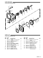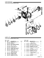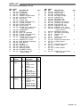
1
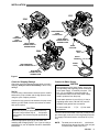
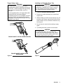
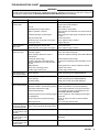
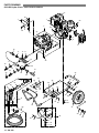
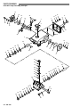
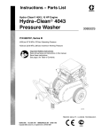
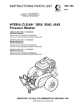
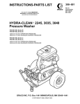
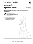
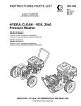
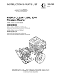
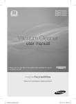
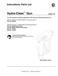
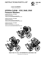
INSTRUCTIONS-PARTS LIST
308–530
Rev A
This manual contains IMPORTANT
WARNINGS and INSTRUCTIONS READ
AND RETAIN FOR REFERENCE
HYDRA-CLEAN 1535, 2040, 2540
Pressure Washers
HYDRA-CLEAN 1535, 5 HP ENGINE
P/N 800–698, Series A
1500 psi (103 bar) OPERATING PRESSURE
1900 psi (131 bar) MAXIMUM WORKING PRESSURE
HYDRA-CLEAN 2040, 8 HP ENGINE
P/N 800–699, Series A
2000 psi (138 bar) OPERATING PRESSURE
2400 psi (165 bar) MAXIMUM WORKING PRESSURE
HYDRA-CLEAN 2540, 9 HP ENGINE
P/N 800–700, Series A
2500 psi (172 bar) OPERATING PRESSURE
3000 psi (207 bar) MAXIMUM WORKING PRESSURE
1535
2040
2540
GRACO INC. P.O. Box 1441 MINNEAPOLIS, MN 55440–1441
COPYRIGHT 1991, GRACO INC.
INDEX
Warnings . . . . . . . . . . . . . . . . . . . . . . . . . . . . . . . . . . . . . . . . . . . . . . . . . . . . . . . 3
Installation . . . . . . . . . . . . . . . . . . . . . . . . . . . . . . . . . . . . . . . . . . . . . . . . . . . . . 5
Startup . . . . . . . . . . . . . . . . . . . . . . . . . . . . . . . . . . . . . . . . . . . . . . . . . . . . . . . . . 6
Shutdown, Flushing and Storage . . . . . . . . . . . . . . . . . . . . . . . . . . . . . . . . . . 8
Maintenance . . . . . . . . . . . . . . . . . . . . . . . . . . . . . . . . . . . . . . . . . . . . . . . . . . . . 8
Troubleshooting Chart . . . . . . . . . . . . . . . . . . . . . . . . . . . . . . . . . . . . . . . . . . . 9
Hydra–Clean 1535 . . . . . . . . . . . . . . . . . . . . . . . . . . . . . . . . . . . . . . . . . . . . 10
Hydra–Clean 2040 . . . . . . . . . . . . . . . . . . . . . . . . . . . . . . . . . . . . . . . . . . . . 12
Hydra–Clean 2540 . . . . . . . . . . . . . . . . . . . . . . . . . . . . . . . . . . . . . . . . . . . . 14
Gear Reducer (Model 1535) . . . . . . . . . . . . . . . . . . . . . . . . . . . . . . . . . . . . 16
Gear Reducer (Models 2040 & 2540) . . . . . . . . . . . . . . . . . . . . . . . . . . . . 18
Pump (Model 1535) . . . . . . . . . . . . . . . . . . . . . . . . . . . . . . . . . . . . . . . . . . . 20
Pump (Model 2040) . . . . . . . . . . . . . . . . . . . . . . . . . . . . . . . . . . . . . . . . . . . 22
Pump (Model 2540) . . . . . . . . . . . . . . . . . . . . . . . . . . . . . . . . . . . . . . . . . . . 24
Pump Service (Model 1535) . . . . . . . . . . . . . . . . . . . . . . . . . . . . . . . . . . . . 26
Pump Service (Models 2040 & 2540) . . . . . . . . . . . . . . . . . . . . . . . . . . . . 28
Accessories . . . . . . . . . . . . . . . . . . . . . . . . . . . . . . . . . . . . . . . . . . . . . . . . . . 30
Technical Data . . . . . . . . . . . . . . . . . . . . . . . . . . . . . . . . . . . . . . . . . . . . . . . . 31
Warranty . . . . . . . . . . . . . . . . . . . . . . . . . . . . . . . . . . . . . . . . . . . . . Back Cover
TERMS
WARNING: Alerts user to avoid or correct conditions
that could cause bodily injury.
CAUTION: Alerts user to avoid or correct conditions that
could cause damage to the equipment.
308–530
NOTE: Identifies helpful procedures and information.
WARNING
HIGH PRESSURE SPRAY CAN CAUSE SERIOUS INJURY.
FOR PROFESSIONAL USE ONLY. OBSERVE ALL WARNINGS.
Read and understand all instruction manuals before operating equipment.
FLUID INJECTION HAZARD
General Safety
This pressure washer generates very high fluid pressure.
Spray from the gun, leaks or ruptured components can
inject fluid through your skin and into your body and
cause extremely serious bodily injury including the need
for amputation. Also, fluid injected or splashed into the
eyes or on the skin can cause serious damage.
NEVER point the spray gun or wand at anyone or at any
part of the body . NEVER put hand or fingers over the
spray tip.
ALWAYS follow the Pressure Relief Procedure, before
cleaning or servicing any part of the sprayer.
NEVER try to stop or deflect leaks with your hand or
body.
Be sure equipment safety devices are operating properly
before each use.
Medical Treatment
If any fluid appears to penetrate your skin, get
EMERGENCY MEDICAL TREATMENT AT ONCE. DO
NOT TREAT AS A SIMPLE CUT. Tell the doctor exactly
what fluid was injected.
NOTE T O PHYSICIAN: Injection in the skin is a
traumatic injury. It is important to treat the injury
surgically as soon as possible. Do not delay
treatment to research toxicity. Toxicity is a concern
with some exotic coatings injected directly into the
bloodstream. Consultation with a plastic surgeon or
reconstructive hand surgeon may be advisable.
Pressure Relief Procedure
To reduce the risk of serious bodily injury, including fluid
injection and splashing in the eyes or on the skin, always
follow this procedure whenever you stop spraying for
more than 10 minutes, when shutting down, and before
checking or repairing any part of the system.
1. Engage the trigger safety latch.
2. Turn the sprayer off.
3. Remove the ignition cable from the spark plug.
4. Shut off the water supply.
5. Disengage the trigger safety latch and trigger the gun
to relieve pressure, and then engage the trigger
safety latch again.
6. Before long–term (overnight) storage or transporting
of the unit, disconnect the water supply and turn off
the fuel supply valve.
Spray Gun Safety Devices
Be sure all gun safety devices are operating properly
before each use. Do not remove or modify any part of the
gun; this can cause a malfunction and result in serious
bodily injury.
SAFETY LATCH: Whenever you stop spraying for a
moment, always set the gun safety latch in the engaged
or “safe” position, making the gun inoperative. Failure to
properly set the safety latch can result in accidental
triggering of the gun.
SPRAY TIP SAFETY : Use extreme caution when
cleaning or changing spray tips. If a spray tip clogs while
spraying, engage the gun safety latch immediately
.
ALWAYS follow the Pressure Relief Procedure and
then remove the spray tip to clean it.
MOVING PARTS HAZARD
Moving parts can pinch or amputate fingers or other body
parts. KEEP CLEAR of moving parts when starting or
operating the pressure washer.
NEVER operate the pressure washer without all guards
and interlocks installed and functioning. Follow the
Pressure Relief Procedure
before checking or
servicing the pressure washer to prevent discharging
high pressure fluid from the gun.
Warnings continued on page 4.
308–530
3
EQUIPMENT MISUSE HAZARD
General Safety
Any misuse of the pressure washer or accessories, such
as overpressurizing, modifying parts, using incompatible
chemicals and fluids, or using worn or damaged parts,
can cause them to rupture and result in fluid injection,
splashing in the eyes or on the skin, or other serious
bodily injury, fire, explosion or property damage.
System Pressure
This sprayer can develop high operating pressures. Be
sure that all spray equipment and accessories are rated
to withstand the maximum working pressure of this
working
sprayer. DO NOT exceed the maximum
pressure of any component or accessory used in the
system.
NEVER alter or modify any part of this equipment; doing
so could cause it to malfunction.
CHECK all spray equipment regularly and repair or
replace worn or damaged parts immediately.
ALWAYS wear protective eyewear and appropriate
clothing. If using a chemical injector, read and follow the
chemical manufacturer’s literature for recommendations
on additional protective equipment, such as a respirator.
Chemical Compatibility
BE SURE that all chemicals used in the chemical injector
are compatible with the wetted parts of the hose, gun,
wand and tip, as given in the Technical Data (inside back
cover). Always read the chemical manufacturer
’s
literature before using any chemical in this pressure
washer.
HOSE SAFETY
High pressure fluid in the hoses can be very dangerous. If
the hose develops a leak, split or rupture due to any kind
of wear , damage or misuse, the high pressure spray
emitted from it can cause a fluid injection injury or other
serious bodily injury or property damage.
ALL FLUID HOSES MUST HA VE STRAIN RELIEFS
ON BOTH ENDS. The strain reliefs help protect the hose
from kinks or bends at or close to the coupling, which can
result in hose rupture.
TIGHTEN all fluid connections securely before each use.
High pressure fluid can dislodge a loose coupling or allow
high pressure spray to be emitted from the coupling.
NEVER use a damaged hose. Before each use, check
entire hose for cuts, leaks, abrasion, bulging cover , or
damage or movement of the hose couplings. If any of
these conditions exist, replace the hose immediately. DO
NOT try to recouple high pressure hose or mend it with
tape or any other device. A repaired hose cannot contain
the high pressure fluid.
HANDLE AND ROUTE HOSES CAREFULL Y. Do not
pull on hoses to move the pressure washer. Do not use
chemicals which are not compatible with the inner tube
and cover of the hose. DO NOT expose Graco hose to
temperatures above 200_ F (93_ C) or below –40_ F
(–40_ C).
FUEL AND EMISSION HAZARDS
NEVER fill the fuel tank while the unit is running or hot.
The fuel used in this unit is combustible and when spilled
on a hot surface can ignite and cause a fire. ALWAYS fill
tank slowly to avoid spilling.
NEVER operate the unit in a closed building. The exhaust
contains carbon monoxide, a poisonous, odorless,
invisible gas which can cause serious injury or death if
inhaled.
NEVER alter the throttle setting, which is factory set.
Tampering with this adjustment can damage the
pressure washer and will void the warranty.
IMPORTANT
United States Government safety standards have been adopted under the Occupational Safety and Health Act. These
standards—particularly the General Standards, Part 1910, and the Construction Standards, Part 1926—should be
consulted.
4
308–530
INSTALLATION
1535
2540
HIGH
PRESSURE
HOSE
CONNECTION
HIGH PRESSURE
HOSE
CONNECTION
INLET WATER
CONNECTION 3/4”
GARDEN HOSE
INLET WATER
CONNECTION 3/4”
GARDEN HOSE
QUICK
COUPLER
2040
SPRAY
GUN
QUICK
COUPLER
SPRAY
HOSE
HIGH PRESSURE
HOSE CONNECTION
INLET WATER
CONNECTION 3/4”
GARDEN HOSE
Figure 1
Check for Shipping Damage
Check the unit for any damage that may have occurred in
shipping. Notify the carrier immediately if there is any
damage.
Set Up
If you are using a downstream chemical injector, install it
between the pump unloader and the high pressure hose,
using the quick couplers provided.
Connect the high pressure hose between the pump outlet
and the gun inlet. Both of these connections are made
with quick couplers.
CAUTION
Up to 100 ft (30 m) of high pressure hose may
be used. Longer hoses may af
fect sprayer
performance, and chemical injector performance,
if used.
Install the appropriate spray tip on the wand. See
Installing and Changing Spray T ips. If you are using a
sandblaster kit, see its separate manual for installation
instructions.
Connect to Water Supply
CAUTION
Before attaching to the water supply, check your
local plumbing code regarding cross–connection
to the water supply . A backflow preventer , P/N
801–133, is available to prevent backflow of
contaminated water into the fresh water supply .
Install it upstream from the pump.
If inlet water pressure is over 60 psi (4.1 bar) a
regulating water valve, P/N 800–258, must be
installed at the garden hose connection.
Do not exceed 160 _ F (70 _ C) inlet water
temperature.
Connect a hose with at least a 3/4 inch (19 mm) ID from
the water supply to the unit’s 3/4 inch garden hose inlet.
The supply hose should not be more than 50 ft (15 m)
long.
NOTE:
must have a
The water source at the unit
minimum flow rate equal to that of the unit (see
Technical Data, inside back cover).
308–530 5
STARTUP
Always use this startup procedure to ensure that the unit
is started safely and properly.
1. Check oil levels.
Engine: Add SAE 30 or 10W–30 weight detergent oil
as necessary.
Pump: Add SAE 20 or 30 weight non–detergent oil or
genuine Cat pump oil as necessary.
Gear Reducer (2040 and 2540): Add SAE 90 gear oil
as necessary . The 1535 uses the oil in pump
crankcase.
NOTE:
All units are equipped with a low–oil sensor that
shuts the engine off if the oil level falls below a
certain level. If the unit stops unexpectedly ,
check both the oil and the fuel levels. Check the
oil level each time the unit is refueled.
2. Check fuel level.
WARNING
DO NOT refuel a hot engine. Refueling a hot
engine could cause a fire. Use only fresh, clean
regular or unleaded gasoline. Close the fuel
shutoff valve during refueling.
3. Turn on the water supply.
CAUTION
Never run the unit dry. Costly damage to the pump
will result. Always be sure the water supply is
completely turned on before operating.
If the engine is cold, completely close the engine
choke. Grasp the starter rope, brace one foot on the
pressure washer chassis and pull rope rapidly and
firmly. Continue holding the rope as it returns. Pull
and return the rope until the engine starts. In cool
weather, the choke may have to be kept closed for 10
to 30 seconds before opening it to keep the engine
running. Otherwise, open the choke as soon as the
engine starts.
If the engine is warm, leave the choke open, or just
partly close it. Start the engine as described in the
preceding paragraph. When it starts, be sure to open
the choke completely.
CAUTION
On recoil start engines, never let the starter rope
return by itself. It could jam the recoil system.
7. ALWAYS engage the gun’ s trigger safety latch
whenever you stop spraying, even for a moment, to
reduce the risk of fluid injection or splashing in the
eyes or on the skin if the gun is bumped or triggered
accidentally.
8. ALWAYS observe the following CAUTIONS to avoid
costly damage to the pressure washer.
CAUTION
DO NOT allow the pressure washer to idle for more
than 10 minutes. Doing so may cause the
recirculating water to overheat and seriously
damage the pump. Turn off the pressure washer if it
will not be spraying or cleaning at least every 10
minutes. If heated inlet water is used, reduce this
time further.
4. Trigger the gun until water sprays from the tip
indicating that the air is purged from the system.
DO NOT run the pump dry , which will quickly
damage the pump. Be sure the water supply is fully
turned on before starting the pump.
5. Open the fuel shutoff valve. Be sure the spark plug
ignition cable is pushed firmly onto the spark plug. On
those units equipped with an ignition shutoff switch,
put the switch in the “on” position and put the throttle
in the “run” position.
DO NOT operate the pressure washer with the inlet
water screen removed. This screen helps keep
abrasive sediment out of the pump, which could
clog or scratch the pump. Keep this screen clean.
6. Start the engine.
DO NOT pump caustic materials; such materials
may corrode the pump components.
NOTE:
6
For easier starting, have one person start the
pressure washer while another person triggers
the spray gun.
308–530
9. See the chemical injector or sandblaster kit manual
for detailed cleaning information if these accessories
are used.
Trigger Safety Latch
WARNING
To reduce the risk of serious bodily injury
,
including fluid injection, splashing in the eyes or
on the skin, ALWAYS engage the trigger safety
latch whenever spraying stops, even for a
moment.
In the engaged position, the trigger safety latch
prevents the gun from being triggered
accidentally by hand or if it is dropped or bumped.
Be sure the latch is pushed fully down when
engaging it or it cannot prevent the gun from being
triggered. See Figure 2.
Installing and Changing Spray Tips
WARNING
To reduce the risk of serious bodily injury, including
fluid injection or splashing in the eyes or onto the
skin, use extreme caution when changing spray
tips. ALWAYS follow the procedure below.
1. Follow the Pressure Relief Procedure.
2. Point the gun and wand away from yourself and
anyone else.
3. Without holding your hand over the spray tip (A), pull
back the quick coupler ring (B). Remove the old tip
and/or install a new one, and then release the ring.
See Figure 3.
4. Be sure the tip is secure before starting to spray
again.
5. Tip holding holes are provided on the chassis.
CAUTION
TRIGGER SAFETY LATCH SHOWN ENGAGED
To avoid blowing the o–ring out of the quick
coupler, due to the high pressure in the system,
never operate the pressure washer without a tip
securely mounted in the quick coupler.
A
B
TRIGGER SAFETY LATCH SHOWN
DISENGAGED
Figure 2
Figure 3
308–530
7
SHUTDOWN, FLUSHING
AND STORAGE
WARNING
Pressure Relief Procedure
To reduce the risk of serious bodily injury, including
fluid injection and splashing in the eyes, or on the
skin, always follow this procedure whenever you
stop spraying for more than 10 minutes, when
shutting down, and before checking or repairing
any part of the system.
1. Engage the trigger safety latch.
2. Turn the sprayer off.
3. Remove the ignition cable from the spark plug.
4. Shut off the water supply.
5. Disengage the trigger safety latch and trigger
the gun to relieve pressure, and then engage
the trigger safety latch again.
MAINTENANCE
Observing regular maintenance intervals helps ensure
that you get maximum performance and life from the
pressure washer.
There is a break–in period for the engine, pump and gear
reducer (if used). After changing the oil in these
components following their respective break–in periods,
the interval between required changes is longer.
If the unit is operating in dusty conditions, these
maintenance checks should be made more often.
WARNING
To reduce the risk of serious bodily injury
,
including fluid injection, splashing in the eyes or
on the skin or injury from moving parts, always
follow the Pressure Relief Procedure Warning
before proceeding.
Interval
What to do
Daily
Clean water inlet screen and
filter. Check engine and pump oil
levels. Fill as necessary. Check
gasoline level. Fill as necessary.
After first 5
hours of
operation
Change engine break–in oil.
Drain oil when warm. Use SAE
30 or 10W–30 detergent oil.
Each 25 hours
of operation
Clean and remove air cleaner
foam. Wash with water and
detergent. Dry thoroughly. Rub
with oil and squeeze to distribute
oil.
After first 50
hours of
operation
Change pump break–in oil. Use
SAE 20 or 30 non–detergent oil
or genuine Cat pump oil.
Change gear reducer oil. Use
SAE 90 gear oil on 2040 and
2540. The 1535 uses the oil in
pump crankcase.
If water does freeze in the pressure washer, thaw
it in a warm room before trying to start it. DO NOT
pour hot water on or into the pump; it may crack
the ceramic plungers!
Each 100
hours of
operation
or 3 months
Clean or replace paper air
cleaner cartridge. Tap gently to
remove dirt. Change engine oil.
Use SAE 30 or 10W–30
detergent oil.
2. After each use, wipe all surfaces of the pressure
washer with a clean, damp cloth.
Each 500
hours of
operation
or 6 months
6. Before long–term (overnight) storage or
transporting of unit, disconnect the water
supply, and turn off the fuel supply valve.
1. If the pressure washer will be exposed to freezing
temperatures, drain all water out of the pump. If it
must be stored in freezing temperatures, flush the
unit with a 50%
anti–freeze solution. Relieve
pressure. Flush the pressure washer before using it
again to remove the anti–freeze.
NOTE:
An anti–freeze flush kit, P/N 802–327, is
available to make flushing easier.
CAUTION
3. Perform the appropriate maintenance. See
maintenance chart.
8
308–530
Change pump oil. Use SAE 20 or
30 non–detergent oil or genuine
Cat pump oil. Change gear
reducer oil on 2040 and 2540.
Use SAE 90 gear oil. The 1535
uses the oil in pump crankcase.
TROUBLESHOOTING CHART
WARNING
To reduce the risk of serious bodily injury, including fluid injection, splashing in the eyes or on the skin or injury from
moving parts, always follow the Pressure Relief Procedure Warning before proceeding.
PROBLEM
Engine will not start or
is hard to start
CAUSE
No gasoline in fuel tank or carburetor.
SOLUTION
Dirty air cleaner filter.
Spark plug dirty, wrong gap or wrong type.
Spray gun closed.
Fill the tank with gasoline, open fuel shut off valve.
Check fuel line and carburetor.
Add to proper level.
Move switch to start position.
Drain fuel tank and carburetor. Use new fuel and dry
spark plug.
Open choke and crank engine several times to clear
out gas.
Remove and clean.
Clean, adjust the gap or replace.
Trigger spray gun.
Engine misses or
lacks power
Partially plugged air cleaner filter.
Spark plug dirty, wrong gap or wrong type.
Remove and clean.
Clean, adjust the gap or replace.
Low pressure and/or
pump runs rough
Worn or wrong size tip.
Inlet filter clogged.
Worn packings, abrasives in water or
natural wear.
Inadequate water supply.
Fouled or dirty inlet or discharge valves.
Even a small particle can cause the valve
to stick.
Restricted inlet.
Worn inlet or discharge valves.
Leaking high pressure hose.
Replace with tip of proper size.
Clean. Check more frequently.
Check filter. Replace packings. See PUMP SERVICE.
Water leakage from
under pump manifold
Worn packings.
Install new packings. See PUMP SERVICE.
Water in pump
Humid air condensing inside crankcase.
Worn packings.
Oil seals leaking.
Change oil as specified in MAINTENANCE.
Install new packings. See PUMP SERVICE.
Install new oil seals. See PUMP SERVICE.
Frequent or premature
failure of the packings
Scored, damaged or worn plungers.
Abrasive material in the fluid being pumped.
Inlet water temperature too high.
Overpressurizing pump.
Strong surging at the
inlet and low pressure
on the discharge side
Foreign particles in the inlet or discharge
valve or worn inlet and/or discharge valves.
Clean or replace valves. See PUMP SERVICE.
Oil leakage between
the gear reducer cover
and case
Worn gasket.
Replace the gasket. See SERVICE SECTION.
Oil leakage between
the gear reducer cover
and the pump
Worn oil seals and/or o-ring.
Replace oil seals and/or o-ring. See SERVICE
SECTION.
Oil leakage between
the gear reducer case
and the engine
Worn oil seal.
Replace oil seal. See SERVICE SECTION.
Low oil
Start/Stop switch in Stop position.
Water in gasoline or old fuel.
Choked improperly. Flooded engine.
Check water flow rate to pump.
Clean inlet and discharge valve assemblies. Check
filter.
Check garden hose, may be collapsed or kinked.
Replace worn valves.
Replace high pressure hose.
Install new plungers. See PUMP SERVICE.
Install proper filtration on pump inlet plumbing.
Check water temperature; may not exceed 160F.
Do not modify any factory–set adjustments. See
EQUIPMENT MISUSE HAZARD.
Excessive pressure due to partially plugged Clean or replace tip. See Installing and Changing
or damaged tip.
Spray Tips.
Pump running too long without spraying.
Never run pump more than 10 minutes without
spraying.
Running pump dry.
Do not run pump without water.
308–530
9
PARTS DRAWING
800–698 Hydra–Clean 1535 Pressure Washer
1
46
6
7
58
53
2
55
54
3
6
45
57
8
4
6
18
17
15
13
14
11
46
12
11
16
23
24
26
20
21
25
19
22
61
63
44
47
28
59
64
46
32
6
56
60
6
48
65 49
66
52
45
39
11
36
27
30
16
27
30
40
31
33
46
41
68
67
36
29
40
67
36
50
51
36
35
10 308–530
6
35
34
42
43
PARTS LIST
800–698 Hydra–Cleanr 1535 Pressure Washer
REF PART
NO. NO.
DESCRIPTION
QTY
1
802–239 ENGINE, 5 hp, Briggs &
Stratton I/C
1
2
800–695 PUMP & GEAR REDUCER
ASSEMBLY (incl. 3, 13)
1
3
804–248 GEAR REDUCER (see page 17) 1
4
802–127 SCREW, Cap, hex hd.
5/16–18 x 1-3/4
4
6
100–527 WASHER, Flat 5/16
20
7
804–250 BRACKET, Support
1
8
801–367 BUMPER, Rubber
2
11
156–849 NIPPLE, Hex 3/8
3
12
802–316 UNLOADER, Preset 1500 psi
1
13
804–244 PUMP ASSEMBLY, 1500 psi
(see page 20)
1
14
801–709 PLUG, Square hd. 1/4
1
15
803–245 GUARD, Muffler
1
16
801–568 QUICK COUPLER, Male 3/8
2
17
801–620 ELBOW, Street 1/4 x 90_
1
18
801–866 HOSE, Bypass
1
19
801–622 CROSS, 1/2
1
20
801–523 NIPPLE, 1/2 x 2
1
21
800–115 VALVE, Thermal Relief
1
22
804–073 ADAPTER, 1/2
1
23
801–111 NUT, Garden Hose
1
24
801–110 ADAPTER, Garden Hose
1
25
804–051 STRAINER/FILTER
1
26
402–278 PLUG, Plastic
1
27
156–082 O–RING, Quick Coupler 3/8
2
28
154–594 O–RING, Quick Coupler 1/4
1
29
802–579 HOSE, High Pressure, 3/8 x 50’ 1
30
801–569 QUICK COUPLER, Female 3/8
(incl. 27)
2
31
800–392 GUN & WAND ASSEMBLY
(incl. 11, 59, 60, 61, 63)
1
32
800–661 CHASSIS
1
33
803–925 HANDLE
1
34
800–175 FRONT LEG ASSEMBLY
(incl. 35, 36, 50, 51, 67)
1
REF PART
NO. NO.
DESCRIPTION
35
801–546 SCREW, Cap, hex hd.
3/8–16 x 1-1/4
36
100–023 WASHER, Flat 3/8
39
802–139 AXLE
40
154–636 WASHER, Flat 5/8
41
106–062 WHEEL & TIRE ASSEMBLY
42
101–545 PIN, Cotter 1/8 x 1-1/2
43
104–811 HUB CAP
44
801–539 BUMPER
45
801–941 SCREW, Cap, hex hd.
5/16–18 x 1
46
111–040 NUT, Lock 5/16–18
47
801–012 GROMMET, Rubber
48
800–174 TIP ASSEMBLY, 00055
(incl. 64, 65)
49
800–173 TIP ASSEMBLY, 15055
(incl. 64, 66)
50
801–858 BRACKET, Front Leg
801–504 BUMPER, Rubber
51
52
179–885 LABEL, Chassis
53
802–781 KEY, Square 3/16 x 2
54
803–083 LABEL, Keep From Freezing
55
804–274 LABEL, Graco Cleaning
Systems
56
801–723 LABEL, Model 1535
57
802–363 LABEL, Caution
58
181–867 LABEL, Warning
59
801–009 QUICK COUPLER,
Female 1/4 (incl. 28)
60
801–134 WAND, 32”
61
801–674 SLEEVE, 28”
63
803–350 GUN, Spray (see Instruction
Manual 308–511)
64
801–090 QUICK COUPLER, Male 1/4
65
801–730 TIP, Spray 00055
66
801–729 TIP, Spray 15055
67
101–566 NUT, Lock 3/8–16
68
800–377 HOSE ASSEMBLY w/Quick
Couplers (incl. 16, 29, 30)
QTY
5
10
1
4
2
2
2
1
6
12
4
1
1
1
1
1
1
1
1
1
1
1
1
1
1
1
4
1
1
5
1
308–530 11
PARTS DRAWING
800–699 Hydra–Clean 2040 Pressure Washer
57
46
6
7
1
58
2
45
53
6
54
8
3
4
6
15
18
17
14 11
13
12
46
11
16
26
20
23
24
21
25
44
19
22
61
63
47
28
59
64
46
32
56
60
65
66
48
49
6
6
55
52
45
39
11
36
27
30
16
27
30
40
31
46
33
68
41
67
36
29
40
67
36
50
51
36
35
12 308–530
6
35
34
42
43
PARTS LIST
800–699 Hydra–Clean 2040 Pressure Washer
REF PART
NO. NO.
DESCRIPTION
QTY
1
802–141 ENGINE, 8 hp, Briggs &
Stratton I/C
1
2
800–696 PUMP & GEAR REDUCER
ASSEMBLY (incl. 3, 13)
1
3
804–249 GEAR REDUCER (see page 19) 1
4
802–127 SCREW, Cap, hex hd.
5/16–18 x 1-3/4
4
20
6
100–527 WASHER, Flat 5/16
1
7
804–251 BRACKET, Support
2
8
801–367 BUMPER, Rubber
11
156–849 NIPPLE, Hex 3/8
3
1
12
802–315 UNLOADER, Preset 2000 psi
13
804–245 PUMP ASSEMBLY, 2000 psi
(see page 22)
1
1
14
801–709 PLUG, Square hd. 1/4
1
15
802–257 GUARD, Muffler
2
16
801–568 QUICK COUPLER, Male 3/8
17
802–627 NIPPLE, Hex 3/8 NPSM x
1/4 NPT
1
1
18
803–869 HOSE, Bypass
1
19
801–622 CROSS, 1/2
1
20
801–523 NIPPLE, 1/2 x 2
1
21
800–115 VALVE, Thermal Relief
1
22
804–073 ADAPTER, 1/2
23
801–111 NUT, Garden Hose
1
1
24
801–110 ADAPTER, Garden Hose
25
804–051 STRAINER/FILTER
1
1
26
402–278 PLUG, Plastic
2
27
156–082 O–RING, Quick Coupler 3/8
1
28
154–594 O–RING, Quick Coupler 1/4
29
802–579 HOSE, High Pressure, 3/8 x 50’ 1
30
801–569 QUICK COUPLER,
Female 3/8 (incl. 27)
2
31
800–392 GUN & WAND ASSEMBLY
(incl. 11, 59, 60, 61, 63)
1
32
800–661 CHASSIS
1
33
803–925 HANDLE
1
34
800–175 FRONT LEG ASSEMBLY
(incl. 35, 36, 50, 51, 67)
1
REF PART
NO. NO.
DESCRIPTION
35
801–546 SCREW, Cap, hex hd.
3/8–16 x 1-1/4
36
100–023 WASHER, Flat 3/8
39
802–139 AXLE
40
154–636 WASHER, Flat 5/8
41
106–062 WHEEL & TIRE ASSEMBLY
42
101–545 PIN, Cotter 1/8 x 1-1/2
43
104–811 HUB CAP
44
801–539 BUMPER
45
801–941 SCREW, Cap, hex hd.
5/16–18 x 1
46
111–040 NUT, Lock 5/16–18
47
801–012 GROMMET, Rubber
48
800–174 TIP ASSEMBLY, 00055
(incl. 64, 65)
49
800–173 TIP ASSEMBLY, 15055
(incl. 64, 66)
50
801–858 BRACKET, Front Leg
801–504 BUMPER, Rubber
51
52
179–885 LABEL, Chassis
53
801–137 KEY, Square 1/4 x 2
54
803–083 LABEL, Keep From Freezing
55
181–867 LABEL, Warning
56
804–272 LABEL, Model 2040
57
802–363 LABEL, Caution
58
804–274 LABEL, Graco Cleaning
Systems
59
801–009 QUICK COUPLER,
Female 1/4 (incl. 28)
60
801–134 WAND, 32”
61
801–674 SLEEVE, 28”
63
803–350 GUN, Spray (see Instruction
Manual 308–511)
64
801–090 QUICK COUPLER, Male 1/4
65
801–730 TIP, Spray 00055
66
801–729 TIP, Spray 15055
67
101–566 NUT, Lock 3/8–16
68
800–377 HOSE ASSEMBLY w/Quick
Couplers (incl. 16, 29, 30)
QTY
5
10
1
4
2
2
2
1
6
12
4
1
1
1
1
1
1
1
1
1
1
1
1
1
1
1
4
1
1
5
1
308–530 13
PARTS DRAWING
800–700 Hydra–Clean 2540 Pressure Washer
31
11
10
61
3
4
7
43
67
18
10
38
65
60
8
10
51
50
48
47
64
51
49
47
52
13
56
57
37
62
54
58
12
53
17
19
9
2
11
5
34
40
41
55
59
47
66
35
36
42
44
39
15
16
10
10
6
18
24
1
20
15
16
13
11
33
26
63
29
10
11
25
23
32
26
14
20
32
26
28
22
26
27
14 308–530
30
21
PARTS LIST
800–700 Hydra–Clean 2540 Pressure Washer
REF PART
NO. NO.
DESCRIPTION
QTY
1
800–392 GUN & WAND ASSEMBLY
(incl. 2, 5, 9, 15, 17, 47)
1
2
803–350 GUN, Spray (see Instruction
Manual 308–511)
1
1
3
181–867 LABEL, Warning, ventilation
1
4
802–363 LABEL, Caution
1
5
801–134 WAND, 32”
1
6
179–885 LABEL, Warning, chassis
7
803–901 ENGINE, 9 hp, Briggs &
Stratton OHV
1
8
802–127 SCREW, Cap, hex hd.
5/16–18 x 1-3/4
4
1
9
801–674 SLEEVE, 28”
20
10
100–527 WASHER, Flat 5/16
12
11
111–040 NUT, Lock 5/16–18
12
801–539 BUMPER
1
2
13
801–568 COUPLER, Male 3/8
14
802–579 HOSE, High Pressure, 3/8 x 50’ 1
15
801–569 COUPLER, Female 3/8 (incl. 16) 2
2
16
156–082 O–RING, Female Coupler 3/8
17
801–009 COUPLER, Female 1/4 (incl. 19) 1
18
801–941 SCREW, Cap, hex hd.
5/16–18 x 1
6
1
19
154–594 O–RING, Female Coupler 1/4
20
154–636 WASHER, Flat 5/8
4
2
21
101–545 PIN, Cotter 1/8 x 1-1/2
2
22
801–504 BUMPER, Rubber
2
23
803–740 WHEEL & TIRE ASSEMBLY
24
803–741 AXLE
1
25
801–546 SCREW, Cap, hex hd.
3/8–16 x 1-1/4
4
26
100–023 WASHER, Flat 3/8
10
27
801–819 SCREW, Cap, hex hd.
3/8–16 x 3
1
28
801–858 BRACKET, Front Leg
1
803–925 HANDLE
1
29
30
800–641 FRONT LEG ASSEMBLY
(incl. 22, 26, 27, 28, 32)
1
31
804–273 LABEL, Graco Cleaning
Systems
1
3
32
101–566 NUT, Lock 3/8–16
33
800–661 CHASSIS
1
REF
NO.
34
35
36
37
38
39
40
41
42
43
44
45
46
47
48
49
50
51
52
53
54
55
56
57
58
59
60
61
62
63
64
65
66
67
PART
NO.
DESCRIPTION
QTY
801–012 GROMMET, Rubber
4
800–131 TIP ASSEMBLY, 0005
(incl. 39, 40)
1
800–137 TIP ASSEMBLY, 1505
(incl. 39, 41)
1
402–278 PLUG, Plastic
1
803–083 LABEL, Keep From Freezing
1
801–090 COUPLER, Male 1/4
4
801–640 TIP, Spray 0005
1
801–667 TIP, Spray 1505
1
800–128 TIP ASSEMBLY, 2505
(incl. 39, 55)
1
800–697 PUMP & GEAR REDUCER
ASSEMBLY (incl. 64, 65)
1
800–129 TIP ASSEMBLY, 4005
(incl. 39, 59)
1
801–907 WASHER, Flat
1
801–905 ADAPTER, 3/8 G x 3/8 NPT
1
156–849 NIPPLE, Hex 3/8
3
801–709 PLUG, Square
1
800–655 UNLOADER, 2500 psi
1
802–627 NIPPLE, Hex 3/8 x 1/4
1
803–869 HOSE, Bypass
1
801–523 NIPPLE, 1/2 x 2
1
801–622 CROSS, 1/2
1
800–115 VALVE, Thermal Relief
1
801–614 TIP, Spray 2505
1
801–111 NUT, Garden Hose
1
801–110 ADAPTER, Garden Hose
1
804–051 FILTER/STRAINER
1
801–615 TIP, Spray 4005
1
801–367 BUMPER, Rubber
2
804–251 BRACKET, Support
1
804–073 ADAPTER, 1/2
1
800–377 HOSE ASSEMBLY, w/Couplers
(incl. 13, 14, 15)
1
804–246 PUMP ASSEMBLY (see page 24) 1
804–249 GEAR REDUCER ASSEMBLY
(see page 19)
1
803–301 LABEL, Model 2540
1
801–137 KEY, Square 1/4 x 2
1
308–530 15
GEAR REDUCER SERVICE (Model 1535)
WARNING
To reduce the risk of serious bodily injury, including fluid injection, splashing in the eyes or on the skin or injury from
moving parts, always follow the Pressure Relief Procedure Warning on page 2 before proceeding.
Replacing the O–Ring (5)
Replacing the Oil Seal (10)
1. Remove the four bolts, lockwashers and washers.
Pull the pump and gear reducer assembly of f the
engine.
NOTE:
2. Drain the gear reducer oil by placing a container
under it and removing the drain plug with a 22 mm
wrench. Replace the o–ring (16) if damaged.
3. Remove the four screws and lockwashers with a
6 mm wrench and pull the gear case of f the gear
cover.
4. Remove the old o–ring (5). Clean the gear cover and
case surface. Lightly coat the new o–ring with grease
and install it in the gear case.
5. Follow steps 4 through 6 under Assembling the Gear
Reducer if this is all the service required.
The oil seal MUST be replaced if removed.
1. Follow steps 1 and 2 under Replacing the O–Ring.
2. Pry the oil seal out of the gear case. Be careful not to
damage the gear case.
3. Wipe the inner surface of the gear case clean, then
lightly coat it with grease. Place the oil seal into the
gear case. Use a socket, placed against the surface
of the seal, to push the seal into the case until its top
surface is past the ridge in the bore.
4. Follow steps 4 through 6 under Assembling the Gear
Reducer if this is all the service required.
Assembling the Gear Reducer
1. Make sure the gasket is properly placed on the gear
cover. Refer to step 4 under Replacing the Gasket.
Then, install the gear cover on the pump shaft.
1. Follow steps 1 through 3 under Replacing the
O–Ring.
2. Align the holes in the gear cover with the holes in the
pump. Apply low strength Loctite (blue) on the
screw threads and secure the cover with the four
screws and lockwashers. T ighten them oppositely
and evenly.
2. Using a 4 mm wrench, remove retaining
bolt,
lockwasher, flat washer and pull the gear (4) off the
pump with a gear puller.
3. Align the gear’s slot with the key on the pump shaft
and slide the gear onto the shaft, up to the pump’ s
shoulder. Tighten the retaining bolt, lockwasher and
flat washer to lock the gear on the shaft.
Replacing the Gasket (1)
3. Remove the four screws and lockwashers from the
gear cover.
4. Remove the gear cover and gasket (1) from the
pump. Clean the gear cover and pump surface.
Lightly coat both sides of the gasket with grease and
install it on the gear cover.
5. Follow the instructions under Assembling the Gear
Reducer if this is all the service required.
16 308–530
4. Make sure the o–ring is in place. Refer to step 4
under Replacing the O–Ring. Install the gear case on
the cover, aligning the holes, and secure it with the
four screws and lockwashers. T
ighten them
oppositely and evenly.
5. Grease the engine shaft. Align the gear’s slot with the
key on the engine shaft and slide the gear reducer
onto the shaft, up to the engine’s shoulder.
6. Secure the gear reducer to the engine with the four
bolts and lockwashers.
PARTS DRAWING
Gear Reducer (Model 1535)
22
23
1
8
20
7
21
6
5
4
3
21
20
24
23
22
16
2
12
10
13
14
17
9
23
19
15
11
PARTS LIST
Gear Reducer (Model 1535)
REF PART
NO. NO.
DESCRIPTION
1
804–236 SCREW, Cap, hex hd./cross
recess
2
804–201 HOUSING, Gear Reducer
3
804–202 GEAR, Pinion, 3/4
4
804–082 BEARING
5
804–225 RING, Retaining, internal
6
804–226 RING, Retaining, external
7
804–203 SEAL, Oil, pinion
8
804–165 KEY, Square, 3/16 x 1–3/4
9
804–167 GASKET, Flange
10
804–176 FLANGE, Housing
11
804–177 O–RING, Housing
12
804–075 WASHER, Flat, 6mm
13
804–077 WASHER, Lock, 6mm
QTY
4
1
1
1
1
1
1
1
1
1
1
4
4
REF PART
NO. NO.
DESCRIPTION
14
804–231 SCREW, Cap, hex hd./cross
recess
15
804–166 GEAR, Driven, spur
16
804–229 KEY, Square, 3/16 x 13/16
17
804–090 WASHER, Flat, retaining
19
804–230 SCREW, Cap, hex hd.
(8mm x 20mm)
20
804–188 PLUG, Oil Drain
21
802–189 O–RING, Drain Plug
22
804–134 WASHER, Flat, 8mm
23
802–175 WASHER, Lock, 8mm
24
804–168 SCREW, Cap, hex hd.
5/16–18 x 25 mm
QTY
4
1
1
1
1
1
1
4
9
4
308–530 17
GEAR REDUCER SERVICE (Models 2040 & 2540)
WARNING
To reduce the risk of serious bodily injury, including fluid injection, splashing in the eyes or on the skin or injury from
moving parts, always follow the Pressure Relief Procedure Warning on page 2 before proceeding.
Replacing the Gasket (9)
Replacing the Oil Seal (14)
NOTE:
NOTE:
To maintain a good seal, the gasket must be
replaced whenever the gear reducer is
disassembled.
1. Remove the four bolts, lockwashers and washers.
Pull the pump and gear reducer assembly of f the
engine.
2. Drain the gear reducer oil by placing a container
under it and removing the drain plug with a 22 mm
wrench. Replace the o–ring (15) if damaged.
3. Remove the nine screws with a 6 mm wrench and
pull the gear case off the gear cover.
4. Remove the old gasket (9). Clean the gear cover and
case surface. Lightly coat the new gasket with
grease and install it in on the gear case.
5. Follow steps 5 through 7 under Assembling the Gear
Reducer if this is all the service required.
Replacing the Oil Seals (21)
1. Follow steps 1 through 3 under Replacing the
Gasket.
2. Loosen the setscrew, using a 4 mm wrench, and pull
the gear (4) off the pump with a gear puller.
3. Using a 6 mm wrench, remove the four screws. Keep
them separate from the other nine screws removed
previously.
4. Remove the four oil seals (21) and replace them.
5. Follow steps 2 through 7 under Assembling the Gear
Reducer if this is all the service required.
Replacing the O–Ring (1)
1. Follow the instructions under Replacing the Gasket
and Replacing the Oil Seals to disassemble the gear
reducer.
The oil seal MUST be replaced if removed.
1. Follow steps 1 and 3 under Replacing the Gasket.
2. Remove the snap ring (6) from the gear case, using a
snap ring pliers. Pull the gear and bearing.
3. Push the seal from the inside to the outside of the
gear case by placing screwdriver against the seal
and lightly tapping it with hammer.
4. Wipe the inner surface of the case clean, then lightly
coat it with grease. Place the oil seal into the gear
case. Use a socket, placed against the surface of the
seal, to push the seal into the case until its top
surface is past the ridge in the bore.
5. Place the gear and bearing back into the gear case
and install the snap ring (6).
6. Follow steps 4 through 7 under Assembling the Gear
Reducer if this is all the service required.
Assembling the Gear Reducer
1. Grease the o–ring and make sure it’s properly placed
on the gear cover.
2. Place the four oil seals and screws in the gear cover.
Place the o–ring on the screw to hold it in the cover.
3. Apply low strength Loctite (blue) on the screw
threads, align the screws with the holes in the pump,
and tighten the screws oppositely and evenly.
4. Grease the pump shaft. Align the gear’s slot with the
key on the pump shaft and slide the gear onto the
shaft, up to the pump’s shoulder. Apply low strength
Loctite on the setscrew threads and tighten the
setscrew to lock the gear on the shaft.
5. Make sure the gasket is in place (refer to step 4 under
Replacing the Gasket). Install the gear cover on the
case, aligning the holes, and secure it with the nine
screws and lockwashers. Tighten the screws evenly
in a crisscross pattern.
2. Pull the gear cover of f the pump and replace the
o–ring (1).
6. Grease the engine shaft. Align the gear’s slot with the
key on the engine shaft and slide the gear reducer
onto the shaft, up to the engine’s shoulder.
3. Follow instructions under Assembling the Gear
Reducer if this is all the service required.
7. Secure the gear reducer to the engine with the four
bolts, lockwashers and washers.
18 308–530
PARTS DRAWING
Gear Reducer (Models 2040 & 2540)
27
28
29
12
11
10
22
23
24
30
9
21
32
2
1
26
3
4
7
5
8
6
19
18
17
25
24
15
31
14
16
13
20
PARTS LIST
Gear Reducer (Models 2040 & 2540)
REF
NO.
1
2
3
4
5
6
7
8
9
10
11
12
13
PART
NO.
804–182
804–183
804–228
804–227
804–243
804–184
802–189
804–089
804–171
804–150
804–170
804–169
802–206
14
15
16
17
18
804–185
804–215
804–186
804–082
804–077
DESCRIPTION
HOUSING, Gear Reducer
GEAR, Pinion, 1”
BEARING
RING, Retaining, internal
RING, Retaining, external
SEAL, Oil, pinion
O–RING, Drain Plug
PLUG, Oil Drain
GASKET, Oil Sight Gauge
GAUGE, Sight, oil level
GASKET, Oil Filler Cap
CAP, Oil Filler
WASHER, Shim (used on
Model 2540 only)
SEAL, Oil, housing
GASKET, Flange
FLANGE, Housing
WASHER, Flat, 6mm
WASHER, Lock, 6mm
QTY
1
1
1
1
1
1
1
1
1
1
1
1
1
1
1
1
4
4
REF PART
NO. NO.
DESCRIPTION
QTY
19
804–231 SCREW, Cap, socket head,
6mm x 20mm
4
1
20
804–078 O–RING, Housing
1
21
804–187 GEAR, Driven, helical
1
22
804–242 KEY, Square, (6mm x 27mm)
1
23
804–090 WASHER, Flat, retaining
5
24
802–175 WASHER, Lock, 8mm
25
804–240 SCREW, Cap, hex hd./cross
recess
4
1
26
804–172 KEY, Square, 1/4 x 55mm
4
27
804–076 WASHER, Flat, M10
4
28
804–178 WASHER, Lock, 10mm
29
804–107 SCREW, Cap, hex hd.,
3/8–16 x 35mm
4
30
804–239 SCREW, Cap, hex hd./cross
recess
1
4
31
804–134 WASHER, Flat, 8mm
32
804–106 SPACER
4
308–530 19
PARTS DRAWING
804–244 Pump Assembly, 1500 psi
18
3
38
20
13
1
9
6
5
17
38
3
12
7
4
8
16
14
11
10
2
20
21
19
25
24
23
38
26
14
22
27
15
16
17
33
34
35
39
40
47
42
43
44
45
46
48
36
48
37
41
39
52
42
20 308–530
43
44
45
46
50
49
51
32
31
30
29
28
3
18
PARTS LIST
804–244 Pump Assembly, 1500 psi
REF
NO.
1
2
3
4
5
6
7
8
9
10
11
12
PART
NO.
802–312
804–180
804–077
804–171
801–028
801–027
804–150
804–123
804–122
802–189
804–089
804–238
13
14
15
16
17
18
804–198
804–081
802–193
802–201
804–197
804–237
19
20
21
22
23
24
25
26
27
804–214
804–241
804–142
804–083
802–185
802–194
804–143
804–144
804–127
DESCRIPTION
KEY, Square
CRANKCASE
WASHER, Lock
GASKET, Oil Sight Gauge
O–RING, Oil Fill Cap
CAP, Oil Fill
GAUGE, Sight
O–RING, Crankcase Cover
COVER, Crankcase
O–RING, Drain Plug
PLUG, Oil Drain
SCREW, Cap, hex hd./cross
recess (6mm x 20mm)
CRANKSHAFT
BEARING
SEAL, Oil, crankshaft
O–RING, Crankshaft Cover
COVER, Crankshaft
SCREW, Cap, hex hd./cross
recess (6mm x 16mm)
WASHER, Lock, 18mm
ROD, Assembly Connecting
ROD, Plunger
PIN, Rod
WASHER, Flat
SEAL, Oil Plunger
WASHER, Slinger
PLUNGER, Ceramic
STUD, Retaining, SST
(6mm x 40mm)
Kit
No.
Repair Kit
Part No.
Ref
No.
C1
804–102
Valve
42
43
44
45
46
48
50
51
C19
804–101
Packing
35
36
48
50
51
Description
RETAINER, Valve
Spring
SPRING, valve
VALVE
O–RING, Valve
Seat
SEAT, Valve
O–RING, Spacer
O–RING, Adapter
O–RING, Adapter
PACKING, Low
Pressure
PACKING, High
Pressure
O–RING, Spacer
O–RING, Adapter
O–RING, Adapter
QTY
1
1
12
1
1
1
1
1
1
1
1
4
1
2
1
2
1
8
3
3
3
3
3
3
3
3
3
REF
NO.
28
29
30
31
32
33
34
35
36
37
38
39
40
41
42
43
44
45
46
47
48
49
50
51
52
PART
NO.
804–133
801–038
801–039
801–040
802–206
804–092
804–145
KIT C19
KIT C19
804–088
804–075
802–178
804–232
DESCRIPTION
GASKET, Copper
RING, Backup
O–RING, Retainer
RETAINER, Plunger
WASHER, Flat
RETAINER, Seal
MANIFOLD, Inlet
PACKING, Low Pressure
PACKING, High Pressure
PLUG, Hex Hd., 1/2
WASHER, Flat, 6mm
WASHER, Lock, 10mm
SCREW, Cap, socket head
(10mm x 35mm)
804–146 MANIFOLD, Discharge
KIT C1
RETAINER, Valve Spring
KIT C1
SPRING, Valve
KIT C1
VALVE
KIT C1
O–RING, Valve Seat
KIT C1
SEAT, Valve
801–148 SPACER, Discharge Valve
KIT C1 or O–RING, Spacer
KIT C19
804–147 ADAPTER, Inlet Valve
KIT C1 or O–RING, Adapter
KIT C19
KIT C1 or O–RING, Adapter
KIT C19
804–128 SCREW, Cap, socket head,
10mm x 55mm
QTY
3
3
3
3
3
3
1
1
12
6
2
1
3
3
4
Qty.
6
6
6
6
6
3
3
3
3
3
3
3
3
308–530 21
PARTS DRAWING
804–245 Pump Assembly, 2000 psi
19
18
16
22
15
20
13
12
7
4
13
14
8
9
3
12
10
11
6
22
2
12
23
28
35
27
26
25
16
17
18
24
21
5
49
48
47
29
46
45
44
43
32
46
44
43
42
41
40
39
42
37
38
45
40
50
51
1
41
308–530
39
34
33
32
30
31
13
20
PARTS LIST
800–245 Pump Assembly, 2000 psi
REF
NO.
1
2
3
4
5
6
7
8
9
10
11
12
13
14
PART
NO.
802–178
804–154
801–028
801–027
804–137
804–123
804–155
804–171
804–150
802–189
804–089
804–075
804–077
804–238
15
16
17
18
19
20
804–194
804–080
804–109
804–124
804–193
804–237
21
22
23
24
25
804–209
804–125
804–156
804–126
801–031
DESCRIPTION
QTY
2
WASHER, Lock, 10mm
CRANKCASE
1
O–RING, Oil Fill Cap
1
1
CAP, Oil Fill
COVER, Crankshaft
1
O–RING, Crankcase Cover
1
COVER, Crankcase
1
1
GASKET, Oil Sight Gauge
GAUGE, Sight
1
O–RING, Drain Plug
1
PLUG, Drain
1
12
WASHER, Flat, 6mm
12
WASHER, Lock, 6mm
SCREW, Cap, hex hd./
cross recess (6mm x 20mm) 4
CRANKSHAFT
1
BEARING
2
SEAL, Oil, crankshaft
1
O–RING, Crankshaft Cover
2
COVER, Crankshaft
1
SCREW, Cap, hex hd./
cross recess (6mm x 16mm) 8
3
RETAINER, Packing, front
ROD, Assembly Connecting
3
ROD, Plunger
3
PIN, Rod
3
SEAL, Oil, plunger
3
Kit
No.
Repair Kit
Part No.
Ref
No.
C2
804–100
Valve
42
43
44
45
46
47
48
C20
804–096
Packing
37
38
40
Description
RING, Backup,
valve seat
O–RING, Valve
Seat
SEAT, Valve
VALVE
SPRING, Valve
RETAINER,
Valve Spring
O–RING, Cap
PACKING, High
Pressure
O–RING, Packing
Retainer
PACKING, Low
Pressure
REF
NO.
26
27
28
29
30
31
32
33
34
35
36
37
38
39
40
41
42
43
44
45
46
47
48
49
50
51
PART
NO.
804–121
804–208
804–157
804–129
804–133
804–234
801–038
801–039
801–040
804–214
804–200
KIT C20
KIT C20
804–207
KIT C20
804–232
DESCRIPTION
WASHER, Slinger
RETAINER, Packing, rear
WICK, Round
PLUNGER, Ceramic
GASKET, Copper
STUD, Retaining
RING, Backup
O–RING, Plunger
RETAINER, Plunger
WASHER, Split, SST
MANIFOLD
PACKING, High Pressure
O–RING, Packing Retainer
RETAINER, Packing
PACKING, Low Pressure
SCREW, Cap, socket head
(10mm x 35mm)
KIT C2
RING, Backup, valve seat
KIT C2
O–RING, Valve Seat
KIT C2
SEAT, Valve
KIT C2
VALVE
KIT C2
SPRING, Valve
KIT C2
RETAINER, Valve Spring
KIT C2
O–RING, Cap
804–153 CAP, Valve
101–754 PLUG, Hex socket 3/8
100–361 PLUG, Hex socket 1/2
QTY
3
3
3
3
3
3
3
3
3
3
1
3
2
6
1
1
Qty.
3
3
3
3
3
3
3
3
3
3
308–530 23
PARTS DRAWING
804–246 Pump Assembly, 2500 psi
17
15
13
19
12
11
49
50
6
4
49
11
8
7
3
50
1
9
10
5
19
2
20
24
31
23
50
22
13
18
14
21
25
15
16
46
45
44
43
42
35
41
40
32
46
45
44
43
42
41
40
39
38
37
37
39
33
51
52
47
48
24 308–530
36
34
30
29
27
28
26
49
11
PARTS LIST
804–246 Pump Assembly, 2500 psi
REF
NO.
1
2
3
4
5
6
7
8
9
10
11
PART
NO.
804–093
804–154
801–028
804–181
804–189
804–155
804–171
804–150
802–189
804–089
804–237
12
13
14
15
16
17
18
19
20
21
22
23
24
25
26
804–224
804–080
804–109
804–124
804–137
804–193
804–213
804–219
804–223
804–126
801–031
804–121
804–208
804–216
804–220
DESCRIPTION
KEY
CRANKCASE
O–RING, Oil Fill Cap
CAP, Oil Fill
O–RING, Crankshaft Cover
COVER, Crankcase
GASKET, Oil Sight Gauge
GAUGE, Sight
O–RING, Drain Plug
PLUG, Drain
SCREW, Cap, hex hd./cross
recess (6mm x 16mm)
CRANKSHAFT
BEARING
SEAL, Oil, crankshaft
O–RING, Crankshaft Cover
COVER, Crankshaft
COVER, Crankshaft
RETAINER, Packing, front
ROD, Assembly Connecting
ROD, Plunger
PIN, Plunger Rod
SEAL, Oil, plunger
WASHER, Slinger
RETAINER, Packing, rear
PLUNGER, Ceramic
GASKET, Plunger
Kit
No.
Repair Kit
Part No.
Ref
No.
C3
804–098
Valve
39
40
41
42
43
44
45
C21
804–097
Packing
29
33
35
37
Description
O–RING, Valve
Seat
SEAT, Valve
VALVE
SPRING, Valve
RETAINER, Valve
Spring
O–RING, Valve
Cap
RING, Backup,
valve cap
O–RING, Plunger
Retainer
O–RING, Packing
Retainer
PACKING, Low
Pressure
PACKING, High
Pressure
QTY
1
1
1
1
1
1
1
1
1
1
12
1
2
1
2
1
1
3
3
3
3
3
3
3
3
3
REF PART
NO. NO.
DESCRIPTION
QTY
27
804–234 STUD, Retaining
(6mm x 64,5mm)
3
28
801–038 RING, Backup, plunger retainer 3
KIT C21 O–RING, Plunger Retainer
29
30
801–040 RETAINER, Plunger
3
3
31
804–214 WASHER, Keyhole
32
804–222 MANIFOLD
1
KIT C21 O–RING, Packing Retainer
33
34
804–217 RETAINER, Packing
3
KIT C21 PACKING, Low Pressure
35
36
804–118 ADAPTER, Male
3
KIT C21 PACKING, High Pressure
37
38
804–120 ADAPTER, Female
3
KIT C3
O–RING, Valve Seat
39
40
KIT C3
SEAT, Valve
KIT C3
VALVE
41
KIT C3
SPRING, Valve
42
KIT C3
RETAINER, Valve Spring
43
44
KIT C3
O–RING, Valve Cap
45
KIT C3
RING, Backup, valve cap
46
804–221 CAP, Valve
6
802–178 WASHER, Lock, 10mm
2
47
804–232 SCREW, Cap, socket head
48
(10mm x 35mm)
2
12
49
804–077 WASHER, Lock, 6mm
12
50
804–075 WASHER, Flat, 6mm
1
51
101–754 PLUG, Hex socket 3/8
1
52
100–361 PLUG, Hex socket 1/2
Qty.
3
3
3
3
3
3
3
3
3
3
6
308–530 25
PUMP SERVICE (Model 1535)
Servicing the Valves
Disassembly:
1. Remove the four (4) socket head bolts and spring
washers from end of manifold.
2. Support the discharge manifold from the underside
and tap with a soft mallet to separate from the inlet
manifold.
3. Carefully place discharge manifold on working
surface with valve chambers up.
4. From the three (3) smaller diameter and shallow inlet
chambers remove the inlet valve adapters with inner
and outer o–rings. These adapters are not held
securely in position and may fall out as the discharge
manifold is removed.
5. Next remove the valve seats, valves, springs and
retainers from the inlet chambers.
6. From the three (3) larger diameter and deeper
discharge chambers remove the discharge valve
spacers with o–rings. These brass spacers generally
remain with the discharge manifold as it is removed.
A reverse pliers fitted into the center bore and
hooked onto the side ports of the spacer will assist
the removal.
7. Next remove the valve seats, valves, springs and
retainers from the discharge chambers.
NOTE:
The inlet and discharge use the same
retainers, springs, valve seats and valves. The
o–rings and valve spacers/adapters are
different. Keep parts in order as they are
removed.
Reassembly: (DISCHARGE)
1. With crankcase side of discharge manifold facing up,
insert the springs into the retainers over the plastic
center guide.
2. Place valve spring retainers in deeper valve
chambers. They will rest on the machined ridge in
each chamber.
3. Examine the valves for wear or pitting and replace if
necessary. Install valves over the springs with
recessed (dish) side down.
4. Examine valve seat o–rings for wear and replace.
Lubricate and place o–rings on lip of retainers.
Carefully square o–rings in valve chamber to avoid
cutting o–ring when valve seat is installed.
5. Examine valve seats for pitting, scale or ridges and
replace if necessary. Install valve seat with grooved
side down, so o–ring fits snugly into groove on seat.
26 308–530
6. Examine both o–rings on the discharge valve spacer
and replace if necessary . Lubricate o–rings and fit
into grooves on outside of spacer.
7. Lubricate spacer and carefully press into valve
chambers with small diameter side down until spacer
snaps tightly into position.
Reassembly: (INLET)
1. Place valve spring retainers into the shallow valve
chambers. They will rest on the machined ridge in
each chamber.
2. Insert valve springs into retainers over plastic center
guide.
3. Inspect the valves for wear , ridges or pitting and
replace if necessary. Insert valves over the springs
with recessed (dish) side down.
4. Examine valve seat o–rings for wear and replace.
Lubricate and place o–rings on lip of retainers.
Carefully square o–rings in valve chamber to avoid
cutting o–ring when valve seat is installed.
5. Examine valve seats for pitting, scale or ridges and
replace if necessary. Install valve seat with grooved
side down, so o–ring fits snugly into groove on seat.
6. Examine the adapter inner o–rings and replace if
worn. Lubricate and install o–rings into inlet valve
adapters.
7. Examine the adapter outer o–rings and replace if
worn. Lubricate and install o–rings onto inlet valve
adapters.
8. Lubricate inlet valve adapter and press into chamber.
Carefully square inlet valve adapter into chamber to
avoid cutting or extruding o–ring.
9. Replace discharge manifold over plunger ends
matching discharge valve spacers with inlet
chambers and press into position. T ap with a soft
mallet until completely seated in chambers.
10. Replace all four (4) washers and socket head bolts.
Hand tighten each. Then torque per chart.
Servicing the Seals
Disassembly:
1. With discharge manifold removed from the pump
remove the two (2) socket head bolts and spring
washers from end of inlet manifold.
2. Rotate crankshaft to loosen inlet manifold.
3. Support inlet manifold from underside and tap with a
soft mallet to separate manifold from crankcase.
4. With crankcase side of manifold down remove
hi–pressure seals using a reverse pliers.
NOTE:
5. Invert manifold so crankcase side is up and with
reverse pliers remove low pressure seals.
3. Examine o–ring and back–up ring on plunger
retainer and replace if worn or cut. Lubricate o–ring
for ease of installation and to avoid damage to
o–rings.
Reassembly:
1. Examine low pressure seal for seal wear or spring
failure and replace if necessary. With crankcase side
of inlet manifold up, lubricate seal and press into
valve chamber with garter spring down. Carefully
square seal into position.
2. Examine hi–pressure seal for wear and replace if
necessary. Invert inlet manifold with crankcase side
down, lubricate seal and press into chamber with
v–side up. Carefully square into position.
3. Rotate shaft so the two (2) outside plungers are
extended and lined–up.
4. Lubricate plungers and discharge valve adapter
o–rings.
5. Carefully line–up and join the inlet and discharge
manifolds by pressing the protruding discharge valve
adapters into the inlet manifold seal chambers.
6. Replace all four (4) discharge manifold socket head
bolts and washers and hand tighten.
7. Then carefully slip manifold assembly onto plungers
and tap with soft mallet until flush with crankcase.
8. Replace the two (2) inlet manifold socket head bolts
and washers and hand tighten. Then torque per
chart.
9. Then torque the four (4) discharge manifold socket
head bolts per chart.
NOTE:
Ceramic plunger can only be installed one
direction (front to back). Do not force onto rod.
First install NEW copper gaskets on plunger
retainers, then back–up rings and o–rings.
4. Install short threaded end of stud into plunger
retainer.
5. Thread plunger retainer and stud assembly into
plunger rod and torque per chart. (Long threaded end
of stud into plunger rod.)
NOTE:
Exercise caution not to over torque the plunger
retainer.
6. Rotate shaft so the two (2) outside plungers are
extended and lined–up. Then lubricate plungers.
7. Replace all four (4) discharge manifold socket head
bolts and washers and hand tighten.
8. Then carefully slip manifold assembly onto plungers
and tap with soft mallet until flush with crankcase.
9. Replace the two (2) inlet manifold socket head bolts
and washers and hand tighten. Then torque per
chart.
10. Then torque the four (4) discharge manifold socket
head bolts per chart.
Servicing Crankcase Section
1. While inlet manifold, plungers and seal retainers are
removed, examine crankcase seals for wear.
Servicing the Plungers
Disassembly:
1. Remove discharge and inlet manifold as described.
2. Check oil level and for evidence of water in oil.
2. Using a wrench loosen plunger retainers
approximately three (3) to four (4) turns.
3. Rotate crankshaft by hand to feel for smooth bearing
movement.
3. Grasp ceramic plunger and push towards crankcase
until plunger retainers with stud pop out.
4. Examine crankshaft oil seal externally for drying,
cracking or leaking.
4. Remove plunger retainer and copper gasket.
5. Remove ceramic plunger from plunger rod.
5. Consult factory or your local distributor if crankcase
service is required.
Torque Chart
6. Remove barrier slinger from plunger rod.
Reassembly:
1. Replace barrier slinger if necessary and
onto plunger rod.
position
2. Carefully examine ceramic plunger for scoring or
cracks and replace if worn. Slip onto rod.
Pump Part
Plunger Retainer
Inlet Manifold
Bolts
Discharge
Manifold Bolts
Thread Tool Size Torque
M5
11 mm hex 80 in. lbs.
M10
8 mm allen 132 in. lbs.
M10
8 mm allen 180 in. lbs.
308–530 27
PUMP SERVICE (Models 2040 & 2540)
Servicing the Valves
Reassembly:
1. Remove the hex valve plug.
1. Carefully examine each ceramic plunger for scoring
or cracks, replace if worn and slip onto plunger rod.
2. Examine the o–ring under the plug for cuts or
distortion and replace if worn. Lubricate new o–ring
before installing.
Note:
3. Grasp valve retainer by tab at the top with pliers and
remove from valve chamber . Valve parts usually
separate during removal.
Note:
A special tool will be needed to remove the seat
from the manifold. A reverse pliers or a
standard vise grip and a 1/4” x 3” bolt to fit I.D. of
seat inserted under the edge of the seat, will pry
the valve seat out easily.
4. Examine all valve parts for wear and replace with
preassembled valve assembly in service kit
containing retainer, spring, valve, valve seat, o–ring,
and back–up ring.
5. Grasp new valve assembly by tab at top with pliers,
immerse in oil and push into valve chamber . Be
certain valve assembly is square in valve chamber.
6. Apply Loctite 242 to valve plug, thread into manifold
port and torque per chart.
Note:
Corrosion Resistant models require the
spring installed in the Valve Plug.
coil
Servicing the Pumping Section
Disassembly:
1. Remove the four (4) hex nuts or two (2) bolts from the
manifold (varies with model).
2. Rotate crankshaft by hand to start separation of
manifold from crankcase. Support the underside of
the manifold and tap lightly with a mallet to remove
the manifold assembly.
CAUTION
Keep manifold properly aligned with ceramic
plungers when removing to avoid damage to
either plungers or seals.
3. Remove oil pan and slide out seal retainer with wicks.
4. Using a wrench, loosen the plunger retainer. Grasp
ceramic plunger and push toward crankcase until
plunger retainer pops out.
5. Remove plunger retainer with copper gasket,
back–up Ring and o–ring.
6. Remove plunger from plunger rod.
28 308–530
Ceramic plunger can only be installed one
direction (front to back). Do not force onto rod.
2. Examine plunger retainer and stud and replace if
worn.
Note:
Thread stud into plunger retainer.
3. Examine o–ring, back–up ring and gasket on plunger
retainer and replace if worn or cut. Lubricate o–ring
for ease of installation and to avoid
damaging
o–rings.
Note:
First install gasket, then back–up ring and
o–ring.
4. Thread plunger retainer and stud assembly into
plunger rod. Exercise caution not to over torque.
5. Saturate new oil wick by soaking in oil, place in seal
retainer and slip retainer over ceramic plunger.
6. Replace oil pan.
7. Turn shaft by hand to line up plungers so end
plungers are parallel.
8. Carefully slip manifold onto plungers, keeping
manifold level, and tap with mallet to bring manifold
flush with crankcase.
9. Replace washers and nuts or bolts and torque per
chart.
Servicing the Seals and V–Packings
Disassembly:
1. Remove the manifold as described.
2. With crankcase side of manifold facing up, unscrew
the seal case from the manifold using a special key
wrench.
3. Remove o–ring from seal case.
4. Remove snap ring and low pressure seal from the
seal case. Seals are generally removed easily
without any tools.
5. High Pressure Seal Models: The high pressure
seal is generally easily removed from the manifold
without any tools. If extremely worn a reverse pliers
may be used.
6. V–Packing Models: The female adapter , two
v–packings and male adapter are easily removed
from manifold without tools. If extremely worn a
reverse pliers may be used.
Reassembly:
V–Packing Models:
1. Lubricate high pressure packing area in manifold.
2. Insert male adapter with notches down and “v” side
up.
3. Lubricate v–packings and install one–at–a–time with
grooved side down.
Servicing Crankcase Section
1. While manifold, plungers and seal retainers are
removed, examine crankcase seals for wear.
2. Check oil level and for evidence of water in oil.
4. Next install female adapter with grooved side down.
5. Examine seal case o–ring and replace if worn.
Lubricate new o–ring before installing.
6. Thread seal case into manifold and tighten with key
wrench.
High Pressure Seal Models:
3. Rotate crankshaft by hand to feel for smooth bearing
movement.
4. Examine crankshaft oil seal externally for drying,
cracking or leaking.
1. Lubricate seal area in manifold.
2. Carefully square seal into position by hand with the
metal grooved side up.
3. Examine seal case o–ring and replace if worn.
Lubricate new o–ring before installing.
5. Consult factory or your local distributor if crankcase
service is evidenced.
4. Next secure high pressure seal into position by
threading seal case into manifold. Tighten seal case
with key wrench.
Low Pressure Seal–All Models:
1. Examine seal for wear or broken spring and lace if
necessary.
2. Install low pressure seal in seal case with garter
spring down.
3. Reinstall snap ring. Be certain snap ring is a tight fit.
Replace if it can be easily turned.
4. Replace manifold on pump as described and torque
per chart.
Torque Chart
Pump Part
Thread
Tool Size
Torque
Plunger
Retainer
M5
11 mm hex 80 in. lbs.
Manifold
M8 x 1.25
13 mm hex 125 in. lbs.
M10 x 1.25 17 mm hex 217 in. lbs.
Valve
Covers
M10
17 mm hex 217 in. lbs.
—
24 mm
75 ft. lbs.
27 mm
75 ft. lbs.
308–530 29
ACCESSORIES
(Must be purchased separately)
DOWNSTREAM CHEMICAL INJECTOR KIT
800–117 & 800–649
ANTI–FREEZE FLUSH KIT 802–327
UPSTREAM CHEMICAL INJECTOR KIT
800–257
INLET PRESSURE REGULATOR 800–258
For injecting harsh cleaning chemicals downstream from
the pump. 800–649 is stainless steel construction.
For injecting mild cleaning chemicals upstream into the
pump.
BACKFLOW PREVENTOR 801–133
Prevent back–up of contaminated water into fresh
supply. Install upstream of pump.
30 308–530
For flushing system with 50% anti–freeze solution prior to
transporting or storing pressure washer in below freezing
temperatures.
Regulates inlet water pressure to 60 psi (4 bar)
maximum.
WATER SANDBLASTING KIT 800–120
For abrasive cleaning of stubborn dirt and paint.
Requires a spray tip which is not included in kit (2040
uses 801–729, 2540 uses 801–667).
TECHNICAL DATA
Model 800–698
Model 800–699
Model 800–700
Engine (air–cooled, 4 cycle)
5 hp Briggs & Stratton I/C
8 hp Briggs & Stratton I/C
9 hp Briggs & Stratton OHV
Gasoline Tank Capacity
3 quarts (2.8 liter)
6 quarts (5.7 liter)
5 quarts (4.8 liter)
Water Pump Maximum Working
Pressure
1500 psi (103 bar)
2000 psi (138 bar)
2500 psi (172 bar)
Water Pump Maximum Flow
3.5 gpm (13 lpm)
4 gpm (15 lpm)
4 gpm (15 lpm)
Inlet Hose Connection
3/4” garden hose (f)
3/4” garden hose (f)
3/4” garden hose (f)
Weight
105 lb (48 kg)
152 lb (68 kg)
158 lb (70 kg)
Dimensions
Length
Width
Height
37” (940 mm)
19” (483 mm)
20” (508 mm)
36” (914 mm)
21” (533 mm)
22.5” (572 mm)
36” (914 mm)
21” (533 mm)
23” (584 mm)
160_ F (70_ C)
160_ F (70_ C)
160_ F (70_ C)
Maximum Inlet Water
Temperature
Wetted Parts
High Pressure Hose
Acrylonitrile and Buna–N cover and tube
Bypass Hose
Synthetic yarn and EPDM
Pressure Washer
(including fittings)
Anodized aluminum, Aluminum or bronze alloys, Brass Copper, Nylon–PTFE r
composite, Ceramic, Buna–N, Cotton phenolic, 303, 304, and 316 Stainless steel,
Polymide–12 thermoplastic, PTFE r, Carbon steel, Zinc with or without yellow
chromate plate
PTFE is a registered trademark of the DuPont Company.
308–530 31
THE GRACO WARRANTY
WARRANTY AND DISCLAIMERS
Graco warrants all equipment manufactured by it and bearing its name to be free from defects in material and
workmanship on the date of sale by an authorized Graco distributor to the original purchaser for use. As
purchaser’s sole remedy for breach of this warranty, Graco will, for a period of twenty four months from date of
sale, repair or replace any part of the equipment proven defective. This warranty applies only when the
equipment is installed, operated and maintained in accordance with Graco’s written recommendations.
This warranty does not cover, and Graco shall not be liable for, any malfunction, damage or wear caused by
faulty installation, misapplication, abrasion, corrosion, inadequate or improper maintenance, negligence,
accident, tampering, or substitution of non–Graco component parts. Nor shall Graco be liable for malfunction,
damage or wear caused by the incompatibility with Graco equipment of structures, accessories, equipment or
materials not supplied by Graco, or the improper design, manufacture, installation, operation or maintenance
of structures, accessories, equipment or materials not supplied by Graco.
This warranty is conditioned upon the prepaid return of the equipment claimed to be defective for examination
by Graco to verify the claimed defect. If the claimed defect is verified, Graco will repair or replace free of charge
any defective parts. The equipment will be returned to the original purchaser transportation prepaid. If
inspection of the equipment does not disclose any defect in material or workmanship, repairs will be made at a
reasonable charge, which charges may include the costs of parts, labor and transportation.
DISCLAIMERS AND LIMITATIONS
THE TERMS OF THIS W ARRANTY CONSTITUTE THE PURCHASER’S SOLE AND EXCLUSIVE
REMEDY AND ARE IN LIEU OF ANY OTHER W ARRANTIES (EXPRESS OR IMPLIED), INCLUDING
WARRANTY OF MERCHANTABILITY OR WARRANTY OF FITNESS FOR A PARTICULAR PURPOSE,
AND OF ANY NON–CONTRACTUAL LIABILITIES, INCLUDING PRODUCT LIABILITIES, BASED ON
NEGLIGENCE OR STRICT LIABILITY . EVER Y FORM OF LIABILITY FOR DIRECT , SPECIAL OR
CONSEQUENTIAL DAMAGES OR LOSS IS EXPRESSLY EXCLUDED AND DENIED. IN NO CASE SHALL
GRACO’S LIABILITY EXCEED THE AMOUNT OF THE PURCHASE PRICE. ANY ACTION FOR BREACH
OF WARRANTY MUST BE BROUGHT WITHIN THREE (3) YEARS OF THE DATE OF SALE.
EQUIPMENT NOT COVERED BY GRACO WARRANTY
GRACO MAKES NO WARRANTY, AND DISCLAIMS ALL IMPLIED W
ARRANTIES OF
MERCHANTABILITY AND FITNESS FOR A P
ARTICULAR PURPOSE, WITH RESPECT T
O
ACCESSORIES, EQUIPMENT, MATERIALS OR COMPONENTS SOLD BUT NOT MANUFACTURED BY
GRACO. These items sold, but not manufactured by Graco (such as electric motor, switches, hose, etc.) are
subject to the warranty, if any, of their manufacturer. Graco will provide purchaser with reasonable assistance
in making any claim for breach of these warranties.
IMPORTANT PHONE NUMBERS
TO PLACE AN ORDER , contact your Graco distributor , or call this number to identify the
distributor closest to you: 1–800–328–0211 Toll Free
FOR TECHNICAL ASSIST ANCE, service repair information or assistance regarding the
application of Graco equipment: 1–800–543–0339 Toll Free
Factory Branches: Atlanta, Chicago, Dallas, Detroit, Los Angeles, West Caldwell (N.J.)
Subsidiary and Affiliate Companies: Canada; England; Switzerland; France; Germany; Hong Kong; Japan; Korea
GRACO INC. P.O. BOX 1441 MINNEAPOLIS, MN 55440–1441
PRINTED IN U.S.A. 308–530 1/91
32 308–530