1
INSTRUCTIONS–PARTS LIST
This manual contains important
warnings and information.
READ AND KEEP FOR REFERENCE.
306–640
Rev. E
Supersedes D
First choice when
quality counts.
INSTRUCTIONS
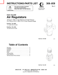
Back Pressure Valve
300 psi (21 bar, 2.1 MPa) Maximum Inbound Pressure
180 psi (12.4 bar, 1.24 MPa) Maximum Regulated Pressure
Model 205–122, Series C
Equipment misuse can cause the equipment to rupture or malfunction and result in serious injury.
This equipment is for professional use only.
Read all instruction manuals, tags, and labels before operating the equipment.
Use the equipment only for its intended purpose. If you are uncertain about usage, call your Graco
distributor.
Do not alter or modify this equipment. Use only genuine Graco parts and accessories.
Check equipment daily. Repair or replace worn or damaged parts immediately.
Do not exceed the maximum working pressure of the lowest rated component in your system. This
equipment has a 300 psi (21 bar, 2.1 MPa) maximum inbound pressure and a 180 psi (12.4 bar,
1.24 MPa) maximum regulated pressure.
Use fluids and solvents which are compatible with the equipment wetted parts. Refer to the Technical Data section of all equipment manuals. Read the fluid and solvent manufacturer’s warnings.
Comply with all applicable local, state, and national fire, electrical, and safety regulations.
PRESSURIZED EQUIPMENT HAZARD
Spray from the gun, hose leaks, or ruptured components can splash fluid in the eyes or on the skin
and cause serious injury.
Do not stop or deflect leaks with your hand, body, glove or rag.
Tighten all fluid connections before operating the equipment.
Follow the Pressure Relief Procedure on page 2 whenever you: are instructed to relieve pressure; stop spraying; clean, check, or service the equipment; and install or clean the spray nozzle.
GRACO INC.
P.O. BOX 1441 MINNEAPOLIS, MN
COPYRIGHT 1994, GRACO INC.
Graco Inc. is registered to I.S. EN ISO 9001
55440–1441
Pressure Relief Procedure.
WARNING
PRESSURIZED EQUIPMENT HAZARD
The system pressure must be manually relieved to
prevent the system from starting or spraying accidentally.
To reduce the risk of an injury from accidental spray from
the gun, splashing fluid, or moving parts, follow the
Pressure Relief Procedure whenever you:
11
22
are instructed to relieve the pressure,
stop spraying,
check or service any of the system equipment,
or install or clean the spray nozzle.
Fig. 2
1.
Shut off the power to the pump. If you are using an air–
powered pump, open the bleed–type master air valve.
2.
Trigger the gun.
3.
Relieve the line pressure by turning the adjusting screw
(26) counterclockwise until there is no spring pressure.
Installation
This valve is used in a circulating system to regulate the back
pressure to spray guns and to maintain the proper circulating
pressure throughout the system.
The valve is adjustable to control fluid pressure in a circulating system from 0 to 180 psi (0 to 12.4 bar, 0 to 1.24 MPa).
CAUTION
To prevent damage to the diaphragm, the hard carbide seat
and stem, and other sensitive parts, handle the valve carefully.
Install the valve in the return line of the spray guns, downstream from the last gun. See Fig. 1. Connect the return line
to the 3/8 npsm(m) inlet (22) and the 3/8 npsm(f) outlet (11).
Be sure the connections match the direction of fluid flow in
the line. See Fig. 2.
C
Operation
The back–pressure valve controls pressure in the fluid
return–line. Adjust the pump pressure and the back–pressure
valve for the best combination of spraying pressure and fluid
circulation.
To adjust the back–pressure valve, loosen the locknut (27)
and insert the hex key wrench (7) into the socket on the
adjusting screw (26). Turn the screw clockwise to increase
pressure in the return line. Turn the screw counterclockwise
to decrease pressure in the return line. Lock in the adjustment by tightening the locknut (27).
NOTE: Always check and adjust the back pressure valve if
you make changes to the system such as a change of fluids,
the length of the lines, and the number of spray guns.
Flush the valve with a compatible solvent whenever the rest
of the system is being flushed. Fully open the valve before
flushing by turning the adjustment screw counterclockwise.
Always use the lowest possible pressure when flushing.
Service
NOTE: Clean and check the valve regularly to maintain it in
good working condition. Refer to the Parts drawing on page
3.
1.
Remove the valve from the system.
2.
Disassemble the pressure gauge (5) and the tube (16)
from the inlet adapter (22). Remove the inlet adapter and
the outlet union (11) from the housing (25).
3.
Unscrew the cap (28) from the housing (25). Remove the
adjusting screw (26) and the locknut (27).
4.
Remove the spring plate (15) and the spring (13).
5.
Loosen the cap nut (4). Disassemble the diaphragm and
its related parts (2,10, 18, 19, 20, 21).
B
A
D
E
04520
F
CAUTION
Fig. 1
04521
Be careful not to damage the valve seat (1) or stem (2)
which are made of hard carbide.
Service
6.
Remove the valve seat (1) and the gasket (9) from the
housing (25).
7.
Clean all the parts with a compatible solvent. Check the
parts for wear or damage. Replace worn or damaged
parts.
8.
Assemble the valve seat (1) and the gasket (9) into the
housing (25). Torque to 70–80 in–lb (8–9 N.m).
9.
Assemble the diaphragm and the related parts as shown
in the parts drawing. Torque the cap nut (4) to 27–33
in–lb (3.1–3.7).
10. Install the spring (13) and the spring plate (15).
11. Screw the cap (28) onto the housing (25). Torque to
115–125 in–lb (13–14 N.m). Reinstall the locknut (27)
and the adjusting screw (26) into the cap (28).
12. Assemble the inlet adapter (22) and the outlet union (11)
into the housing.
13. Assemble the gauge (5) to the pressure tube (16). Use a
thread sealant to ensure a good seal. Install the tube and
the gauge into the inlet adapter (22).
14. Install the valve in the system.
Parts
7
Torque to
115–125 in–lb
(13–14 N.m)
Torque to
27–33 in–lb
(3.1–3.7 N.m)
Torque to
70–80 in–lb
(8–9 N.m)
26
27
Ref.
No.
Part No.
Description
1
2
4
5
236–893
236–894
100–529
187–876
7
9
10
11
101–976
189–817
154–789
155–665
13
15
16
18
19
20
21
22
157–796
160–180
160–745
189–816
177–430
177–432
177–431
162–265
25
26
162–811
112–844
27
28
100–111
189–815
SEAT, valve
STEM, valve
NUT, hex, cap, 5/16–18
PRESSURE GAUGE, 0–300 psi
(0–21 bar, 0–2.1 MPa) pressure range
WRENCH, hex key, 3/8”
GASKET, copper
GASKET, copper
UNION, 3/8 npt(m) x
3/8 npsm(f) swivel
SPRING, compression
PLATE, spring
TUBE, fluid gauge
PLATE, backup
GASKET, valve
DIAPHRAGM PLATE, support
DIAPHRAGM
INLET ADAPTER, 3/8–18 npsm(m),
3/8–18 npt(m), 1/4–18 npt(f)
VALVE HOUSING
ADJUSTING SCREW, 1/2–20 x
1–5/8 inch long
LOCKNUT, 1/2–20
REGULATOR CAP
28
15
13
4
10
18
20
21
5
16
22
19
2
1 9
11
25
Qty.
1
1
1
1
1
1
1
1
1
1
1
1
1
1
1
1
1
1
1
1
Keep these spare parts on hand to reduce down time.
04519
Graco Phone
Number
TO PLACE AN ORDER, contact your Graco distributor, or
call this number to identify the distributor closest to you:
1–800–367–4023 Toll Free
Manual Change
Summary
Assembly
Changed
Part
Status
Ref
No.
Part No.
Name
205–122
Series to C
Old
New
Old
New
1
1
5
5
212–030
236–893
101–180
187–876
Seat
Seat
Gauge
Gauge
Maximum inbound fluid pressure is increased to 300 psi (21
bar, 2.1 MPa).
Technical Data
Dimensions
Maximum inbound fluid pressure . 300 psi (21 bar, 2.1 MPa)
Regulated pressure range 0–180 psi (0–12.4 bar, 1.24 MPa)
Valve orifice diameter . . . . . . . . . . . . . . . 0.156 inch (3.96 mm)
Approximate maximum
flow capacity . . . . . . . . . . . . . . . . . . . . . . 2 gpm (7.6 liter/min)
Wetted parts . . . . . . . . . . . . . . 303 stainless steel, plated steel
brass, tungsten carbide, buna–N impregnated
nylon, PTFE,elastomer treated cellulose fiber
Height (A) . . . . . . . . . . . . . . . . . . . . . . . . . . . . . 7 inch (178 mm)
Width (C) . . . . . . . . . . . . . . . . . . . . . . . . . . . . . . 5 inch (127 mm)
Fluid inlet (B) . . . . . . . . . . . . . . . . . . . . . . . . . . . . . 3/8 npsm(m)
Fluid outlet (D) . . . . . . . . . . . . . . . . . . . . . . . . . . . . . 3/8 npsm(f)
Diameter (E) . . . . . . . . . . . . . . . . . . . . . . . 2.44 inch (51.28 mm)
A
E
D
B
C
04520
The Graco Warranty and Disclaimers
Graco warrants all equipment listed in this manual which is manufactured by Graco and bearing its name to be free from defects in
material and workmanship on the date of sale by an authorized Graco distributor to the original purchaser for use. With the exception of
any special extended or limited warranty published by Graco, Graco will, for a period of twelve months from the date of sale, repair or
replace any part of the equipment determined by Graco to be defective. This warranty applies only when the equipment is installed,
operated and maintained in accordance with Graco’s written recommendations.
This warranty does not cover, and Graco shall not be liable for general wear and tear, or any malfunction, damage or wear caused by
faulty installation, misapplication, abrasion, corrosion, inadequate or improper maintenance, negligence, accident, tampering, or
substitution of non-Graco component parts. Nor shall Graco be liable for malfunction, damage or wear caused by the incompatibility of
Graco equipment with structures, accessories, equipment or materials not supplied by Graco, or the improper design, manufacture,
installation, operation or maintenance or structures, accessories, equipment or materials not supplied by Graco.
This warranty is conditioned upon the prepaid return of the equipment claimed to be defective to an authorized Graco distributor for
verification of the claimed defect. If the claimed defect is verified, Graco will repair or replace free of charge any defective parts. The
equipment will be returned to the original purchaser transportation prepaid. If inspection of the equipment does not disclose any defect
in material or workmanship, repairs will be made at a reasonable charge, which charges may include the costs of parts, labor, and
transportation.
Graco’s sole obligation and buyer’s sole remedy for any breach of warranty shall be as set forth above. The buyer agrees that no other
remedy (including, but not limited to, incidental or consequential damages for lost profits, lost sales, injury to person or property, or any
other incidental or consequential loss) shall be available. Any action for breach of warranty must be brought within two (2) years of the
date of sale.
GRACO MAKES NO WARRANTY, AND DISCLAIMS ALL IMPLIED WARRANTIES OF MERCHANTABILITY AND FITNESS FOR
A PARTICULAR PURPOSE IN CONNECTION WITH ACCESSORIES, EQUIPMENT, MATERIALS OR COMPONENTS SOLD BUT
NOT MANUFACTURED BY GRACO. These items sold, but not manufactured by Graco (such as electric motors, gas engines,
switches, hose, etc.), are subject to the warranty, if any, of their manufacturer. Graco will provide purchaser with reasonable assistance
in making any claim for breach of these warranties.
In no event will Graco be liable for indirect, incidental, special or consequential damages resulting from Graco supplying equipment
hereunder, or the furnishing, performance, or use of any products or other goods sold hereto, whether due to a breach of contract,
breach of warranty, the negligence of Graco, or otherwise.
FOR GRACO CANADA CUSTOMERS
The parties acknowledge that they have required that the present document, as well as all documents, notices and legal proceedings
entered into, given or instituted pursuant hereto or relating directly or indirectly hereto, be drawn up in English. Les parties
reconnaissent avoir convenu que la rédaction du présente document sera en Anglais, ainsi que tous documents, avis et procédures
judiciaires exécutés, donnés ou intentés à la suite de ou en rapport, directement ou indirectement, avec les procédures concernées.
All written and visual data contained in this document reflects the latest product information available at the time of publication.
Graco reserves the right to make changes at any time without notice.
Sales Offices: Minneapolis, Detroit, Los Angeles
Foreign Offices: Belgium, Canada, England, Korea, France, Germany, Hong Kong, Japan
GRACO INC.
P.O. BOX 1441 MINNEAPOLIS, MN
55440–1441
PRINTED IN U.S.A. 306–640 October, 1958; Revised June, 1997